

Page 1
IUT-10 / IUT-11
Operating instructions
Betriebsanleitung
Universal transmitter for applications in hazardous environments
GB
GB
GBF
DUniversaltransmitter für den Einsatz in explosionsgefährdeten Bereichen
WIKA Alexander Wiegand GmbH & Co. KG
Alexander-Wiegand-Straße 30
63911 Klingenberg/ Germany
Tel. (+49) 93 72/132-295
Fax (+49) 93 72/132-706
E-Mail support-tronic@wika.de
www.wika.de
IUT-10
IUT-11
Page 2

Universal IS Pressure Transmitter UniTrans
Contents
Contents
1 General Safety Instructions . . . . . . . . . . . . . . . . . . . . . . . . . . . . . . . . .79
2 Special Intrinsic Safety Instructions . . . . . . . . . . . . . . . . . . . . . . . . . .80
2.1 Protection of diaphragm . . . . . . . . . . . . . . . . . . . . . . . . . . . . . . . . . . . . . . . . . . . . 80
2.2 Special wiring advice . . . . . . . . . . . . . . . . . . . . . . . . . . . . . . . . . . . . . . . . . . . . . . . 80
2.3 Connection to Zone 0 . . . . . . . . . . . . . . . . . . . . . . . . . . . . . . . . . . . . . . . . . . . . . . 80
2.4 Special precaution for connection to Zone 0 and or Zone 20 . . . . . . . . . . . . . . . . 80
2.5 Instructions for temperature ranges . . . . . . . . . . . . . . . . . . . . . . . . . . . . . . . . . . . 81
2.6 Special instructions for dust explosion protection . . . . . . . . . . . . . . . . . . . . . . . . . 81
3 EC-Declaration of Conformity. . . . . . . . . . . . . . . . . . . . . . . . . . . . . . . .82
4 EC-Type Examination Certificate . . . . . . . . . . . . . . . . . . . . . . . . . . . .83
5 Product Description. . . . . . . . . . . . . . . . . . . . . . . . . . . . . . . . . . . . . . . .97
5.1 Construction . . . . . . . . . . . . . . . . . . . . . . . . . . . . . . . . . . . . . . . . . . . . . . . . . . . . . 97
5.1.1 Pressure Transducer . . . . . . . . . . . . . . . . . . . . . . . . . . . . . . . . . . . . . . . . . . . . . . . 97
5.1.2 Processing Unit . . . . . . . . . . . . . . . . . . . . . . . . . . . . . . . . . . . . . . . . . . . . . . . . . . . 98
5.1.3 Display Unit . . . . . . . . . . . . . . . . . . . . . . . . . . . . . . . . . . . . . . . . . . . . . . . . . . . . . . 98
5.2 Function. . . . . . . . . . . . . . . . . . . . . . . . . . . . . . . . . . . . . . . . . . . . . . . . . . . . . . . . . 99
5.2.1 Functions of Transmitters without Displays. . . . . . . . . . . . . . . . . . . . . . . . . . . . . . 99
5.2.2 Functions of Transmitters with Displays . . . . . . . . . . . . . . . . . . . . . . . . . . . . . . . . 99
5.2.3 Functional features of transmitters with HART-Communication . . . . . . . . . . . . . 100
5.3 Installation Examples . . . . . . . . . . . . . . . . . . . . . . . . . . . . . . . . . . . . . . . . . . . . . 101
6 Technical Data . . . . . . . . . . . . . . . . . . . . . . . . . . . . . . . . . . . . . . . . . . . 103
6.1 Input-values. . . . . . . . . . . . . . . . . . . . . . . . . . . . . . . . . . . . . . . . . . . . . . . . . . . . . 103
6.2 Output-values . . . . . . . . . . . . . . . . . . . . . . . . . . . . . . . . . . . . . . . . . . . . . . . . . . . 103
6.3 Construction . . . . . . . . . . . . . . . . . . . . . . . . . . . . . . . . . . . . . . . . . . . . . . . . . . . . 104
6.4 Auxilliary Power . . . . . . . . . . . . . . . . . . . . . . . . . . . . . . . . . . . . . . . . . . . . . . . . . . 105
6.5 Ambient Conditions . . . . . . . . . . . . . . . . . . . . . . . . . . . . . . . . . . . . . . . . . . . . . . . 105
6.6 Process Conditions . . . . . . . . . . . . . . . . . . . . . . . . . . . . . . . . . . . . . . . . . . . . . . . 106
6.7 Safety-related nominal values for IS protection conditions . . . . . . . . . . . . . . . . . 106
6.8 Product labels (example). . . . . . . . . . . . . . . . . . . . . . . . . . . . . . . . . . . . . . . . . . . 107
7 Installation . . . . . . . . . . . . . . . . . . . . . . . . . . . . . . . . . . . . . . . . . . . . . .108
7.1 Pressure Transmitter Installation. . . . . . . . . . . . . . . . . . . . . . . . . . . . . . . . . . . . . 108
7.2 Display Unit Upgrades. . . . . . . . . . . . . . . . . . . . . . . . . . . . . . . . . . . . . . . . . . . . . 108
7.3 Housing Reconfiguration . . . . . . . . . . . . . . . . . . . . . . . . . . . . . . . . . . . . . . . . . . . 109
7.4 Electrical Connection. . . . . . . . . . . . . . . . . . . . . . . . . . . . . . . . . . . . . . . . . . . . . . 110
7.5 Pressure Compensation when using a Relative Pressure Sensor . . . . . . . . . . . 111
8 Operation of Devices without Displays . . . . . . . . . . . . . . . . . . . . . . .112
8.1 Preparation . . . . . . . . . . . . . . . . . . . . . . . . . . . . . . . . . . . . . . . . . . . . . . . . . . . . . 112
8.2 Key Functions (only for transmitters without display) . . . . . . . . . . . . . . . . . . . . . 112
2266939.05 D/GB 06/2006
8.3 Calibration with Pressure . . . . . . . . . . . . . . . . . . . . . . . . . . . . . . . . . . . . . . . . . . 113
Subject to c hange due to techni cal modifications . © Copyright W IKA Alexander Wieg and GmbH & Co. KG / Germany
WIKA Alexand er Wiegand GmbH & Co. KG · Alexa nder-Wiegand-Str . · 63911 Klingen berg · (09372) 1 32 - 710 · Fax - 7 06 · E-mail: sup port-tronic@wik a.de · www.wika. de
77
Page 3

Universal IS Pressure Transmitter UniTrans
Contents
8.3.1 Zero Point Calibration. . . . . . . . . . . . . . . . . . . . . . . . . . . . . . . . . . . . . . . . . . . . . . 113
8.3.2 Span Calibration . . . . . . . . . . . . . . . . . . . . . . . . . . . . . . . . . . . . . . . . . . . . . . . . . . 113
8.4 Calibration without Pressure. . . . . . . . . . . . . . . . . . . . . . . . . . . . . . . . . . . . . . . . .114
8.4.1 Zero Point Calibration. . . . . . . . . . . . . . . . . . . . . . . . . . . . . . . . . . . . . . . . . . . . . . 114
8.4.2 Span Calibration . . . . . . . . . . . . . . . . . . . . . . . . . . . . . . . . . . . . . . . . . . . . . . . . . . 114
8.4.3 Mounting correction of the sensor . . . . . . . . . . . . . . . . . . . . . . . . . . . . . . . . . . . . 116
8.5 Integration Time (Damping) Adjustment. . . . . . . . . . . . . . . . . . . . . . . . . . . . . . . . 116
8.6 Reset to Default . . . . . . . . . . . . . . . . . . . . . . . . . . . . . . . . . . . . . . . . . . . . . . . . . . 117
9 Operation of Transmitters with Display. . . . . . . . . . . . . . . . . . . . . . . 118
9.1 The Display. . . . . . . . . . . . . . . . . . . . . . . . . . . . . . . . . . . . . . . . . . . . . . . . . . . . . . 118
9.2 Key Functions. . . . . . . . . . . . . . . . . . . . . . . . . . . . . . . . . . . . . . . . . . . . . . . . . . . . 119
9.3 The Programming Mode. . . . . . . . . . . . . . . . . . . . . . . . . . . . . . . . . . . . . . . . . . . .119
9.4 Default Data (factory settings) . . . . . . . . . . . . . . . . . . . . . . . . . . . . . . . . . . . . . . . 120
9.5 Main Menu . . . . . . . . . . . . . . . . . . . . . . . . . . . . . . . . . . . . . . . . . . . . . . . . . . . . . . 121
9.5.1 Main Menu: Display . . . . . . . . . . . . . . . . . . . . . . . . . . . . . . . . . . . . . . . . . . . . . . . 122
9.5.2 Main Menu: Calibration of zero and span (with / without pressure) . . . . . . . . . . . 124
9.5.3 Main Menu: Output . . . . . . . . . . . . . . . . . . . . . . . . . . . . . . . . . . . . . . . . . . . . . . . . 125
9.5.4 Main Menu: Evaluation . . . . . . . . . . . . . . . . . . . . . . . . . . . . . . . . . . . . . . . . . . . . .126
9.5.5 Main Menu: Language . . . . . . . . . . . . . . . . . . . . . . . . . . . . . . . . . . . . . . . . . . . . . 128
9.5.6 Main Menu: Service . . . . . . . . . . . . . . . . . . . . . . . . . . . . . . . . . . . . . . . . . . . . . . . 129
10 Transmitter Operation with HART®-functionality . . . . . . . . . . . . . . 130
10.1 Possible HART® connections . . . . . . . . . . . . . . . . . . . . . . . . . . . . . . . . . . . . . . .130
10.1.1 Connection of the HART®- hand terminal . . . . . . . . . . . . . . . . . . . . . . . . . . . . . . 130
10.1.2 Connecting the HART®-modem for PC operation . . . . . . . . . . . . . . . . . . . . . . . . 131
10.2 Operation via PC and the software PACTware‘ . . . . . . . . . . . . . . . . . . . . . . . . . . 132
10.2.1 Menu 'Device info'. . . . . . . . . . . . . . . . . . . . . . . . . . . . . . . . . . . . . . . . . . . . . . . . . 133
10.2.2 Menu 'Description' . . . . . . . . . . . . . . . . . . . . . . . . . . . . . . . . . . . . . . . . . . . . . . . . 133
10.2.3 Submenu 'Parameter' - Device info . . . . . . . . . . . . . . . . . . . . . . . . . . . . . . . . . . . 134
10.2.4 Submenu 'Parameter' - Calibration. . . . . . . . . . . . . . . . . . . . . . . . . . . . . . . . . . . .136
10.2.5 Submenu 'Parameter' - Output . . . . . . . . . . . . . . . . . . . . . . . . . . . . . . . . . . . . . . . 138
10.2.6 Submenu 'Parameter' - Evaluation . . . . . . . . . . . . . . . . . . . . . . . . . . . . . . . . . . . . 139
10.2.7 Window 'Service'. . . . . . . . . . . . . . . . . . . . . . . . . . . . . . . . . . . . . . . . . . . . . . . . . . 141
10.2.8 Window 'Simulation' . . . . . . . . . . . . . . . . . . . . . . . . . . . . . . . . . . . . . . . . . . . . . . . 143
10.2.9 Window 'Measured value' . . . . . . . . . . . . . . . . . . . . . . . . . . . . . . . . . . . . . . . . . . .144
10.2.10 Window 'Trend' . . . . . . . . . . . . . . . . . . . . . . . . . . . . . . . . . . . . . . . . . . . . . . . . . . . 144
10.2.11 Window 'Burst mode' . . . . . . . . . . . . . . . . . . . . . . . . . . . . . . . . . . . . . . . . . . . . . . 145
10.2.12 Window 'Diagnosis'. . . . . . . . . . . . . . . . . . . . . . . . . . . . . . . . . . . . . . . . . . . . . . . . 145
11 Diagnostics and Service. . . . . . . . . . . . . . . . . . . . . . . . . . . . . . . . . . . 146
12 Disposal . . . . . . . . . . . . . . . . . . . . . . . . . . . . . . . . . . . . . . . . . . . . . . . . 146
13 Appendix . . . . . . . . . . . . . . . . . . . . . . . . . . . . . . . . . . . . . . . . . . . . . . . 147
13.1 Dimension Diagrams . . . . . . . . . . . . . . . . . . . . . . . . . . . . . . . . . . . . . . . . . . . . . . 147
13.2 Model Key. . . . . . . . . . . . . . . . . . . . . . . . . . . . . . . . . . . . . . . . . . . . . . . . . . . . . . . 151
13.3 Warranty Conditions . . . . . . . . . . . . . . . . . . . . . . . . . . . . . . . . . . . . . . . . . . . . . . . 153
13.4 Glossary . . . . . . . . . . . . . . . . . . . . . . . . . . . . . . . . . . . . . . . . . . . . . . . . . . . . . . . . 153
13.5 Units of Pressure Measurement . . . . . . . . . . . . . . . . . . . . . . . . . . . . . . . . . . . . . . 153
Subject to c hange due to techni cal modifications . © Copyright W IKA Alexander Wieg and GmbH & Co. KG / Germany
WIKA Alexander Wiegand GmbH & Co. KG · Alexand er-Wiegand-Str. · 6391 1 Klingenberg · (09372) 132 - 710 · Fax - 706 · E-mail: support-tronic@wika.de · www.wika.de
78
2266939.05 D/GB 06/2006
Page 4

Universal IS Pressure Transmitter UniTrans
g
1 General Safety Instructions
• Select the appropriate pressure transmitter with regard to scale range,
performance and specific measurement conditions prior to installing and
Warnin
starting the instrument.
• Observe the relevant national regulations (e.g.: EN 50178, NEC, CEC)
and observe the applicable standards and directives for special
applications (e.g. with dangerous media such as oxygen, acetylene,
flammable gases or liquids and toxic gases or liquids and with
refrigeration plants or compressors).
If you do not observe the appropriate regulations, serious injuries
and/or damage can occur!
• Open pressure connections only after the system is without
pressure!
• Please make sure that the pressure transmitter is only used within the
overload threshold limit at all times!
• Observe the ambient and working conditions outlined in chapter 6
"Technical Data"
• Ensure that the pressure transmitter is only operated in accordance with
the provisions, i.e. as described in the following instructions.
• Do not interfere with or change the pressure transmitter in any other way
than described in these operating instructions...
• Remove the pressure transmitter from service and mark it to prevent it
from being used again accidentally, if it becomes damaged or unsafe for
operation..
• Take precautions with regard to remaining media in removed
pressure transmitter. Remaining media in the prsesure port may
be hazardous or toxic!
• Have repairs performed by the manufacturer only.
• Consider the details given in the EC-type examination certificate as well
as the respective specifications for explosion hazard use of the country
concerned (e.g.: IEC 60079, NEC, CEC). If you do not observe these
stipulations, serious injuries and/or damage can occur.
Other important safety guidelines can be found in the different sections of
this instruction manual.
Contents
2266939.05 D/GB 06/2006
Subject to c hange due to techni cal modifications . © Copyright W IKA Alexander Wieg and GmbH & Co. KG / Germany
WIKA Alexand er Wiegand GmbH & Co. KG · Alexa nder-Wiegand-Str . · 63911 Klingen berg · (09372) 1 32 - 710 · Fax - 7 06 · E-mail: sup port-tronic@wik a.de · www.wika. de
79
Page 5
Universal IS Pressure Transmitter UniTrans
Special Intrinsic Safety Instructions
2 Special Intrinsic Safety Instructions
2.1 Protection of diaphragm
As soon as the diaphragm of an instrument gets damaged, absolutely no intrinsic
safety can be guaranteed any longer! Thus the diaphragm must not come in contact with abrasive substances! The diaphragm must be protected against pressure
Warning
peaks and must not be touched by tools! Information about material consistency
against corrosion and diffusion can be found in our WIKA Handbook, 'Pressure and
Temperature Measurement' (German: ISBN 3-9804074-0-3, English: ISBN 39804074-1-1).
2.2 Special wiring advice
The housing must always be connected to earth to protect the instrument against
electromagnetic fields and electrostatic charges.
Warning
The cables and wires must not be damaged.
Cables for applications in Zone 1 and 2 or Zone 21 and 22 must be checked with
a test voltage between conductor/earth, conductor/screen, screen/earth of more
than 500 V (AC).
Flying leads with fine wires must be covered by an end splice (cable preparation).
Both the internal capacity and inductivity must be considered.
Conductive screens may only be connected to earth one-sided and outside the
hazardous area.
2.3 Connection to Zone 0
(In general Zone 0 is given when the instrument is surrounded by a mixture of
explosive gases more than 1.000 hours per year = continuous hazard. The trans-
Warning
mitter may only be operated under Zone 0 conditions, as long as an atmospherical
pressure of 0.8 to 1.1 bar is guaranteed).
The circuits must be of type Ex ia.
The ingress protection must comply to IP 67 according to IEC 529.
2.4 Special precaution for connection to Zone 0 and or Zone 20
Make absolutely sure to follow the advice given in the IEC publication 60 529 for
connection to Zone 0 and/or Zone 20 for IP 67 pressure connections!
Warning
Warning
Installation in non-metallic vessels:
All metallic parts reaching into Zone 0 and/or Zone 20 must be grounded.
The intrinsically safe circuit must be decoupled from the regular circuit.
If the mounting position is less than 1m away from the transition into Zone 0 and/or
Zone 20 an overvoltage protection must be integrated. This can either be done
within the transmitter (option: overvoltage protection), or outside the transmitter by
the customer himself.
Subject to c hange due to techni cal modifications . © Copyright W IKA Alexander Wieg and GmbH & Co. KG / Germany
WIKA Alexander Wiegand GmbH & Co. KG · Alexander- Wiegand-Str. · 6 3911 Klingenberg · (09372) 132 - 710 · Fax - 706 · E-mail: sup port-tronic@wika.d e ·
80
www.wika.de
2266939.05 D/GB 06/2006
Page 6
Universal IS Pressure Transmitter UniTrans
Special Intrinsic Safety Instructions
2.5 Instructions for temperature ranges
Observe the permissible surface temperatures applicable for this range according
to the defined temperature classes.
Warning
Warning
Observe the maximum temperature value (of the temperature range defined under
item 15.3. in the EC type test certificate at the hexagon of the process connection.
Protect the pressure transmitter against touching or affix a warning notice.
Insulate heat sources thermally from the pressure transmitter (e.g. pipes or tanks).
2.6 Special instructions for dust explosion protection
Ensure that under hazardous dust environments the pressure transmitter is mounted in a shielded section and protect it against shocks.
Warning
Warning
When installing the pressure transmitter or the cable gland into areas which require
category 1D equipment, ensure that ingress protection IP 6X according to IEC 60
529 is guaranteed.
Observe the EN 50281-1-2 in relation to e.g. dust deposits and temperature.
The permissible ambient temperatures as well as the maximum surface temperatures are to be taken from the EC type test certificate.
4
2266939.05 D/GB 06/2006
Subject to c hange due to techni cal modifications . © Copyright W IKA Alexander Wieg and GmbH & Co. KG / Germany
WIKA Alexander Wiegand GmbH & Co. KG · Alexander- Wiegand-Str. · 6 3911 Klingenberg · (09372) 132 - 710 · Fax - 706 · E-ma il: support-tronic@wik a.de ·
www.wika.de
81
Page 7
Universal IS Pressure Transmitter UniTrans
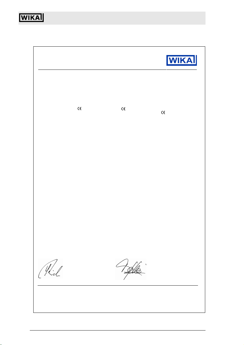
3 EC-Declaration of Conformity
EC-Declaration of Conformity
EG-Konformitäts-
erklärung
EC Declaration of
Conformity
Déclaration de
Conformité CE
Dokument Nr.: Document No.: Document No.:
11135212.01 11135212.01 11135212.01
Wir erklären in alleiniger
Verantwortung, dass die mit
gekennzeichneten Produkte
We declare under our sole
responsibility that the
marked products
Nous déclarons sous notre seule
responsabilité que les appareils
marqués
Typen: Models: Types:
IUT-10 / IUT-11 IUT-10 / IUT -11 IUT-10 / IUT-11
Beschreibung: Description: Description:
Universaltransmitter
UniTrans
Universal Pressure Transmitter
UniTrans
Transmetteur de pression
UniTrans
gemäß gültigem Datenblatt: according to the valid data-sheet: selon fiche technique valide:
PE 86.02 PE 86.02 PE 86.02
die grundlegenden Anforderungen
der folgenden Richtlinie(n)
erfüllen:
97/23/EG (DGRL)
89/336/EWG (EMV),
94/9/EG (ATEX)
Die Geräte wurden entsprechend
den folgenden Normen geprüft:
EN 61326:1997 +A1 +A2 +A3 EN 61326:1997 +A1 +A2 +A3 EN 61326:1997 +A1 +A2 +A3
EN 50014:1997 +A1 +A2 EN 50014:1997 +A1 +A2 EN 50014:1997 +A1 +A2
EN 50020:2002 EN 50020:2002 EN 50020:2002
EN 50281-1-1:1998 +A1 EN 50281-1-1:1998 +A1 EN 50281-1-1:1998 +A1
EN 20284:1999 EN 20284:1999 EN 20284:1999
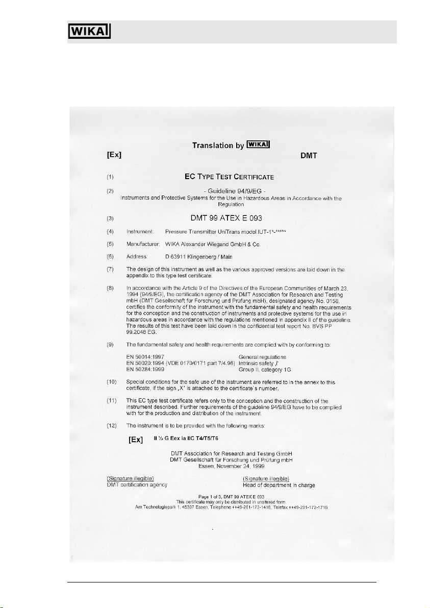
(1)
PS > 200 bar:
Bewertungsverfahren Modul A
(2)
EG-Baumusterprüfbescheinigung
DMT 99 ATEX E 093 von EXAM BBG
Prüf- und Zertifizier GmbH, Bochum
(Reg.-Nr. 0158).
WIKA Alexander Wiegand GmbH & Co. KG
Klingenberg, 2006-05-08
Geschäftsbereich TRONIC
Company division TRONIC
Ressort TRONIC
(1)
,
(2)
are in conformity with the essential
requirements of the directive(s)
97/23/EC (PED)
89/336/EEC (EMC),
94/9/EC (ATEX)
The devices have been tested
according to the standards:
(1)
PS > 200 bar:
assessment procedure Module A
(2)
EC-type-examination certificate
DMT 99 ATEX E 093 of EXAM BBG
Prüf- und Zertifizier GmbH, Bochum
(reg. no. 0158).
(1)
,
(2)
Qualitätsmanagement TRONIC
Quality management TRONIC
Management de la qualité TRONIC
sont conformes aux exigences
essentielles de la (les) directive(s)
97/23/CE (DESP)
89/336/CEE (CEM),
94/9/CE (ATEX)
Les appareils ont été vérifiés
suivant les normes:
(1)
PS > 200 bar:
procédure d’évaluation Module A
(2)
Attestation d’examen CE de type
DMT 99 ATEX E 093 de EXAM BBG
Prüf- und Zertifizier GmbH, Bochum
(reg. no. 0158).
(1)
,
(2)
i. V. Stefan Richter
WIKA Alexander Wiegand Tel +49 · 93 72 · 132-0 Kommanditgesellschaft: Komplementärin: WIKA Alexander Wiegand Verwaltungs GmbH
GmbH & Co. KG Fax +49 · 93 72 · 132-406/414 Sitz Klingenberg Sitz Klingenberg
Alexander-Wiegand-Straße www.wika.de Amtsgericht Aschaffenburg Amtsgericht Aschaffenburg HRB 306
63911 Klingenberg · Germany info@wika.de HRA 1819 Geschäftsführer: Alexander Wiegand
Subject to c hange due to techni cal modifications . © Copyright W IKA Alexander Wieg and GmbH & Co. KG / Germany
WIKA Alexander Wiegand GmbH & Co. KG · Alexand er-Wiegand-Str. · 6391 1 Klingenberg · (09372) 132 - 710 · Fax - 706 · E-mail: support-tronic@wika.de · www.wika.de
82
i. A. Thomas Gerling
2266939.05 D/GB 06/2006
Page 8
Universal IS Pressure Transmitter UniTrans
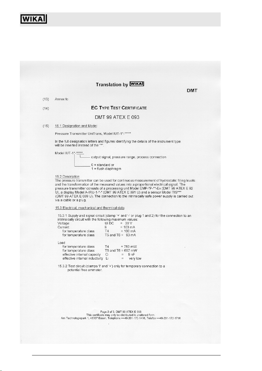
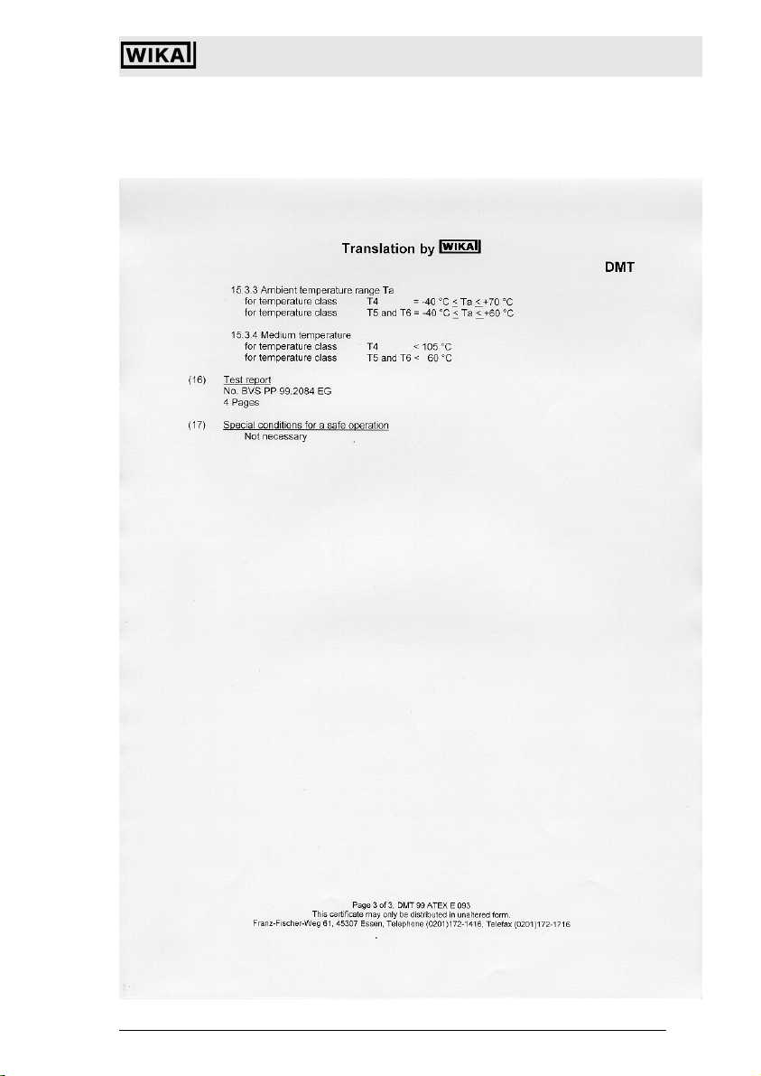
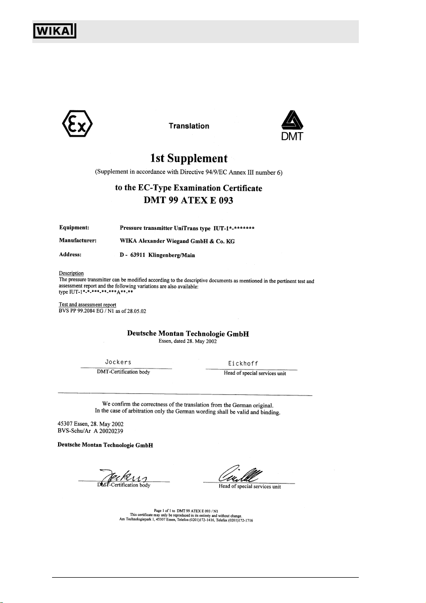
4 EC-Type Examination Certificate
EC-Type Examination Certificate
2266939.05 D/GB 06/2006
Subject to c hange due to techni cal modifications . © Copyright W IKA Alexander Wieg and GmbH & Co. KG / Germany
WIKA Alexand er Wiegand GmbH & Co. KG · Alexa nder-Wiegand-Str . · 63911 Klingen berg · (09372) 1 32 - 710 · Fax - 7 06 · E-mail: sup port-tronic@wik a.de · www.wika. de
83
Page 9
Universal IS Pressure Transmitter UniTrans
EC-Type Examination Certificate
Subject to c hange due to techni cal modifications . © Copyright W IKA Alexander Wieg and GmbH & Co. KG / Germany
WIKA Alexander Wiegand GmbH & Co. KG · Alexand er-Wiegand-Str. · 6391 1 Klingenberg · (09372) 132 - 710 · Fax - 706 · E-mail: support-tronic@wika.de · www.wika.de
84
2266939.05 D/GB 06/2006
Page 10
Universal IS Pressure Transmitter UniTrans
EC-Type Examination Certificate
2266939.05 D/GB 06/2006
Subject to c hange due to techni cal modifications . © Copyright W IKA Alexander Wieg and GmbH & Co. KG / Germany
WIKA Alexand er Wiegand GmbH & Co. KG · Alexa nder-Wiegand-Str . · 63911 Klingen berg · (09372) 1 32 - 710 · Fax - 7 06 · E-mail: sup port-tronic@wik a.de · www.wika. de
85
Page 11
Universal IS Pressure Transmitter UniTrans
EC-Type Examination Certificate
Subject to c hange due to techni cal modifications . © Copyright W IKA Alexander Wieg and GmbH & Co. KG / Germany
WIKA Alexander Wiegand GmbH & Co. KG · Alexand er-Wiegand-Str. · 6391 1 Klingenberg · (09372) 132 - 710 · Fax - 706 · E-mail: support-tronic@wika.de · www.wika.de
86
2266939.05 D/GB 06/2006
Page 12
Universal IS Pressure Transmitter UniTrans
EC-Type Examination Certificate
2266939.05 D/GB 06/2006
Subject to c hange due to techni cal modifications . © Copyright W IKA Alexander Wieg and GmbH & Co. KG / Germany
WIKA Alexand er Wiegand GmbH & Co. KG · Alexa nder-Wiegand-Str . · 63911 Klingen berg · (09372) 1 32 - 710 · Fax - 7 06 · E-mail: sup port-tronic@wik a.de · www.wika. de
87
Page 13
Universal IS Pressure Transmitter UniTrans
EC-Type Examination Certificate
Subject to c hange due to techni cal modifications . © Copyright W IKA Alexander Wieg and GmbH & Co. KG / Germany
WIKA Alexander Wiegand GmbH & Co. KG · Alexand er-Wiegand-Str. · 6391 1 Klingenberg · (09372) 132 - 710 · Fax - 706 · E-mail: support-tronic@wika.de · www.wika.de
88
2266939.05 D/GB 06/2006
Page 14
Universal IS Pressure Transmitter UniTrans
EC-Type Examination Certificate
2266939.05 D/GB 06/2006
Subject to c hange due to techni cal modifications . © Copyright W IKA Alexander Wieg and GmbH & Co. KG / Germany
WIKA Alexand er Wiegand GmbH & Co. KG · Alexa nder-Wiegand-Str . · 63911 Klingen berg · (09372) 1 32 - 710 · Fax - 7 06 · E-mail: sup port-tronic@wik a.de · www.wika. de
89
Page 15
Universal IS Pressure Transmitter UniTrans
EC-Type Examination Certificate
Subject to c hange due to techni cal modifications . © Copyright W IKA Alexander Wieg and GmbH & Co. KG / Germany
WIKA Alexander Wiegand GmbH & Co. KG · Alexand er-Wiegand-Str. · 6391 1 Klingenberg · (09372) 132 - 710 · Fax - 706 · E-mail: support-tronic@wika.de · www.wika.de
90
2266939.05 D/GB 06/2006
Page 16
Universal IS Pressure Transmitter UniTrans
EC-Type Examination Certificate
2266939.05 D/GB 06/2006
Subject to c hange due to techni cal modifications . © Copyright W IKA Alexander Wieg and GmbH & Co. KG / Germany
WIKA Alexand er Wiegand GmbH & Co. KG · Alexa nder-Wiegand-Str . · 63911 Klingen berg · (09372) 1 32 - 710 · Fax - 7 06 · E-mail: sup port-tronic@wik a.de · www.wika. de
91
Page 17
Universal IS Pressure Transmitter UniTrans
EC-Type Examination Certificate
Subject to c hange due to techni cal modifications . © Copyright W IKA Alexander Wieg and GmbH & Co. KG / Germany
WIKA Alexander Wiegand GmbH & Co. KG · Alexand er-Wiegand-Str. · 6391 1 Klingenberg · (09372) 132 - 710 · Fax - 706 · E-mail: support-tronic@wika.de · www.wika.de
92
2266939.05 D/GB 06/2006
Page 18
Universal IS Pressure Transmitter UniTrans
EC-Type Examination Certificate
2266939.05 D/GB 06/2006
Subject to c hange due to techni cal modifications . © Copyright W IKA Alexander Wieg and GmbH & Co. KG / Germany
WIKA Alexand er Wiegand GmbH & Co. KG · Alexa nder-Wiegand-Str . · 63911 Klingen berg · (09372) 1 32 - 710 · Fax - 7 06 · E-mail: sup port-tronic@wik a.de · www.wika. de
93
Page 19

Universal IS Pressure Transmitter UniTrans
EC-Type Examination Certificate
Translation by
g
DMT
st
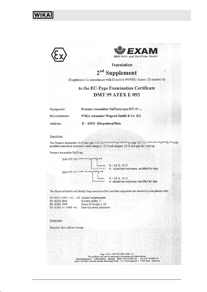
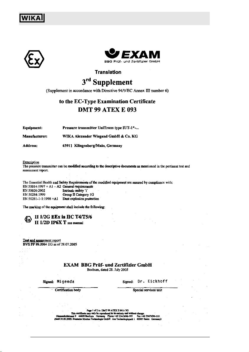
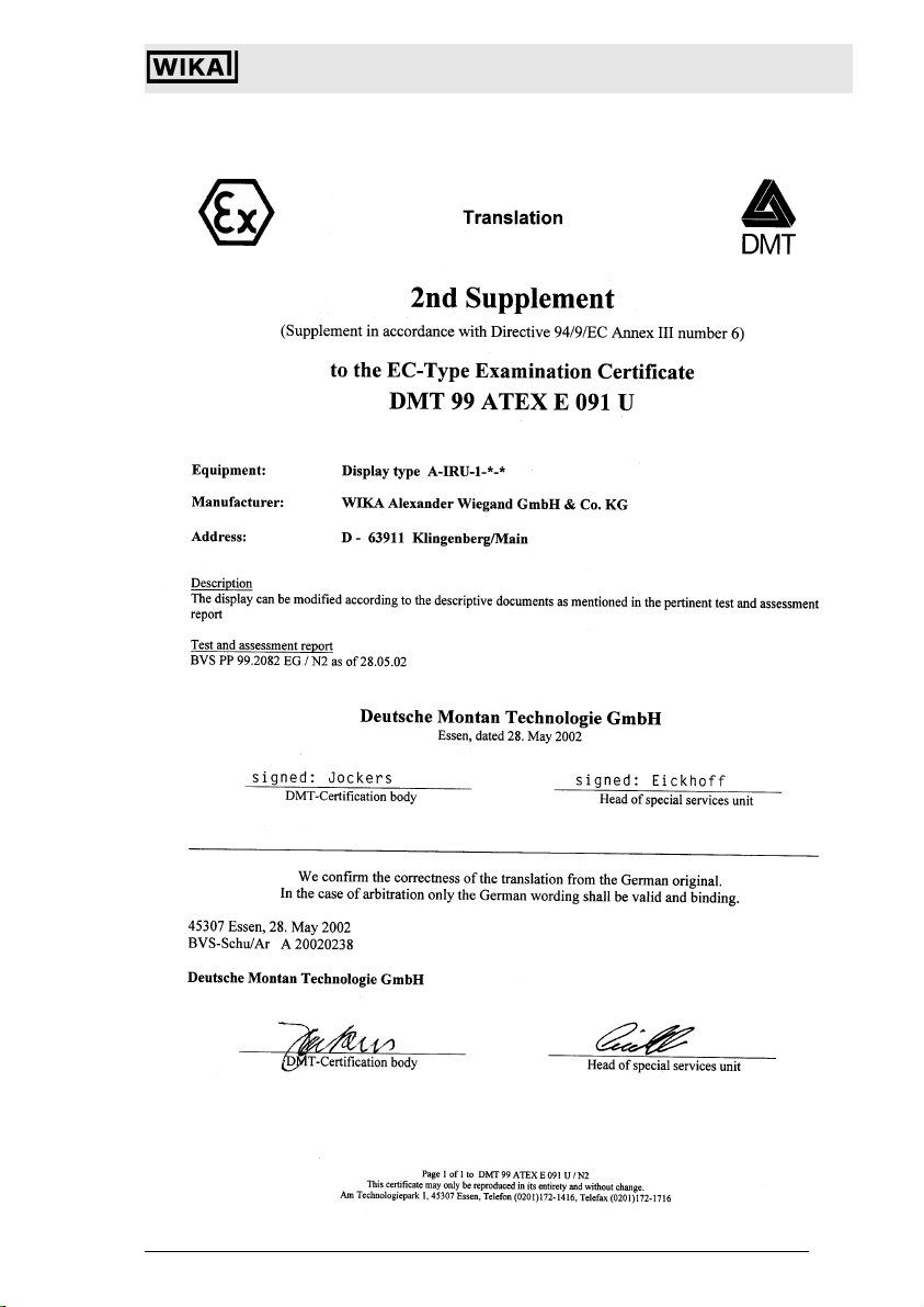
Addendum
(addition according to Guideline 94/9/EG, appendix III, number 6)
to the EC T
1
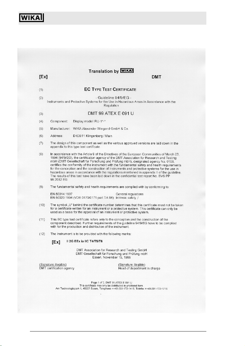
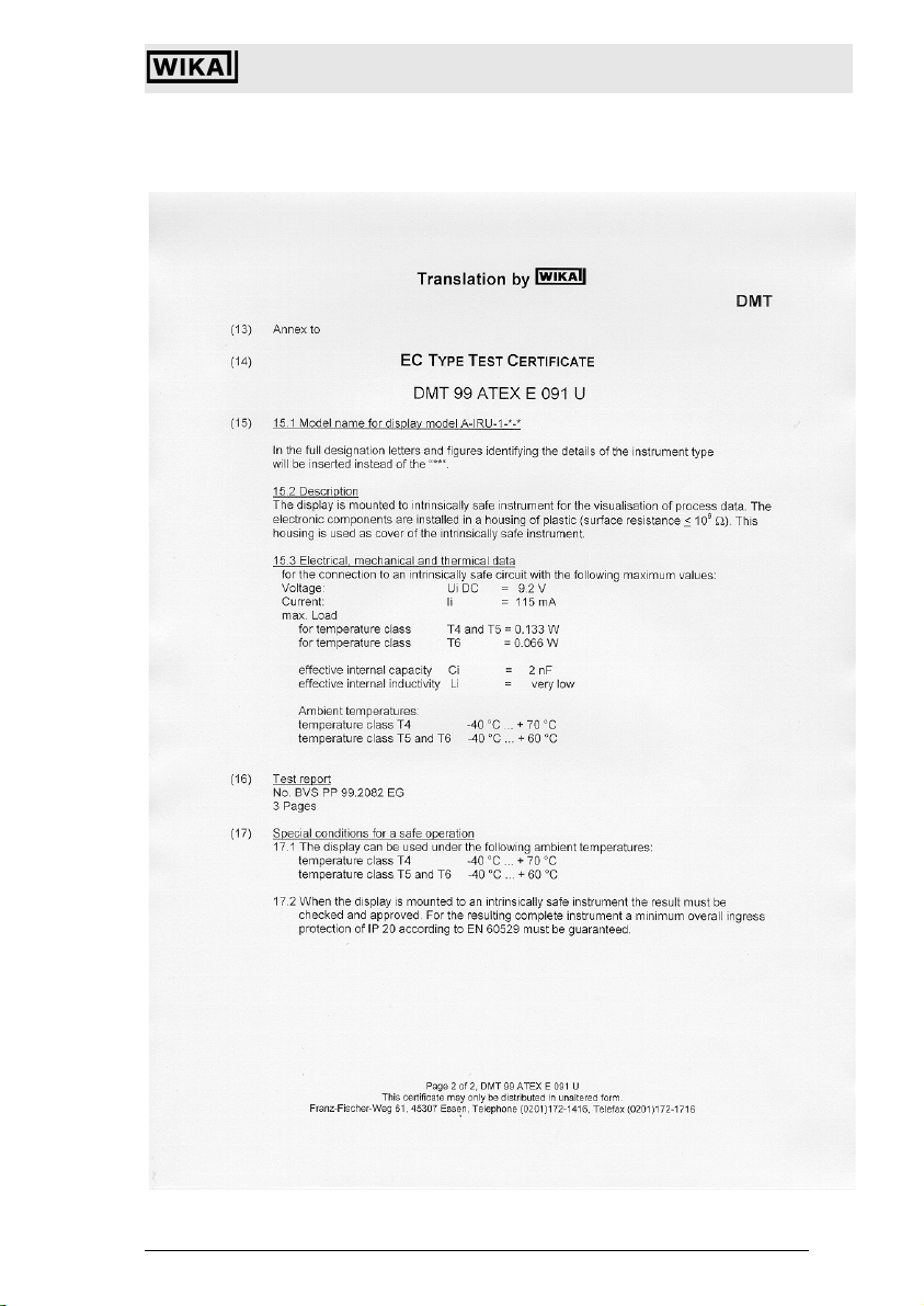
YPE TEST CERTIFICATE
DMT 99 ATEX E 091 U
Component: Display model IRU-1*-*
Manufacturer: WIKA Alexander Wiegand GmbH & Co.
Address: D 63911 Klingenberg / Main
Description
The display can also be manufactured in compliance with the test documents mentioned in the related
test certificate No. BVS PP 99.2082 EG / N1
Test report
No. BVS PP 99.2082 EG / N1, edition 04/28/2000, 3 Pages
DMT Deutsche Montan Technologie GmbH
DMT Association for Research and Testing GmbH
(Signature illegible) (Signature illegible)
DMT certification agency Head of department in charge
Essen, April 24, 2000
Page 1 of 1, of the addendum to the DMT 99 ATEX E 091 U
Am Technologiepark 1, 45307 Essen, Telephone (0201)172-1416, Telefa (0201)172-1716
Subject to c hange due to techni cal modifications . © Copyright W IKA Alexander Wieg and GmbH & Co. KG / Germany
WIKA Alexander Wiegand GmbH & Co. KG · Alexand er-Wiegand-Str. · 6391 1 Klingenberg · (09372) 132 - 710 · Fax - 706 · E-mail: support-tronic@wika.de · www.wika.de
94
This certificate may only be distributed in unaltered form.
2266939.05 D/GB 06/2006
Page 20
Universal IS Pressure Transmitter UniTrans
EC-Type Examination Certificate
2266939.05 D/GB 06/2006
Subject to c hange due to techni cal modifications . © Copyright W IKA Alexander Wieg and GmbH & Co. KG / Germany
WIKA Alexand er Wiegand GmbH & Co. KG · Alexa nder-Wiegand-Str . · 63911 Klingen berg · (09372) 1 32 - 710 · Fax - 7 06 · E-mail: sup port-tronic@wik a.de · www.wika. de
95
Page 21
Universal IS Pressure Transmitter UniTrans
EC-Type Examination Certificate
Subject to c hange due to techni cal modifications . © Copyright W IKA Alexander Wieg and GmbH & Co. KG / Germany
WIKA Alexander Wiegand GmbH & Co. KG · Alexand er-Wiegand-Str. · 6391 1 Klingenberg · (09372) 132 - 710 · Fax - 706 · E-mail: support-tronic@wika.de · www.wika.de
96
2266939.05 D/GB 06/2006
Page 22
Universal IS Pressure Transmitter UniTrans
Product Description
5 Product Description
The intrinsically safe pressure transmitter UniTrans can be used in level control
applications as well as for pressure measurement applications in process industry.
A variety of process connections, measurement ranges, main boards and display
options result in a product for a wide range of applications.
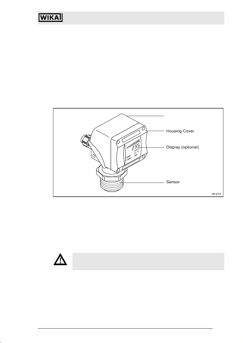
5.1 Construction
The UniTrans consists of a pressure sensor, a control interface unit and a housing
cover with optional display. Due to this modular design, different transmitter versions
can be mounted (see “Model Key” on page 151).
Direct Mounted
Processing Unit Housing
5.1.1 Pressure Transducer
The pressure transducer has a piezo-resistive or thinfilm measurement cell depending on the pressure range. The sensors are temperature compensated, and have a
hermetically welded membrane which is "helium" leak-tested. The pressure transducers do not have internal sealing elements.
Pressure transducers further distinguish themselves from one another based on their
pressure ranges and the different materials of wetted parts. Different process connections can be selected to serve a wide range of applications.
Never exceed the overpressure limit of the respective pressure transducer.
Warning
2266939.05 D/GB 06/2006
Subject to c hange due to techni cal modifications . © Copyright W IKA Alexander Wieg and GmbH & Co. KG / Germany
WIKA Alexand er Wiegand GmbH & Co. KG · Alexa nder-Wiegand-Str . · 63911 Klingen berg · (09372) 1 32 - 710 · Fax - 7 06 · E-mail: sup port-tronic@wik a.de · www.wika. de
97
Page 23
Universal IS Pressure Transmitter UniTrans
Product Description
5.1.2 Processing Unit
The processing unit, which is integrated in the housing contains the terminal compartment and the keypad used for programming the transmitter. The four keys must be
activated (unlocked) before use. During normal operation the keypad is locked to protect data and functions previously entered. The keypad is automatically locked when
no key is hit for 10 minutes. The processing unit converts the digitalized signal from
the measuring unit into a standard 4...20 mA current signal.
Processing Unit
5.1.3 Display Unit
CALIBRATION
RANGE
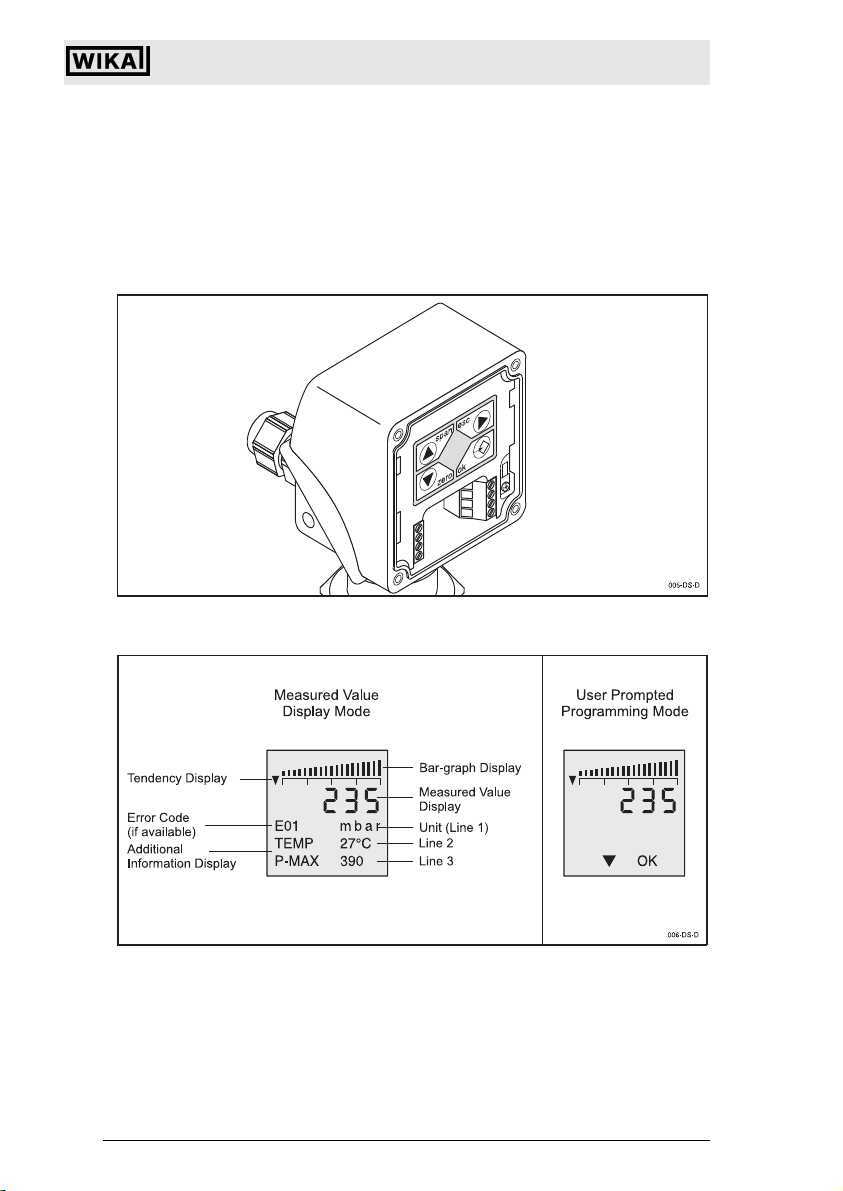
The measured-value indicator has four digits (in a 7-segment display) + symbols. Below it, is line 1 (16-segment display) used to display error codes and the signal’s unit
of measure. The unit of measure can be selected by the operator. Measurements
over 9999 can not be correctly displayed. Please note this when choosing the unit
(e.g. 9999 Pascal = 0,09999 bar). Additional information is displayed in lines 2 and 3
(16-segment display). The operator can enter commands in the programming mode
on the display unit by means of menu guided, clear-text prompts.
Subject to c hange due to techni cal modifications . © Copyright W IKA Alexander Wieg and GmbH & Co. KG / Germany
WIKA Alexander Wiegand GmbH & Co. KG· Alexander-Wiegand-Str. · 63911 Klingenberg · (09372) 132 - 710 · Fax - 706 · E-mail: support-tronic@wika.de · www.wika.de
98
2266939.05 D/GB 06/2006
Page 24

Universal IS Pressure Transmitter UniTrans
Product Description
Transmitters with displays offer a larger number of programming and processing options. These options include alarm status, damping, signal inversion, tank linearization and diagnostic messages.
Display units can be easily upgraded (see chapter 7.2).
5.2 Function
The pressure transducer converts the existing pressure into an electrical signal. Microelectronics further process the input signal and produce a proportional 4-20 mA
standard signal.
The display-version allows programming (parameterization) and the display of extended functions such as inversion, damping, alarm status and linearization.
5.2.1 Functions of Transmitters without Displays
• Calibration of zero and span under pressure (see 8.3)
• Calibration of zero and span without pressure (dry adjustment) (see 8.4)
• Setting the dampening / integration of the output signal 0-40 s (see 8.5)
• Reset to manufacturer’s default values (see 8.6)
• Mounting correction of the sensor (beginning with software version 1.05, see 8.4.3)
5.2.2 Functions of Transmitters with Displays
• Settable units of measurement (mbar, bar, psi, mA, %, m, mm WS) (see 9.5.1)
• Volume-related unit of measuring value can be set (l, kg, t, m
• Temperature and Min/Max values shown in display (see 9.5.1)
• Nominal pressure range of the sensor shown in display (see 9.5.1)
• Zero and span calibration (with/without pressure) (see 9.5.2)
• Setting of damping / integration of output signal 0-40 s (see 9.5.3)
• Inversion of the output current signal (see 9.5.3)
• Setting the output current value in case of alarm (3.6 mA or 21 mA) (see 9.5.3)
• Setting the limits of the output signal (see 9.5.3)
• Offset of the output signal (see 9.5.3)
• Mounting correction of the sensor (beginning with software version 1.05, see 8.4.3)
• Measuring circuit test function (see 9.5.4)
• Reset functions (see 9.5.4)
• Password activation (see 9.5.4)
• Selecting the language of the display (see 9.5.5)
• Entering of a table function for the linearization of the output signal (see 9.5.6)
• Entering the medium density (see 9.5.6)
3
, gal, lb) (see 9.5.1)
2266939.05 D/GB 06/2006
Subject to c hange due to techni cal modifications . © Copyright W IKA Alexander Wieg and GmbH & Co. KG / Germany
WIKA Alexand er Wiegand GmbH & Co. KG · Alexa nder-Wiegand-Str . · 63911 Klingen berg · (09372) 1 32 - 710 · Fax - 7 06 · E-mail: sup port-tronic@wik a.de · www.wika. de
99
Page 25

Universal IS Pressure Transmitter UniTrans
Product Description
5.2.3 Functional features of transmitters with HART-Communication
Universal commands
• Displayed unit can be set (mbar, bar, psi, mA, %, m, mm WS ...)
(see chapter 10.2.3)
• Definition of measuring site description and tag number (see 10.2.3)
• Measuring circuit test function (see 10.2.8)
• Temperature and min. / max values can be displayed (see chapter 10.2.3)
• Nominal pressure range of sensor can be displayed (see chapter 10.2.3)
• Cyclic measurement and transmission of the measured value (see chapter 10.2.3)
Common commands
• Calibration of zero point and span (under/without pressure) (see chapter 10.2.4)
• Adjustment of damping/integration of the output signal 0 s ... 40 s
(see chapter 10.2.5)
Device-specific commands
• Inversion of output current signal (see chapter 10.2.5)
• Adjustment of alarm values for the output current (3.6 mA or 21 mA)
(see chapter 10.2.5)
• Adjustment of output signal limits (see chapter 10.2.5)
• Mounting correction of the sensor (see chapter 10.2.7)
• Reset functions (see chapter 10.2.7)
• Password activation (see chapter 10.2.7)
• Setting up a table function for a linearisation of the output signal (see 10.2.6)
• Entering the medium density (see chapter 10.2.6)
• Volume-related units of measured value can be set (l, kg, t, m3, gal, lb) (see 10.2.3)
• Display and graphical illustration of the measuring value over time (see 10.2.10)
Subject to c hange due to techni cal modifications . © Copyright W IKA Alexander Wieg and GmbH & Co. KG / Germany
WIKA Alexander Wiegand GmbH & Co. KG· Alexander-Wiegand-Str. · 63911 Klingenberg · (09372) 132 - 710 · Fax - 706 · E-mail: support-tronic@wika.de · www.wika.de
100
2266939.05 D/GB 06/2006
Page 26

Universal IS Pressure Transmitter UniTrans
Product Description
5.3 Installation Examples
The UniTrans is primarily used to monitor the pressure in pipes, technical equipment
and tanks. Depending on the pressure range pressures between 20 mbar up to 4000
bar can be measured. The pressure is measured using absolute (against a vacuum)
or relative (against external or air pressure) measurement depending on the type of
sensor selected.
The UniTrans is also used for hydrostatic pressure measurement within liquid filled
pipes and containers.
Process Pressure Measurement: Process Pressure Measurement:
Used to measure pressure of liquids Used to measure container pressure.
or gases in pipelines.
Process Pressure Measurement: Process Pressure Measurement:
Installed behind feed pumps for Installed in front of and behind the filter.
process control or monitoring of pump Uses the pressure differential for moni-
functions. toring the function or accumulation of dirt
in the filter. Both output signals are pro-
2266939.05 D/GB 06/2006
Subject to c hange due to techni cal modifications . © Copyright W IKA Alexander Wieg and GmbH & Co. KG / Germany
WIKA Alexand er Wiegand GmbH & Co. KG · Alexa nder-Wiegand-Str . · 63911 Klingen berg · (09372) 1 32 - 710 · Fax - 7 06 · E-mail: sup port-tronic@wik a.de · www.wika. de
cessed by a PLC or signal converter.
101
Page 27

Universal IS Pressure Transmitter UniTrans
Product Description
Level Control: Level Control:
Externally mounted Combined pressure and head pressure
(with front flat diaphragm) are measured by two externally mounted
pressure transducers. The two signals
are analyzed and the differential is cal-
culated by a PLC or suitable signal
converter.
Subject to c hange due to techni cal modifications . © Copyright W IKA Alexander Wieg and GmbH & Co. KG / Germany
WIKA Alexander Wiegand GmbH & Co. KG· Alexander-Wiegand-Str. · 63911 Klingenberg · (09372) 132 - 710 · Fax - 706 · E-mail: support-tronic@wika.de · www.wika.de
102
2266939.05 D/GB 06/2006
Page 28

6 Technical Data
6.1 Input-values
Universal IS Pressure Transmitter UniTrans
Technical Data
Pressure Ranges
(Absolute pressure upon request)
6.2 Output-values
Output signal 4 ... 20 mA, two-wire, optionally with
Accuracy [% of span]
(incl. non-linearity, hysteresis, nonrepeatability, zero signal and full
scale error)
/ overpressure limit / Burst pressure
0 ... 0.4 bar 2 2.4
0 ... 1,6 bar 10 12
0 ... 6 bar 35 42
0 ... 16 bar 80 96
0 ... 40 bar 80 400
0 ... 100 bar 200 800
0 ... 250 bar 500 1200
0 ... 600 bar 1200 2400
0 ... 1.000 bar 1500 3000
0 ... 1,600 bar 2000 4000
0 ... 2,500 bar 3000 5000
0 ... 4,000 bar 4400 7000
-1 ... +0 bar* 2 2.4
-1 ... +0,6 bar* 10 12
-1 ... +3 bar* 35 42
-1 ... +5 bar* 35 42
-1 ... +15 bar* 80 96
* only relative pressure
Do not exceed the nominal pressure!
modulated HART signal
<
0.10 at ranges < 1000 bar
0.30 at ranges > 1000 bar
<
Non-linearity < 0.05% of span (BFSL) per IEC 61298-2
at ranges <
0.20% of span at ranges > 1000 bar
<
1000 bar
Turn down behavior: (1/k)
up to 1 : 5
1 : 5 to 1 : 20
no changes of deviation
the accuracy must be multiplied by the
factor (turn down / 5)
example for TD = 1:15, (k = 15)
accuracy = 0.10 * (15/5) = 0.3
2266939.05 D/GB 06/2006
Subject to c hange due to techni cal modifications . © Copyright W IKA Alexander Wieg and GmbH & Co. KG / Germany
WIKA Alexand er Wiegand GmbH & Co. KG · Alexa nder-Wiegand-Str . · 63911 Klingen berg · (09372) 1 32 - 710 · Fax - 7 06 · E-mail: sup port-tronic@wik a.de · www.wika. de
103
Page 29

Universal IS Pressure Transmitter UniTrans
Technical Data
Overall deviation
(at +10 °C ... +40 °C)
Load R
Fault signal 3.6 mA or 21 mA, programmable
Integration time 0 s, 1 s, 5 s, 20 s, 40 s, programmable
Adjustment of the span Up to Turn Down 1 : 20
Integrated lightning protection optional
Zero point adjustment -2.5 ... 99 %
6.3 Construction
Process connections
Model IUT-10
better than 0.15 % of span for pressure
ranges of <
1000 bar
better than 0.6 % for pressure ranges of
> 1000 bar
< (UB–12 V)/0.023 A
A
with R
in Ohm and UB in Volt
A
G 1/2 per EN 837 (max. 1600 bar)
1/2 NPT per "nominal size for US
standard tapered pipe
thread NPT"
(max. 1600 bar)
M 16 x 1,5 with sealing cone
1600 bar)
(>
M 20 x 1,5 with sealing cone
(>
1600 bar)
9/16 - 18 UNF innen F 250-C
(>
1600 bar)
Model IUT-11
G 1 flush diaphragm with o-ring
(0 ... 0.4 up to 0 ... 1.6 bar)
G 1/2 flush diaphragm with o-ring
(0 ... 6 bis 0 ... 600 bar)
G 1 1/2 flush diaphragm with o-ring
(0 ... 0.4 bis 0 ... 16 bar)
Model IUT-11 EHEDG version
G 1 flush diaphragm with o-ring
(0...0.4 bis 0...16 bar)
Subject to c hange due to techni cal modifications . © Copyright W IKA Alexander Wieg and GmbH & Co. KG / Germany
WIKA Alexander Wiegand GmbH & Co. KG · Alexand er-Wiegand-Str. · 6391 1 Klingenberg · (09372) 132 - 710 · Fax - 706 · E-mail: support-tronic@wika.de · www.wika.de
104
2266939.05 D/GB 06/2006
Page 30

Universal IS Pressure Transmitter UniTrans
Materials
Housing
Wetted parts (IUT-10)
(IUT-11)
Wetted parts (IUT-11 EHEDG version)
Internal transmission fluid
Technical Data
highly resistive, fiberglass-enforced
plastic (PBT); optionally aluminium
CrNi-steel 1.4571 and 2.4711
CrNi-steel 1.4571, o-ring: NBR {Viton or
EPDM}; {Hastelloy C4}
CrNi-steel 1.4435
Standard {Halocarbon oil for oxygenapplications}; {FDA-approved}
Electrical connection
per EN 60 529/ IEC529
Electric protection Reverse polarity, overload and short cir-
6.4 Auxilliary Power
Power supply 12 ... 36 V DC
Attention
6.5 Ambient Conditions
Ambient temperature – 40 °C ... + 85 °C
M 20 x 1.5 cable gland with internal
terminal block. For the dust approval
version, only cable glands and blind plugs
with the appropriate ATEX approval may
be used.
M12x1 plug, 4-pin (pin allocation: 1+ 3-)
(not in conjunction with dust approval)
[3/4" NPT female conduit (only with
aluminum case)]
(see 7.4)
cuit protection
Please consider the safety related
values according to EC-Type
Examination Certificate (see chapter 3)
°F = (°C * 1.8) + 32
(– 20 °C ... 70 °C with display)
Please consider the safety related val-
ues according to EC-Type Examination
Attention
2266939.05 D/GB 06/2006
Subject to c hange due to techni cal modifications . © Copyright W IKA Alexander Wieg and GmbH & Co. KG / Germany
WIKA Alexand er Wiegand GmbH & Co. KG · Alexa nder-Wiegand-Str . · 63911 Klingen berg · (09372) 1 32 - 710 · Fax - 7 06 · E-mail: sup port-tronic@wik a.de · www.wika. de
Certificate (see chapter 3)
105
Page 31

Universal IS Pressure Transmitter UniTrans
Storage temperature – 40 °C ... + 85 °C
(– 35 °C ... 80 °C with display)
Climate class D per DIN IEC 654-1
Technical Data
Ingress protection per EN 60 529 IP 65 for plastic case
IP 67 for aluminium case
EMC per EN 50 081-2, EN 50 082-2,
NAMUR NE 21
6.6 Process Conditions
Medium temperatures – 30 °C ... + 105 °C
Please consider the safety related
values according to EC-Type
Attention
Examination Certificate (see chapter 3)
6.7 Safety-related nominal values for IS protection conditions
-protection: The instruments are approved for IS zones, which require the
categories 1/2G, 2G,3G.
Dust approval 1/2D, 2D, 3D is available as an option.
Output signal 4 ... 20 mA, two-wire, optionally with
modulated HART signal
Ignition protection class
Available as an option
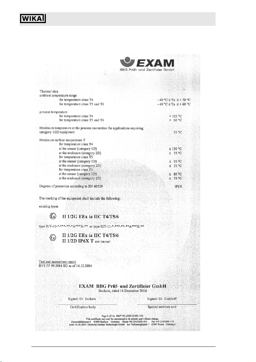
EEx ia IIC T4 EEx ia IIC T5 / T6
IP 6X T130°C / 95°C / 80°C
Certificate no. (display) (DMT 99 ATEX E 091 U)
°F = (°C * 1.8) + 32
Certificate no. (pressure transmitter) (DMT 99 ATEX E 093)
Power supply Ui 30 V DC 30 V DC
Short-circuit current Ii 100 mA 93 mA
Maximum load Pi 750 mW 697 mW
Medium temperature -40°C ... +105°C -40°C ... +60°C
Ambient temperature -40°C ... +70°C -40°C ... +60°C
Internal capacity Ci 9 nF
Internal inductivity Li very small
Subject to c hange due to techni cal modifications . © Copyright W IKA Alexander Wieg and GmbH & Co. KG / Germany
WIKA Alexander Wiegand GmbH & Co. KG · Alexand er-Wiegand-Str. · 6391 1 Klingenberg · (09372) 132 - 710 · Fax - 706 · E-mail: support-tronic@wika.de · www.wika.de
106
2266939.05 D/GB 06/2006
Page 32

Please pay attention to the information in chapter 7.4.
6.8 Product labels (example)
Universal IS Pressure Transmitter UniTrans
Technical Data
2266939.05 D/GB 06/2006
Subject to c hange due to techni cal modifications . © Copyright W IKA Alexander Wieg and GmbH & Co. KG / Germany
WIKA Alexand er Wiegand GmbH & Co. KG · Alexa nder-Wiegand-Str . · 63911 Klingen berg · (09372) 1 32 - 710 · Fax - 7 06 · E-mail: sup port-tronic@wik a.de · www.wika. de
107
Page 33

Universal IS Pressure Transmitter UniTrans
7 Installation
The device should be installed/operated in accordance with the regulations of ElexV,
the Device Safety Regulation, this operating manual and generally recognized
industry standards.
Before mounting the transmitter make sure to read the operating manual,
as well as the EC-type examination certificate.
Warning
7.1 Pressure Transmitter Installation
The pressure transmitter’s diaphram should not come into contact with
hard or sharp objects.
Warning
Installation Using a Weld-on Adapter:
• Insert a filler piece (a pressure transmitter dummy) into the weld-on adapter.
• Weld the adapter into the container/pipe wall (section-weld process).
• Remove the filler piece.
• Install the pressure transmitter in the weld-on adapter.
7.2 Display Unit Upgrades
The display unit can be easily upgraded at any time.
• Remove the housing cover and the supporting string.
• Attach the display unit’s supporting string to the same place.
• Plug the display unit’s connector into the appropriate jack.
Installation
When installing the display unit, make sure that the connection cable
and the supporting string are not kinked or pinched. If the cable is
Warning
damaged, correct function may be impaired..
On Model IUT the Ex-protection of the transmitter will no longer exist.
Only the model A-IRU can be mounted as display for upgrading .
• The display unit can be mounted at 90° angles.
• Fasten the display unit with screws.
Subject to c hange due to techni cal modifications . © Copyright W IKA Alexander Wieg and GmbH & Co. KG / Germany
WIKA Alexander Wiegand GmbH & Co. KG · Alexand er-Wiegand-Str. · 6391 1 Klingenberg · (09372) 132 - 710 · Fax - 706 · E-mail: support-tronic@wika.de · www.wika.de
108
2266939.05 D/GB 06/2006
Page 34

Universal IS Pressure Transmitter UniTrans
Connection Cable
Supporting String
•
All functions are programmable once the pressure transmitter has been upgraded
with a display unit. The adjusted parameters are stored after the display unit is removed.
The display unit can be rotated in 300°, so that it can be read under various installation
conditions. The housing cover with built-in display can be fastened to the housing at
all four side positions.
7.3 Housing Reconfiguration
Rotate the housing of the display unit in order to be able to read the display from
above when the pressure transmitter is installed in an upright position.
• Loosen the 4 internal hexagonal screws.
• Lightly lift off the housing with the display unit.
• Carefully turn the housing by 180°.
• Re-tighten the screws.
When tightening the 4 hollow screws, make sure that they are
adequately and securely seated in order to ensure that the transmitter is
Warning
properly sealed.
Installation
When reconfiguring the housing, the spiral cable must not be damaged.
2266939.05 D/GB 06/2006
Subject to c hange due to techni cal modifications . © Copyright W IKA Alexander Wieg and GmbH & Co. KG / Germany
WIKA Alexand er Wiegand GmbH & Co. KG · Alexa nder-Wiegand-Str . · 63911 Klingen berg · (09372) 1 32 - 710 · Fax - 7 06 · E-mail: sup port-tronic@wik a.de · www.wik a.de
109
Page 35

7.4 Electrical Connection
Universal IS Pressure Transmitter UniTrans
Installation
For the dust approval version, only cable glands and blind plugs with the
appropriate ATEX approval may be used. The M12x1 plug may not be used
Warning
in conjunction with dust approval.(See chapter 2.2)
Please observe local installation regulations (Germany: VDE-Standard).
The terminal voltage should not exceed 30 V.
The transmitter is only to be connected to approved intrinsically safe
measuring instruments.
The supply voltage is between 12 and 30 V. The power supply and the output signal
are transmitted via a two-wire cable (max. 12 mm outer diameter, max. 14 AWG) and
connected in accordance with the pin configuration.
When selecting a cable make sure that it complies with the capacity and
inductivity values as well as the voltage resistance values
Warning
(see “Technical Data” on page 103).
The given operating temperatures must not be exceeded.
For the connection of the cable the leads must be covered by end bushings. The cable must not be damaged.
Supply voltage can be supplied by a power unit, a transmitter power supply or by
means of a PLC connection.
It is suggested to use a model with integrated lightning protection for preventing
damage due to voltage peaks.
Subject to c hange due to techni cal modifications . © Copyright W IKA Alexander Wieg and GmbH & Co. KG / Germany
WIKA Alexander Wiegand GmbH & Co. KG · Alexand er-Wiegand-Str. · 6391 1 Klingenberg · (09372) 132 - 710 · Fax - 706 · E-mail: support-tronic@wika.de · www.wika.de
110
2266939.05 D/GB 06/2006
Page 36

Terminal Configuration
Universal IS Pressure Transmitter UniTrans
Installation
Hazardous (classified)areaNon-hazardous area
Legend
Ground
L- Negative
L+ Positive
I Test circuit; connect the ampere meter between terminals L+ and I
For transmitters with M12 x 1 circular connector, below are the wiring details:
1Positive
3 Negative
When connecting the clamps ’L+’ and ’I’ the safety-related nominal values
(See chapter 6.7) must be observed.
Warning
Only approved intrinsically safe ammeters may be connected to the test
circuit between the clamps ’L+’ and ’I’.
The internal resistance of the multimeter must be < 100
Ω.
The unit must be properly grounded in order to guarantee EMC resistance.
7.5 Pressure Compensation when using a Relative Pressure Sensor
A Goretex diaphram is used to compensate for the atmospheric pressure under the
IP 65 Protection Method.
A special cable with capillaries for relative pressurization is used for
Ingress Protection IP 67.
2266939.05 D/GB 06/2006
Subject to c hange due to techni cal modifications . © Copyright W IKA Alexander Wieg and GmbH & Co. KG / Germany
WIKA Alexand er Wiegand GmbH & Co. KG · Alexa nder-Wiegand-Str . · 63911 Klingen berg · (09372) 1 32 - 710 · Fax - 7 06 · E-mail: sup port-tronic@wik a.de · www.wik a.de
111
Page 37

Universal IS Pressure Transmitter UniTrans
Operation of Devices without Displays
8 Operation of Devices without Displays
8.1 Preparation
This unit can be programmed before or after installation.
• Connect an ampere meter to the device’s output (between terminals I and L+).
• Note that after each action, a brief oscillation/deflection of 20 mA occurs (verification of a successful action).
The following functions can be programmed without a display unit:
• Zero point adjustment with a full or empty container (with/without pressure)
• Span adjustment with a full or empty container (with/without pressure)
• Integration time
• Mounting correction of the sensor (beginning with software version 1.05)
• Reset to manufacturer’s defaults
An error signal is caused by a current surge (21 mA or 3.6 mA; 5 sec) when
the zero point or span setting fall outside of the sensor’s nominal pressure
range during adjustments with existing pressure. No values are stored.
The keypad becomes inactive after 10 min. of disuse. All settings will default to previously stored values. Only settings that have been confirmed
with the "OK" function are stored.
8.2 Key Functions (only for transmitters without display)
Function 1 Function 2
Basic setting,
store span (2 s)
Action: upward,
increase value
Basic setting,
store zero point
Action: downward,
decrease value
(2 s)
Exit key or programming mode
(2 s)
Verification
(store 2 s)
Activate keys
(push simulta-
neously for 2 sec.)
Mounting correc-
tion of the sensor
(push simulta-
neously for 2 sec.)
Basic setting
Integration time/
damping (push
Reset to default
(push simulta-
neously for 2 sec.)
simultaneously for
2 sec.)
Subject to c hange due to techni cal modifications . © Copyright W IKA Alexander Wieg and GmbH & Co. KG / Germany
WIKA Alexander Wiegand GmbH & Co. KG · Alexand er-Wiegand-Str. · 6391 1 Klingenberg · (09372) 132 - 710 · Fax - 706 · E-mail: support-tronic@wika.de · www.wika.de
112
2266939.05 D/GB 06/2006
Page 38

8.3 Calibration with Pressure
8.3.1 Zero Point Calibration
Make sure that the pressure to be used as the zero point (P 0 %), is
present at the transmitterer diaphragm before calibration.
Calibration Value
(2 sec.)
Universal IS Pressure Transmitter UniTrans
Operation of Devices without Displays
Confirm
(2 sec.)
Function
(2 sec.)
meas
Zero point calibration
8.3.2 Span Calibration
Calibration of the measurement range (span).
Make sure that the pressure to be used as the span end-point (P 100 %) is
present at the transmitter diaphragm. The measuring range between zero
and end value of span is saved as span.
Calibration Value
Calibration of span
A change in the zero point has no effect on the calibrated span.
However, if the span end-point is higher than the peak value of the sensor’s nominal pressure range, then span end-point is fixed at this peak value and the span is reduced accordingly.
A change in the span setting has no effect on the zero point. The zero point
and span end-point must fall within the sensor’s nominal pressure range.
A mounting correction must not be carried out when making an adjustment
with pressure (wet adjustment). Otherwise, the mounting correction must
be carried out before saving the zero point and the end value of span.
024-DS-GB
Confirm
Function
(2 sec.)(2 sec.)
(2 sec.)
meas
025-DS-GB
2266939.05 D/GB 06/2006
Subject to c hange due to techni cal modifications . © Copyright W IKA Alexander Wieg and GmbH & Co. KG / Germany
WIKA Alexand er Wiegand GmbH & Co. KG · Alexa nder-Wiegand-Str . · 63911 Klingen berg · (09372) 1 32 - 710 · Fax - 7 06 · E-mail: sup port-tronic@wik a.de · www.wik a.de
113
Page 39

Universal IS Pressure Transmitter UniTrans
Operation of Devices without Displays
8.4 Calibration without Pressure
Determine the current reference values for the zero point and the span to be entered
in the transmitter before calibration. This is done as follows:
8.4.1 Zero Point Calibration
• Determine the hydrostatic pressure of the liquid’s surface that meets the zero point.
• Adjust this pressure in proportion to the sensor’s nominal pressure range.
• Multiply this proportion by 16 mA and add 4 mA to the result.
This produces the calculated current (value I
and used to programm the zero point (0%).
Example:
A pressure transducer with 0 ... 400 mbar (nominal pressure) needs to be programmed.The liquid’s surface (with a density of 1) is 1 m above the diaphragm at the
zero point producing a pressure of 100 mbar.
Zero point pressure (0%) 100 mbar
-------------------------------------------------------------- ----------------------------------
calc
Sensors nominal pressure 400 mbar
This means that the device’s current value must be set to 8 mA when performing a dry
(empty) calibration.
), which is entered in the transmitter
calc
16 mA 4 mA
+⋅ 8 mA==
Calibration Value
calc
Calibration of zero point, without display, without pressure
(2 sec.)
(2 sec.)
... to I
... to I
Calibration Value
meas=Icalc
meas=Icalc
8.4.2 Span Calibration
• Determine the hydrostatic pressure of the liquid’s surface, which corresponds to the
span end-point.
• Calculate the difference of the pressure value between span end-point and zero
point and divide this difference by the nominal pressure range of the sensor.
• Multiply this proportion by 16 mA and add 4 mA to the result.
This produces the calculated current (value I
), which is entered in the transmitter
calc
and used to program the span end-point (100%).
The measurement range between zero point and span end-point will be stored as
span.
Subject to c hange due to techni cal modifications . © Copyright W IKA Alexander Wieg and GmbH & Co. KG / Germany
WIKA Alexander Wiegand GmbH & Co. KG · Alexand er-Wiegand-Str. · 6391 1 Klingenberg · (09372) 132 - 710 · Fax - 706 · E-mail: support-tronic@wika.de · www.wika.de
114
(2 sec.)
026-DS-GB
2266939.05 D/GB 06/2006
Page 40

Universal IS Pressure Transmitter UniTrans
Operation of Devices without Displays
Example:
A pressure transmitter with 0 ... 400 mbar (nominal pressure) is to be programmed.
The liquid’s surface (with a density of 1) is 1 m above the diaphragm at the zero point.
The maximum (span end-point) should be 3 m. The measuring range (span) is 200
mbar.
pressure difference (span) (300 mbar -100 mbar)
------------------- ------------------------------ --------------------------------- ----------------------------- ------------------ -
I
calc
Sensors nominal pressure 400 mbar
16 mA 4 mA
+⋅ 12 mA==
This means that the output must be set to 12 mA during programming.
Calculate
Calibration Value
I
=
calc
Activate
Keypad
(2 sec.)
Access
Function
(2 sec.)
Calibration of span, without display, without pressure
Enter
Value
current value increases
... to I
meas=Icalc
... to I
current value decreases
meas=Icalc
Calibration Value
A change in the zero point has no effect on the adjusted span.
However, if the span end-point is higher than the peak value of the
transmitter’s nominal pressure range, then the span end-point is fixed
at this peak value and the span is reduced accordingly.
A change in the span setting has no effect on the zero point. The zero
point and span end-point must fall within the transmitter’s nominal
pressure range.
A test / correction of the zero point is suggested after adjusting the
span in order to maintain optimum accuracy.
Important
A mounting correction should be carried out before or after making an
adjustment without pressure (dry adjustment) (see 8.4.3). The transmitter must therefore be placed in the reference position for the measurement (installation site) without pressure on the diaphragm.
Confirm
(2 sec.)
027-DS-GB
2266939.05 D/GB 06/2006
Subject to c hange due to techni cal modifications . © Copyright W IKA Alexander Wieg and GmbH & Co. KG / Germany
WIKA Alexand er Wiegand GmbH & Co. KG · Alexa nder-Wiegand-Str . · 63911 Klingen berg · (09372) 1 32 - 710 · Fax - 7 06 · E-mail: sup port-tronic@wik a.de · www.wik a.de
115
Page 41

Universal IS Pressure Transmitter UniTrans
Operation of Devices without Displays
8.4.3 Mounting correction of the sensor
The position of the measuring cell is entered by simultaneously pressing (2 sec.) the
"zero" and "esc" buttons.
Calibration Value
(2 sec.)
Mounting correction of the sensor
(2 sec.)
8.5 Integration Time (Damping) Adjustment
The following integration time settings can be used: 0, 1, 5, 20 and 40 s.
The sensor’s measured values can then be averaged using the adjusted integration
time.
Calibration Value
(2 sec.)(2 sec.)
4 times
Function
(2 sec.)
049-DS-GB
Calibration Value
(2 sec.)
Calibration of the integration time
Subject to c hange due to techni cal modifications . © Copyright W IKA Alexander Wieg and GmbH & Co. KG / Germany
WIKA Alexander Wiegand GmbH & Co. KG · Alexand er-Wiegand-Str. · 6391 1 Klingenberg · (09372) 132 - 710 · Fax - 706 · E-mail: support-tronic@wika.de · www.wika.de
116
028-DS-GB
2266939.05 D/GB 06/2006
Page 42

Universal IS Pressure Transmitter UniTrans
Operation of Devices without Displays
8.6 Reset to Default
All default data settings are restored by simultaneously pressing the "zero", "esc" and
the "ok" buttons for 2 seconds (see chapter 9.4)
Calibration Value
Reset to default
Important
Function
(2 sec.)
(2 sec.)
(2 sec.)
050-DS-GB
Calibrated special measurement ranges i. e. 4 bar on a 6 bar transmitter can be adjusted by factory pre-setting. A reset to default will reset
the sensor back to its nominal range (i. e. 6 bar). The factory pre-setting
gets lost.
2266939.05 D/GB 06/2006
Subject to c hange due to techni cal modifications . © Copyright W IKA Alexander Wieg and GmbH & Co. KG / Germany
WIKA Alexand er Wiegand GmbH & Co. KG · Alexa nder-Wiegand-Str . · 63911 Klingen berg · (09372) 1 32 - 710 · Fax - 7 06 · E-mail: sup port-tronic@wik a.de · www.wik a.de
117
Page 43

Universal IS Pressure Transmitter UniTrans
Operation of Transmitters with Display
9 Operation of Transmitters with Display
9.1 The Display
In order to program the device, remove the display with a screwdriver and re-attach it
to the housing as shown in the diagram below.
Subject to c hange due to techni cal modifications . © Copyright W IKA Alexander Wieg and GmbH & Co. KG / Germany
WIKA Alexander Wiegand GmbH & Co. KG · Alexand er-Wiegand-Str. · 6391 1 Klingenberg · (09372) 132 - 710 · Fax - 706 · E-mail: support-tronic@wika.de · www.wika.de
118
2266939.05 D/GB 06/2006
Page 44

Universal IS Pressure Transmitter UniTrans
Operation of Transmitters with Display
9.2 Key Functions
Button Functions
Main Menu Sub-menu Edit Functions
back to the previous
menu option
back to the previous
menu option
increase value
forward to next menu
option
back to value display
without saving
forward to next menu
option
back to main menu
without saving
decrease value
back without saving
to the sub-menu to the edit functions save value
activate keypad (push simultaneously; 2 s)
9.3 The Programming Mode
The transmitter can be programmed before or after installation.
The keypad is activated and the device can be programmed by simultaneously pressing the "esc" and "ok" keys (for 2 sec.). This method is used to access the main
menus. Each main menu has one or more sub-menus and each sub-menu, may have
its own sub-menus.
The keypad becomes inactive after 10 min. of disuse. All settings will default to previously stored values. Only settings that have been confirmed
with the "OK" function are stored.
A change in the starting measurement (zero point) has no effect on the
measurement span. Likewise, a change in the span has no effect on the
starting measurement.
An error signal occurs when the zero point or span settings fall outside of
the sensor’s nominal pressure range during calibration with pressure.
Nothing is saved.
2266939.05 D/GB 06/2006
Subject to c hange due to techni cal modifications . © Copyright W IKA Alexander Wieg and GmbH & Co. KG / Germany
WIKA Alexand er Wiegand GmbH & Co. KG · Alexa nder-Wiegand-Str . · 63911 Klingen berg · (09372) 1 32 - 710 · Fax - 7 06 · E-mail: sup port-tronic@wik a.de · www.wik a.de
119
Page 45

Universal IS Pressure Transmitter UniTrans
Operation of Transmitters with Display
9.4 Default Data (factory settings)
Function Defaults
Display Unit of measurement
(Line 1)
Line 2
Line 3
Calibration zero 4 mA
span 20 mA
Output Damping
Inversion
Fault
Limits
I-offset
Service password no active password
Service mounting correction not activated
Language English
Evaluation linear
density
Calibrated special measurement ranges i. e. 4 bar on a 6 bar transmitter can be adjusted by factory pre-setting. A reset to default will reset
Important
the sensor back to its nominal range (i. e. 6 bar). The factory pre-setting
gets lost.
Pressure display (in bar)
Temperature display (in °C)
Sensor’s nominal pressure range (in bar)
nom. pressure range start
nom. pressure range end
0 s
no
21 mA (upscale)
3.8 ... 20.5 mA
0 mA
yes
1 g/cm
3
Subject to c hange due to techni cal modifications . © Copyright W IKA Alexander Wieg and GmbH & Co. KG / Germany
WIKA Alexander Wiegand GmbH & Co. KG · Alexand er-Wiegand-Str. · 6391 1 Klingenberg · (09372) 132 - 710 · Fax - 706 · E-mail: support-tronic@wika.de · www.wika.de
120
2266939.05 D/GB 06/2006
Page 46

9.5 Main Menu
Universal IS Pressure Transmitter UniTrans
Operation of Transmitters with Display
DISPLAY
OPTIONS
CALIBRATION
RANGE
see chapter 9.5.1
see chapter 9.5.2
OUTPUT
DEFINITION
EVALUATION
FUNCTION
LANGUAGE
OPTIONS
SERVICE
FUNCTIONS
see chapter 9.5.3
see chapter 9.5.4
see chapter 9.5.5
(not available for
transmitters with
HARTCommunication
option)
see chapter 9.5.6
2266939.05 D/GB 06/2006
Subject to c hange due to techni cal modifications . © Copyright W IKA Alexander Wieg and GmbH & Co. KG / Germany
WIKA Alexand er Wiegand GmbH & Co. KG · Alexa nder-Wiegand-Str . · 63911 Klingen berg · (09372) 1 32 - 710 · Fax - 7 06 · E-mail: sup port-tronic@wik a.de · www.wik a.de
121
Page 47

9.5.1 Main Menu: Display
Universal IS Pressure Transmitter UniTrans
Operation of Transmitters with Display
DISPLAY
OPTIONS
*)The density of a medium must be
entered to calculate the correct filllevel when displaying or adjusting the
level in height units (e.g. mm, m, feet,
inch) (see 9.5.6). For ranges which
require over 4 digits see chapter
5.1.3.
**)For volume-based units it is necessary to enter the reference value
(100% = 0.0, value range 0 ...
3000).
*)
mbar
UNIT
DISPLAYED
DISPLAY
ROW 2
UNIT
UNIT
mmHG
UNIT
l
UNIT
lb
ROW 2
MEASURE
see *)
see **)
Units are set for the
measured value.
Units are set for the
measured value.
VOL_REF
100% = 0.0
OK
VOL_REF
100% = 0.0
OK
Second line
shows measured
value in %
Units are set for the
volume-related value.
Units are set for the
volume-related value.
bar
PSI
at
ROW 2
BLANK
Second line
remains empty
kg/cm²
mA
%
ROW 2
MIN VALUE
ROW 2
MEASUREMENT
Second line
shows minimum
values
mm
m starting with softinch ware version
1.05
feet
Pa
1)
hPa
kPa
ROW 2
MAX VALUE
ROW 2
TEMPERATUR
ROW 2
MEASUREMENT
TEMPERATU
TEMPERATURE
Second line
shows maximum
values
MPa
mmWS
mWS
1)
ROW 2
TEMPERATUR
TEMPERATU
mmHG
**)
TEMPERATURE
l
kg
ROW 2
TEMPERATURE
TEMPERATURE
in C
o
Second line
shows current
Tem p . in C
t starting with softm³ ware version
1.05
gal
lb
1) not available w. HART protocol
see chapter 5.1.3
ROW 2
CURRENT in mA
ROW 2
P-RANGE
TEMPERATURE
in F
o
Second line
shows present
current values
Merger of the
sensor's nominal
pressure range
Second line
shows current
Tem p . in F
display unit
Subject to c hange due to techni cal modifications . © Copyright W IKA Alexander Wieg and GmbH & Co. KG / Germany
WIKA Alexander Wiegand GmbH & Co. KG · Alexand er-Wiegand-Str. · 6391 1 Klingenberg · (09372) 132 - 710 · Fax - 706 · E-mail: support-tronic@wika.de · www.wika.de
122
o
o
Second line
shows minimum
o
Tem p . in C
Second line
shows minimum
o
Tem p . in F
Second line
shows maximum
o
Tem p . in C
Second line
shows maximum
o
Tem p . in F
031a1-DS-GB
2266939.05 D/GB 06/2006
Page 48

Universal IS Pressure Transmitter UniTrans
Operation of Transmitters with Display
DISPLAY
ROW 3
ROW 3
MEASURE %
ROW 3
BLANK
ROW 3
MIN VALUE
ROW 3
MAX VALUE
ROW 3
TEMPERATURE
ROW 3
CURRENT in mA
Third line
shows measured
value in %
Third line
remains empty
ROW 3
MEASUREMENT
ROW 3
TEMPERATURE
ROW 3
MEASUREMENT
ROW 3
TEMPERATURE
TEMPERATURE
o
in C
TEMPERATURE
o
in F
Third line
shows present
current value
Third line shows
minimum values
TEMPERATURE
in C
o
TEMPERATURE
o
in F
Third line shows
maximum values
TEMPERATURE
in C
o
TEMPERATURE
o
in F
Third line
shows current
o
Temp. in C
Third line
shows current
o
Temp. in F
Third line shows
minimum Temp.
o
in C
Third line shows
minimum Temp.
o
in F
Third line shows
maximum Temp.
o
in C
Third line shows
maximum Temp.
o
in F
ROW 3
P-RANGE
2266939.05 D/GB 06/2006
Subject to c hange due to techni cal modifications . © Copyright W IKA Alexander Wieg and GmbH & Co. KG / Germany
WIKA Alexand er Wiegand GmbH & Co. KG · Alexa nder-Wiegand-Str . · 63911 Klingen berg · (09372) 1 32 - 710 · Fax - 7 06 · E-mail: sup port-tronic@wik a.de · www.wik a.de
Merger of the
sensors's nominal
pressure range
123
Page 49

Universal IS Pressure Transmitter UniTrans
Operation of Transmitters with Display
9.5.2 Main Menu: Calibration of zero and span (with / without pressure)
MAIN MENU
CALIBRATION
CALIBRATE
RANGE
Important
CALIBRATE
WITH PRESSURE
CALIBRATE
WITHOUT
PRESSURE
CALIBRATE
SET ZERO
CALIBRATE
SET SPAN
CALIBRATE
DEFINE ZERO
CALIBRATE
DEFINE SPAN
Adjustment
Zero Point
Adjustment
Span
DEFINE ZERO
DEFINE SPAN
Adjustment zero point via entry
of a pressure value within the
nominal pressure range
Adjustment span via entry
of a pressure value within the
nominal pressure range
A single pressure value is set for the zero point or the span end-point
within the sensor’s nominal pressure range, and assigned to the associated output current signal when making adjustments with existing pressure. An error signal occurs when the existing pressure lies outside of
the sensor’s nominal pressure range. The value is not saved in this
case.
A mounting correction should be performed before or after making an
adjustment without pressure (dry adjustment) (see 8.4.3). The sensor
must therefore be placed in the reference position for the measurement
(installation site) without pressure on the diaphragm.
A mounting correction is unnecessary when making an adjustment with
pressure (wet adjustment). Otherwise, the mounting correction must be
performed before saving the zero point and span end- point.
A test / correction of the zero point is suggested after adjusting the
span in order to maintain optimum accuracy.
Important
Subject to c hange due to techni cal modifications . © Copyright W IKA Alexander Wieg and GmbH & Co. KG / Germany
WIKA Alexander Wiegand GmbH & Co. KG · Alexand er-Wiegand-Str. · 6391 1 Klingenberg · (09372) 132 - 710 · Fax - 706 · E-mail: support-tronic@wika.de · www.wika.de
124
2266939.05 D/GB 06/2006
Page 50

9.5.3 Main Menu: Output
Universal IS Pressure Transmitter UniTrans
Operation of Transmitters with Display
MAIN MENU
OUTPUT
OUTPUT
DEFINITION
OUTPUT
INVERSION
OUTPUT
DAMPING
OUTPUT
REVERSION
OUTPUT
ALARM/ERROR
OUTPUT
LIMITS
DAMPING
DAMPING
DAMPING
DAMPING
DAMPING
Output is inverted (20 mA ... 4 mA)
or not inverted (4 mA ... 20 mA)
LIMITS
Damping
40 s active
Damping
20 s active
Damping
5 s active
Damping
1 s active
Damping
0 s active
Alarm at 3.6 mA
(downscale)
Alarm at 21 mA
(upscale)
Measured value runs between 3.8 mA
and 20.5 mA. The current holds at the
limit when the sensing range is exceeded.
LIMITS
OUTPUT
CURRENT OFFSET
2266939.05 D/GB 06/2006
Subject to c hange due to techni cal modifications . © Copyright W IKA Alexander Wieg and GmbH & Co. KG / Germany
WIKA Alexand er Wiegand GmbH & Co. KG · Alexa nder-Wiegand-Str . · 63911 Klingen berg · (09372) 1 32 - 710 · Fax - 7 06 · E-mail: sup port-tronic@wik a.de · www.wik a.de
The current runs between 4 and 20 mA
Alarm condition when limits are reached;
It is necessary to restar t device by
using reset or by shutting down power
(see 8.5.6).
The output current is combined with an
assigned offset, which can have a maximum
of 0.4 mA.
Query routine for
additional safety.
033-DS-GB
125
Page 51

9.5.4 Main Menu: Evaluation
MAIN MENU
EVALUATION
Universal IS Pressure Transmitter UniTrans
Operation of Transmitters with Display
The level value and volume value
always be adjusted or verified in
order to store a value pair.
EVALUATION
FUCTIONS
EVALUATION
REF.TABLE
EVALUATION
LINEAR
EVALUATION
DENSITY
REF. POINT
INSERT
REF. POINT
DELETE
TABLE
EDIT
TABLE
ACTIVATE?
LINEAR
ACTIVATE?
l
d=
INSERT
DELETE
DELETE
DELETE
The preset
linearization table
is activated
The linear correlation
between input and
output is set
The density of
the medium is set
INSERT
The selected
tag (value pair)
is deleted
Entry of a new value pair
for the table used in
tank linearization
Entry of the level as a %
Entry of the associated
volume as a %
It is possible to enter up to
30 value pairs
The value pair for 0% (P0)
and 100% (P31) are fixed
The upper limit
can only be verified, not altered
Selected tag
(value pair:
level/volume)
is altered
The lower limit
can only be verified, not altered
Enter height values, which are each assigned a volumetric value of measure for tank
linearization. The linearization and the assignment of the 4 ... 20 mA output signal are
converted into tank volumes using this value pair.
When the evaluations function is activated the Turn down becomes
inactive.
Subject to c hange due to techni cal modifications . © Copyright W IKA Alexander Wieg and GmbH & Co. KG / Germany
WIKA Alexander Wiegand GmbH & Co. KG · Alexand er-Wiegand-Str. · 6391 1 Klingenberg · (09372) 132 - 710 · Fax - 706 · E-mail: support-tronic@wika.de · www.wika.de
126
2266939.05 D/GB 06/2006
Page 52

Universal IS Pressure Transmitter UniTrans
Operation of Transmitters with Display
Please check the following if "Wrong Entry" appears in the Evaluation
menu:
• whether or not more than 32 value pairs are entered in the table for tank
linearization (please note: P 0 and P 31 are fixed at 0% and 100% respectively)
• whether or not an existing height value was tried to be stored again
Example:
Level 100 %: 4000 mm
Density: 1 g/cm3
Density correction: 0.9 g/cm3
Span end point:
The span (end-point) must be re-calibrated (with or without pressure) to 4000 mm in
order to prevent a 4000 mm level tank from being overfilled.
Important
Please enter correct values.
000 mm 1 g/cm
----------------------------------------------------
⋅
0.9 g/cm
3
3
=
4444 mm
A change or correction in the density causes a change in the span endpoint’s unit of measure (mm, m, inch, feet). The span end-point must be
re-calibrated when changing the medium to be measured (due to a
change in density).
2266939.05 D/GB 06/2006
Subject to c hange due to techni cal modifications . © Copyright W IKA Alexander Wieg and GmbH & Co. KG / Germany
WIKA Alexand er Wiegand GmbH & Co. KG · Alexa nder-Wiegand-Str . · 63911 Klingen berg · (09372) 1 32 - 710 · Fax - 7 06 · E-mail: sup port-tronic@wik a.de · www.wik a.de
127
Page 53

9.5.5 Main Menu: Language
Universal IS Pressure Transmitter UniTrans
Operation of Transmitters with Display
The displayed language for transmitters with HART
-Communication is
always English. No other language can be selected.
Subject to c hange due to techni cal modifications . © Copyright W IKA Alexander Wieg and GmbH & Co. KG / Germany
WIKA Alexander Wiegand GmbH & Co. KG · Alexand er-Wiegand-Str. · 6391 1 Klingenberg · (09372) 132 - 710 · Fax - 706 · E-mail: support-tronic@wika.de · www.wika.de
128
2266939.05 D/GB 06/2006
Page 54

9.5.6 Main Menu: Service
MAIN MENU
SERVICE
Universal IS Pressure Transmitter UniTrans
Operation of Transmitters with Display
SERVICE
FUNCTIONS
MOUNTING
CORRECTION
SERVICE
LOOPTEST
SERVICE
DEVICE DATA
SERVICE
TIMER
SERVICE
RESET
Mounting correction is performed;
sensor must be correctly positioned /
mounted and without pressure.
CIRCUIT TEST
Hrs.-TOTAL
Hrs.-CALIBRATE
Hrs.-RESET
Hrs.-SENSOR
RESET
TIMER
RESET
MIN/MAX VALUES
RESET
ALL
The set current value is
used as the test signal until the
"esc" button is pressed
Total number of
operating hours.
Number of hours
since the last
calibration.
Number of hours
since the last
system Reset.
Number of hours
that sensor was in
operation.
Number of hours
since the last
Reset to zero.
Min/Max values
are reset.
RESET ALL
???
All values are reset
to the factory setting
(see 6.4)
RESET
ALARM
SERVICE
PASSWORD
2266939.05 D/GB 06/2006
Subject to c hange due to techni cal modifications . © Copyright W IKA Alexander Wieg and GmbH & Co. KG / Germany
WIKA Alexand er Wiegand GmbH & Co. KG · Alexa nder-Wiegand-Str . · 63911 Klingen berg · (09372) 1 32 - 710 · Fax - 7 06 · E-mail: sup port-tronic@wik a.de · www.wik a.de
PASSWORD
(DE)ACTIVE
Reset the alarm after exceeding
the 4/20 mA limit, necessary when
setting fixed limits 4/20 mA FIX (see 6.5.3)
ENTRY
A digital value between
0000 and 9999 is set as
the password.
129
Page 55

Universal IS Pressure Transmitter UniTrans
Transmitter Operation with HART®-functionality
10 Transmitter Operation with HART®-functionality
10.1 Possible HART® connections
Transmitters with HART
(HC 275), via PC with PactWare and HART
with HART
®
-ability (e.g. Pepperl+Fuchs HART®-Multiplexer or Pepperl+Fuchs RPI-
System).
10.1.1 Connection of the HART
The pressure transmitters IUT-10 and IUT-11 can be operated with the standard
menus of the HART
necessary. A specified DD can be ordered from WIKA.
®
-functionality can be operated via a HART®-hand terminal
®
- hand terminal
®
-operating unit. A special DD (Device Description) is not
®
-Modem, or with a remote-I/O-system
Hazardous
(classified) area
IUT-10 / IUT-11
4 mA ... 20 mA
HART® hand terminal
within the hazardous area
Non-hazardous
area
Transmitter power supply
e. g. KFD2-STC3-Ex.1
from Pepperl+Fuchs GmbH
4 mA ... 20 mA
HART® hand terminal
Connection with a HART® hand terminal within hazardous area
The termination resistor in the loop must have a
Warning
minimum value of 250
The HART
®
-hand terminal and its operation is described in the
Ω.
respective manual of the unit.
Further information about the connection via remote-I/O-systems with
®
-ability can be found in the respective system descriptions.
HART
PLC
> 250 W
045-DS-GB
Subject to c hange due to techni cal modifications . © Copyright W IKA Alexander Wieg and GmbH & Co. KG / Germany
WIKA Alexander Wiegand GmbH & Co. KG · Alexand er-Wiegand-Str. · 6391 1 Klingenberg · (09372) 132 - 710 · Fax - 706 · E-mail: support-tronic@wika.de · www.wika.de
130
2266939.05 D/GB 06/2006
Page 56

Universal IS Pressure Transmitter UniTrans
Transmitter Operation with HART®-functionality
10.1.2 Connecting the HART®-modem for PC operation
®
The HART
-modem connects the pressure transmitter with HART®-functionality with
the serial RS 232 C interface of a PC. In this constellation the parameters of the
pressure transmitter can be set via the software PACT
®
A respective HART
Hazardous
(Classified) area
Connection to the hazardous area via HART® Modem
modem can be ordered from WIKA.
IUT-10 / IUT-11
4 mA ... 20 mA
Transmitter power supply
e. g. KFD2-STC3-Ex.1
4 mA ... 20 mA
HART® modem
ware.
Non-hazardous
area
PC
PLC
> 250 W
046-DS-GB
Non-hazardous area
IUT-10 / IUT-11
4 mA ... 20 mA
HART modem
®
Connection to the non-hazardous
area via HART
2266939.05 D/GB 06/2006
Subject to c hange due to techni cal modifications . © Copyright W IKA Alexander Wieg and GmbH & Co. KG / Germany
WIKA Alexand er Wiegand GmbH & Co. KG · Alexa nder-Wiegand-Str . · 63911 Klingen berg · (09372) 1 32 - 710 · Fax - 7 06 · E-mail: sup port-tronic@wik a.de · www.wik a.de
®
Modem
PC
PLC
> 250 W
047-DS-GB
131
Page 57

Universal IS Pressure Transmitter UniTrans
Transmitter Operation with HART®-functionality
If the resistances of the devices connected to the power supply/signal line (voltage
source) are less than 250
power supply line. The sum of the internal capacitances and inductances of the components used must not exceed the highest permissible values of the ia IIC circuit.
IUT-10 / IUT-11
Ω, a minimum resistance of 250 Ω must be installed in the
Non-hazardous area
4 mA ... 20 mA
250 W
HART modem®
PC
+
-
Please note the different safety-related values according to the EC-type
examination certificate (see also chapter 6.7) and note the permissible
cable
Warning
length for devices with HART
in the loop must have a minimum value of 250
The necessary operating software
®
communication.The termination resistor
Ω.
PACTware is described
in chapter 10.2.
10.2 Operation via PC and the software PACT
The PACTware software with the necessary device driver (DTM) can be ordered
from WIKA. An integration in other HART
ware
®
management systems or FDT manage-
ment systems is possible.
051-DS-GB
Subject to c hange due to techni cal modifications . © Copyright W IKA Alexander Wieg and GmbH & Co. KG / Germany
WIKA Alexander Wiegand GmbH & Co. KG · Alexand er-Wiegand-Str. · 6391 1 Klingenberg · (09372) 132 - 710 · Fax - 706 · E-mail: support-tronic@wika.de · www.wika.de
132
2266939.05 D/GB 06/2006
Page 58

Universal IS Pressure Transmitter UniTrans
Transmitter Operation with HART®-functionality
10.2.1 Menu 'Device info'
The screen 'Device info' displays all important information of the transmitter,
which cannot be modified.
10.2.2 Menu 'Description'
In the fields of the menu 'Description' the name and description of the selected
instrument are given. The texts can be edited and saved in a file, but not in the
transmitter.
2266939.05 D/GB 06/2006
Subject to c hange due to techni cal modifications . © Copyright W IKA Alexander Wieg and GmbH & Co. KG / Germany
WIKA Alexand er Wiegand GmbH & Co. KG · Alexa nder-Wiegand-Str . · 63911 Klingen berg · (09372) 1 32 - 710 · Fax - 7 06 · E-mail: sup port-tronic@wik a.de · www.wik a.de
133
Page 59

Universal IS Pressure Transmitter UniTrans
Transmitter Operation with HART®-functionality
10.2.3 Submenu 'Parameter' - Device info
Polling address:
Address of the UniTrans in "short integer" format.
Change in dev.
Modify polling address in the transmitter
:
When this message pops up you should consider the described consequences and
then decide whether to change the address or stay with the actual address.
Long address:
38-bit-address as worldwide device-unique identifier
Tag:
The tag number is to be entered (identification code of measuring site)
Desc. of measurement point:
An explicit description of the measuring site is to be entered
Subject to c hange due to techni cal modifications . © Copyright W IKA Alexander Wieg and GmbH & Co. KG / Germany
WIKA Alexander Wiegand GmbH & Co. KG · Alexand er-Wiegand-Str. · 6391 1 Klingenberg · (09372) 132 - 710 · Fax - 706 · E-mail: support-tronic@wika.de · www.wika.de
134
2266939.05 D/GB 06/2006
Page 60

Universal IS Pressure Transmitter UniTrans
Transmitter Operation with HART®-functionality
Last parametrization:
Date of last parametrization
Unit of measured value:
Units of measured value:
• mbar, bar PSI, atm, mA, %, mm, m, inch, feet, Pa, kPa, Mpa, mmWS, mmHG
Volume-related units:
• l, kg, t, m
Reference:
The reference value of the volume-related units is only active when volume units have
been activated.
• 100% = 0,0 value range 0 ... 3000,0
Display row 2 / row 3:
Here the display of several temperature, pressure and min./max. values can be set.
3
, gal, lb
When height is displayed or calibrated (e. g. mm, m, feet, inch) the density value of the respective medium must be entered in order to calculate the correct filling level (see also chapter 10.2.6).
2266939.05 D/GB 06/2006
Subject to c hange due to techni cal modifications . © Copyright W IKA Alexander Wieg and GmbH & Co. KG / Germany
WIKA Alexand er Wiegand GmbH & Co. KG · Alexa nder-Wiegand-Str . · 63911 Klingen berg · (09372) 1 32 - 710 · Fax - 7 06 · E-mail: sup port-tronic@wik a.de · www.wik a.de
135
Page 61

Universal IS Pressure Transmitter UniTrans
Transmitter Operation with HART®-functionality
10.2.4 Submenu 'Parameter' - Calibration
Calibration with pressure:
The calibration with pressure is only possible when the cyclic measurement is activated.
Set zero:
Before starting the calibration make sure that the pressure applied to the transmitter
has the value you want to set as zero point (P 0 %).
Set span:
Make sure that the pressure applied to the transmitter has the value you want to set
as upper end of span (P 100 %). The measuring range between zero point and upper
end of span will be saved as span.
In general the preset span is not affected when the zero point is changed. When,
however, the zero point is increased in a way that the upper end of span would reach
beyond the maximum nominal pressure of the transmitter, this maximum nominal
pressure value is defined as new upper end of span and the span is reduced
respectively. A modification of the span settings does not affect the zero point.
During a calibration under pressure two pressure values are set respectively for zero
and upper end point of span. These values, which must lie within the nominal
pressure range of the transmitter are respectively assigned to an output current
signal. When the applied pressure lies beyond the nominal pressure range of the
transmitter an error message is displayed. In this case the value is not saved.
Cyclic measurement (measured value):
The actual measured value for the calibration under pressure is displayed
(automatic actualisation).
Subject to c hange due to techni cal modifications . © Copyright W IKA Alexander Wieg and GmbH & Co. KG / Germany
WIKA Alexander Wiegand GmbH & Co. KG · Alexand er-Wiegand-Str. · 6391 1 Klingenberg · (09372) 132 - 710 · Fax - 706 · E-mail: support-tronic@wika.de · www.wika.de
136
2266939.05 D/GB 06/2006
Page 62

Universal IS Pressure Transmitter UniTrans
Transmitter Operation with HART®-functionality
Calibration without pressure:
Zero:
• Here a pressure value within the nominal pressure range of the transmitter must be
entered.
Span:
• Here a pressure value for the span within the nominal pressure range of the trans-
mitter must be entered.
When calibrating without pressure (dry calibration), a sensor mounting
correction should be carried out before or after the calibration (see also
chapter 10.2.7 ). For this, the sensor must be placed in the reference
position for the measurement (mounting position) and must not be
under pressure.
When calibrating with pressure (wet calibration), the mounting correction is unnecessary, or it must be carried out before the zero point and
end of span are saved.
Nominal pressure range:
Here the sensor’s pressure range is displayed
2266939.05 D/GB 06/2006
Subject to c hange due to techni cal modifications . © Copyright W IKA Alexander Wieg and GmbH & Co. KG / Germany
WIKA Alexand er Wiegand GmbH & Co. KG · Alexa nder-Wiegand-Str . · 63911 Klingen berg · (09372) 1 32 - 710 · Fax - 7 06 · E-mail: sup port-tronic@wik a.de · www.wik a.de
137
Page 63

Universal IS Pressure Transmitter UniTrans
Transmitter Operation with HART®-functionality
10.2.5 Submenu 'Parameter' - Output
Damping:
An average value of the pressure values applied to the sensor is calculated over the
predefined integration time. The following integration times can be set:
• 0, 1, 5, 20 and 40 s.
Output inversion:
The output signal can be inverted or not inverted.
• inverted 20 ... 4 mA
• not inverted 4 ... 20 mA
Alarm/Error:
Here the current value is displayed, which is set for an error message:
• 21.0 mA (upscale) or
• 36 mA (downscale).
Output current limits:
Here the range of output current is set.
• 3.8 ... 20.5 mA
When the applied pressure rises beyond the nominal range the current value ends
at the set limit value.
• 4 ... 20 mA
When the applied pressure rises beyond the nominal range and the alarm goes off
a reset must be carried out, or the power supply must be cut
(see also chapter 10.2.7).
Subject to c hange due to techni cal modifications . © Copyright W IKA Alexander Wieg and GmbH & Co. KG / Germany
WIKA Alexander Wiegand GmbH & Co. KG · Alexand er-Wiegand-Str. · 6391 1 Klingenberg · (09372) 132 - 710 · Fax - 706 · E-mail: support-tronic@wika.de · www.wika.de
138
2266939.05 D/GB 06/2006
Page 64

Universal IS Pressure Transmitter UniTrans
Transmitter Operation with HART®-functionality
10.2.6 Submenu 'Parameter' - Evaluation
Evaluation:
Here the relation between height values and volume values is given in a graph.
Function:
• Linear:
Here a linear relation between height and volume values is set.
•
Table:
The values of the table are set as linearisation graph between height and volume
value.
For liquid level measurements in tanks, values of height (level) must be entered and
a respective volume is assigned to each value. These value pairs are used to determine the linear relationship and to assign the 4 mA ... 20 mA output signal to values
of tank volume (P 0 and P 31 are fixed at 0 % and 100 %).
2266939.05 D/GB 06/2006
Subject to c hange due to techni cal modifications . © Copyright W IKA Alexander Wieg and GmbH & Co. KG / Germany
WIKA Alexand er Wiegand GmbH & Co. KG · Alexa nder-Wiegand-Str . · 63911 Klingen berg · (09372) 1 32 - 710 · Fax - 7 06 · E-mail: sup port-tronic@wik a.de · www.wik a.de
139
Page 65

Universal IS Pressure Transmitter UniTrans
Transmitter Operation with HART®-functionality
Check lin. table:
The entered linearization table is subject to a plausibility check.
If wrong or incomplete values are entered the following error window pops up
Media density:
Here the density of the medium is given in g/cm³
The consequence of a correction or modification of the density value is that also the
respective values of the upper end of span are changed for the related measuring values (mm, m, inch, feet). In some cases after a media change (change of density) the
upper end of span must be recalibrated.
.
Subject to c hange due to techni cal modifications . © Copyright W IKA Alexander Wieg and GmbH & Co. KG / Germany
WIKA Alexander Wiegand GmbH & Co. KG · Alexand er-Wiegand-Str. · 6391 1 Klingenberg · (09372) 132 - 710 · Fax - 706 · E-mail: support-tronic@wika.de · www.wika.de
140
2266939.05 D/GB 06/2006
Page 66

Universal IS Pressure Transmitter UniTrans
Transmitter Operation with HART®-functionality
10.2.7 Window 'Service'
You can open the 'Service' window under 'Device' via the 'Service' menu item or in
the 'Context' menu (right mouse button) for the device that is selected in the
navigation window (project view).
The following warning will pop up while you browse to the window 'Service'. After
reading the information you can just confirm, or mark the check box below on the left
side 'Do not show this warning again'. Then the window 'Service' will open.
Password:
Activate / Deactivate
Via these fields the password function can be activated or deactivated. In both fields
the same four digits between 0000 and 9999 must be set.
When a password is activated transmitter settings can only be changed after the
password has been entered. In the case of a transmitter without display no settings
can be changed at the transmitter.
Mounting correction (Activate):
A mounting correction is carried out. Before the correction is activated the sensor
must be in mounting position and pressureless.
2266939.05 D/GB 06/2006
Subject to c hange due to techni cal modifications . © Copyright W IKA Alexander Wieg and GmbH & Co. KG / Germany
WIKA Alexand er Wiegand GmbH & Co. KG · Alexa nder-Wiegand-Str . · 63911 Klingen berg · (09372) 1 32 - 710 · Fax - 7 06 · E-mail: sup port-tronic@wik a.de · www.wik a.de
141
Page 67

Universal IS Pressure Transmitter UniTrans
Transmitter Operation with HART®-functionality
Timer:
• Hrs-TOTAL: display of overall operating hours
• Hrs-CALIB: display of operating hours since last calibration
• Hrs-RESET: display of operating hours since last reset
• Hrs-SENSOR: display of sensor operating hours
Reset:
Via the four buttons certain functions of the transmitter are reset.
• Timer: Reset of operating hours
• Alarm 4 - 20 mA: Alarm reset when the 4 ... 20 mA-limit has been exceeded
• MIN/MAX values: Reset of MIN/MAX-values in the display
• Reset all: Reset of all settable values to factory settings
(see also chapter 9.4)
Calibrated special measuring ranges i. e. 4 bar together with a 6 bar
Important
transmitter can be adjusted by factory pre-setting. A reset to default will
reset the sensor to its nominal range (i. e. 6 bar). The factory pre-setting
gets lost.
Subject to c hange due to techni cal modifications . © Copyright W IKA Alexander Wieg and GmbH & Co. KG / Germany
WIKA Alexander Wiegand GmbH & Co. KG · Alexand er-Wiegand-Str. · 6391 1 Klingenberg · (09372) 132 - 710 · Fax - 706 · E-mail: support-tronic@wika.de · www.wika.de
142
2266939.05 D/GB 06/2006
Page 68

Universal IS Pressure Transmitter UniTrans
Transmitter Operation with HART®-functionality
10.2.8 Window 'Simulation'
You can open the 'Simulation' window under 'Device' via the 'Simulation' menu item
or in the 'Context' menu (right mouse button) for the device that is selected in the
navigation window (project view).
The following warning will pop up while you browse to the window 'Simulation'.
After reading the information you can just confirm, or mark the check box below on
the left side 'Do not show this warning again'. Then the window 'Simulation' will
open.
During online operation, the measured value is given as a current output.
A set current value is given as a test signal until online operation is
selected.
Attention
Before changing and storing the parameter setting menu item
'Simulation' has to be closed.
2266939.05 D/GB 06/2006
Subject to c hange due to techni cal modifications . © Copyright W IKA Alexander Wieg and GmbH & Co. KG / Germany
WIKA Alexand er Wiegand GmbH & Co. KG · Alexa nder-Wiegand-Str . · 63911 Klingen berg · (09372) 1 32 - 710 · Fax - 7 06 · E-mail: sup port-tronic@wik a.de · www.wik a.de
143
Page 69

Universal IS Pressure Transmitter UniTrans
Transmitter Operation with HART®-functionality
10.2.9 Window 'Measured value'
You can open the 'measured value' window under 'Device' - 'Display' in the
'Measured value' menu item or in the 'Context' menu (right mouse button) for the
instrument that has been selected in the navigation window (project view).
Continuous display of actual current, temperature and measuring values
Before changing and storing the parameter setting menu item
'Measured value' has to be closed.
10.2.10 Window 'Trend'
You can open the 'trend' window under 'Device' - 'Display' via the 'Trend' menu item
or in the 'Context' menu (right mouse button) for the device that is selected in the
navigation window (project view).
This display provides information about the change of the measured value over time
(recorder function). The scale can be changed by clicking on the time or the scaling
axis.
Before changing and storing the parameter setting menu item 'Trend'
has to be closed.
Subject to c hange due to techni cal modifications . © Copyright W IKA Alexander Wieg and GmbH & Co. KG / Germany
WIKA Alexander Wiegand GmbH & Co. KG · Alexand er-Wiegand-Str. · 6391 1 Klingenberg · (09372) 132 - 710 · Fax - 706 · E-mail: support-tronic@wika.de · www.wika.de
144
2266939.05 D/GB 06/2006
Page 70

Universal IS Pressure Transmitter UniTrans
Transmitter Operation with HART®-functionality
10.2.11 Window 'Burst mode'
You can open the 'Burst mode' window in the 'Context' menu (right mouse button) for
the device that is selected in the navigation window (project view).
In the burst mode UniTrans sends actual values to the master on a cyclic basis.
• Current
• %-value and current
• Pressure, temperature and current
If Burst mode is active a parametrization is not possible.
10.2.12 Window 'Diagnosis'
You can open the 'Diagnosis' window under 'Device' - 'Display' via the 'Diagnosis'
menu item or in the 'Context' menu (right mouse button) for the device that is selected
in the navigation window (project view).
Possible errors and their short description are indicated (see also chapter 11).
Before changing and storing the parameter setting menu item
'Diagnosis' has to be closed.
2266939.05 D/GB 06/2006
Subject to c hange due to techni cal modifications . © Copyright W IKA Alexander Wieg and GmbH & Co. KG / Germany
WIKA Alexand er Wiegand GmbH & Co. KG · Alexa nder-Wiegand-Str . · 63911 Klingen berg · (09372) 1 32 - 710 · Fax - 7 06 · E-mail: sup port-tronic@wik a.de · www.wik a.de
145
Page 71

Universal IS Pressure Transmitter UniTrans
Diagnostics and Service
11 Diagnostics and Service
If a failure cannot be repaired, the transmitter must be switched off.The operator then must make sure that it is only switched on again after the failure
Attention
The following error messages can appear on devices with displays
(see chapter 5.1.3):
Error Code Error Error Correction Measures
E00 ROM-error Return device to manufacturer
E01 Power supply error Check power supply
E03
E04 Sensor’s temperature range was
E06 Sensor recognition Disconnect and reconnect power
E07 General communications error
E08
Sen Error 0 Sensor recognition Check the connection between
has been repaired.
Repairs should only be carried out by the manufacturer. All other repairs or
modifications are unauthorized.
2
PROM communications error
E
Disconnect and reconnect power
supply
Return sensor’s temperature to
exceeded
specified limits
supply
Check the connection between
between the sensor and the control interface unit
2
PROM
Error E
the sensor and the control inter-
face unit
send in transmitter for service
the sensor and the control inter-
face unit
12 Disposal
When storing or disposing the pressure transmitter, take precautions with
Important
Subject to c hange due to techni cal modifications . © Copyright W IKA Alexander Wieg and GmbH & Co. KG / Germany
WIKA Alexander Wiegand GmbH & Co. KG · Alexand er-Wiegand-Str. · 6391 1 Klingenberg · (09372) 132 - 710 · Fax - 706 · E-mail: support-tronic@wika.de · www.wika.de
146
regard to remaining media. Remaining media in the pressure port may
be hazardous or toxic!
Dispose of instrument components and packaging materials in
accordance with the respective waste treatment and disposal regulations
of the region or country to which the instrument was supplied.
2266939.05 D/GB 06/2006
Page 72

13 Appendix
13.1 Dimension Diagrams
Universal IS Pressure Transmitter UniTrans
Appendix
2266939.05 D/GB 06/2006
Subject to c hange due to techni cal modifications . © Copyright W IKA Alexander Wieg and GmbH & Co. KG / Germany
WIKA Alexand er Wiegand GmbH & Co. KG · Alexa nder-Wiegand-Str . · 63911 Klingen berg · (09372) 1 32 - 710 · Fax - 7 06 · E-mail: sup port-tronic@wik a.de · www.wik a.de
147
Page 73

Universal IS Pressure Transmitter UniTrans
Appendix
Subject to c hange due to techni cal modifications . © Copyright W IKA Alexander Wieg and GmbH & Co. KG / Germany
WIKA Alexander Wiegand GmbH & Co. KG · Alexand er-Wiegand-Str. · 6391 1 Klingenberg · (09372) 132 - 710 · Fax - 706 · E-mail: support-tronic@wika.de · www.wika.de
148
2266939.05 D/GB 06/2006
Page 74

Universal IS Pressure Transmitter UniTrans
Appendix
2266939.05 D/GB 06/2006
Subject to c hange due to techni cal modifications . © Copyright W IKA Alexander Wieg and GmbH & Co. KG / Germany
WIKA Alexand er Wiegand GmbH & Co. KG · Alexa nder-Wiegand-Str . · 63911 Klingen berg · (09372) 1 32 - 710 · Fax - 7 06 · E-mail: sup port-tronic@wik a.de · www.wik a.de
149
Page 75

Universal IS Pressure Transmitter UniTrans
Appendix
Subject to c hange due to techni cal modifications . © Copyright W IKA Alexander Wieg and GmbH & Co. KG / Germany
WIKA Alexander Wiegand GmbH & Co. KG · Alexand er-Wiegand-Str. · 6391 1 Klingenberg · (09372) 132 - 710 · Fax - 706 · E-mail: support-tronic@wika.de · www.wika.de
150
2266939.05 D/GB 06/2006
Page 76

Universal IS Pressure Transmitter UniTrans
Appendix
13.2 Model Key
Signal output
1R
2Sbar absolut bis 16 bar abs
3BK0 bar ... 16 bar / bar absolute
4CSchemical seal prices and designs according to chemical seals product range
5O
6AAluminium Ingress protection IP 67
7E-20 ... +60 °C (-4 ... +140 °F) only for oxygen version
8M
9A
10 C
11 1 Z quality certificates
12 T Z additional text
1) inclusive PACTware Starter Version for configuration
2) only with accuracy 0.5%; max. Turndown 2:1
3) max. temperature of medium 60°C
4) only in conjuction with aluminum case; not in conjuncction with electrical connection code M (M12x1 plug)
A 4 ... 20 mA, 2-wire
4 ... 20 mA with HART
Unit
B bar
Pressure range
CA -1 bar ... 0 bar BM 0 bar ... 40 bar
CD -1 bar ... 0,6 bar BO 0 bar ... 100 bar
CH -1 bar ... 3 bar BQ 0 bar ... 250 bar
CK -1 bar ... 5 bar BT 0 bar ... 600 bar
CP -1 bar ... 15 bar BU 0 bar ... 1000 bar
BB 0 bar ... 0.4 bar / bar abs olute BV
BE 0 bar ... 1.6 bar / bar ab solute BX
BH 0 bar ... 6 bar / bar absolute BZ
Process connection
GD G ½ B ML
ND ½ NPT MP M20 x 1.5 female, with sealing cone from 1600 bar
VZ 9/16 - 18 UNF female F 250-C from 1600 bar
Special design features
Z without
E oil and grease free
A
oxygen, oil and grease free
overvoltage protection according to IEC 801-5
Case material
M highly resistive, fiberglass-enforced plastic (PBT)
Temperature range of medium
T -30 ... +105 °C (-22 ... +221 °F)
Electrical connection
A cable gland M20x1.5 with internal terminal block standard
4 pin locki ng plug M 12x1
Digital displ ay
Z without
with integrated 4-digit LCD-display
Approvals
L EEx ia IIC T4-T6 in compliance with ATEX 100a II 1/2 G for connection to zone 0
X
EEx IP6X 1/2D, 2D + EEx ia IIC T4-T6 1/2G, 2G per ATEX
CSA
Additional order i nfo
YES NO
®
protocol, 2-wire
3)
1)
0 bar ... 1600 bar2only with aluminium case
0 bar ... 2500 bar2only with aluminium case
0 bar ... 4000 bar2only with aluminium case
M16 x 1.5 female, with sealing cone from 1600 bar
up to 1000 bar abs
4)
Order code:
IUT-10 - - - - -
2266939.05 D/GB 06/2006
Subject to c hange due to techni cal modifications . © Copyright W IKA Alexander Wieg and GmbH & Co. KG / Germany
WIKA Alexand er Wiegand GmbH & Co. KG · Alexa nder-Wiegand-Str . · 63911 Klingen berg · (09372) 1 32 - 710 · Fax - 7 06 · E-mail: sup port-tronic@wik a.de · www.wik a.de
1 2 3 4 5678910 1112
151
Page 77

Universal IS Pressure Transmitter UniTrans
Appendix
Signal output
1R
2Sbar absolut bis 16 bar abs
3BE0 bar ... 1,6 bar / bar ab solute
483G 1 flush diaphragm according to EHEDG up to 16 bar
5SHastelloy C4
6O
7AAluminium Ingress protection IP 67
8M
9A
10 C
11 1 Z quality certificates
12 T Z additional text
1) inclusive PACTware Starter Version for configuration
2) only in conjuction with aluminum case; not in conjuncction with electrical connection code M (M12x1 plug)
A 4 ... 20 mA, 2-wire
4 ... 20 mA with HART® protocol, 2-wire
Unit
B bar
Pressure range
CA -1 bar ... 0 bar BH 0 bar ... 6 bar / bar absolut
CD -1 bar ... 0,6 bar BK 0 bar ... 16 bar / bar absolut
CH -1 bar ... 3 bar BM 0 bar ... 40 bar
CK -1 bar ... 5 bar BO 0 bar ... 100 bar
CP -1 bar ... 15 bar BQ 0 bar ... 250 bar
BB 0 bar ... 0,4 bar / bar abs olute BT 0 bar ... 600 bar
Process connection
85 G 1 B, flush diaphragm with O-ring up to 1.6 bar
86 G ½ B flush diaphragm with O-Ring > 1.6 bar
G6 G 1 ½ B flush diaphragm up to 16 bar
Material of wetted parts
1 stainless steel and O-ring from NBR G 1 1/2 without O-ring
L stainless steel and O-ring from Viton
B stainless steel and O-ring from EPDM
Special design features
Z without
E oil and grease free
overvoltage protection according to IEC 801-5
Case material
M highly resistive, fiberglass-enforced plastic (PBT)
Electrical connection
A cable gland M20x1.5 with internal terminal block standard
4 pin locki ng plug M 12x1
Digital display
Z without
with integrated 4-digit LCD-display
Approvals
L EEx ia IIC T4-T6 in compliance with ATEX 100a II 1/2 G for connection to zone 0
X
EEx IP6X 1/2D, 2D + EEx ia IIC T4-T6 1/2G, 2G per ATEX
CSA
Additional order i nfo
YES NO
1)
2)
Order code:
1 2 3 4 5 6 7 8 9 10 11 12
IUT-11 - - - - S -
Subject to c hange due to techni cal modifications . © Copyright W IKA Alexander Wieg and GmbH & Co. KG / Germany
WIKA Alexander Wiegand GmbH & Co. KG · Alexand er-Wiegand-Str. · 6391 1 Klingenberg · (09372) 132 - 710 · Fax - 706 · E-mail: support-tronic@wika.de · www.wika.de
152
2266939.05 D/GB 06/2006
Page 78

Universal IS Pressure Transmitter UniTrans
13.3 Warranty Conditions
The pressure transmitter has a 24 month warranty in accordance with the WIKA
General Terms of Delivery.
Repairs may only be carried out by the manufacturer. All other repairs and
device modifications are unauthorized and will void the warranty.
Warning
13.4 Glossary
Adjustment Allocation of the signal output range (4 ... 20 mA) to the desired
pressure measurement range or level measurement range.
Integration Also damping: timely communication of the measurement
signal; rise time of the current output signal after a signal surge
Inversion Conversion of the output signal from 4 ... 20 mA to 20 ... 4 mA
Nom. press. range The operating pressure range for which the sensor is designed
Zero point Start of the pressure measurement range
Parameterization Also configuration: programming of the relevant parameters
and the pressure measurement range specific to the application
and measurement location.
Span The programmed pressure measurement range
Span end point The highest pressure value of the programmed measurement
span (end-point of the span)
Tank linearization Determination of approximate volume/pressure ratio values
with non-linear correlations based on varying container designs
For example, a non-linear correlation exists between the filling
level and the volume in spherical containers.
During linearization, the non-linear volume is assigned the
4 ... 20 mA output signal from a table of values (proximity
process by means of up to 32 support points).
Defaults The sensor parameters are programmed by the manufacturer
Appendix
13.5 Units of Pressure Measurement
1 atm (atmospheres) = 760 mm Hg = 760 Torr
= 1.033 kp/cm
1 Torr = 133.3 Pa
2
1 kp/mm
= 9.81 N/mm2 = 9.81 MPa
2
= 0.1013 MPa
1 bar = 0.1 MPa
1 mbar = 1 hPa (Hektopascal)
1 psi (pound per square inch) = 6.895 · 10
1 bar = 33.5 feet of water
1 Pa = 1,000· 10
3
Pa
-5
bar
1 mmHG = 1,333 mbar
2266939.05 D/GB 06/2006
Subject to c hange due to techni cal modifications . © Copyright W IKA Alexander Wieg and GmbH & Co. KG / Germany
WIKA Alexand er Wiegand GmbH & Co. KG · Alexa nder-Wiegand-Str . · 63911 Klingen berg · (09372) 1 32 - 710 · Fax - 7 06 · E-mail: sup port-tronic@wik a.de · www.wik a.de
153
 Loading...