

Page 1
Electronic
Pressure Measurement
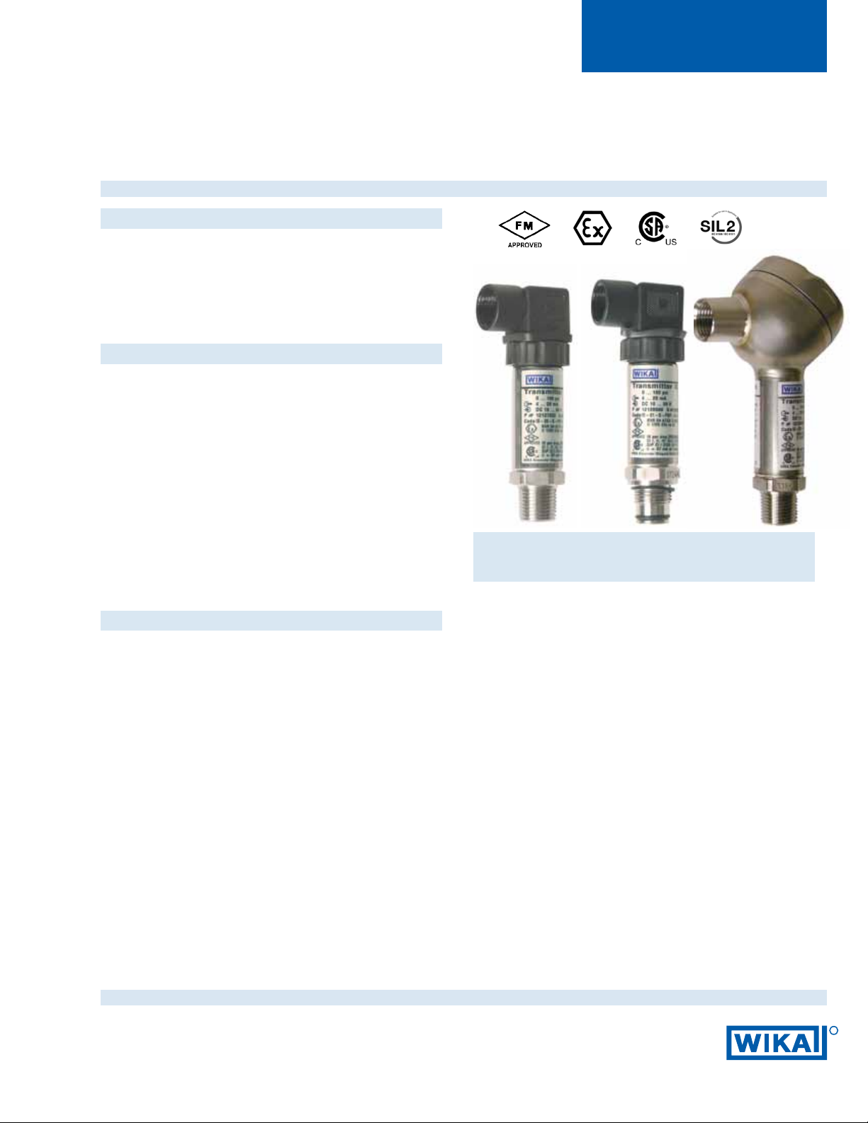
Intrinsically Safe Hazardous Area Transmitters
Type IS-20, IS-21, IS-20-F, IS-21-F
Applications
■ Chemical, Petrochemical
■ Oil and gas rening
■ Food industry
■ Mechanical engineering
Special Features
■ Pressure ranges from 50 InWC to 15,000 psi
■ FM, CSA approval for
- Intrinsically safe Class I, II and III Division 1,
Group A, B, C, D, E, F, G
- Dust Class II and III Division 1, Group E, F, G
- Class I, Zone 0, AEx ia II C
■ Ex- protection EEx ia I/II C T6 according to ATEX for:
Gases, vapors and mist: Connection to Zone 0,
Zone 1 and Zone 2
Dust: Connection to Zone 20,
Zone 21 and Zone 22
Mining: Category M1 and M2
Suitable for SIL 2 according to IEC 61508 / IEC 61511
Left: IS-20-S standard version
Center: IS-21-S with ush diaphragm
Right: IS-20-F with integral junction box
Datasheet IS-20, IS-21
Description
Approvals meet international standards
The IS-20 series of intrinsically safe pressure transmitters
are designed for industrial pressure measurement
applications in hazardous areas where intrinsically safe ratings are required.
Multiple intrinsically safe approvals include FM, ATEX
and CSA. These multiple approvals provide for global
recognition and acceptance of the intrinsically safe ratings.
The transmitters are labeled with all three approvals to help
support international shipments of OEM equipment
designed with these transmitters.
Rugged construction
The stainless steel wetted parts feature an all-welded measuring cell for improved media compatibility. There are no
internal soft sealing materials that may react with the media
or deteriorate over time. The compact case is also made of
stainless steel and is available with environmental protection
ratings up to NEMA 6 ( IP 68).
Datasheet IS-20, IS-21 · 1/2011
The IS-21-S and IS-21-F transmitters feature a ush
diaphragm process connection. They are specically
designed for the measurement of viscous uids or media
containing solids that may clog a NPT process connection.
Types IS-20-F and IS-21-F feature an integral stainless steel
junction box with internal terminal block for use in extremely
harsh environments. A ½“ NPT female conduit connection is
standard on all models and a cable compression electrical connection is available as an option.
All types require a 10 to 30 volt supply provided by an
intrinsically safe power supply or through an approved
intrinsically safe zener diode barrier.
Page 1 of 8
R
Page 2

Specications Type IS-20-S, IS-21-S, IS-20-F, IS-21-F
Specications without type designation apply for all types.
Pressure range
Maximum pressure*
Burst pressure**
Pressure range
Maximum pressure*
Burst pressure**
{vacuum, gauge pressure, compound ranges, and absolute pressure references are available}
1)
Ranges only available with Type IS-20
2)
For Type IS-21 the burst pressure is limited to 21,000 psi unless the pressure seal is accomplished by using the sealing ring underneath the hex.
*Pressure applied up to the maximum rating will cause no permanent change in specications but may lead to zero and span shifts
**Exceeding the burst pressure may result in destruction of the transmitter and possible loss of media
Materials
Wetted parts
Models IS-20-S, IS-20-F
Models IS-21-S, IS-21-F
Case
Internal transmission uid
Power supply U
Signal output and 4 ... 20 mA, 2-wire
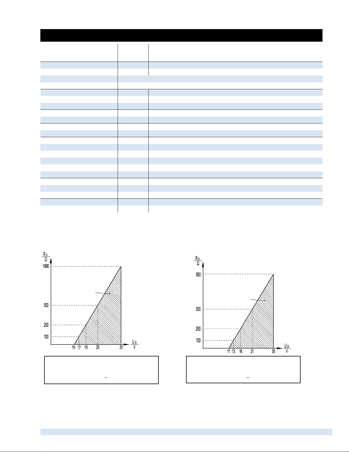
Maximum load R
Models IS-20-S
Models IS-20-F
Test circuit signal / max. load R
Adjustability zero/span % ± 5 using potentiometers inside the instrument
Response time (10 ... 90 %) ms < 1 (< 10 ms at media temperatures below –22°F (-30°C) for ranges < 300 psi
Power Pi W 1 (750 mW with approval for Category 1D)
Isolation voltage Isolation complies with EN 50020, 79-11
Accuracy
5)
Non-linearity % of span ≤ 0.2 (BFSL) according to IEC 61298-2
Non-repeatability % of span ≤ 0.1
1-year stability % of span ≤ 0.2 (at reference conditions)
Permissible temperature
Medium
Ambient
Storage
7) 8)
7) 8)
8)
Compensated temperature range 32 ... +176°F 0 ... +80°C
Temperature coecients (TC) within
compensated temperature range:
Mean TC of zero % of span
Mean TC of range % of span ≤ 0.2 / 10 K
CE-conformity
Pressure equipment directive 97/23/EC
EMC directive
50 InWC 5 psi 10 psi 25 psi 30 psi 60 psi 100 psi 160 psi 200 psi
15 psi 29 psi 58 psi 145 psi 145 psi 240 psi 500 psi 1,160 psi 1,160 psi
29 psi 35 psi 69 psi 170 psi 170 psi 290 psi 600 psi 1,390 psi 1,390 psi
300 psi 500 psi 1,000 psi 2,000 psi 3,000 psi 5,000 psi 8,000 psi 10,000 psi
1,160 psi 1,160 psi 1,740 psi 4,600 psi 7,200 psi 11,600 psi 17,400 psi 17,400 psi 21,750 psi
1,390 psi 5,800 psi 7,970 psi 14,500 psi 17,400 psi 24,650 psi
2
34,800 psi234,800 psi 43,500 psi
(for other materials see WIKA diaphragm seal program)
Stainless steel
Stainless steel {Hastelloy
®
C4}
O-ring: NBR {Viton® or EPDM}
3)
3)
Not available with Type IS-20 in pressure ranges > 300 psi
4)
Media temperature for oxygen version: -4 ... +140 °CF (-20 ... +60 °C). Not available in vacuum
or absolute pressure ranges or in Type IS-21 ush diaphragm version > 500 psi
B
A
DC V 10 < U ≤B 30 (11 < UB < 30 with Type IS-20 -F)
A
% of span ≤ 0.25 {0.125}
% of span ≤ 0.5 {0.25}
5)
Including non-linearity, hysteresis and repeatability.
Limit point Calibration performed in vertical mounting position with pressure connection facing down.
6)
For pressure ranges above 100 InWC
-20 ... +80 °C
-20 ... +80 °C
7)
Other temperature ranges are possible, depending on the electrical connection; see EC-type
8)
Also complies with EN 50178, Tab. 7, Type C, Class 4KH Operation, 1K4 Storage, 1K3 Transport
9)
Response time for IS-20: < 10 ms at medium temp. below -30 °C (-22 °F) for pressure ranges up to 300 psi
Response time for IS-21: < 10 ms at medium temp. below -30 °C (-22 °F) for all pressure ranges
Stainless steel
Synthetic oil {Halocarbon® oil for oxygen applications} 4) {Listed by FDA for food
applications}
≤ (UB – 10 V) / 0.02 A – (length of cable in feet x 0.043 Ohm)
R
A
≤ (UB – 11 V) / 0.02 A
R
A
in Ohms and UB in Volts
with R
A
RA < 15 Ohm (only for Type IS-20 -F)
6)
(BFSL)
6)
(limit point calibration)
7)
{extended temperature ranges see page 6}
7)
7)
-4 ... +176 °F
-4 ... +176 °F
7)
7)
-30 ... +105 °C -22 ... +221 °F
≤ 0.2 / 10 K
(< 0.4 for pressure range < 100 InWC)
2004/108/EC, EN 61 326 Emission (Group 1, Class B) and
Immunity (industrial locations)
1
15,000 psi
1
Page 2 of 8 Datasheet IS-20, IS-21 · 1/2011
Page 3
Specications Type IS-20-S, IS-21-S, IS-20-F, IS-21-F
■
Directive ATEX of equipment
intended for use in potentially 94/9/EC
explosive atmospheres
Ex-protection ATEX Category
Ignition protection type Ex ia I/II C T4, Ex ia I/II C T5, Ex ia I/II C T6
Ex-protection FM, CSA Class I, II and III
Ignition protection type Intrinsic safe Class I, II, III Division 1,
HF-immunity V/m 10
Burst kV 2
Functional safety Suitable for SIL 2 applications according to IEC 61508/ IEC 61511
Shock resistance
» Type IS-2X-S g 1,000 according to IEC 60068-2-27 (mechanical shock)
» Type IS-2X-F g 600 according to IEC 60068-2-27 (mechanical shock)
Vibration resistance
» Type IS-2X-S g 20 according to IEC 60068-2-6 (vibration under resonance)
» Type IS-2X-F g 10 according to IEC 60068-2-6 (vibration under resonance)
Wiring protection
■
Short-circuit Sig+ towards UB-
■
Reverse polarity UB+ towards UB-
Weight Type IS-2X-S
Type IS-2X-F
*) In an oxygen version type IS-21 is not available. In an oxygen version type IS-20 is only available in gauge pressure ranges ≥ 0.25 bar with media temperatures between
-20 … +60 °C / -4 … +140 °F and using stainless steel or Elgiloy® wetted parts.
{ } Items in curved brackets are optional extras for additional price.
8)
Read the operating conditions and safety-relevant data in the EC-type examination
certicate in any case (BVS 04 ATEX E 068 X)
Group A, B, C, D, E, F, G and Class I, Zone 0 AEx ia II C
Further information: "Additional Instructions Safety-related data IS-2X SIL"
lb Approx. 0.45
lb Approx. 0.80
8)
1G, 1/2G, 2G, 1D, 1/2D, 2D, M1, M2
Output signal and permissible load
Type IS-2X-S
4 ... 20 mA, 2-wire
Type IS-2X-F
4 ... 20 mA, 2-wire
permissible range
permissible range
Supply
Voltage
Output current (2-wire) Output current (2-wire)
4 ... 20 mA: RA < (UB – 10 V) / 0.02 A 4 ... 20 mA: RA < (UB – 11 V) / 0.02 A
Datasheet IS-20, IS-21 · 1/2011 Page 3 of 8
Page 4

Dimensions in inches (mm)
IS-2X-S (electrical connections)
Ingress Protection IP per IEC 60 529
L-connector plug
DIN EN 175301-803,
Form A
½ NPT conduit
IP 65
Order code: AX
ATEX: 1/2 G, M1
Circular connector,
M 12x1, 4-pin
IP 67
Order code: M4
ATEX: 1/2 G, M1
Cable with free ends
outer conductor
diameter 6.8 mm, PUR
NEMA 4 / IP 67
Order code: DL
ATEX: 1/2 G, M1
Bayonet connector
6-pin NEMA 4 / IP 67
Order code: C6
ATEX: 1/2 G
(not available with mining approval)
1.77“ (45mm)
1.14“ (29mm)
1.69“ (43mm)
Case
Pressure connections IS-20-S and IS-20-F
1/ 2 NPT male
Order code: ND
1/4 NPT male
Order code: NB
)
*
2.56“ (65mm)
1.36“ (34.5mm)
1.06“
(27mm)
G 1/2 metric
EN 837
Order code: GD
.71” 18mm)
1.73” 44mm)
G 1/4 metric
EN 837
Order code: GB
)
*
.75”
(19mm)
1.08”(27.5mm)
1/2NPT
.51”(13mm)
.85”(21.5mm)
1.12”(28.5mm)
.79”(20mm)
.12”(3mm)
.12”(3mm)
.24”
O
(6mm)
O
.69”
(17.5mm)
.85”(21.5mm)
Datasheet IS-20, IS-21 · 1/2011Page 4 of 8
.08”(2mm)
.51”(13mm)
.08”(2mm)
O
.20”
(5mm)
O
.37”
(9.5mm)
Page 5
Electrical connections
IS-2X-S
Cable with free ends,
zero/span not
adjustable,
conductor outer
diameter 6.8 mm, PUR
IP 68/NEMA 6
Order code: EM
ATEX: 1/2 G, M1
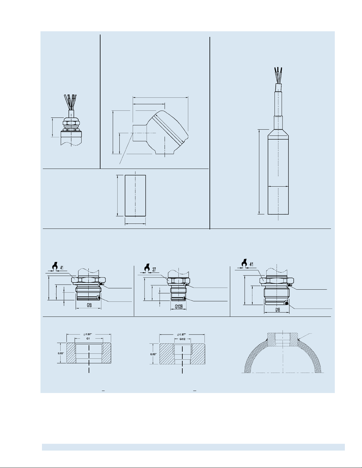
Electrical connections IS-2X-F
Integral junction box with internal spring
clip terminals NEMA 4X IP 67
Order code:
FE (1/2“ NPT female conduit standard)
FH (threaded connection brass nickel-plated)
FC (threaded connection stainless steel)
ATEX: 1/2 G, M1
3.35”(85mm)
1.89”(48mm)
2.41”(61mm)
Electrical connections IS-2X
-S
Cable with free ends,
zero/span not adjustable,
conductor outer diameter 7.5 mm, PUR {FEP}
NEMA 6P / IP 68
Order code: DM
ATEX: 1G, 1D, M1
1.00”(25.5mm)
Other connections
available
2.60”(66mm)
1.24”(31.5mm)
1/2” NPT female conduit
Case dimensions
2.13”(54mm)
1.06”(27mm)
IS-21-S and IS-21-F ush diaphragm pressure connections
G 1
50 InWC to 25 psi
Order code: 85
1.26”(31.9mm)
.81”(20.5mm)
.39”(10mm)
Sealing ring
29.7x35.7x2.0
O-ring 26x2
G 1/2
30 psi to 8,000 psi
Order code: 86
1.22”(31mm)
.81”(20.5mm)
.39”(10mm)
Sealing ring
18.5x23.9x1.5
O-ring 15x2
4.41”(112mm)
G 1
according to EHEDG **)
100 InWC to 250 psi
Order code: 83
1.52”(38.5mm)
.98”(25mm)
1.06”(27mm)
Sealing ring
29.7x35.7x2.0
O-ring 21.82x3.53
Matching P-1 weld insert adapters for IS-21-S and IS-21-F transmitters
P-1 G1 weld insert adapter
Part # 1206974
for pressure ranges < 25 psi
**) European Hygienic Equipment Design Group
{ } Items in curved brackets are optional extras at additional cost.
P-1 G1/2 weld insert adapter
Part # 1097008
for pressure ranges > 30 psi
weld
Cross section view of P-1
adapter installed in pipe.
Page 5 of 8Datasheet IS-20, IS-21 · 1/2011
Page 6
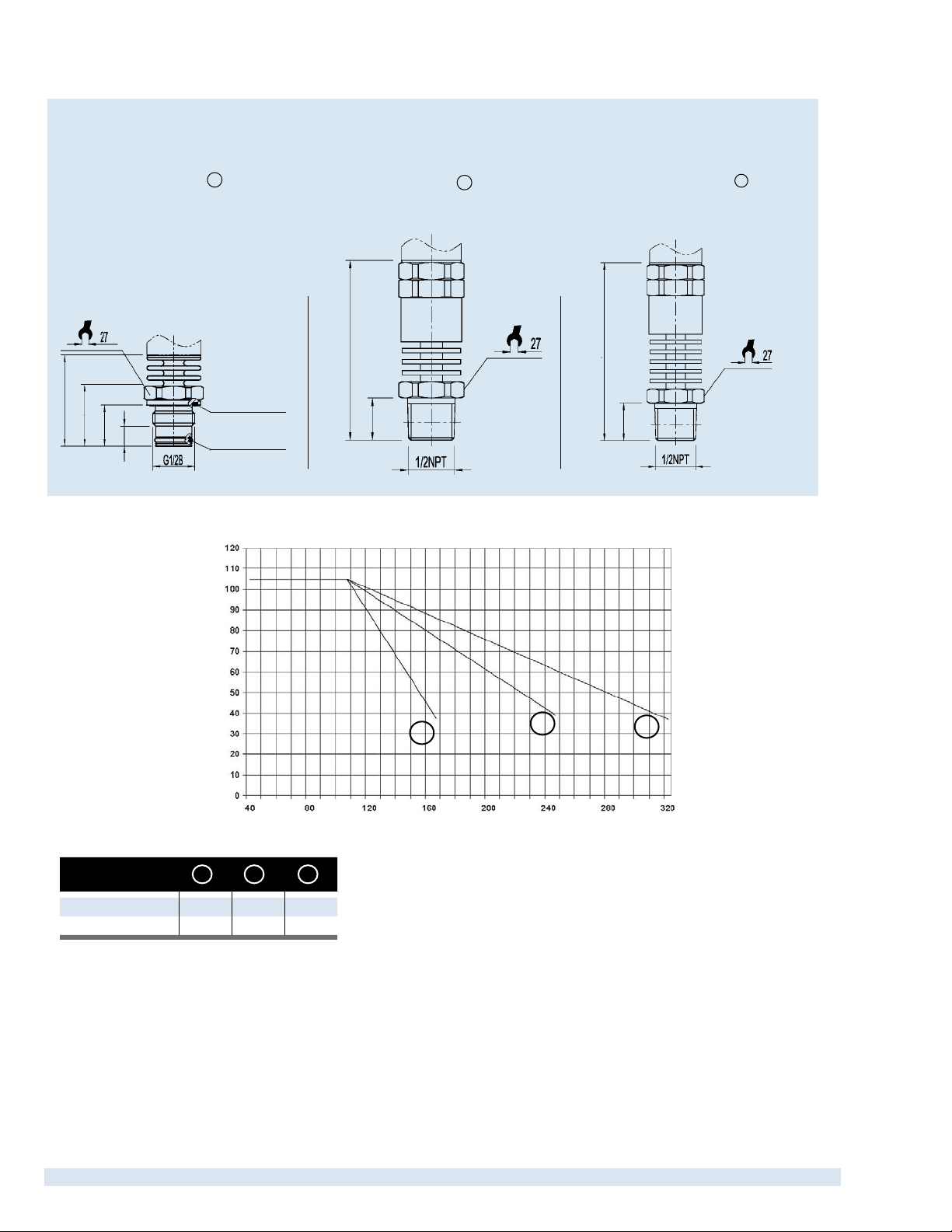
Pressure connections for high temperature media
IS-21-S and IS-21-F, ush diaphragm
-4 °F to 302 °F (-20 °C to 150 °C)
G 1/2
with 2 cooling ns (version A )
0 ... 30 psi up to 0 ... 8000 psi
Order code: 86 and C
sealing ring 18,5x23,9x1,5
1.79”(45.5mm)
1.22”(30.9mm)
.81”(20.5mm)
.39”(10mm)
O-ring 15.0x2,0
Relationship of media temperature to ambient temperature
IS-20-S and IS-20-F
-40 °F to 302 °F (-40 °C to 150 °C)
1/2 NPT male
with 3 cooling ns (version B )
0 - 5 psi to 0-15,000 psi
Order code: ND and 8
3.27”(83mm)
.75”(19mm)
IS-20-S and IS-20-F
-40 °F to 392 °F (-40 °C to 200 °C)
1/2 NPT male
with 5 cooling ns (version C )
0-5 psi to 0-15,000 psi
Order code: ND and 9
3.66”(93mm)
.75”(19mm)
Ambient Temperature in °C
Media Temperature in °C
Version
Cooling ns 2 3 5
K * 0.47 0.68 0.76
*cooling constant specic to each version
Calculation of cooling element performance:
TB = T
TB = Operating temperature of transmitter
T
T
K = Constant of cooling element
- (T
med
med
= maximum temperature of process media
med
= maximum ambient temperature
amb
A C
- T
) x K
amb
B
A
B
C
Maximum permissible ambient temperature:
T
= T
amb
+ (TB - T
med
med
) / K
Datasheet IS-20, IS-21 · 1/2011Page 6 of 8
Page 7

Permissible temperature ranges depending on electrical connections
Electrical connections
DIN 175301-803 A L-Connector
M 12x1 Circular connector M4 1/2 G (IIC)
Cable DL 1/2 G (IIC)
Bayonet connector
(not with mining)
Cable
zero/span not adjustable
Fieldcase
PUR Cable
zero/span not adjustable
FEP Cable
zero/span not adjustable
Ordercode
A4 1/2 G (IIC)
C6 1/2 G (IIC)
EM 1/2 G (IIC)
FE, FH, FC 1/2 G (IIC)
DM 1 G (IIA), 1/2 G (IIC)
DM 1 G (IIA), 1/2 G (IIC)
Category
M1 -40 ... +221 °F -40 ... +105 °C
M1 -13 ... +194 °F -25 ... +90 °C
M1 -4 ... +140 °F -20 ... +60 °C
M1 -4 ... +176 °F -20 ... +80 °C
M1 -58 ... +221 °F (T4) -50 ... +105 °C (T4)
1D, M1 14 ... +140 °F -10 ... +60 °C
1D -22 ... +140 °F -30 ... +60 °C
M1 -22 ... +221 °F -30 ... +105 °C
Ambient/Medium temperature range
-40 ... +140 °F (T6)
-40 ... +176 °F (T5)
-40 ... +221 °F (T4)
-13 ... +140 °F (T6)
-13 ... +176 °F (T5)
-13 ... +194 °F (T4)
-4 ... +140 °F (T6)
-4 ... +176 °F (T5)
-4 ... +176 °F (T4)
-58 ... +140 °F (T6)
-58 ... +176 °F (T5)
-58 ... +221 °F (T4)
-4 ... +140 °F (T6)
-4 ... +176 °F (T5)
-4 ... +176 °F (T4)
-58 ... +140 °F (T6)
-58 ... +176 °F (T5)
-58 ... +221 °F (T4
14 ... +140 °F (T6)
14 ... +140 °F (T5)
14 ... +140 °F (T4)
-22 ... +140 °F (T6)
-22 ... +176 °F (T5)
-22 ... +221 °F (T4)
-40 ... +60 °C (T6)
-40 ... +80 °C (T5)
-40 ... +105 °C (T4)
-25 ... +60 °C (T6)
-25 ... +80 °C (T5)
-25 ... +90 °C (T4)
-20 ... +60 °C (T6)
-20 ... +80 °C (T5)
-20 ... +80 °C (T4)
-50 ... +60 °C (T6)
-50 ... +80 °C (T5)
-50 ... +105 °C (T4)
-20 ... +60 °C (T6)
-20 ... +80 °C (T5)
-20 ... +80 °C (T4)
-50 ... +60 °C (T6)
-50 ... +80 °C (T5)
-50 ... +105 °C (T4
-10 ... +60 °C (T6)
-10 ... +60 °C (T5)
-10 ... +60 °C (T4)
-30 ... +60 °C (T6)
-30 ... +80 °C (T5)
-30 ... +105 °C (T4)
Wiring details
L-connector
DIN 175301-803 A
2-wire U+ = 1 U- = 2 U+ = 1 U- = 3 U+ = brown U- = green
Cable screen
Wire gauge up to max.1.5 mm
Cable diameter
Ingress protection
according to IEC 60 529
2-wire U+ = A U- = B U+ = 1 U- = 2 Test+ = 3 Test- = 4 screen = 5
Cable diameter 7-13 mm
Ingress protection
according to IEC 60 529
6-8 mm
ship approval: 10-14 mm
IP 65 IP 67
The ingress protection classes specied only apply while the pressure transmitter is connected with female
connectors that provide the corresponding ingress protection.
Bayonet connector, 6 pin Field case (with internal spring clip terminals)
IP 67 IP 67
The ingress protection classes specied only apply while the pressure transmitter is connected with female
connectors that provide the corresponding ingress protection.
2
Circular connector
M12x1, 4 pin
- 0.5 mm2 (AWG 20)
-
Cable,
1.5 m
PUR-cable: grey
FEP-cable: twisted and tinned
6.8 mm (Order code: DL / EM)
7.5 mm (Order code DM)
IP 67 - Order code: DL
IP 68 zero/span not adjustable - Order code: EM / DM
Page 7 of 8Datasheet IS-20, IS-21 · 1/2011
Page 8

Hazardous areas (ATEX zone classications)
Group II: Electrical equipment for use in all areas (except mines) which are endangered by
an explosive atmosphere.
Zone Category Occurrence of explosive atmosphere
Zone 0 Category 1G (gas)
Mounting to zone 0 Category 1/2 G
Zone 20 Category 1D (dust)
Mounting to zone 20 Category 1/2 D
Zone 1 Category 2G
Zone 21 Category 2D
Zone 2 Category 3G
Zone 22 Category 3D
Continuous
Intermittent
Hazard under abnormal conditions
Group I: Electrical equipment for use in mines (hazard due to mine gas)
Zone Category Requirements
Category M 1 Very high degree of safety
Category M 2
High degree of safety
(instruments have to be turned o if they are exposed to an explosive atmosphere)
Hazardous areas (ATEX in comparison with FM, CSA)
ATEX FM / CSA
Group Class Group
Gases and Vapors IIA / IIB / IIC I
Above ground
Mining Gas / Dusts I ID / IIF
ATEX Zone 0 (Zone 20 Dust) Zone 1 (Zone 21 Dust) Zone 2 (Zone 22 Dust)
FM /CSA Zone 0 Zone 1 Zone 2
FM (NEC505) Zone 0 Zone 1 Zone 2
The specications given in this document represent the state of engineering at the time of publishing.
e reserve the right to make modications to the specications and materials.
W
Flammable material
present continuously
Dusts II
Fibers III
Flammable material
present intermittently
Division 1 Division 2
A / B / C / D / E / F / G
Flammable material
normally not present
Page 8 of 8
Specications and dimensions given in this data sheet represent the state of engineering at the time of printing.
Modications may take place and materials specied may be replaced by others without prior notice.
Datasheet IS-20, IS-21 · 1/2011
R
WIKA Instrument Corporation
1000 Wiegand Boulevard
Lawrenceville, GA 30043
1-888-WIKA-USA /770-513-8200 (in GA)
Fax 770-338-5118
info@wika.com www.wika.com
 Loading...