

Page 1

2187800.09 GB/D/F/E 04/2008
WIKA Alexander Wiegand GmbH & Co. KG
Alexander-Wiegand-Straße 30
63911 Klingenberg/Germany
Phone (+49) 93 72/132-295
Fax (+49) 93 72/132-706
E-Mail support-tronic@wika.de
www.wika.de
Operating instructions
Betriebsanleitung
Mode d’emploi
Manual de instrucciones
IS-10,
IS-11
Pressure transmitter /
Druckmessumformer /
Transmetteur de pression /
Transmisor de presión
IS-10
Current terms and conditions apply.
Details are available on ...
Es gelten unsere aktuellen Verkaufsund Lieferbedingungen siehe unter ...
Toute commande est assujettie à nos
conditions de ventes et de fournitures
dans leur dernière version en vigueur, voir
sous ...
Se aplican nuestras condiciones actuales
de venta y de suministro, que se pueden
consultar en ...
www.wika.de
IS-11
Page 2

2187800.09 GB/D/F/E 04/2008
2
WIKA Operating instructions/Betriebsanleitung/Mode d'emploi/Instrucciones de servicio IS-10, IS-11
2187800.09 GB/D/F/E 04/2008
3
WIKA Operating instructions/Betriebsanleitung/Mode d'emploi/Instrucciones de servicio IS-10, IS-11
Contents Page 3-18 GB
1. Important details for your information
2. A quick overview for you
3. Signs, symbols and abbreviations
4. Function
5. For your safety
6. Packaging
7. Starting, operation
8. Adjustment of zero point / span
9. Maintenance, accessories
10. Trouble shooting
11. Storage, disposal
12. EC declaration of conformity
Inhalt Seite 19-34 D
1. Wichtiges zu Ihrer Information
2. Der schnelle Überblick für Sie
3. Zeichenerklärungen, Abkürzungen
4. Funktion
5. Zu Ihrer Sicherheit
6. Verpackung
7.
Inbetriebnahme, Betrieb
8. Einstellung Nullpunkt / Spanne
9. Wartung, Zubehör
10. Störbeseitigung
11. Lagerung, Entsorgung
12. EG-Konformitätserklärung
Contenu Page 35-50 F
1. Informations inportantes
2. Aperçu rapide
3. Explication des symboles,abréviations
4. Fonction
5. Pour votre sécurité
6. Emballage
7.
Mise en service, exploitation
8. Réglage du zéro / gain
9. Entretien, accessoires
10. Elimination de perturbations
11. Stockage, mise au rebut
12. Déclaration de confeamité CE
Contenido Paginás 51-66 E
1. Detalles importantes para su información
2. Resumen rápido para usted
3. Signos, símbolos y abreviaciones
4. Función
5. Para su seguridad
6. Embalaje
7.
Puesta en servicio, funcionamiento
8. Ajuste de cero / margen
9. Mantenimient o, accesorios
10. Eliminación de perturbaciones
11. Almacenaje, eliminación de desechos
12. Declaración de conformidad CE
Contents / Inhalt / Contenu / Contenido
E
F
1. Important details for your information
GB
Use of the product in accordance with the intended use IS-10 / IS-11:
Use the intrinsically safe pressure transmitter to transform the pressure into an electrical
signal in hazardous areas.
1. Important details for your information
Read these operating instructions before installing and starting the pressure transmitter. Keep
the operating instructions in a place that is accessible to all users at any time.
The following installation and operating instructions have been compiled by us with great care
but it is not feasible to take all possible applications into consideration. These installation and
operation instructions should meet the needs of most pressure measurement applications. If
questions remain regarding a specific application, you can obtain further information:
Via our Internet address www.wika.de / www.wika.com
The product data sheet is designated as PE 81.22
Contact WIKA for additional technical support (+49) 9372 / 132-295
If the serial number gets illegible (e.g. by mechanical damage or repainting), the retraceability
of the instrument is not possible any more.
WIKA pressure transmitters are carefully designed and manufactured using state-of-the-art
technology. Every component undergoes strict quality and environmental inspection before
assembly and each instrument is fully tested prior to shipment. Our environmental management system is certified to DIN EN ISO 14001.
GB D
Certificate ATEX: Pressure transmitter for operation in hazardous areas in compliance with
the respective certificate (see attached EC-type test certificate DMT 00 ATEX E 045X).
ATEX Approval ratings: Gases and mist installation in Zone 1, Zone 2. Mounting to Zone 0.
Mining Category M1, M2.
Knowledge required
Install and start the pressure transmitter only if you are familiar with the relevant regulations
and directives of your country and if you have the qualification required. You have to be
acquainted with the rules and regulations on hazardous areas, measurement and control
technology and electric circuits, since this pressure transmitter is „electrical equipment“ as
defined by EN 50178. Depending on the operating conditions of your application you have to
have the corresponding knowledge, e.g. of aggressive media.
Page 3

2187800.09 GB/D/F/E 04/2008
4
WIKA Operating instructions/Betriebsanleitung/Mode d'emploi/Instrucciones de servicio IS-10, IS-11
2187800.09 GB/D/F/E 04/2008
5
WIKA Operating instructions/Betriebsanleitung/Mode d'emploi/Instrucciones de servicio IS-10, IS-11
3. Signs, symbols and abbreviations
4. Function
IS-10: Pressure connection (intrinsically safe) with internal diaphragm (standard version).
IS-11: Pressure connection with flush diaphragm (intrinsically safe) for highly viscous or
solids entrained media which might clog the pressure port.
2-wire Two connection lines are intended for the voltage supply.
The supply current is the measurement signal.
FDA Food and Drug Administration
Function: The pressure prevailing within the application is transformed into a standardised
electrical signal through the deflection of the diaphragm, which acts on the sensor element
with the power supply fed to the transmitter. This electric signal changes in proportion to the
pressure and can be evaluated correspondingly.
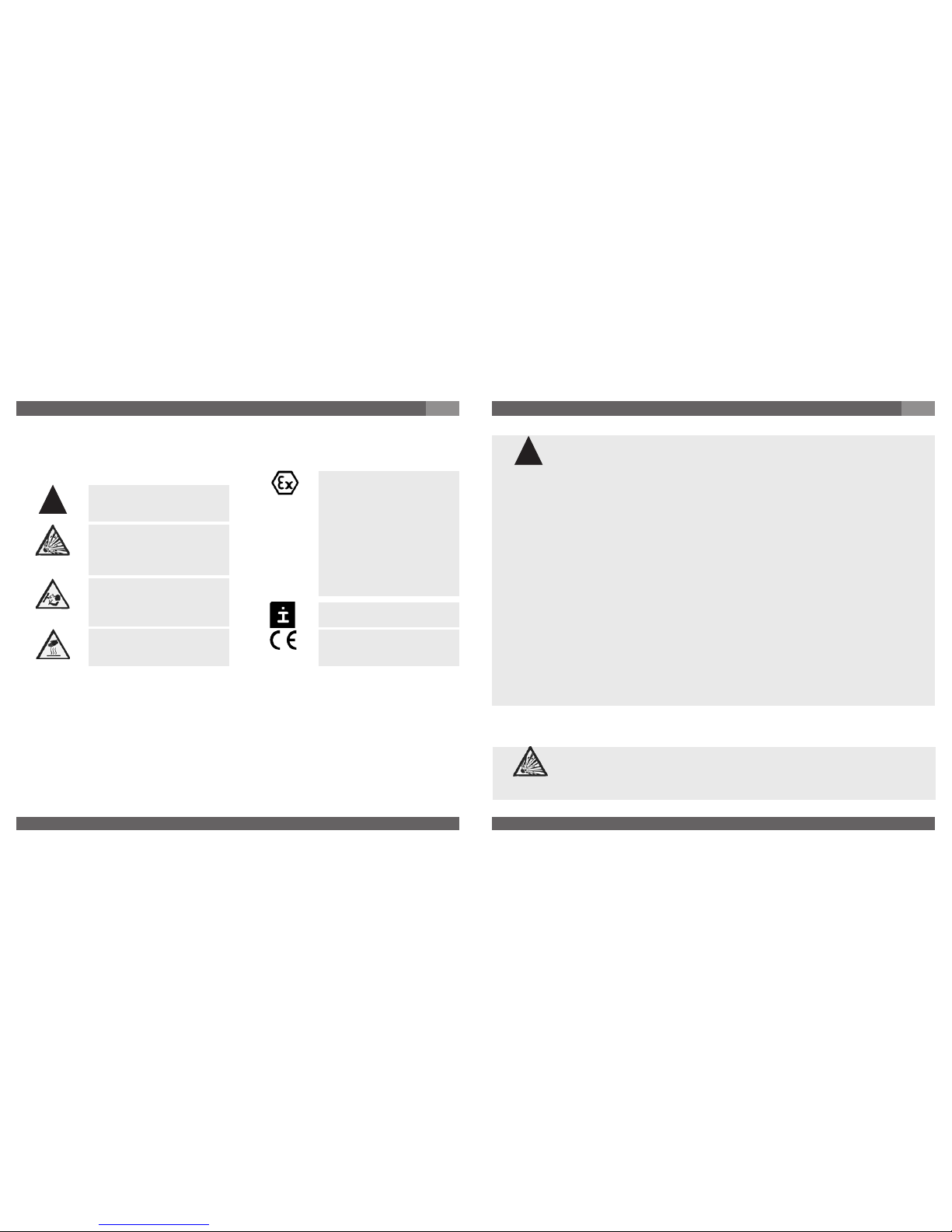
Potential danger of life or of
severe injuries.
Notice, important information, malfunction.
The product complies with
the applicable European
directives.
Instructions for hazardous
areas: Potential danger of
life or of severe injuries.
2. A quick overview for you / 3. Abbreviations, signs / 4. Function
GB
2. A quick overview for you
If you want to get a quick overview, read Chapters 3, 5, 7 and 11. There you will get some
short safety instructions and important information on your product and its starting. Read
these chapters in any case.
Potential danger of life or
of severe injuries due to
catapulting parts.
Potential danger of burns
due to hot surfaces.
ATEX
European guideline for
explosion protection
(Atmosphäre=AT,
Explosion= EX)
The product complies with
the requirements of the
European directive 94/9/EC
(ATEX) on explosion protection.
5. For your safety
5. For your safety
GB
Select the appropriate pressure transmitter with regard to scale range,
performance and specific measurement conditions prior to installing and
starting the instrument.
Observe the relevant national regulations (e.g.: EN 50178) and observe the
applicable standards and directives for special applications (e.g. with
dangerous media such as acetylene, flammable gases or liquids and toxic gases or liquids
and with refrigeration plants or compressors). If you do not observe the appropriate
regulations, serious injuries and/or damage can occur!
Open pressure connections only after the system is without pressure!
Please make sure that the pressure transmitter is only used within the overload threshold
limit all the time!
Observe the ambient and working conditions outlined in section 7 „Technical data”.
Ensure that the pressure transmitter is only operated in accordance with the provisions i.e.
as described in the following instructions.
Do not interfere with or change the pressure transmitter in any other way than described in
these operating instructions.
Remove the pressure transmitter from service and mark it to prevent it from being used
again accidentally, if it becomes damaged or unsafe for operation
Take precautions with regard to remaining media in removed pressure transmitter.
Remaining media in the pressure port may be hazardous or toxic!
Have repairs performed by the manufacturer only.
Information about material consistency against corrosion and diffusion can be found in our
WIKA-Handbook, 'Pressure and Temperature Measurement'.
Consider the details given in the EC-type examination certificate as well
as the respective specifications for explosion hazard use of the country
concerned (e.g.: IEC 60079-14). If you do not observe these stipulations,
serious injuries and/or damage can occur.
!
Warning
Warning
Warning
Caution
!
Warning
Warning
Page 4
2187800.09 GB/D/F/E 04/2008
6
WIKA Operating instructions/Betriebsanleitung/Mode d'emploi/Instrucciones de servicio IS-10, IS-11
2187800.09 GB/D/F/E 04/2008
7
WIKA Operating instructions/Betriebsanleitung/Mode d'emploi/Instrucciones de servicio IS-10, IS-11
6. Packaging / 7. Starting, operation
GB
6. Packaging
Has everything been supplied?
Check the scope of supply:
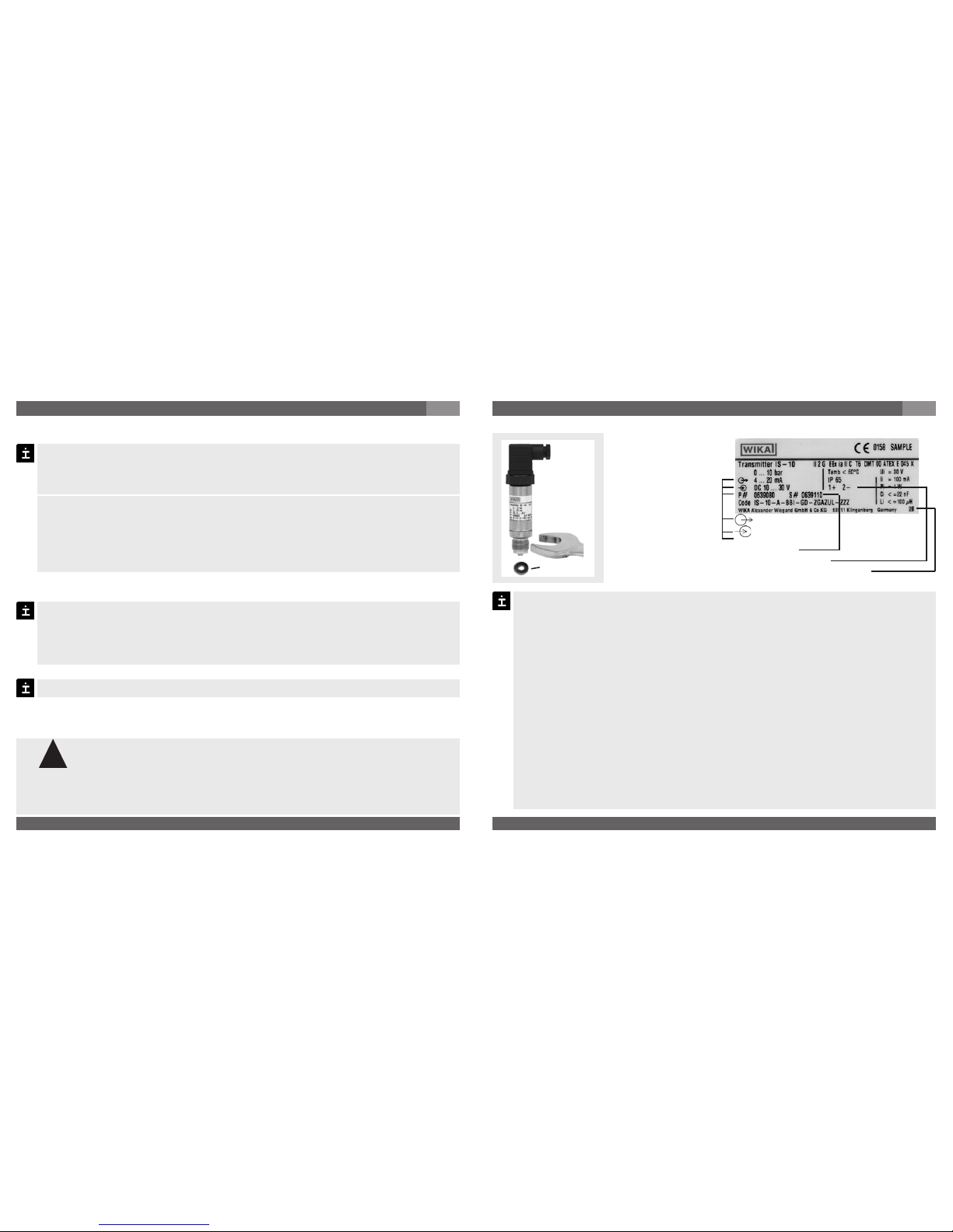
Completely assembled pressure transmitters; with flush version IS-11 including preassembled sealings and protection cap.
EC-type examination certificate
Inspect the pressure transmitter for possible damage during transportation. Should
there be any obvious damage, inform the transport company and WIKA without delay.
Keep the packaging, as it offers optimal protection during transportation (e.g. changing installation location, shipment for repair).
Ensure that the pressure connection thread and the connection contacts will not be
damaged.
In order to protect the diaphragm, the pressure connection of the instrument IS-11 is provided
with a special protection cap.
Remove this protection cap only just before installing the pressure transmitter in order
to prevent any damage to the diaphragm or the thread.
Keep the protection cap of the pressure connection thread and the diaphragm for
later storage or transport.
Mount the protection cap when removing and transporting the instrument.
7. Starting, operation
Diaphragm test for your safety
It is necessary that before starting the pressure transmitter you test the diaphragm visually, as
this is a safety-relevant component.
Pay attention to any liquid leaking out, for this points to a diaphragm
damage.
Check the diaphragm visually for any damage (IS-11).
Use the pressure transmitter only if the diaphragm is undamaged.
Use the pressure transmitter only if it is in a faultless condition as far as the
safety-relevant features are concerned.
Required tools: wrench (flats 27), screw driver
7. Starting, operation
GB
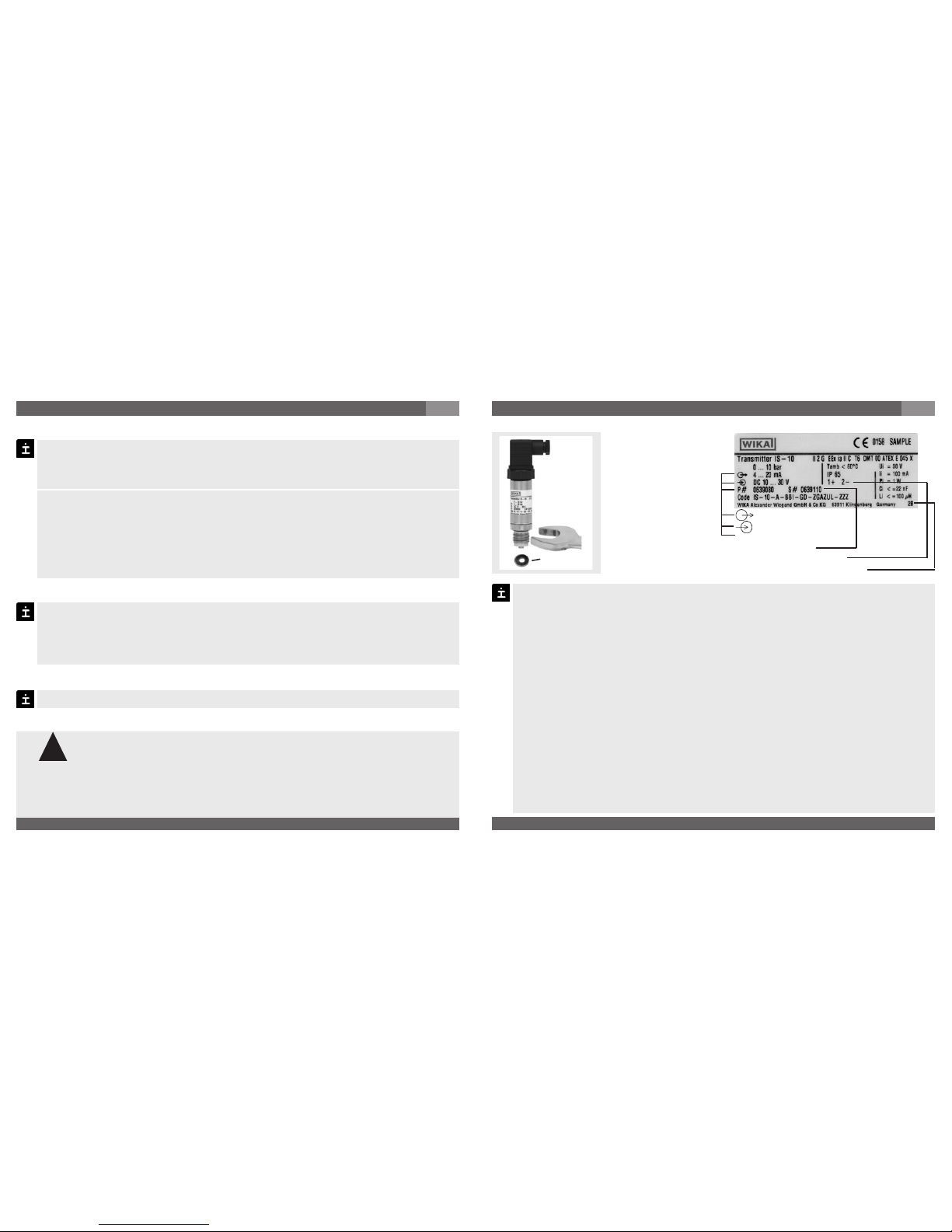
Signal
Power Supply
Product No.
Serial No.
PIN assignment
Coded manufacture date
P #
max.
50 Nm
Sealing
Mechanical connection Product label (example)
Remove the protection cap only just before installation and absolutely avoid any
damage to the diaphragm during installation as well (IS-11).
For Model IS-10 you have to provide for a sealing element; exceptions are instruments with self-sealing threads (e.g. NPT thread).
For Model IS-11 the sealing ring is included in delivery.
Please refer to our data sheet “Pressure gauge sealing washers AC 09.08” in WIKA’s
product catalog Pressure and Temperature Measurement or our website
www.wika.de for details about sealing washers.
When mounting the instrument, ensure that the sealing faces of the instrument and
the measuring point are clean and undamaged.
Screw in or unscrew the instrument only via the flats using a suitable tool and the
prescribed torque. The appropriate torque depends on the dimension of the pressure
connection and on the sealing element used (form/material). Do not use the case as
working surface for screwing in or unscrewing the instrument.
When screwing the transmitter in, ensure that the threads are not jammed.
For tapped holes and welding sockets please see Technical Information IN 00.14 for
download at www.wika.de -Service
S #
!
Warning
Page 5

2187800.09 GB/D/F/E 04/2008
8
WIKA Operating instructions/Betriebsanleitung/Mode d'emploi/Instrucciones de servicio IS-10, IS-11
2187800.09 GB/D/F/E 04/2008
9
WIKA Operating instructions/Betriebsanleitung/Mode d'emploi/Instrucciones de servicio IS-10, IS-11
7. Starting, operation
GB
Protect the diaphragm against any contact with abrasive substances and
pressure peaks and do not touch it with tools. If you damage the diaphragm,
no intrinsic safety can be guaranteed (ATEX)!
Observe the permissible surface temperature applicable for this range
according to the defined temperature classes.
Observe the technical data for the use of the pressure transmitter in connection with aggressive / corrosive media and for the avoidance of mechanical
hazards.
When mounting the pressure transmitter into areas which require category
1G equipment, ensure that ingress protection IP67 according to IEC 60 529
is guaranteed.
Mounting to zone 0
(In general Zone 0 is given when the pressure transmitter is surrounded by a mixture of explosive gases more than 1.000 hours per year = continuous hazard).
7. Starting, operation
GB
Operate the pressure transmitter with a shielded cable and earth the shield at least on
one side of the cable, if the cable is longer than 30m (2-wire), or if it is run outside of
the building.
Ingress protection per IEC 60529 (The ingress protection classes specified only apply
while the pressure transmitter is connected with female connectors that provide the
corresponding ingress protection).
Ensure that the cable diameter you select fits to the cable gland of the connector
Ensure that the cable gland of the mounted connector is positioned correctly and
that the sealings are available and undamaged. Tighten the threaded connection and
check the correct position of the sealings in order to ensure the ingress protection.
Please make sure that the ends of cables with flying leads do not allow any ingress of
moisture.
Electrical connection
Ground the cable screen at one end, preferably in the safe, thus nonEx, area (EN 60079-14). For transmitters with flying leads, the screen is
connected to the case. The simultaneous connection of case and cable
screen to ground is only permitted if ground loop problems between the
screen connection (e.g. at the power supply) and case can be excluded (see
EN 60079-14).
Supply the pressure transmitter from an intrinsically safe current circuit (Ex ia).
Consider both the internal capacitance and inductance.
Always connect the case to earth to protect the pressure transmitter against
electromagnetic fields and electrostatic charges.
Cover flying leads with fine wires by an end splice (cable preparation).
The bayonet-connector is made of light metal, a material which is not
permissible for group I applications (mining).
Consider that cables for use in zones 1 and 2 must be checked with a test
voltage between conductor/earth, conductor/screen, screen/earth of more
than 500V (AC).
Warning
Warning
Warning
!
Warning
Warning
Page 6
2187800.09 GB/D/F/E 04/2008
10
WIKA Operating instructions/Betriebsanleitung/Mode d'emploi/Instrucciones de servicio IS-10, IS-11
2187800.09 GB/D/F/E 04/2008
11
WIKA Operating instructions/Betriebsanleitung/Mode d'emploi/Instrucciones de servicio IS-10, IS-11
7. Starting, operation
GB
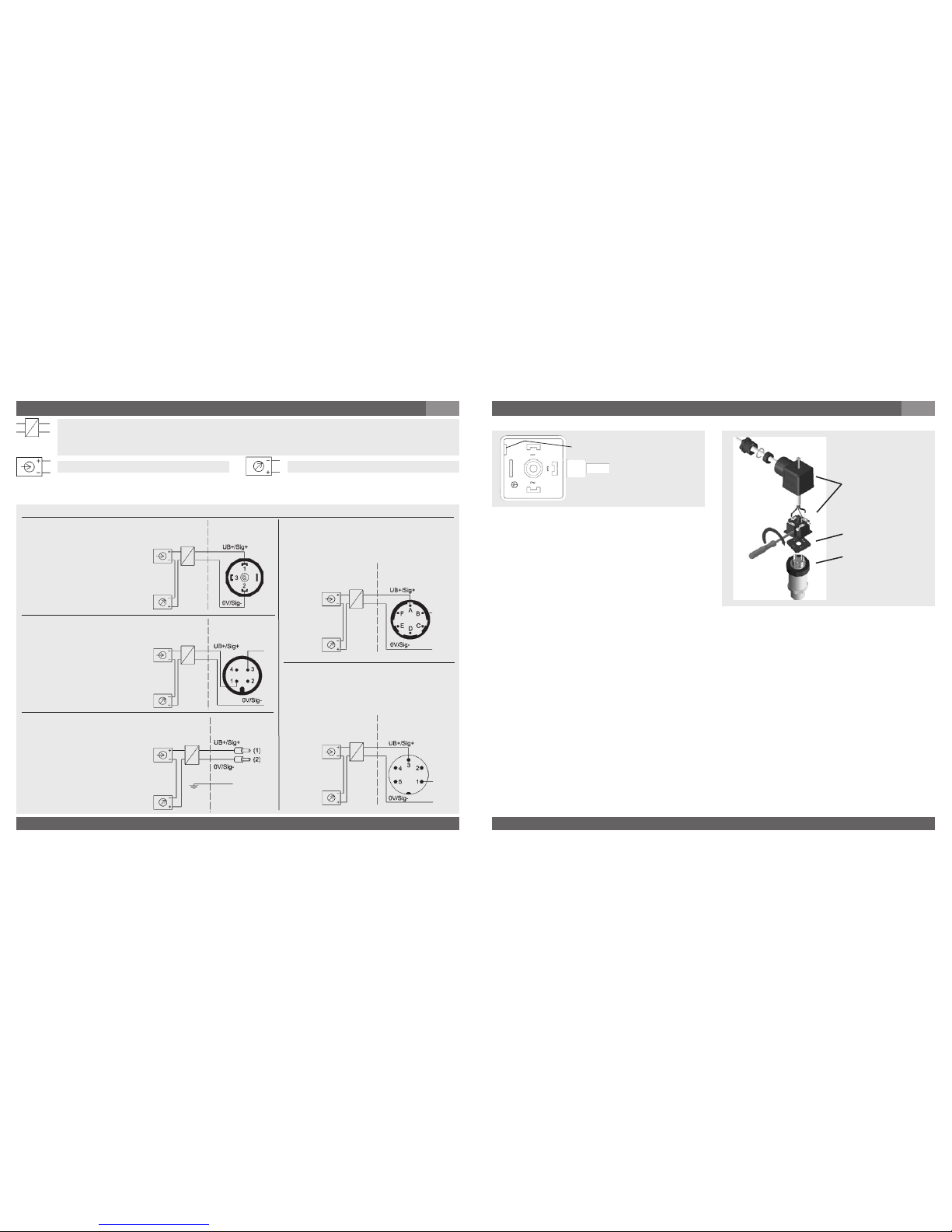
Load (e.g. display)
Power supply
UB+/Sig+ Positive supply / measurement connection
OV/Sig- Negative supply / measurement connection
Circular connector
M 12x1,
IP 67
Order code: M4
Flying leads
with 1.5 m of cable,
conducter cross section
up to max. 0.5 mm²,
AWG 20 with end splices,
conducter outer diameter
6.8 mm
IP 67
Order code: DL
L-Connector,
DIN EN 175301-803,
Form A
for conducter cross section
up to max. 1.5 mm²,
conducter outer diameter
6 to 8 mm
IP 65
Order code: A4
2-wire
brown
green
With a line transformer you realise the mandatory galvanic isolation of the voltage
and current supply between hazardous and non-hazardous areas and ensure the
safety connection data.
Non hazardous
area
Hazardous
(classified) area
Non hazardous
area
Hazardous
(classified) area
Non hazardous
area
Hazardous
(classified) area
screen
Non hazardous
area
Hazardous
(classified) area
Non hazardous
area
Hazardous
(classified) area
Bayonet-connector,
IP 67
Order code: C6
Connector M16x0.75,
IP 65,
Order code: B5
(D) Mounting hole
1. Loosen the screw (1).
2. Loosen the cable gland (2).
3. Pull the angle housing (5), with the
terminal block (6) inside, away from the
instrument.
4. Using the head of a small screwdriver in
the mounting hole (D), lever the terminal
block (6) out of the angle housing (5).
In order not to damage the sealing of the angle housing, do not try to push the terminal
block (6) out using the screw hole (1) or the cable gland (2).
5. Ensure that the conductor outer diameter you select is matched to the angle housing’s
cable gland. Slide the cable through the cable gland nut (2), washer (3), gland seal (4) and
angle housing (5).
6. Connect the flying leads to the screw terminals on the terminal block (6) in accordance
with the pin-assignment drawing.
7. Press the terminal block (6) back into the angle housing (5).
8. Tighten the cable gland (2) around the cable. Make sure that the sealing isn’t damaged
and that the cable gland and seals are assembled correctly in order to ensure ingress
protection.
9. Place the flat, square gasket over the connection pins on the top of the instrument
housing.
10. Slide the terminal block (6) onto the connection pins.
11. Secure the angle housing (5) and terminal block (6) to the instrument with the screw (1).
Assembly of L-connector DIN EN 175301-803
(6)
(5)
(1)
(2)
(3)
(4)
Clamping nut,
Male connector,
Case with
pressure connection
Sealing
Female
connector
7. Starting, operation
GB
Page 7

2187800.09 GB/D/F/E 04/2008
12
WIKA Operating instructions/Betriebsanleitung/Mode d'emploi/Instrucciones de servicio IS-10, IS-11
2187800.09 GB/D/F/E 04/2008
13
WIKA Operating instructions/Betriebsanleitung/Mode d'emploi/Instrucciones de servicio IS-10, IS-11
Specifications Model IS-10 / IS-11
Pressure ranges
*)
bar 0.1 0.16 0.25 0.4 0.6 1 1.6 2.5 4 6 10 16
Over pressure safety bar 1 1.5 2 2 4 5 10 10 17 35 35 80
Burst pressure bar 2 2 2.4 2.4 4.8 6 12 12 20.5 42 42 96
Pressure ranges
*)
bar 25 40 60 100 160 250 400 600 1000
1)
Over pressure safety bar 50 80 120 200 320 500 800 1200 1500
Burst pressure bar 96 400 550 800 1000 1200 1700 2)2400 2)3000
{Vacuum, gauge pressure, compound range, absolute pressure are available}
1)
Only Model IS-10.
2)
For model IS-11: the value specified in the table applies only when sealing is
realised with the sealing ring underneath the hex. Otherwise max. 1500 bar applies.
Materials
Wetted parts (Other materials see WIKA diaphragm seal program)
Model IS-10
*)
» Stainless steel
Model IS-11» Stainless steel {Hastelloy}
O-ring: NBR {FPM/FKM or EPDM}
Case Stainless steel
Internal transmission fluid
3)
Synthetic oil {Halocarbon oil for oxygen applications}
{Listed by FDA for Food and Beverage}
3)
Not for IS-10 with pressure ranges > 25 bar.
Power supply UB UB in VDC
10 < UB ≤ 30
Signal output and 4 … 20 mA, 2-wire
maximum ohmic load RA RA in Ohm RA ≤ (UB – 10 V) / 0.02 A - (length of flying leads in m x 0.14 Ohm)
Adjustability zero/span % ± 10 using potentiometers inside the instrument
Response time (10 ... 90 %) ms
≤ 1
Dielectric strength Insulation complies with EN 50020, 6.4, 12
Specifications Model IS-10 / IS-11
Accuracy % of span
≤ 0.25 {0.125}
4)
(BFSL)
≤ 0.5 5) {0.25}
4) 5)
4)
Accuracy { } for pressure ranges ≥ 0.25 bar
5)
Including non-linearity, hysteresis, zero point and full scale error (corresponds to
error of measurement per IEC 61298-2).
Adjusted in vertical mounting position with lower pressure connection.
Non-linearity % of span
≤ 0.2 (BFSL) according to IEC 61298-2
Non-repeatability % of span
≤ 0.1
1-year stability % of span
≤ 0.2 (at reference conditions)
Permissible temperature of
Medium
6) 7) *)
-30 ... +105 °C -22 ... +221 °F
Ambience
6) 7)
-30 ... +105 °C -22 ... +221 °F
Storage
6)
-30 ... +105 °C -22 ... +221 °F
6)
Also complies with EN 50178, Tab. 7, Operation (C) 4K4H, Storage (D) 1K4,
Transport (E) 2K3
Compensated temp range 0 ... +80 °C 32 ... +176 °F
Temperature coefficients within
compensated temp range
Mean TC of zero % of span
≤ 0.2 / 10 K (< 0.4 for pressure range ≤ 250 mbar)
Mean TC of range % of span
≤ 0.2 / 10 K
CE- conformitiy
97/23/EC Pressure equipment directive
89/336/EEC emission (class B) and immunity according to EN 61 326
94/9/EC Directive ATEX of equipment intended for use in potentially
explosive atmospheres
Ex-protection ATEX Category
7)
1G, 1/2G, 2G, M1, M2
Ignition protection type EEx ia I/II C T4, EEx ia I/II C T5, EEx ia I/II C T6
7)
Read the operating conditions and safety-relevant data in the EC-type
examination certificate in any case (DMT 00 ATEX E 045 X)
7. Starting, operation
GB
7. Starting, operation
GB
Page 8

2187800.09 GB/D/F/E 04/2008
14
WIKA Operating instructions/Betriebsanleitung/Mode d'emploi/Instrucciones de servicio IS-10, IS-11
2187800.09 GB/D/F/E 04/2008
15
WIKA Operating instructions/Betriebsanleitung/Mode d'emploi/Instrucciones de servicio IS-10, IS-11
Specifications Model IS-10 / IS-11
RF-immunity V/m 10 {30}
BURST KV 4
Shock resistance g 1000 according to IEC 60068-2-27 (mechanical shock)
Vibration resistance g 20 according to IEC 60068-2-6 (vibration under resonance)
Wiring protection
Protected against reverse polarity and short circuiting on the instrument side
Weight kg Approx. 0.2
When designing your plant, take into account that the stated values (e.g.burst pressure,
over pressure safety) apply depending on the material, thread and sealing element used.
7. Starting, operation
GB
*) In an oxygen version model IS-11 is not available. In an oxygen version model IS-10 is only available in gauge pressure ranges
≥ 0.25 bar with media temperatures between -4 … +140 °F / -20 … +60 °C and using stainless steel or Elgiloy® wetted parts.
{ } Items in curved brackets are optional extras for additional price.
Functional test
Open pressure connections only after the system is without pressure!
Observe the ambient and working conditions outlined in section 7
„Technical data.
Please make sure that the pressure transmitter is only used within the over
load threshold limit at all times!
When touching the pressure transmitter, keep in mind that the surfaces of
the instrument components might get hot during operation.
The output signal must be proportional to the pressure. If not, this might point to a
damage of the diaphragm. In that case refer to chapter 10 „Troubleshooting“.
Z = Zero
S = Span
Female
connector
Sealing
Clamping
nut
Male
connector
Sealing
Case with
pressure
connection
Recommended recalibration cycle: 1 year
For further information (+49) 9372/132-295
8. Adjustment of zero point / span (only for pressure transmitter with
clamping nut)
A
B
We do not recommend to adjust the span potentiometer. It is used for adjustment ex
factory and should not be adjusted by you unless you have adequate calibration equipment at your disposal (at least three times more accurate than the instrument being
tested).
8. Adjustment of zero point / span
GB
Make sure wires are not cut or pinche
during disassembly and reassembly of
the connector.
Remove the female connector. Open
the pressure transmitter by detaching
the clamping nut (see Fig. A ). Carefully
remove the male connector from the
case.
Adjust the zero point (Z) (see Fig. B ) by
generating the lower limit of the pressure
range.
Adjust the span (S) by generating the
higher limit of the pressure range.
Check the zero point.
If the zero point is incorrect, repeat
procedure as required.
Reassemble the instrument carefully.
Make sure all sealings and o-rings are
not damaged and correctly installed to
assure the rated moisture ingress protection.
Warning
Caution
Page 9

2187800.09 GB/D/F/E 04/2008
16
WIKA Operating instructions/Betriebsanleitung/Mode d'emploi/Instrucciones de servicio IS-10, IS-11
2187800.09 GB/D/F/E 04/2008
17
WIKA Operating instructions/Betriebsanleitung/Mode d'emploi/Instrucciones de servicio IS-10, IS-11
Failure Possible cause Procedure
Output signal unchanged after change
in pressure
Mechanical overload through overpressure
Replace instrument; if failure reoccurs,
consult the manufacturer *)
No output signal Cable break Check connections and cable
Signal span too small
Mechanical overload through overpressure
Replace instrument; if failure reoccurs,
consult the manufacturer *)
Failure Possible cause Procedure
Signal span erratic / incorrect Working temperature too high/too low
Ensure permissible temperatures as per
the Operating Instructions
Signal span erratic Instrument not grounded Ground instrument
Violent fluctuations in the process
media pressure
Damping; consult with manufacturer
Electromagnetic interference source in
the vicinity, e.g. inverter drive
Shield the device; shield the cables;
remove the interference source
Signal span dropping off/too small
Diaphragm is damaged, e.g. through
impact, abrasive/agressive media;
corrosion of diaphragm/pressure
connector; transmission fluid missing.
Contact the manufacturer and replace
the instrument
Signal span drops off
Seal/Sealing face damaged/contaminated, seal mounted incorrectly,
threads crossed
Clean the seal/sealing face, possibly
replace the seal.
Abnormal zero point signal Working temperature too high/too low
Ensure permissible temperatures as per
the Operating Instructions
Abnormal mounting position
Correct the zero point through the
potentiometer, control panel or software
Overload limits exceeded
Ensure permissible overload limits are
observed (see Operating Instructions) *)
9. Maintenance, accessories / 10. Trouble shooting
GB
9. Maintenance, accessories
Accessories
For details about the accessories (e. g. connectors), please refer to WIKA‘s price list, WIKA‘s
product catalog on CD or or contact our sales department.
10. Trouble shooting
Open pressure connections only after the system is without pressure!
WIKA pressure transmitters require no maintenance.
Have repairs performed by the manufacturer only.
Do not insert any pointed or hard objects into the pressure port for cleaning to prevent
damage to the diaphragm of the pressure connection.
Take precautions with regard to remaining media in removed pressure transmitters. Remaining media in the pressure port may be hazardous or
toxic!
Remove the pressure transmitter from service and mark it to prevent it from
being used again accidentally, if it becomes damaged or unsafe for operation.
Have repairs performed by the manufacturer only.
10. Trouble shooting
GB
In case of unjustified reclamation we charge the reclamation handling expenses.
*) Make sure that after the setting the unit is working properly. In case the error continues to exist send in the instrument for reparation (or
replace the unit).
Please verify in advance if pressure is being applied (valves/ ball valve etc. open) and if the
right voltage supply and the right type of wiring (2-wire/ 3-wire) has been chosen?
If the problem persists, contact our sales department.
Process material certificate (Contamination declaration for returned goods)
Purge / clean dismounted instruments before returning them in order to protect our employees
and the environment from any hazard caused by adherent remaining media.
Service of instruments can only take place safely when a Product Return Form has been
submitted and fully filled-in. This Return Form contains information on all materials with which
the instrument has come into contact, either through installation, test purposes, or cleaning.
You can find the Product Return Form on our internet site (www.wika.de / www.wika.com).
Warning
!
Warning
Page 10
2187800.09 GB/D/F/E 04/2008
18
WIKA Operating instructions/Betriebsanleitung/Mode d'emploi/Instrucciones de servicio IS-10, IS-11
2187800.09 GB/D/F/E 04/2008
19
WIKA Operating instructions/Betriebsanleitung/Mode d'emploi/Instrucciones de servicio IS-10, IS-11
responsibility, that the
marked products
Nous déclarons sous notre
seule responsabilité que les
appareils marqués
transmitter
Transmetteur de pression,
version securite intrinseque
sheet:
selon fiche technique en
vigueur:
responsibility, that the
marked products
Nous déclarons sous notre
seule responsabilité que les
appareils marqués
transmitter
Transmetteur de pression,
version securite intrinseque
sheet:
selon fiche technique en
vigueur:
requirements of the Directives
sont conformes aux exigences
essentielles de la directive
- 94/9/EC (ATEX)
- 89/336/CEE (CEM)
- 94/9/CE (ATEX)
The devices have been tested
according to the norm:
Les appareils ont été vérifiés
suivant les normes:
WIKA Alexander Wiegand GmbH
& Co. KG
WIKA Alexander Wiegand GmbH &
Co. KG
responsibility, that the
marked products
Nous déclarons sous notre
seule responsabilité que les
appareils marqués
transmitter
Transmetteur de pression,
version securite intrinseque
sheet:
selon fiche technique en
vigueur:
requirements of the Directives
sont conformes aux exigences
essentielles de la directive
- 94/9/EC (ATEX)
- 89/336/CEE (CEM)
- 94/9/CE (ATEX)
The devices have been tested
according to the norm:
Les appareils ont été vérifiés
suivant les normes:
11. Storage, disposal / 12. EC declaration of conformity
GB
11. Storage, disposal
When storing or disposing of the pressure transmitter, take precautions with
regard to remaining media in removed pressure transmitters. We recommend cleaning the transmitter properly and carefully. Remaining media in
the pressure port may be hazardous or toxic!
Mount the protection cap when storing the pressure transmitter in order to prevent any
damage to the diaphragm (IS-11).
Dispose of instrument components and packaging materials in accordance with the
respective waste treatment and disposal regulations of the region or country to which
the instrument is supplied.
Storage
Disposal
12. EC declaration of conformity
WIKA reserves the right to alter these technical specifications.
1. Wichiges zu Ihrer Information
D
Zulassung ATEX:
Druckmessgerät zur bestimmungsgemäßen Verwendung in explosionsgefährdeten Bereichen
(siehe beiliegende EG-Baumusterprüfbescheinigung DMT 00 ATEX E 045 X).
ATEX Zulassungseigenschaften: Für Gase und Nebel Einbau in Zone 1, Zone 2. Anbau an
Zone 0. Bergbau Kategorie M1, M2.
1. Wichtiges zu Ihrer Information
Lesen Sie diese Betriebsanleitung vor Montage und Inbetriebnahme des Druckmessgerätes.
Bewahren Sie die Betriebsanleitung an einem für alle Benutzer jederzeit zugänglichen Ort auf.
Die nachfolgenden Einbau- und Betriebshinweise haben wir mit Sorgfalt zusammengestellt.
Es ist jedoch nicht möglich, alle erdenklichen Anwendungsfälle zu berücksichtigen. Sollten Sie
Hinweise für Ihre spezielle Aufgabenstellung vermissen, können Sie hier weitere Informationen
finden:
Über unsere Internet-Adresse www.wika.de / www.wika.com
Die Bezeichnung des zugehörigen Datenblattes ist PE 81.22
Anwendungsberater: (+49) 9372/132-295
Wird die Seriennummer unleserlich (z. B. durch mechanische Beschädigung oder Übermalen),
ist eine Rückverfolgbarkeit nicht mehr möglich.
Die in der Betriebsanleitung beschriebenen WIKA-Druckmessgeräte werden nach den
neuesten Erkenntnissen konstruiert und gefertigt. Alle Komponenten unterliegen während der
Fertigung strengen Qualitäts- und Umweltkriterien. Unser Umweltmanagementsystem ist nach
DIN EN ISO 14001 zertifiziert.
Bestimmungsgemäße Produktverwendung IS-10, IS-11:
Verwenden Sie den eigensicheren Druckmessumformer, um in explosionsgefährdeten
Bereichen Druck in ein elektrisches Signal zu wandeln.
Ihre erforderlichen Kenntnisse
Montieren und nehmen Sie das Druckmessgerät nur in Betrieb, wenn Sie mit den zutreffenden
landesspezifischen Richtlinien vertraut sind und die entsprechende Qualifikation besitzen.
Sie müssen mit den Vorschriften und Kenntnissen für explosionsgefährdete Bereiche, Messund Regeltechnik sowie elektrische Stromkreise vertraut sein, da das Druckmessgerät ein
„elektrisches Betriebsmittel“ nach EN 50178 ist. Je nach Einsatzbedingung müssen Sie über
entsprechendes Wissen verfügen, z. B. über agressive Medien.
!
Warning
Page 11
2187800.09 GB/D/F/E 04/2008
20
WIKA Operating instructions/Betriebsanleitung/Mode d'emploi/Instrucciones de servicio IS-10, IS-11
2187800.09 GB/D/F/E 04/2008
21
WIKA Operating instructions/Betriebsanleitung/Mode d'emploi/Instrucciones de servicio IS-10, IS-11
2. Schneller Überblick / 3. Zeichenerklärungen, Abkürzungen / 4. Funktion
D
2. Der schnelle Überblick für Sie
Wollen Sie sich einen schnellen Überblick verschaffen, lesen Sie Kapitel 3, 5, 7 und 11. Dort
erhalten Sie kurze Hinweise zu Ihrer Sicherheit und wichtige Informationen über Ihr Produkt
und zur Inbetriebnahme. Lesen Sie diese unbedingt.
3. Zeichenerklärungen, Abkürzungen
Mögliche Gefahr für Ihr
Leben oder schwerer
Verletzungen.
Ex-Hinweise:
Mögliche Gefahr für Ihr
Leben oder schwerer Verletzungen.
Mögliche Gefahr für Ihr
Leben oder schwerer Verletzungen durch wegschleudernde Teile.
Mögliche Gefahr von
Verbrennungen durch
heisse Oberflächen.
2-Leiter Zwei Anschlussleitungen dienen zur Spannungsversorgung.
Der Speisestrom ist das Mess-Signal.
FDA Food and Drug Administration
4. Funktion
IS-10: Druckanschluss (eigensicher) mit innenliegender Membran (Standardausführung)
IS-11: Druckanschluss (eigensicher) mit frontbündiger Membrane für hochviskose oder
kristallisierende Medien, die die Bohrung des Druckanschlusses zusetzen können.
Funktion: Mittels Sensorelement und unter Zuführung von Hilfsenergie wird über die Verformung einer Membran der anstehende Druck in Ihrer Anwendung in ein verstärktes standardisiertes elektrisches Signal umgewandelt. Dieses elektrische Signal verändert sich proportional
zum Druck und kann entsprechend ausgewertet werden.
Hinweis, wichtige Information, Funktionsstörung.
Das Produkt stimmt mit den
zutreffenden europäischen
Richtlinien überein.
ATEX
Europäische Explosionsschutz-Richtlinie
(Atmosphäre=AT,
Explosion=EX)
Das Produkt stimmt überein
mit den Anforderungen der
europäischen Richtlinie
94/9/EG (ATEX) zum Explosionsschutz.
5. Zu Ihrer Sicherheit
D
Angaben zu Korrosions- bzw. Diffusionsbeständigkeit der Gerätewerkstoffe entnehmen Sie
bitte unserem WIKA-Handbuch zur Druck- und Temperaturmesstechnik.
Beachten Sie die Angaben der geltenden Baumusterprüfbescheinigung
sowie die jeweiligen landesspezifischen Vorschriften bezüglich Ex-Einsatz
(z.B.: IEC 60079-14). Wenn Sie diese nicht beachten, können schwere
Körperverletzungen und Sachschäden entstehen.
5. Zu Ihrer Sicherheit
Wählen Sie das richtige Druckmessgerät hinsichtlich Messbereich, Ausführung und spezifischen Messbedingungen vor Montage oder Inbetriebnahme.
Halten Sie die entsprechenden landesspezifischen Vorschriften ein (z. B.:
EN 50178) und beachten Sie bei speziellen Anwendungen die geltenden
Normen und Richtlinien (z. B. bei gefährlichen Messstoffen wie Acetylen, brennbaren
oder giftigen Stoffen sowie bei Kälteanlagen und Kompressoren).
Wenn Sie die entsprechenden Vorschriften nicht beachten, können schwere Körper-
verletzungen und Sachschäden entstehen!
Öffnen Sie Anschlüsse nur im drucklosen Zustand!
Betreiben Sie das Druckmessgerät immer innerhalb des Überlastgrenzbereiches!
Beachten Sie die Betriebsparameter gemäß Punkt 7 „Technische Daten“.
Stellen Sie sicher, dass das Druckmessgerät nur bestimmungsgemäß -also wie in der
folgenden Anleitung beschrieben- betrieben wird.
Unterlassen Sie unzulässige Eingriffe und Änderungen am Druckmessgerät, welche nicht
in dieser Betriebsanleitung beschrieben sind.
Setzen Sie das Druckmessgerät außer Betrieb und schützen Sie es gegen versehentliche
Inbetriebnahme, wenn Sie Störungen nicht beseitigen können.
Ergreifen Sie Vorsichtsmaßnahmen für Messstoffreste in ausgebauten Druckmessgeräten. Messstoffreste können zur Gefährdung von Menschen, Umwelt und Einrichtung führen!
Lassen Sie Reparaturen nur vom Hersteller durchführen.
Warnung
Vorsicht
!
Warnung
Warnung
Warnung
!
Warnung
Page 12
2187800.09 GB/D/F/E 04/2008
22
WIKA Operating instructions/Betriebsanleitung/Mode d'emploi/Instrucciones de servicio IS-10, IS-11
2187800.09 GB/D/F/E 04/2008
23
WIKA Operating instructions/Betriebsanleitung/Mode d'emploi/Instrucciones de servicio IS-10, IS-11
6. Verpackung / 7. Inbetriebnahme, Betrieb
D
6. Verpackung
Zum Schutz der Membran ist der Druckanschluss des Gerätes IS-11 mit einer speziellen
Schutzkappe versehen.
7. Inbetriebnahme, Betrieb
Es ist erforderlich, dass Sie vor Inbetriebnahme des Druckmessgerätes die Membran optisch
prüfen, denn sie ist ein sicherheitsrelevantes Teil.
Überprüfen Sie den Lieferumfang:
Komplett montierte Druckmessgeräte; bei frontbündiger Ausführung IS-11 mit
vormontierten Dichtungen und Schutzkappe.
Baumusterprüfbescheinigung.
Untersuchen Sie das Druckmessgerät auf eventuell entstandene Transportschäden.
Sind offensichtlich Schäden vorhanden, teilen Sie dies dem Transportunternehmen
und WIKA unverzüglich mit.
Bewahren Sie die Verpackung auf, denn diese bietet bei einem Transport einen optimalen Schutz (z. B. wechselnder Einbauort, Reparatursendung).
Achten sie darauf, dass das Druckanschluss-Gewinde und die Anschlusskontakte
nicht beschädigt werden.
Entfernen Sie diese Schutzkappe erst kurz vor dem Einbau, damit die Membran bzw.
das Druckanschluss-Gewinde nicht beschädigt wird.
Bewahren Sie die Schutzkappe des Druckanschluss-Gewindes und der Membran zur
späteren Lagerung oder Transport auf.
Montieren Sie die Schutzkappe bei Ausbau und Transport des Gerätes.
Benötigtes Werkzeug: Maulschlüssel SW 27, Schraubendreher
Achten Sie auf auslaufende Flüssigkeit, denn sie ist ein Hinweis auf eine
Membranbeschädigung.
Prüfen Sie die Membran optisch auf Beschädigung (IS-11).
Setzen Sie das Druckmessgerät nur ein, wenn die Membran unbeschädigt
ist.
Setzen Sie das Druckmessgerät nur in sicherheitstechnisch einwandfreiem
Zustand ein.
Membran-Prüfung zu Ihrer Sicherheit
Wurde alles geliefert?
7. Inbetriebnahme, Betrieb
D
Montage mechanischer Anschluss
Signal
Spannungsversorgung
Erzeugnis-Nr.
Serien-Nr.
Anschlussbelegung
Codiertes Herstelldatum
Typenschild (Beispiel)
Dichtung
P #
Entfernen Sie die Schutzkappe erst kurz vor dem Einbau und achten Sie unbedingt
darauf, dass die Membran auch während des Einbaus nicht beschädigt wird (IS-11).
Bei Typ IS-10 müssen Sie eine Dichtung vorsehen; Ausnahme sind Geräte mit selbst
dichtendem Gewinde (z. B. NPT-Gewinde).
Bei Typ IS-11 ist der Dichtring im Lieferumfang enthalten.
Hinweise zu Dichtungen entnehmen Sie bitte unserer Information “Zubehör Dichtungen AC 09.08” im Gesamtkatalog Druck- und Temperaturmesstechnik oder
unserer Internet-Seite unter www.wika.de.
Achten Sie bei der Montage auf saubere und unbeschädigte Dichtflächen am Gerät
und Messstelle.
Schrauben Sie das Gerät nur über die Schlüsselflächen mit einem geeigneten Werkzeug und dem vorgeschriebenen Drehmoment ein bzw. aus. Das richtige Drehmoment ist abhängig von der Dimension des Druckanschlusses sowie der verwendeten
Dichtung (Form/Werkstoff). Verwenden Sie zum Ein- bzw. Ausschrauben nicht das
Gehäuse als Angriffsfläche.
Beachten Sie beim Einschrauben, dass die Gewindegänge nicht verkantet werden.
Angaben zu Einschraublöchern und Einschweißstutzen entnehmen Sie bitte unserer
Technischen Information IN 00.14 unter www.wika.de -Service
S #
max.
50 Nm
!
Warnung
Page 13

2187800.09 GB/D/F/E 04/2008
24
WIKA Operating instructions/Betriebsanleitung/Mode d'emploi/Instrucciones de servicio IS-10, IS-11
2187800.09 GB/D/F/E 04/2008
25
WIKA Operating instructions/Betriebsanleitung/Mode d'emploi/Instrucciones de servicio IS-10, IS-11
7. Inbetriebnahme, Betrieb
D
Schützen Sie die Membran vor Kontakt mit abrasiven Medien und gegen
Schläge. Wenn Sie die Membran beschädigen, ist kein Explosionsschutz
gewährleistet (ATEX).
Halten Sie die zulässigen Oberflächentemperaturen ein, die für diesen
Bereich auf Grund der festgelegten Temperaturklassen gelten.
Beachten Sie die Technischen Daten zur Verwendung des Druckmessgerätes in Verbindung mit agressiven / korrosiven Medien und zur Vermeidung
von mechanischen Gefährdungen.
Bauen Sie das Druckmessgerät so in die Wand von Bereichen, die Kategorie
1G Betriebsmittel erfordern, dass die Schutzart IP 67 gemäß IEC 60 529
gewährleistet ist.
Anbau an Zone 0
(Zone 0 bedeutet, dass explosionsfähiges Gasgemisch >1000 Stunden pro Jahr am Druckmessgerät vorliegt).
Betreiben Sie den Druckmessumformer mit geschirmter Leitung und erden Sie den
Schirm auf mindestens einer Leitungsseite, wenn die Leitungen länger als 30m
(2-Leiter) sind oder das Gebäude verlassen.
Schutzart IP nach IEC 60 529 (Die angegebenen Schutzarten gelten nur im gesteckten
Zustand mit Leitungsteckern (Buchsen) entsprechender Schutzart).
Wählen Sie den Kabeldurchmesser passend zur Kabeldurchführung des Steckers.
Achten Sie darauf, dass die Kabelverschraubung des montierten Steckers korrekt
sitzt und dass die Dichtungen vorhanden und nicht beschädigt sind. Ziehen Sie die
Verschraubung fest und überprüfen Sie den korrekten Sitz der Dichtungen, um die
Schutzart zu gewährleisten.
Stellen Sie bei Kabelausgängen sicher, dass am Ende des Kabels keine Feuchtigkeit
eintritt.
Montage elektrischer Anschluss
Erden Sie den Kabelschirm einseitig und bevorzugt im sicheren, also NichtEx-Bereich (EN 60079-14). Bei Geräten mit Kabelausgang ist der Schirm
mit dem Gehäuse verbunden. Ein zusätzlicher Anschluss des Schirms ist
nur dann zulässig, wenn eine Potentialverschleppung zwischen Schirmanschluss (z. B. am Speisegerät) und Gehäuse vermieden werden kann (siehe
EN 60079-14).
Versorgen Sie den Druckmessumformer aus einem eigensicheren Stromkreis
(Ex ia).
Beachten Sie die innere wirksame Kapazität und Induktivität.
Versehen Sie feindrahtige Leiterenden mit Aderendhülsen (Kabelkonfektionierung).
7. Inbetriebnahme, Betrieb
D
Erden Sie das Gehäuse immer gegen elektromagnetische Felder und elek-
trostatische Aufladungen.
Der Bajonett-Rundsteckverbinder ist aus Leichtmetall-Werkstoff, welcher
nicht für Gruppe I-Anwendungen (Bergbau) zugelassen ist.
Beachten Sie, dass bei Kabeln für den Einsatz in Zone 1 und 2 die Prüfspannung Leiter/Erde, Leiter/Schirm, Schirm/Erde > 500V Wechselspannung
betragen muss.
Warnung
Warnung
Warnung
!
Warnung
Warnung
Page 14

2187800.09 GB/D/F/E 04/2008
26
WIKA Operating instructions/Betriebsanleitung/Mode d'emploi/Instrucciones de servicio IS-10, IS-11
2187800.09 GB/D/F/E 04/2008
27
WIKA Operating instructions/Betriebsanleitung/Mode d'emploi/Instrucciones de servicio IS-10, IS-11
7. Inbetriebnahme, Betrieb
D
Verbraucher
Spannungsversorgung
UB+/Sig+ Positiver Versorgungs- / Messanschluss
OV/Sig- Negativer Versorgungs- / Messanschluss
Mit einem Speisetrenner realisieren Sie die zwingend nötige galvanische Trennung
der Spannungs- und Stromversorgung zwischen Ex- und Nicht-Ex-Bereich und
stellen die sicherheitstechnischen Anschlussdaten sicher.
Rundsteckverbinder
M 12x1,
IP 67
Bestellcode: M4
Kabelausgang mit 1,5 m
Länge,
Leitungsquerschnitt
max. 0,5 mm ²,
AWG 20 mit Aderendhülsen,
Leitungsaußendurchmesser
6,8 mm
IP 67
Bestellcode: DL
Winkelsteckverbinder,
DIN EN 175301-803,
Form A
für Leitungsquerschnitt bis
max. 1,5 mm²,
Leitungsaußendurchmesser
6 bis 8 mm
IP 65
Bestellcode: A4
2-Leiter
braun
grün
Nicht ExBereich
Ex-Bereich
Nicht ExBereich
Ex-Bereich
Nicht ExBereich
Ex-Bereich
Schirm
Nicht ExBereich
Ex-Bereich
Nicht ExBereich
Ex-Bereich
Bajonett-Stecker,
IP 67
Bestellcode: C6
Steckverbinder M16x0,75
IP 65,
Bestellcode: B5
(D) Montageöffnung
Montage des Winkelsteckverbinder nach DIN EN 175301-803
(6)
(5)
(1)
(2)
(3)
(4)
Griffring,
Gerätestecker(Stift),
Gehäuse mit
Druckanschluss
Dichtung
Leitungsstecker
(Buchse)
1. Lösen Sie die Schraube (1).
2. Lösen Sie die Kabelverschraubung (2).
3. Ziehen Sie Winkelgehäuse (5)mit Klemm block (6) vom Gerät ab.
4. Hebeln Sie mit dem Schraubendreher in
die Montageöffnung (D), so dass Sie den
Klemmblock (6) aus dem Winkelgehäuse (5)
herausdrücken. Drücken Sie nicht den
Klemmblock (6) durch die Schraubenöffnung (1) bzw. Kabelverschraubung (2) heraus,
sonst beschädigen Sie die Dichtungen des Winkelgehäuses.
5. Wählen Sie den Leitungsaußendurchmesser passend zur Kabeldurchführung des Winkel
gehäuses. Schieben Sie das Kabel durch Kabelverschraubung (2), Ring (3), Dichtung (4)
und Winkelgehäuse (5).
6. Schließen Sie die Kabelenden entsprechend der Belegungszeichnung in den Anschluß
klemmen des Klemmblocks (6) an.
7. Drücken Sie das Winkelgehäuse (5) auf den Klemmblock (6).
8. Verschrauben Sie das Kabel mit der Kabelverschraubung (2). Achten Sie darauf, dass die
Dichtungen unbeschädigt sind und Kabelverschraubung und Dichtungen korrekt sitzen,
um die Schutzart zu gewährleisten.
9. Legen Sie die quadratische Flachdichtung über die Anschlußpins im Gehäuse.
10. Schieben Sie den Klemmblock (6) auf die Anschlußpins im Gehäuse.
11. Verschrauben Sie mit der Schraube (1) das Winkelgehäuse (5) mit dem Klemmblock (6) im
Gerät.
7. Inbetriebnahme, Betrieb
D
Page 15

2187800.09 GB/D/F/E 04/2008
28
WIKA Operating instructions/Betriebsanleitung/Mode d'emploi/Instrucciones de servicio IS-10, IS-11
2187800.09 GB/D/F/E 04/2008
29
WIKA Operating instructions/Betriebsanleitung/Mode d'emploi/Instrucciones de servicio IS-10, IS-11
Technische Daten Typ IS-10 / IS-11
Messbereich
*)
bar 0,1 0,16 0,25 0,4 0,6 1 1,6 2,5 4 6 10 16
Überlastgrenze bar 1 1,5 2 2 4 5 10 10 17 35 35 80
Berstdruck bar 2 2 2,4 2,4 4,8 6 12 12 20,5 42 42 96
Messbereich
*)
bar 25 40 60 100 160 250 400 600 1000
1)
Überlastgrenze bar 50 80 120 200 320 500 800 1200 1500
Berstdruck bar 96 400 550 800 1000 1200 1700 2)2400 2)3000
{Unterdruck, Überdruck, +/- , sowie Absolutdruck erhältlich}
1)
Nur für Typ IS-10 gültig.
2)
Bei Typ IS-11: Der Tabellenwert gilt ausschließlich bei Abdichtung mittels Dichtring
unterhalb vom Sechskant. Andernfalls gilt max. 1500 bar.
Werkstoff
Messstoffberührte Teile (Andere Werkstoffe siehe WIKA Druckmittler-Programm)
Typ IS-10
*)
» CrNi-Stahl
Typ IS-11» CrNi-Stahl {Hastelloy}
O-Ring: NBR {FPM/FKM oder EPDM}
Gehäuse CrNi-Stahl
Interne Übertragungsflüssigkeit
3)
Synthetisches Öl {Halocarbonöl für Sauerstoff-Ausführungen}
{FDA-gelistet für Nahrungsmittelindustrie}
3)
Nicht vorhanden bei Typ IS-10 für Messbereiche > 25 bar.
Hilfsenergie UB UB in VDC 10 < UB ≤ 30
Ausgangssignal und zulässige 4 … 20 mA, 2-Leiter
max. ohmsche Bürde RA RA in Ohm RA ≤ (UB – 10 V) / 0,02 A - (Länge der Kabelführung in m x 0,14 Ohm)
Einstellbarkeit Nullpunkt/Spanne %
± 10 durch Potentiometer im Gerät
Einstellzeit (10 … 90 %) ms
≤ 1
Spannungsfestigkeit Isolierung entspricht EN 50020, 6.4, 12
Genauigkeit % d. Spanne
≤ 0,25 {0,125}
4)
(Toleranzbandeinstellung, BFSL)
≤ 0,5 5) {0,25}
4) 5)
Technische Daten Typ IS-10 / IS-11
4)
Genauigkeit { } für Messbereiche ≥ 0,25 bar
5)
Einschließlich Nichtlinearität, Hysterese, Nullpunkt- und Endwertabweichung
(entspricht Messabweichung nach IEC 61298-2).
Kalibriert bei senkrechter Einbaulage Druckanschluss nach unten.
Nichtlinearität % d. Spanne
≤ 0,2 (BFSL) nach IEC 61298-2
Nichtwiederholbarkeit % d. Spanne
≤ 0,1
Stabilität pro Jahr % d. Spanne
≤ 0,2 (bei Referenzbedingungen)
Zulässige Temperaturbereiche
Messstoff
6) 7) *)
°C -30 ... +105
Umgebung
6) 7)
°C -30 ... +105
Lagerung
6)
°C -30 ... +105
6)
Erfüllt auch EN 50178, Tab. 7, Betrieb (C) 4K4H, Lagerung (D) 1K4,
Transport (E) 2K3
Kompensierter Temperaturbereich °C 0 ... +80
Temperaturkoeffizienten im
kompensierten Temperaturbereich
Mittlerer TK des Nullpunktes % d. Spanne
≤ 0,2 / 10 K (< 0,4 für Messbereiche ≤ 250 mbar)
Mittlerer TK der Spanne % d. Spanne
≤ 0,2 / 10 K
CE- Kennzeichen
97/23/EG Druckgeräterichtlinie
89/336/EWG Störemission (Grenzwertklasse B) und Störfestigkeit
nach EN 61 326
94/9/EG ATEX-Richtlinie für Geräte zur bestimmungsgemäßen
Verwendung in explosionsgefährdeten Bereichen
Ex -Schutz ATEX Kategorie
7)
1G, 1/2G , 2G, M1, M2
Zündschutzart EEx ia I/II C T4, EEx ia I/II C T5, EEx ia I/II C T6
7)
Lesen Sie unbedingt die Einsatzbedingungen und sicherheitstechnischen Daten
in der EG Baumusterprüfbescheinigung nach (DMT 00 ATEX E 045 X).
7. Inbetriebnahme, Betrieb
D
7. Inbetriebnahme, Betrieb
D
Page 16

2187800.09 GB/D/F/E 04/2008
30
WIKA Operating instructions/Betriebsanleitung/Mode d'emploi/Instrucciones de servicio IS-10, IS-11
2187800.09 GB/D/F/E 04/2008
31
WIKA Operating instructions/Betriebsanleitung/Mode d'emploi/Instrucciones de servicio IS-10, IS-11
Technische Daten Typ IS-10 / IS-11
HF-Immunität V/m 10 {30}
BURST KV 4
Schockbelastbarkeit g 1000 nach IEC 60068-2-27 (Schock mechanisch)
Vibrationsbelastbarkeit g 20 nach IEC 60068-2-6 (Vibration bei Resonanz)
Elektrische Schutzarten Verpolungs- und Kurzschlussschutz geräteseitig
Gewicht kg Ca. 0,2
7. Inbetriebnahme, Betrieb
D
Beachten Sie bei der Auslegung Ihrer Anlage, dass die angegebenen Werte (z. B.
Berstdruck, Überlastgrenze) in Abhängigkeit vom verwendeten Material, Gewinde und
Dichtung gelten.
*) In Sauerstoff-Ausführung ist Typ IS-11 nicht erhältlich. In Sauerstoff-Ausführung ist Typ IS-10 nur möglich mit Überdruck-Messbereich
≥ 0,25 bar, Messstofftemperatur -20 … +60 °C und messstoffberührte Teile in CrNi-Stahl oder Elgiloy®.
{ } Angaben in geschweiften Klammern beschreiben gegen Mehrpreis lieferbare Sonderheiten.
Funktionsprüfung
Öffnen Sie Anschlüsse nur im drucklosen Zustand!
Beachten Sie die Betriebsparameter gemäß Punkt 7„Technische Daten“.
Betreiben Sie das Druckmessgerät immer innerhalb des Überlastgrenzbereichs!
Beachten Sie beim Berühren des Druckmessgerätes, dass die Oberflächen
der Gerätekomponenten während des Betriebes heiß werden können.
Das Ausgangssignal muss sich dem anstehenden Druck proportional verhalten. Wenn
dies nicht so ist, kann das ein Hinweis auf eine Beschädigung der Membran sein. Lesen
Sie in diesem Fall in Kapitel 10 „Störbeseitigung“ nach.
Z = Nullpunkt
S = Spanne
Leitungsstecker
(Buchse)
Dichtung
Griffring
Gerätestecker
(Stift)
Dichtung
Gehäuse
mit Druckanschluss
Empfohlener Nachkalibrier-Zyklus: 1 Jahr
Bei Rückfragen (+49) 9372/132-295
8. Einstellung Nullpunkt / Spanne (nur bei Geräten mit Griffring)
A
B
Wir empfehlen Ihnen, das Spannepotentiometer nicht zu verstellen. Es dient zur werkseitigen Justage und sollte nur von Ihnen verstellt werden, wenn Sie über die ausreichende Kalibrierausstattung (mindestens 3x genauer als die angegebene Genauigkeit)
verfügen.
8. Einstellung Nullpunkt / Spanne
D
Achten Sie bei der Steckerdemontage /montage darauf, dass keine Litzen abgerissen bzw. eingequetscht werden.
Ziehen Sie den Leitungstecker(Buchse)
ab. Öffnen Sie das Druckmessgerät,
indem Sie den Griffring lösen (siehe
Abbildung A ). Ziehen Sie vorsichtig den
Gerätestecker(Stift) aus dem Gehäuse.
Stellen Sie den Nullpunkt (Z) ein (siehe
Abbildung B ), indem Sie den Druckanfangswert anfahren.
Stellen Sie die Spanne (S) ein, indem Sie
den Druckendwert anfahren.
Überprüfen Sie den Nullpunkt.
Wenn der Nullpunkt nicht stimmt ggf.
Prozedur wiederholen.
Schließen Sie das Druckmessgerät wieder
sorgfältig. Achten Sie darauf, dass die
Dichtungen unbeschädigt und sauber sind
und auf die korrekte Lage der Dichtungen,
um die Schutzart zu gewährleisten.
Warnung
Vorsicht
Page 17

2187800.09 GB/D/F/E 04/2008
32
WIKA Operating instructions/Betriebsanleitung/Mode d'emploi/Instrucciones de servicio IS-10, IS-11
2187800.09 GB/D/F/E 04/2008
33
WIKA Operating instructions/Betriebsanleitung/Mode d'emploi/Instrucciones de servicio IS-10, IS-11
Störung Mögliche Ursache Maßnahme
Gleichbleibendes Ausgangssignal bei
Druckänderung
Mechanische Überlastung durch
Überdruck
Gerät austauschen; bei wiederholtem
Ausfall Rücksprache mit Hersteller *)
Kein Ausgangssignal Leitungsbruch Durchgang überprüfen
Signalspanne zu klein
Mechanische Überlastung durch
Überdruck
Gerät austauschen; bei wiederholtem
Ausfall Rücksprache mit Hersteller *)
Signalspanne schwankend / ungenau Zu hohe/niedrige Einsatztemperaturen
Zulässige Temperaturen gemäß
Betriebsanleitung einhalten
Störung Mögliche Ursache Maßnahme
Signalspanne schwankend Gerät nicht geerdet Gerät erden
Stark schwankender Druck des
Prozessmediums
Dämpfung; Beratung durch Hersteller
EMV-Störquellen in Umgebung, z. B.
Frequenzumrichter
Gerät abschirmen; Leitungsabschirmung; Störquelle entfernen
Signalspanne fällt/ab/zu klein
Membranbeschädigung, z. B. durch
Schläge, abrasives/agressives Medium;
Korrosion an Membran/Druckanschluss; Übertragungsmedium fehlt
Hersteller kontaktieren und Gerät
austauschen
Signalspanne fällt ab
Dichtung/Dichtfläche beschädigt/
verschmutzt, Dichtung sitzt unkorrekt,
Gewindegänge verkantet
Dichtung/-Fläche säubern, evtl. Dichtung austauschen
Abweichendes Nullpunkt-Signal Zu hohe/niedrige Einsatztemperaturen
Zulässige Temperaturen gemäß
Betriebsanleitung einhalten
Abweichende Einbaulage
Nullpunkt mittels Potentiometer oder
Bedienfeld oder Software korrigieren
Überlastgrenze überschritten
Zulässige Überlastgrenze einhalten
(siehe Betriebsanleitung)
9. Wartung, Zubehör / 10. Störbeseitigung
9. Wartung, Zubehör
Zubehör
Entnehmen Sie bitte Zubehörangaben (z. B. Stecker) unserer aktuellen Standardpreisliste, dem
CD-Katalog oder setzen Sie sich mit unserem Vertriebsmitarbeiter in Verbindung.
10. Störbeseitigung
Öffnen Sie Anschlüsse nur im drucklosen Zustand!
WIKA Druckmessgeräte sind wartungsfrei.
Lassen Sie Reparaturen nur vom Hersteller durchführen.
Verwenden Sie keine spitzen bzw. harten Gegenstände zur Reinigung, denn die
Membran des Druckanschlusses darf nicht beschädigt werden.
Ergreifen Sie Vorsichtsmaßnahmen für Messstoffreste in ausgebauten
Druckmessgeräten. Messstoffreste können zur Gefährdung von Menschen,
Umwelt und Einrichtung führen!
Setzen Sie das Druckmessgerät außer Betrieb und schützen Sie es gegen
versehentliche Inbetriebnahme, wenn Sie Störungen nicht beseitigen
können.
Lassen Sie Reparaturen nur vom Hersteller durchführen.
D
10. Störbeseitigung
D
Im unberechtigtem Reklamationsfall berechnen wir die Reklamationsbearbeitungs-Kosten.
*) Überprüfen Sie nach dem Justieren die korrekte Arbeitsweise des Systems. Besteht der Fehler weiterhin, senden Sie das Gerät zur
Reparatur ein (oder tauschen Sie das Gerät aus).
Prüfen Sie bitte vorab, ob Druck ansteht (Ventile/Kugelhahn usw. offen) und ob Sie die richtige
Spannungsversorgung und die richtige Verdrahtungsart (2-Leiter/3-Leiter) gewählt haben.
Wenn das Problem bestehen bleibt, setzen Sie sich mit unserem Vertriebsmitarbeiter in
Verbindung.
Prozess Material Zertifikat (Kontaminationserklärung im Servicefall)
Spülen bzw. säubern Sie ausgebaute Geräte vor der Rücksendung, um unsere Mitarbeiter und
die Umwelt vor Gefährdung durch anhaftende Messstoffreste zu schützen.
Eine Überprüfung ausgefallener Geräte kann nur sicher erfolgen, wenn das vollständig ausgefüllte Rücksendeformular vorliegt. Eine solche Erklärung beinhaltet alle Materialien, welche
mit dem Gerät in Berührung kamen, auch solche, die zu Testzwecken, zum Betrieb oder zur
Reinigung eingesetzt wurden. Das Rücksendeformular ist über unsere Internet-Adresse (www.
wika.de / www.wika.com) verfügbar.
Warnung
!
Warnung
Page 18

2187800.09 GB/D/F/E 04/2008
34
WIKA Operating instructions/Betriebsanleitung/Mode d'emploi/Instrucciones de servicio IS-10, IS-11
2187800.09 GB/D/F/E 04/2008
35
WIKA Operating instructions/Betriebsanleitung/Mode d'emploi/Instrucciones de servicio IS-10, IS-11
EG-Konformitätserklärung EC Declaration of Conformity Déclaration de Conformité CE
Dokument Nr.: 6004102 Document No.: 6004102 Document Nr.: 6004102
Wir erklären in alleiniger
Verantwortung, daß die mit
gekennzeichneten Produkte
We declare under our sole
responsibility, that the
marked products
Nous déclarons sous notre
seule responsabilité que les
appareils marqués
Typ: IS-10, IS-11, IL-10 Model: IS-10, IS-11, IL-10 Type: IS-10, IS-11, IL-10
Beschreibung: Description: Description:
Eigensicherer
Druckmessumformer
Intrinsically safe pressure
transmitter
Transmetteur de pression,
version securite intrinseque
gemäß gültigem Datenblatt: according to the actual data-
sheet:
selon fiche technique en
vigueur:
PE 81.22 / PE 81.23 PE 81.22 / PE 81.23 PE 81.22 / PE 81.23
die grundlegenden
Anforderungen der Richtlinien
erfüllen.
fulfills the essential
requirements of the Directives
sont conformes aux exigences
essentielles de la directive
- 89/336/EWG (EMV)
- 94/9/EG (ATEX)
- 89/336/EEC (EMC)
- 94/9/EC (ATEX)
- 89/336/CEE (CEM)
- 94/9/CE (ATEX)
Die Prüfung der Geräte wurde
entsprechend den Normen:
The devices have been tested
according to the norm:
Les appareils ont été vérifiés
suivant les normes:
EMV: EN 61326:2002 EMC: EN 61326:2002 CEM: EN 61326:2002
ATEX: EN 50014:1997+A1+A2 ATEX: EN 50014:1997+A1+A2 ATEX: EN 50014:1997+A1+A2
ATEX: EN 50020: 2002 ATEX: EN 50020: 2002 ATEX: EN 50020: 2002
ATEX: EN 50284:1999 ATEX: EN 50284:1999 ATEX: EN 50284:1999
ATEX: EN 50303:2000 ATEX: EN 50303:2000 ATEX: EN 50303:2000
ATEX: EN 50281-1-1:1998+A1 ATEX: EN 50281-1-1:1998+A1 ATEX: EN 50281-1-1:1998+A1
durchgeführt.
WIKA Alexander Wiegand GmbH &
Co. KG
WIKA Alexander Wiegand GmbH
& Co. KG
WIKA Alexander Wiegand GmbH &
Co. KG
Klingenberg, 16.07.2004 Klingenberg, 16.07.2004 Klingenberg, 16.07.2004
Geschäftsbereich TRONIC Company division TRONIC Ressort TRONIC
i. V. Stefan Richter i. V. Stefan Richter i. V. Stefan Richter
Qualitätsmanagement TRONIC Quality management TRONIC Management de la qualitéTRONIC
i. A. Thomas Gerling i. A. Thomas Gerling i. A. Thomas Gerling
EG-Konformitätserklärung EC Declaration of Conformity Déclaration de Conformité CE
Dokument Nr.: 6004102 Document No.: 6004102 Document Nr.: 6004102
Wir erklären in alleiniger
Verantwortung, daß die mit
gekennzeichneten Produkte
We declare under our sole
responsibility, that the
marked products
Nous déclarons sous notre
seule responsabilité que les
appareils marqués
Typ: IS-10, IS-11, IL-10 Model: IS-10, IS-11, IL-10 Type: IS-10, IS-11, IL-10
Beschreibung: Description: Description:
Eigensicherer
Druckmessumformer
Intrinsically safe pressure
transmitter
Transmetteur de pression,
version securite intrinseque
gemäß gültigem Datenblatt: according to the actual data-
sheet:
selon fiche technique en
vigueur:
PE 81.22 / PE 81.23 PE 81.22 / PE 81.23 PE 81.22 / PE 81.23
die grundlegenden
Anforderungen der Richtlinien
erfüllen.
fulfills the essential
requirements of the Directives
sont conformes aux exigences
essentielles de la directive
- 89/336/EWG (EMV)
- 94/9/EG (ATEX)
- 89/336/EEC (EMC)
- 94/9/EC (ATEX)
- 89/336/CEE (CEM)
- 94/9/CE (ATEX)
Die Prüfung der Geräte wurde
entsprechend den Normen:
The devices have been tested
according to the norm:
Les appareils ont été vérifiés
suivant les normes:
EMV: EN 61326:2002 EMC: EN 61326:2002 CEM: EN 61326:2002
ATEX: EN 50014:1997+A1+A2 ATEX: EN 50014:1997+A1+A2 ATEX: EN 50014:1997+A1+A2
ATEX: EN 50020: 2002 ATEX: EN 50020: 2002 ATEX: EN 50020: 2002
ATEX: EN 50284:1999 ATEX: EN 50284:1999 ATEX: EN 50284:1999
ATEX: EN 50303:2000 ATEX: EN 50303:2000 ATEX: EN 50303:2000
ATEX: EN 50281-1-1:1998+A1 ATEX: EN 50281-1-1:1998+A1 ATEX: EN 50281-1-1:1998+A1
durchgeführt.
11. Lagerung, Entsorgung / 12. EG-Konformitätserklärung
D
11. Lagerung, Entsorgung
Ergreifen Sie bei Lagerung und Entsorgung Vorsichtsmaßnahmen für Messstoffreste in ausgebauten Druckmessgeräten. Wir empfehlen eine geeignete
und sorgfältige Reinigung. Messstoffreste können zur Gefährdung von
Menschen, Umwelt und Einrichtung führen!
Montieren Sie die Schutzkappe bei Lagerung des Druckmessgerätes, damit die
Membran nicht beschädigt wird (IS-11).
Entsorgen Sie Gerätekomponenten und Verpackungsmaterialien entsprechend den
einschlägigen landesspezifischen Abfallbehandlungs- und Entsorgungsvorschriften des
Anliefergebietes.
Lagerung
Entsorgung
12. EG-Konformitätserklärung
Technische Änderungen vorbehalten.
1. Informations importantes
F
Veuillez lire ce mode d’emploi avant le montage et la mise en service de transmetteur de pression. Conservez ce mode d’emploi dans un endroit accessible en tout temps pour tous les
utilisateurs. Les instructions de montage et de service présentées ci-après ont été établi avec
grand soin. Il reste toutefois impossible d’envisager tous les cas d’applications possibles.
Dans le cas où vous constateriez des lacunes dans ces instructions pour les tâches spéciales
qu’il vous faut exécuter, vous avez la possibilité de recevoir des compléments d’informations:
Sous notre adresse internet www.wika.de / www.wika.com
La fiche technique de ce produit a la désignation PE 81.22.
Par contact direct avec notre conseiller applications (+49) 9372/132-295
Si le numéro de série n’est (ne sont) plus lisible (s) (par exemple par endommagement mécanique ou si le numéro est recouvert de peinture), la traçabilité n’est plus assurée.
La conception et la fabrication des transmetteurs de mesure WIKA, tels que décrits dans les
instructions de service, satisfont aux toutes dernières règles de l’art. Tous les composants
sont soumis à un contrôle strict des critères de qualité et d’environnement en cours de fabrication. Notre système de gestion de l’environnement est certifié selon DIN EN ISO 14001.
Homologation ATEX: Ces transmetteurs de pression sont certifiés pour utilisation dans un
environnement explosible conforme a la directive correspondante (voir homologation CE des
types ici inclus DMT 00 ATEX E 045 X). ATEX homologation: Pour gazes et brumes incorporation en Zone 1, Zone 2. Montage rapporté à la Zone 0. Industrie minière Catégorie M1, M2.
Définition conforme d’utilisation du produit IS-10, IS-11
Utilisez le transmetteur de pression à sécurité intrinsèque afin de transformer le signal de pression en signal électrique dans les zones sous danger d’explosion.
1. Informations importantes
Vos connaissances nécessaires: N’installez et ne mettez en service le transmetteur de
pression que si vous avez les connaissances exactes des directives spécifiques nationales et
si vous êtes en possession de la qualification en rapport. Vous devez posséder des connaissances des prescriptions pour les zones sous danger d’explosion ainsi que de la technique de
mesure et régulation et des circuits électriques étant donné que le transmetteur de pression
est un équipement électrique selon EN 50178. Suivant les conditions d’utilisation vous devez
disposer de connaissances parti-culières, par exemple sur les fluides agressifs.
Warnung
!
Page 19

2187800.09 GB/D/F/E 04/2008
36
WIKA Operating instructions/Betriebsanleitung/Mode d'emploi/Instrucciones de servicio IS-10, IS-11
2187800.09 GB/D/F/E 04/2008
37
WIKA Operating instructions/Betriebsanleitung/Mode d'emploi/Instrucciones de servicio IS-10, IS-11
2. Aperçu rapide
Si vous voulez vous procurer un résumé rapide, veuillez lire les chapitres 3, 5, 7 et 11. Là
vous trouverez des indications concernant votre sécurité et des informations importantes sur
votre produit et sa mise en service. Veuillez absolument en prendre connaissance.
2. Aperçu rapide / 3. Explication des symboles, abréviations / 4. Fonction
F
3. Explication des symboles, abréviations
Risque de danger de mort
ou de blessures graves.
Consignes spéciales pour la
sécurité intrinsèque:
Risque de danger de mort
ou de blessures graves.
Risque de danger de mort
ou de blessures graves par
des pièces éjectées.
Possibilité de danger de
brûlures par surfaces
brûlantes.
2-fils Deux conducteurs servent à l’alimentation.
Le courant de l’alimentation est le signal de mesure.
FDA Food and Drug Administration
IS-10: Raccord pression (sécurité intrinsèque) avec membrane intérieure (exécution
standard).
IS-11: Raccord de pression avec membrane affleurante (sécurité intrinsèque) pour fluides
hautement visqueux ou cristallisants pouvant obstruer le trou du raccord de pression
standard.
Fonction A l'aide d'un capteur et sous alimentation électrique, on obtient la transformation en
un signal amplifié, normalisé et électrique de la pression appliquée, par la déformation d'une
membrane. Ce signal électrique varie proportionnellement par rapport à la pression et peut
être exploité en rapport.
4. Fonction
Remarques, informations
importantes, dérangement
de fonction.
Ce produit est conforme
aux directives européennes
correspondantes.
ATEX
Directive européen pour
atmosphères explosibles
(Atmosphère=AT,
Explosion=EX)
Ce produit est conforme
aux exigences selon la
directive 94/9/CE (ATEX)
protection contre les explosions.
5. Pour votre sécurité
F
5. Pour votre sécurité
Choisissez le transmetteur de pression adéquat, avant le montage et la mise
en service, en rapport à l’étendue de mesure, l’exécution et les conditions
de mesure spécifiques.
Respectez les prescriptions de sécurité nationales (comme par exemple:
EN 50178) et observez lors d’applications spéciales les normes et règlements en rigueur (par exemple pour fluides dangereux tels que : acétylène,
fluides combustibles ou toxiques ainsi que les installations frigorifiques et
compresseurs). Si vous ne respectez pas les prescriptions correspon-
dantes, de graves lésions corporelles et dégâts matériels peuvent en
résulter!
N’ouvrez les raccords que hors pression!
N'utilisez le transmetteur de pression qu'à l'intérieur de la zone limite!
Prenez en considération les paramètres de service selon le chapitre 7 „Caractéristiques
techniques”.
Assurez-vous que le transmetteur de pression ne soit utilisé qu’en accord avec le règle-
ment, c’est-à-dire comme décrit dans la directive suivante.
Abstenez-vous d’effectuer des empiétements et changements inadmissibles sur le trans-
metteur de pression n’étant pas décrits dans le mode d’emploi.
Si vous ne pouvez pas éliminer des dérangements sur le transmetteur de pression, mettez
celui-ci hors service et protégez le contre une remise en service par inadvertance.
Prenez des mesures de sécurité pour les restes de fluides se trouvant dans les trans-
metteurs de pression démontés. Ces restes de fluides peuvent mettrent en danger
les personnes, l’environnement ainsi que l’installation !
Ne faites effectuer les réparations que par le fabricant.
Les données relatives à la résistance à la corrosion et diffusion des instruments se trouvent
dans le manuel WIKA sur la mesure des pressions et des températures.
!
Avertissement
Avertissement
Avertissement
Attention
!
Avertissement
Page 20

2187800.09 GB/D/F/E 04/2008
38
WIKA Operating instructions/Betriebsanleitung/Mode d'emploi/Instrucciones de servicio IS-10, IS-11
2187800.09 GB/D/F/E 04/2008
39
WIKA Operating instructions/Betriebsanleitung/Mode d'emploi/Instrucciones de servicio IS-10, IS-11
max.
50 Nm
5. Pour votre sécurité / 6. Emballage / 7. Mise en service, exploitation
F
6. Emballage
Est-ce que la livraison est complète ?
Contrôlez le volume de la livraison:
Transmetteurs de pression complets; pour l’exécution à membrane affleurante IS-11
avec le joint prémonté et le capuchon de protection.
La liste selon homologation CE des types
Examinez le transmetteur de pression en vue de dommages éventuels résultant
du transport. Si des dommages sont évidents, veuillez en informer immédiatement
i’entreprise de transport et WIKA.
Conservez l’emballage, celui-ci offre lors d’un transport une protection optimale (par
exemple changement du lieu d’utilisation, renvoi pour réparation).
Veillez à ce que le filetage du raccord pression ainsi que les contacts de branchement
ne soient pas détériorés.
Afin de protéger la membrane, le raccord pression de l’appareil IS-11 est muni d’un capuchon
de protection.
N’enlevez ce capuchon que juste avant le montage afin que la membrane ne soit pas
endommagée.
Conservez le capuchon de protection du filetage du raccord pression et la membrane
pour un stockage ou pour un transport futur.
Remontez le capuchon de protection lors du démontage ou transport de transmetteur
de pression.
7. Mise en service, exploitation
Outillage nécessaire: clé à fourche de 27, tournevis
Pour votre sécurité contrôler la membrane
Il est nécessaire que, avant la mise en service de transmetteur de pression, vous contrôlez
visuellement la membrane, car celle-ci est une pièce élémentaire de sécurité.
Surveillez les fuites de liquide, celles-ci pouvant indiquer une membrane
endommagée.
Contrôlez visuellement si la membrane est endommagée IS-11).
N’utilisez le transmetteur de pression que si la membrane est intacte.
Utilisez le transmetteur de pression uniquement s’il est dans un état parfait
quant à la sécurité technique.
Signal de sortie
Alimentation
Code Article
No. Série
Position des connections
Date de fabrication (Code)
P #
Joint d’etanchéité
Montage du raccord
Plaque de fabrication (exemple)
N’enlevez le capuchon de protection que juste avant le montage et faites absolument
attention à ne pas endommager la membrane lors du montage (IS-11).
Pour le type IS-10 veuillez prévoir un joint; à l’exception des appareils avec filetage
autoétanchéifiant (par exemple filetage NPT).
Pour le type IS-11 le joint fait partie de la livraison.
Les renseignements concernant les joints figurent dans notre information ”accessoires joints AC 09.08” dans le Catalogue Général Mesure de Pression et Température
ou sur notre site internet www.wika.de
7. Mise en service, exploitation
F
Prenez en considération les indications de la liste selon certificat d‘examen
CE de types en vigueur ainsi que les prescriptions nationales respectives
concernant l’utilisation en zone sous danger d’explosion (par exemple:
IEC 60079-14). Si vous ne respectez pas celles-ci, de graves lésions corporelles et des dégâts matériels peuvent en résulter.
S #
!
Avertissement
Avertissement
Page 21

2187800.09 GB/D/F/E 04/2008
40
WIKA Operating instructions/Betriebsanleitung/Mode d'emploi/Instrucciones de servicio IS-10, IS-11
2187800.09 GB/D/F/E 04/2008
41
WIKA Operating instructions/Betriebsanleitung/Mode d'emploi/Instrucciones de servicio IS-10, IS-11
7. Mise en service, exploitation
F
Veuillez faire attention lors du montage à ce que les surfaces d’étanchéité de
l’appareil et du point de mesure ne soient pas détériorées ou malpropres.
Serrez ou desserrez l’appareil uniquement par l’intermédiaire des surfaces pour clés
à l’aide d’un outil approprié en respectant le couple de serrage. Le couple de serrage
correct dépend de la dimension du raccord de pression ainsi que du joint utilisé
(forme / matière). Pour visser ou dévisser l’appareil, n’utilisez pas le boîtier en tant que
surface d’attaque.
Prenez garde lors du vissage de l’appareil, que le pas de vis ne se coince pas.
Pour les taraudages et les embases à souder voir Information Technique IN 00.14
sous www.wika.de -Service
Protégez la membrane du contact avec des fluides abrasifs et contre les
coups. Si vous endommagez la membrane, la protection contre les risques
d’explosion n’est plus garantie (ATEX)!
Respectez la température de surface admissible ayant été déterminée pour
ce domaine dans les classes de température.
Prenez en considération les données techniques pour l’utilisation de transmetteur de pression liaison avec des fluides agressifs / corrosifs et pour
éviter des mises en danger mécaniques.
Montez le transmetteur de pression dans la paroi d’environnement demandant des moyens électriques de catégorie 1G, de façon à ce que l’indice de
protection IP 67 selon IEC 60 529 soit assuré.
Montage rapporté à la zone 0
(Rappel: Zone 0 implique que l‘instrument est soumis à un environnement explosif où le risque
dépasse 1.000 heures par an).
Mettez le blindage à la terre d‘un seul côté et de préférence en zone de
sécurité, donc en zone sans danger d‘explosion (EN 60079-14). Dans les
instruments avec sortie de câble, le blindage est relié au boîtier. Le raccord
simultané du boîtier et du blindage à la terre n‘est admissible que si une
transmission de potentiel peut être exclue entre le raccord de blindage (par
ex. à l‘alimentation) et le boîtier (voir EN 60079-14).
Alimentez le transducteur de pression avec un circuit sécurité intrinsèque ( Ex ia).
Observez la capacité et inductivité efficace interne.
Veuillez munir les embouts avec brins de câble ténus de cosses tubulaires (confection de
câbles).
La matière du connecteur baionnette est en alliage léger, laquelle n’est pas homologuée
pour les utilisations du groupe I (mines).
Considérez que pour l’utilisation avec câble en zone 1 et 2 la tension de test entre
conducteur / terre, conducteur / blindage et blindage / terre doit être de > 500V.
Utilisez le transducteur de pression avec un câble blindé et mettez-le à la terre au
moins d’un côté si la longueur du câble dépasse 30 m (système à deux fils) ou si vous
sortez le câble d’un bâtiment.
Protection IP selon IEC 60 529 (les degrés de protection indiqués ne sont valables
que pour les connecteurs enfichés avec connecteurs femelles possédant l’indice de
protection correspondant).
Choisissez le diamètre du câble en rapport au presse étoupe du connecteur. Faites
attention à ce que le serre-câble du connecteur assemblé soit bien positionné et que
les joints soient tous présents et non endommagés. Serrez les raccords à fond et
contrôlez la position correcte des joints afin d’assurer l’indice de protection.
En cas d’utilisation de sorties par câble, veuillez vous assurer qu’aucune humidité ne
puisse entrer à la sortie du câble.
Montage branchement électrique
7. Mise en service, exploitation
F
Contre les champs électromagnétiques et les charges électrostatiques,
veuillez toujours mettre le boîtier à la terre.
Avertissement
Avertissement
Avertissement
!
Avertissement
Page 22

2187800.09 GB/D/F/E 04/2008
42
WIKA Operating instructions/Betriebsanleitung/Mode d'emploi/Instrucciones de servicio IS-10, IS-11
2187800.09 GB/D/F/E 04/2008
43
WIKA Operating instructions/Betriebsanleitung/Mode d'emploi/Instrucciones de servicio IS-10, IS-11
Recépteur
Alimentation
UB+/Sig+ Alimentation positive / raccord mesure
OV/Sig- Alimentation négative / raccord mesure
7. Mise en service, exploitation
F
Avec une alimentation isolateur galvanique vous réaliserez la séparation galvanique
impérativement nécessaire pour l’alimentation en courant et tension entre atmosphère explosible et non-explosible et assurer les caractéristiques de sécurité
technique.
Connecteur
M 12x1,
IP 67
Code de commande: M4
Sortie câble avec 1.5 m
longleur, section de
conducteur jusqu'à un
maximum de 0.5 mm²,
AWG 20 avec des embouts,
diamètre extérieur du
conducteur de 6.8 mm
IP 67
Code de commande: DL
Connecteur coudé,
DIN EN 175301-803,
Form A
pour section de conducteur
jusqu’à un maximum
de 1.5 mm², diamètre extérieur du conducteur
de 6 to 8 mm, IP 65,
Code de commande: A4
2-fils
brun
vert
Zone non Ex Zone Ex
Zone non Ex Zone Ex
Zone non Ex Zone Ex
blindage
Zone non Ex Zone Ex
Zone non Ex Zone Ex
Connecteur Baionnette,
IP 67
Code de commande: C6
Connecteur M16x0.75,
IP 65,
Code de commande: B5
7. Mise en service, exploitation
F
(D) Fente
Montage de Connecteur coudé DIN EN 175301-803
(6)
(5)
(1)
(2)
(3)
(4)
Anneau moleté,
Connecteur mâle,
Boîtier avec
raccord de pression
Joint
d’etanchéité
Connecteur
femelle
1. Desserrez la vis (1).
2. Desserrez le presse-étoupe (2).
3. Retirez le connecteur femelle (5) de
l’appareil y compris le porte-contact (6).
4. A l’aide d’un tournevis introduit dans la
fente (D), dégagez le porte-contact du boîtier du connecteur. N’essayez pas de
dégager le porte-contact (6) en introduisant le tournevis dans le trou de la vis (1) ou dans
le presse-étoupe (2), vous endommageriez les joints du boîtier.
5. Choisissez le diamètre du câble par rapport au presse-étoupe du boîtier. Introduisez le
câble dans le presse-étoupe (2), l’anneau (3), le joint (4) et le boîtier (5).
6. Branchez les conducteurs conformément au plan de câblage sur les bornes de branche
ment du porte-contact (6).
7. Pressez le porte-contact (6) dans le boîtier (5).
8. Vissez le presse-étoupe (2) avec le câble. Afin de garantir le degré de protection, veillez à
ce que les joints ne soient pas endommagés et que ceux-ci et le presse-étoupe soient
correctement positionnés.
9. Enfilez le joint carré plat sur les contacts du boîtier.
10. Connectez le porte-contact (6) sur l’embase mâle du boîtier.
11. A l’aide de la vis (1), vissez le boîtier (5) avec le porte-contact (6) sur l’appareil.
Page 23

2187800.09 GB/D/F/E 04/2008
44
WIKA Operating instructions/Betriebsanleitung/Mode d'emploi/Instrucciones de servicio IS-10, IS-11
2187800.09 GB/D/F/E 04/2008
45
WIKA Operating instructions/Betriebsanleitung/Mode d'emploi/Instrucciones de servicio IS-10, IS-11
Données techniques Type IS-10 / IS-11
Etendue de mesure
*)
bar 0,1 0,16 0,25 0,4 0,6 1 1,6 2,5 4 6 10 16
Limites de surcharge bar 1 1,5 2 2 4 5 10 10 17 35 35 80
Pression de destruction bar 2 2 2,4 2,4 4,8 6 12 12 20,5 42 42 96
Etendue de mesure
*)
bar 25 40 60 100 160 250 400 600 1000
1)
Limites de surcharge bar 50 80 120 200 320 500 800 1200 1500
Pression de destruction bar 96 400 550 800 1000 1200 1700 2)2400 2)3000
{Livrable pour le vide, la pression, pression positive/négative, la pression absolue}
1)
Seulement type IS-10.
2)
Pour le type IS-11: La valeur du tableau est uniquement valable en utilisant le joint
plat en-dessous de l’hexagone pour étancher l’appareil. Autrement, la valeur maxi
est de 1500 bar.
Matériaux
Parties en contact avec le
fluide
(Pour d’autres matériaux voir sous séparateurs WIKA)
Type IS-10
*)
» Acier inox
Type IS-11» Acier inox {Hastelloy}
Joint torique: NBR {FPM/FKM ou EPDM}
Boîtier Acier inox
Liquide interne de transmission de
pression
3)
Huile synthétique {Halocarbone pour exécution oxygène}
{Huile alimentaire FDA pour applications alimentaires}
3)
Non existant avec type IS-10 pour des étendues de mesure > 25 bar.
Alimentation UB UB en VDC 10 < UB ≤ 30
Signal d. sortie et 4 … 20 mA, 2-fils
charge ohmique max autorisée RA RA en Ohm RA ≤ (UB – 10 V) / 0,02 A - (0,14 Ohm x câble en m)
Réglage: point zero, gain %
± 10 par potentiomètres dans l‘instrument
Temps de transmission (10 ... 90 %)ms
≤ 1
Données techniques Type IS-10 / IS-11
Rigidité diélectrique L’isolation correspond à EN 50 020, 6.4, 12
Précision % du gain
≤ 0,25 {0,125}
4)
(Réglage de la plage de tolérance, BFSL)
≤ 0,5 5) {0,25}
4) 5)
4)
Précision { } étendue de mesure ≥ 0,25 bar
5)
Inclusif non-linéarité, hystérésis, zéro et déviation de l’étendue de mesure
(correspond à l’erreur de mesure selon IEC 61298-2).
Calibré en position verticale, raccord de pression vers le bas.
Non-linéarité % du gain
≤ 0,2 (BFSL) selon IEC 61298-2
Non-répétabilité % du gain
≤ 0,1
Stabilité sur un an % du gain
≤ 0,2 (pour les conditions de référence)
Température autorisée
Du fluide
6) 7) *)
°C -30 ... +105
De l’environnement
6) 7)
°C -30 ... +105
De stockage
6)
°C -30 ... +105
6)
Accomplit également EN 50178, tableau 7, utilisation (C) 4K4H, stockage (D) 1K4,
transport (E) 2K3
Plage compensée °C 0 ... +80
Coefficient de température sur
plage compensée
Coef. de temp. moy. du point 0 % du gain
≤ 0,2 / 10 K (< 0,4 pour étendue de mesure ≤ 250 mbar)
Coef. de temp. moy. % du gain
≤ 0,2 / 10 K
Conformité - CE
97/23/EG Directive Equipements sous Pression
89/336/CEE Emission de perturbations (classe B) et résistance aux
perturbations selon EN 61 326
94/9/EG Directive ATEX pour les appareils à être utilisé en atmo-
sphères explosibles
Ex - Protection ATEX Catégorie 7) 1G, 1/2G , 2G, M1, M2
Homologation EEx ia I/II C T4, EEx ia I/II C T5, EEx ia I/II C T6
7. Mise en service, exploitation
F
7. Mise en service, exploitation
F
Page 24

2187800.09 GB/D/F/E 04/2008
46
WIKA Operating instructions/Betriebsanleitung/Mode d'emploi/Instrucciones de servicio IS-10, IS-11
2187800.09 GB/D/F/E 04/2008
47
WIKA Operating instructions/Betriebsanleitung/Mode d'emploi/Instrucciones de servicio IS-10, IS-11
Données techniques Type IS-10 / IS-11
7)
Veuillez absolument lire les conditions d’utilisation et les données techniques de
sécurité dans la procédure d‘attestation de la liste selon homologation CE des
types (DMT 00 ATEX E 045 X)
HF-Immunitée V/m 10 {30}
BURST KV 4
Résistance aux chocs g 1000 selon IEC 60068-2-27 (chock méchanique)
Résistance aux vibrations g 20 selon IEC 60068-2-6 (vibration en cas de résonance)
Protection électrique La protection court-circuits et fausse polarité se trouve dans l’appareil
Poids kg Environ 0,2
7. Mise en service, exploitation
F
*) En exécution oxygène le modèle IS-11 n’est pas livrable. En exécution oxygène le modèle IS-10 n’est possible que pour les étendues de
mesure de
≥ 0,25 bar, température du fluide de -20 ... +60°C et avec les pièces en contact avec le fluide en acier inox ou Elgiloy®.
{ } Les données entre accolades précisent les options disponibles contre supplément de prix.
Vérification du fonctionnement
N’ouvrez les raccords que hors pression!
Prenez en considération les paramètres de service selon le chapitre 7
“Caractéristiques techniques”.
N'utilisez le transmetteur de pression qu'à l'intérieur de la zone limite de
surcharge!
Considérez que quand vous touchez le transmetteur de pression en fonctionnement, la surface des composants des appareils peut être brûlante.
Le signal de sortie doit se comporter proportionnellement à la pression présente. Si ce
n’est pas le cas, ceci peut être une indication que la membrane est endommagée. Dans
ce cas veuillez lire “élimination de perturbations” dans le chapitre 10.
Veuillez prendre en considération lors de la conception de votre installation, que les
valeurs indiquées (par exemple pression d’éclatement, limite de surcharge) dépendent
de la matière utilisée, du filetage et du joint utilisé.
8. Réglage du zéro / gain / 9. Entretien, accessoires
F
En cas de problèms (+49) 9372/132-295
Il est recommandé de procédur à un réétalonnage tous les ans.
Veillez lors du montage et démontage
du connecteur à ce qu’aucun fil ne soit
arraché ou pincé.
Débranchez le connecteur femelle. Ouvrez
l’appareil de mesure de pression (voir
image A ) en dévissant l’anneau moleté.
Retirez le connecteur mâle du boîtier avec
précaution.
Réglez le zéro (Z) (voir image B ) en
appliquant la valeur de pression de départ.
Réglez le gain (S) en appliquant la valeur
de pression finale.
Contrôlez le zéro.
Au cas où le zéro n'est pas correct, répéter
la procédure.
Refermez soigneusement l’appareil de
mesure de pression. Faites attention à ce
que les joints ne soient pas endommagés
et à leur position correcte afin d’assurer
l’indice de protection.
8. Réglage du zéro / gain (uniquement pour appareils à anneau moleté)
Z = Point zéro
S = Gain
Connecteur
femelle
Joint
d’etanchéité
Anneau
moleté
Connecteur
mâle
Joint
d’etanchéité
Boîtier avec
raccord de
pression
A
B
Nous vous recommandons de ne pas dérégler le potentiomètre de gain. Il sert au
réglage d’usine et ne devrait être réajusté de votre part que si vous disposez d’un équipement de calibration suffisant (au minimum 3x plus précis que la précision donnée).
9. Entretien, accessoires
Les transmetteurs WIKA ne demandent aucune maintenance.
Ne faites effectuer les réparations que par le fabricant.
Avertissement
Attention
Page 25

2187800.09 GB/D/F/E 04/2008
48
WIKA Operating instructions/Betriebsanleitung/Mode d'emploi/Instrucciones de servicio IS-10, IS-11
2187800.09 GB/D/F/E 04/2008
49
WIKA Operating instructions/Betriebsanleitung/Mode d'emploi/Instrucciones de servicio IS-10, IS-11
Perturbations Cause Mesures à prendre
Lors d‘une variation de pression le
signal de sortie reste constant
Surcharge mécanique par pression
excessive
Remplacer l‘appareil; en cas de panne
répétitive consulter le fabricant *)
Pas de signal de sortie Rupture de conducteur Contrôler le passage du courant
Gain du signal trop faible
Surcharge mécanique par pression
excessive
Remplacer l‘appareil; en cas de panne
répétitive consulter le fabricant *)
Gain du signal tombe
Joint / surface d‘étanchéité endommagé / souillé, le joint n‘est pas monté
correctement, pas de vis coincé
Nettoyer le joint / la surface
d‘étanchéité, éventuellement remplacer
le joint
Gains du signal tombe / est trop faible
Endommagement de la membrane, par
ex. par des coups, des fluides abrasifs
/ agressifs; corrosion sur la membrane /
sur les raccords de pression; liquide de
transmission manque
Prendre contact avec le fabricant et
remplacer l‘appareil
Perturbations Cause Mesures à prendre
Gain du signal fluctuant / imprécis
Températures de service trop élevées /
trop basses
Respecter les températures autorisées
selon le mode d‘emploi
Gains du signal tombe / est trop faible
Endommagement de la membrane, par
ex. par des coups, des fluides abrasifs
/ agressifs; corrosion sur la membrane /
sur les raccords de pression; liquide de
transmission manque
Prendre contact avec le fabricant et
remplacer l‘appareil
Gain du signal fluctuant
Source de compabilité électromagnétique aux environs, par ex. convertisseur de fréquence
Blinder l‘appareil; blinder les
conducteurs; éliminer la source de
parasites
Appareil non mis a la terre Mettre l‘appareil a la terre
Pression du fluide de processus
soumise a de fortes fluctuations
Amortissement; conseils par le fabri-
cant
Zéro du signal diverge
Températures de service trop élevées /
trop basses
Respecter les températures autorisées
selon le mode d‘emploi
Position de montage déviée
Corriger le zéro a l‘aide du potentio-
metre ou du clavier ou du logiciel
Limite de surcharge dépassée
Respecter la limite de surcharge (voir le
mode d‘emploi) *)
9. Entretien, Accessoires / 10. Elimination de perturbations
F
Accessoires: Les renseignements concernant les accessoires (par exemple connecteurs)
figurent dans le tarif de stock actuel, le ”Product Catalog” en CD-Rom ou veuillez prendre
contact avec notre département commercial.
10. Elimination de perturbations
N’ouvrez les raccords que hors pression!
N’utilisez aucun objet pointu ou dur pour le nettoyage, car la membrane du raccord
pression ne doit en aucun cas être endommagée.
Prenez des mesures de sécurité pour les restes de fluides se trouvant dans
les transmetteurs de pression démontés. Ces restes de fluides peuvent
mettrent en danger les personnes, l’environnement ainsi que l’installation !
Si vous ne pouvez pas éliminer des dérangements sur le transmetteur de
pression, mettez celui-ci hors service et protégez le contre une remise en
service par inadvertance.
Ne faites effectuer les réparations que par le fabricant.
10. Elimination de perturbations
F
Si un problème reste présent, veuillez prendre contact avec notre département commercial.
En cas de réclamation non justifiée, nous mettrons en facture les coûts de traitement de celle-ci.
*) Contrôlez après le réglage le fonctionnement correct du système. Au cas où l’erreur persiste, renvoyez l’appareil pour réparation (ou
remplacez l’appareil).
Veuillez contrôler au préalable si la pression est présente (vannes / robinets à boisseau sphérique, etc. ouvert) et si vous avez choisi la tension d’alimentation correcte et le système de
câblage correspondant (2 fils / 3 fils).
Certificat de matière de processus (déclaration de contamination en cas de réparation)
Veuillez laver ou nettoyer les appareils démontés avant de les renvoyer afin de protéger nos
employés et l’environnement des risques présentés par les résidus de fluide adhérents.
Un contrôle des appareils en panne ne peut être effectué de façon sure que si la déclaration
de contamination est complète. Cette déclaration comporte toutes les matières ayant été en
contact avec l’appareil, également celles ayant été utilisées lors d’essais, en service ou lors
du nettoyage. La "Product Return Form" peut être déchargée de notre adresse Internet (www.
wika.de / www.wika.com)
Avertissement
!
Avertissement
Page 26

2187800.09 GB/D/F/E 04/2008
50
WIKA Operating instructions/Betriebsanleitung/Mode d'emploi/Instrucciones de servicio IS-10, IS-11
2187800.09 GB/D/F/E 04/2008
51
WIKA Operating instructions/Betriebsanleitung/Mode d'emploi/Instrucciones de servicio IS-10, IS-11
Nous déclarons sous notre
seule responsabilité que les
appareils marqués
Transmetteur de pression,
version securite intrinseque
selon fiche technique en
vigueur:
Nous déclarons sous notre
seule responsabilité que les
appareils marqués
Transmetteur de pression,
version securite intrinseque
selon fiche technique en
vigueur:
sont conformes aux exigences
essentielles de la directive
- 89/336/CEE (CEM)
- 94/9/CE (ATEX)
Les appareils ont été vérifiés
suivant les normes:
WIKA Alexander Wiegand GmbH &
Co. KG
Nous déclarons sous notre
seule responsabilité que les
appareils marqués
Transmetteur de pression,
version securite intrinseque
selon fiche technique en
vigueur:
sont conformes aux exigences
essentielles de la directive
- 89/336/CEE (CEM)
- 94/9/CE (ATEX)
Les appareils ont été vérifiés
suivant les normes:
11. Stockage, mise au rebut / 12. EG Déclaration de conformité CE
F
11. Stockage, mise au rebut
Veuillez prendre les précautions de sécurité pour la mise au rebut et pour
le stockage des fluides se trouvant dans les transmetteurs de pression
démontés. Nous recommandons un nettoyage approprié et méticuleux. Ces
restes de fluides peuvent mettrent en danger les personnes, environnement
ainsi que l’installation !
Remontez le capuchon de protection lors du stockage de l’appareil afin d’éviter que la
membrane ne soit endommagée (IS-11).
Mettez les composants des appareils et les emballages au rebut en respectant les
prescriptions nationales pour le traitement et la mise au rebut des régions de livraison.
Stockage
Mise au rebut
12. EG Déclaration de conformité CE
WIKA se réserve le droit de modifier les présentes spécifications.
1. Detalles importantes para su información
E
Utilización del producto según el uso de destinación IS-10, IS-11
Utilice el transmisor de presión de seguridad intrínseca para convertir la presión en una señal
eléctrica en áreas con riesgo de explosión.
1. Detalles importantes para su información
Lea estas instrucciones de servicio antes del montaje y puesta en servicio del transmisor de
presión. Guarde las instrucciones de servicio en un lugar accesible a cualquier usuario en
cualquier momento.
Las siguientes instrucciones de montaje y de servicio han sido redactadas cuidadosamente.
Pero a pesar de ello no es posible tener en cuenta todos los casos de aplicación. Si echara en
falta informaciones para su problemática específica, podrá obtener más información:
A través de nuestra dirección de Internet www.wika.de / www.wika.com
La designación de la ficha técnica correspondiente PE 81.22.
Asesores de utilización (+49) 9372/132-295
Si el número de serie se vuele ilegible (p. ej. por daños mecánicos o sobrepintado) ya no es
posible la posibilidad de seguimiento.
Los transmisores de presión WIKA descritos en las instrucciones de servicio son diseñados
y fabricados conforme a los conocimientos más recientes. Todos los componentes están
sometidos a unos estrictos criterios de calidad y medioambientales durante la fabricación.
Nuestro sistema de gestión medioambiental posee la certificación según la norma DIN EN
ISO 14001.
Aprobación ATEX:
El transmisor de presión para el uso previsto en áreas de riesgo de explosión (véase el certificado de comprobación de modelo de construcción CE: DMT 00 ATEX E 045 X).
Características de la aprobación ATEX: Para gases y niebla incorporación zona 1, zona 2.
Montaje adosado en zona 0. Minería categoría M1, M2.
Conocimientos requeridos: Instale y ponga en servicio el transmisor de presión sólo si está
familiarizado con las regulaciones y directivas relevantes de su país y si posee la cualificación necesaria. Debe estar familiarizado con las reglas y las regulaciones de las áreas de
riesgo de explosión, de la tecnologia de medicíon y control y los circuitos eléctricos, ya que el
transmisor de presión es „equipo eléctrico“ definido por EN 50178. Según las condiciones de
aplicación, debe poseer los conocimientos corres-pondientes de.
Avertissement
!
Page 27

2187800.09 GB/D/F/E 04/2008
52
WIKA Operating instructions/Betriebsanleitung/Mode d'emploi/Instrucciones de servicio IS-10, IS-11
2187800.09 GB/D/F/E 04/2008
53
WIKA Operating instructions/Betriebsanleitung/Mode d'emploi/Instrucciones de servicio IS-10, IS-11
2. Resumen rápido para usted / 3. Signos, símbolos y abrevaciones / 4. Función
E
2. Resumen rápido para usted
Si quiere un resumen rápido, léase las secciones 3, 5, 7 y 11. Allí, encontrará instrucciones
para su seguridad y importantes informaciones sobre su producto y la puesta en funcionamiento. Es imprescindible leerlas.
3. Signos, símbolos y abrevaciones
Peligro potencial para su
vida o lesiones graves.
Indicaciones para Ex:
Peligro potencial para su
vida o lesiones graves.
Peligro potencial para su
vida o lesiones graves por
coponentes proyectados.
Peligro potencial de
quemaduras por superficies calientes.
4. Función
IS-10: Conexión de presión (Seguridad intrínseca) with internal diaphragm(versión estándar).
IS-11: Conexión de presión (Seguridad intrínseca) con membrana enrasada para medios
altamente viscosos o cristalizantes pudiendo embotar el agujero de la conexión de
presión.
2 hilos Dos conexiones sirven para la energía auxiliar.
El corriente de alimentación es el señal de medición.
FDA Food and Drug Administration
Función Mediante un elemento sensor y el suministro de energía auxiliar, la presión existente
en su aplicación se convertirá en una señal eléctrica reforzada, estandarizada , a través de la
deformación de una membrana. Esta señal eléctrica cambia de forma proporcional respecto
de la presión y puede ser evaluada respectivamente.
Nota, información importante, falla de funcionamiento.
El producto cumple con las
directivas europeas respectivas.
ATEX
Directiva europea de
protección contra explosiones (Atmosphäre=AT,
Explosion=EX)
El producto cumple los
requisitos de la directiva
europea de protección
contra explosiones
94/9/EG.
5. Para su securidad
5. Para su securidad
E
Seleccione el transmisor de presión adecuado con respecto al rango de
medición, versión, condiciones de medición específicas antes de instalar o
poner en servicio el instrumento.
Observe el reglamento nacional relevante (p.ej. EN 50178) y, para aplicaciones especiales, tenga en cuenta las normas y directivas vigentes (p.ej.
en medios de medición peligrosos tales, materias inflamables o tóxicas así
como en instalaciones de refrigeración y compresores). Si no se observan
las prescripciones de seguridad, ¡eso puede tener consecuencias
graves como lesiones físicas graves y daños materiales!
¡Abrir las conexiones de presión sólo en estado sin presión!
Hay que respetar los límites de sobrecarga del rango de medición correspondiente.
Observe los parámetros de servicio según sección 7 „Datos técnicos“.
Asegurése de que se utilizen los instrumentos de acuerdo con su destinación, comode-
scrito en las siguientes instrucciones.
Abstenerse de intervenciones y modificaciones en el transmisor de presión no descritas
en estas instrucciones de servicio.
Ponga fuera de servicio el instrumento y protejalo contra la puesta en servicio por error, si
no puede eliminar las perturbaciones.
¡Tome medidas de precaución en cuanto a residuos de medios de medición en trans-
misores de presión desmontados. Medios residuales pueden causar daños en
personas, medio ambiente y equipo!
Sólo el fabricante puede efectuar reparaciones.
Observe las especificaciones del certificado de ensayo de tipo en vigor, así
como el reglamento específico del país respecto a la utilización en zonas
explosibles (p.ej.: IEC 60079-14, NEC, CEC). En caso de no observar esas
especificaciones pueden resultar lesiones graves y daños materiales.
Advertencia
Advertencia
!
Advertencia
Advertencia
!
Advertencia
Avertissement
Page 28

2187800.09 GB/D/F/E 04/2008
54
WIKA Operating instructions/Betriebsanleitung/Mode d'emploi/Instrucciones de servicio IS-10, IS-11
2187800.09 GB/D/F/E 04/2008
55
WIKA Operating instructions/Betriebsanleitung/Mode d'emploi/Instrucciones de servicio IS-10, IS-11
max.
50 Nm
6. Embalaje / 7. Puesta en servicio, funcionamiento
E
6. Embalaje
¿Se entregó todo?
Verifique el volumen del suministro:
Transmisores de presión completos; en versión frontalemente enrasada IS-11 con
juntas premontadas y capuchón de protección.
Declaración de conformidad CE
Rogamos revisen los equipos por eventuales daños que se hayan producido durante
el transporte. Si detectara daños visibles, debe comunicarlo inmediatamente al transportista y a WIKA.
Guárdese el embalaje ya que éste ofrece una protección ideal durante el transporte
(p.ej. lugar de instalación cambiante, envío para revisión).
Procure que la rosca de conexión de presión y los contactos de unión no resulten
dañados.
Para proteger la membrana, hemos provisto la conexión de presión del instrumento IS-11 de
un capuchón protector especial.
Saque este capuchón solamente justo antes de la instalación para evitar una avería
de la membrana.
Guárdese la tapa de protección de la rosca y del diafragma para almacenaje o transporte posterior.
Reinstale el capuchón protector al desmontaje y transporte del instrumento.
7. Puesta en servicio, funcionamiento
Herramienta necesaria: llave de boca SW 27, destornillador
Control de la membrana para su seguridad
Es necesario que controle visual la membrana antes de la puesta en servicio del transmisor
de presión, puesto que es un componente relevante de seguridad.
Asegúrese de que no se escape líquido siendo eso un indicio de un defecto
de la membrana.
Haga un control visual de la membrana para deterioro (IS-11).
Utilice el transmisor de presión sólo si la membrana es indemne.
Utilice el transmisor de presión sólo si está en un estado impecable en
razón de la seguridad.
7. Puesta en servicio, funcionamiento
E
Señal de salida
Alimentación
Código artículo
N° de serie
Ocupación de las conexiones
Fecha de fabricación codificada
P #
Junta anular
Montaje de la conexión mecánica
Placa de identificación (ejemplo)
Saque este capuchón solamente justo antes de la instalación para evitar una avería
de la membrana tambien durante de la instalación (IS-11).
Para el tipo IS-10 hay que prever una junta; a excepción de instrumentos con filete
autosellador (p. ej. filete NPT).
Para el modelo IS-11 la junta anular esta incluido en la entrega.
Indicaciones para juntas encontrarán en nuestra hoja de datos „Accesorios para
juntas AC 09.08“ en nuestro catálogo general Técnica de medición de presión y de
temperatura o en nuestra página web www.wika.de.
Asegúrese, al montaje, de que las superficies de estanqueidad del instrumento y de
los puntos de medición queden limpias y intactas.
Atornille o destornille el instrumento sólo a través de las superficies de llave utilizando
una herramienta apropiada y el momento de torsión prescrito. El momento de torsión
prescrito depende de la dimensión de la conexión de presión y de la junta utilizada
(forma/material). No utilize la caja del instrumento para atornillar o destornillarlo.
Al atornillar, asegúrese de que las vueltas de rosca no resulten ladeadas.
Orificios de roscado y racor de soldar, ver hoja de informacion tecnica IN 00.14 bajo
www.wika.de -Service
S #
!
Advertencia
Page 29

2187800.09 GB/D/F/E 04/2008
56
WIKA Operating instructions/Betriebsanleitung/Mode d'emploi/Instrucciones de servicio IS-10, IS-11
2187800.09 GB/D/F/E 04/2008
57
WIKA Operating instructions/Betriebsanleitung/Mode d'emploi/Instrucciones de servicio IS-10, IS-11
7. Puesta en servicio, funcionamiento
E
Proteja la membrana frente al contacto con sustancias abrasivas y golpes.
Si se daña la membrana, no se garantiza la protección contra explosiones
(ATEX).
Tenga en cuenta las temperaturas de superficie permitidas que son válidas
para este rango según las clases de temperatura determinadas.
Tenga en cuenta los datos técnicos para la utilización del manómetro en
contacto con fluidos agresivos/corrosivos y para prevenir posibles peligros
mecánicos.
Monte el instrumento en la pared de las áreas que requieran medios de
producción de la categoría 1G, de forma que se garantice el tipo de protección IP 67 según IEC 60 529.
Montaje adosado en zona 0
(Zona 0 significa que una mezcla de gases explosivos está presente en el instrumento más de
1.000 horas al año).
Utilice el transmisor de presión con un cable blindado y ponga a tierra el blindaje,
como mínimo en un lado del cable, cuando los cables tengan una longitud superior a
30 m (conductor doble) o salgan al exterior del edificio.
Modo de protección IP según IEC 60 529 (las clases de protección indicadas se
aplican sólo cuando el transmisor de presión esté conectado a unas hembrillas
procurando el modo de protección correspondiente).
Escoje el diámetro de cable de forma que sea apropiado para la boquilla de paso de
la clavija. Asegúrese de que el racor de cable de la clavija ensamblada sea posicionado correctamente y que existan juntas no deterioradas. Aprete el racordaje y
verifique la posición correcta de las juntas para asegurar el modo de protección.
Asegúrese de que en las salidas de cables no entre ninguna humedad a la extremidad del cable.
Montaje de la conexión eléctrica
Ponga a tierra el blindaje de cable de un lado, de preferencia en zona
segura, o sea en zona antiexplosiva (EN 60079-14). En instrumentos con
salida de cable está conectado el blindaje a la caja. La conexión simultánea
de la caja y el blindaje de cables a la tierra sólo es admisible si se excluye
una transmisión de potencial entre la conexión de blindaje (p. ej. en el
alimentador) y la caja (ver EN 60079-14).
Alimente el transmisor de presión con un circuito de corriente seguridad
intrínseca (Ex ia).
Tenga en cuenta la capacidad e inductividad de efecto interior.
Provea los extremos de los cables de hilo fino de virolas de cable (preparación de cables).
El conector circular de bayoneta está fabricado a partir de metal ligero, el cual no es válido
para las aplicaciones del grupo I (minería).
Tenga en cuenta que la tensión de prueba para los cables utilizados en las zonas 1 y 2
entre conductor/tierra, conductor/pantalla y pantalla/tierra debe ser una tensión alterna
superior a 500V.
7. Puesta en servicio, funcionamiento
E
Siempre ponga a tierra la carcasa para evitar campos electromagnéticos y
cargas electroestáticas.
Advertencia
Advertencia
Advertencia
!
Advertencia
Page 30

2187800.09 GB/D/F/E 04/2008
58
WIKA Operating instructions/Betriebsanleitung/Mode d'emploi/Instrucciones de servicio IS-10, IS-11
2187800.09 GB/D/F/E 04/2008
59
WIKA Operating instructions/Betriebsanleitung/Mode d'emploi/Instrucciones de servicio IS-10, IS-11
Consumidor
Fuente de tensión
UB+/Sig+ Conexión de alimentación/medición positiva
OV/Sig- Conexión de alimentación/medición negativa
7. Puesta en servicio, funcionamiento
E
Con un separador de alimentación, lleve a cabo el aislamiento galvánico imprescindible de la fuente de tensión y alimentación entre el área Ex y no Ex, y asegure los
datos de conexión de seguridad técnica.
Conector circular
M 12x1,
IP 67
Código de pedido: M4
Salida de cable con
una longitud de 1.5 m ,
sección de conductores
max. 0.5 mm ², AWG
20 con virolas de cable,
diámetro exterior del
conductor 6.8 mm
IP 67
Código de pedido: DL
Conector con salida lateral,
DIN EN 175301-803,
ejecución A para sección de
conductores hasta
máx. 1.5 mm²,
diámetro exterior del
conductor 6 to 8 mm
IP 65
Código de pedido: A4
Sistema 2 hilos
marrón
verde
Área no Ex Área Ex
Área no Ex Área Ex
Área no Ex Área Ex
blindaje
Área no Ex Área Ex
Área no Ex Área Ex
Conector circular de bayoneta
IP 67
Código de pedido: C6
Conector M16x0.75,
IP 65,
Código de pedido: B5
(D) Ranura de montaje
1. Destornille el tornillo central (1).
2. Abre el prensaestopas (2).
3. Estire el conector angular (5) con el
bloque de terminales (6) en su interior, del
instrumento.
4. Saque el bloque de terminales (6) del conector angular (5), usando un destornillador
pequeño como palanca en la ranura de montaje (D). Para no dañar la junta del conector
angular, por favor no trate de expulsar el bloque de terminales (6) a través del prensaes
topas (2) o del tornillo central (1).
5. Asegúrese que el diametro exterior del cable usado es adecuado para el prensaestopas
del conector angular. Pase el cable a través de la rosca (2), de la junta metalica (3), de la
junta de goma (4) y del conector angular (5).
6. Conecte los conductores a los terminales del bloque (6) según el dibujo de asignación.
7. Monte el bloque de terminales (6) a presión adentro del conector angular (5).
8. Cierre el prensaestopas (2). Asegúrese que la junta de goma no este dañada y que todas
las juntas estén montadas de forma correcta para asegurar la protección IP.
9. Ponga la junta plana cuadrada por encima de los conectores en el tope de la caja del
instrumento.
10. Enchufe el bloque de terminales (6) a los conectores.
11. Monte el conector angular (5) y el bloque de conectores (6) al instrumento atornillando el
tornillo central (1).
Conexión eléctrica DIN EN 175301-803
(6)
(5)
(1)
(2)
(3)
(4)
Clavija para
aparatos (ficha
macho),
carcasa con
conexion de presión
Junta
Clavija de
conductor
(hembrilla)
7. Puesta en servicio, funcionamiento
E
Page 31

2187800.09 GB/D/F/E 04/2008
60
WIKA Operating instructions/Betriebsanleitung/Mode d'emploi/Instrucciones de servicio IS-10, IS-11
2187800.09 GB/D/F/E 04/2008
61
WIKA Operating instructions/Betriebsanleitung/Mode d'emploi/Instrucciones de servicio IS-10, IS-11
Datos técnicos Tipo IS-10 / IS-11
Rango de medición
*)
bar 0,1 0,16 0,25 0,4 0,6 1 1,6 2,5 4 6 10 16
Límite de sobrecarga bar 1 1,5 2 2 4 5 10 10 17 35 35 80
Presión de rotura bar 2 2 2,4 2,4 4,8 6 12 12 20,5 42 42 96
Rango de medición
*)
bar 25 40 60 100 160 250 400 600 1000
1)
Límite de sobrecarga bar 50 80 120 200 320 500 800 1200 1500
Presión de rotura bar 96 400 550 800 1000 1200 1700 2)2400 2)3000
{Vacío, presiones positivas,escalas compuestas, presión absoluta disponibles}
1)
Solamente en el modelo IS-10.
2)
Para el modelo IS-11: el valor especificado en la tabla solo se aplica cuando la
estanqueidad se realiza con la junta anular debajo de la hexagonal. Si no aplica
max 1500 bar.
Material
Piezas en contacto con el
medio
(Otros materiales ver programa de convertidores de presiónWIKA)
Tipo IS-10
*)
» Acero CrNi
Tipo IS-11» Acero CrNi {Hastelloy}
Junta tórica: NBR {FPM/FKM o EPDM}
Carcasa Acero CrNi
Líquido interno de transmisión
3)
Aceite sintético{Aceite carbónico halogenado para versiones de
oxígeno }
{Recogida en FDA para la industria alimenticia}
3)
No existe en el tipo IS-10 para rangos de medición > 25 bar.
Energía auxiliar UB UB en VDC 10 < UB ≤ 30
Señal de salida y 4 … 20 mA, 2-hilos
carga óhmica máx. admisible RA RA en Ohm RA ≤ (UB – 10 V) / 0,02 A - (longitud de cable en m x 0,14)
Posibilidad de ajuste punto cero/
rango
%
± 10 mediante potenciómetro dentro del equipo
Tiempo de respuesta (10 ... 90 %) ms
≤ 1
Pruebade rigidez dieléctrica Aislamiento corresponde a EN 50020, 6.4, 12
Datos técnicos Tipo IS-10 / IS-11
Precisión % del rango
≤ 0,25 {0,125}
4)
(BFSL)
≤ 0,5 5) {0,25}
4) 5)
4)
Deviación de característica { } para rangos de medición ≥ 0,25 bar
5)
No-Linealidad, histéresis y error de punto cero y span incluidas (correspondiente
al error de medición según IEC 61298-2).
Ajuste con posición vertical de instalación, conexión de presión hacia abajo.
No-Linealidad % del rango
≤ 0,2 (BFSL) conforme a IEC 61298-2
No-repetibilidad % del rango
≤ 0,1
Estabilidad al año % del rango
≤ 0,2 (con condiciones de referencia)
Rangos de temperatura admisibles
Medio
6) 7) *)
°C -30 ... +105
Entorno
6) 7)
°C -30 ... +105
Almacenamiento
6)
°C -30 ... +105
6)
Cumple también con EN 50178, tabla 7, Funcionamiento (C) 4K4H,
Transport (E) 2K3, Almacenaje (D) 1K4, Transporte (E) 2K3
Rango de temperatura compensado
°C 0 ... +80
Coeficientes de temperatura en el
rango de temperatura compensado
CT medio del punto cero % del rango
≤ 0,2 / 10 K (< 0,4 para rangos de medición ≤ 250 mbar)
CT medio del rango % del rango
≤ 0,2 / 10 K
CE- Indicativo
97/23/EG Directiva para aparatos de presión
89/336/EEC Emisión (class B) y resistencia conforme a EN 61 326
94/9/EG Directiva ATEX sobre los aparatos para uso en atmósferas
potencialmente explosivas
Protección Ex ATEX Category
7)
1G, 1/2G , 2G, M1, M2
Tipo de protección EEx ia I/II C T4, EEx ia I/II C T5, EEx ia I/II C T6
7)
Es imprescindible consultar las condiciones de aplicación y datos técnicos de
seguridad en el certificado CE de comprobación de modelo de construcción
(DMT 00 ATEX E 045 X).
7. Puesta en servicio, funcionamiento
E
7. Puesta en servicio, funcionamiento
E
Page 32

2187800.09 GB/D/F/E 04/2008
62
WIKA Operating instructions/Betriebsanleitung/Mode d'emploi/Instrucciones de servicio IS-10, IS-11
2187800.09 GB/D/F/E 04/2008
63
WIKA Operating instructions/Betriebsanleitung/Mode d'emploi/Instrucciones de servicio IS-10, IS-11
Datos técnicos Tipo IS-10 / IS-11
Inmunidad AF V/m 10 {30}
BURST KV 4
Resistencia a choques g 1000 conforme a IEC 60068-2-27 (impacto mecánico)
Resistencia a vibraciones g 20 conforme a IEC 60068-2-6 (vibración con resonancia)
Tipos de protección eléctrica Protección contra polaridad inversa y los cortocircuitos del aparato
Peso kg Aprox. 0,2
7. Puesta en servicio, funcionamiento
E
En el momento de diseñar su instalación, por favor tome en cuenta que los valores
indicados (por ej. presión de rotura, seguridad de sobrepresión) dependen del material,
de la rosca y de la junta usado.
*) La versión oxígeno es posible solamente con el modelo IS-10 con rango de medición de sobrepresión de ≥ 0,25 bar y temperatura del
fluido de -20 … +60°C y usando partes en contacto con el medio en acero inox. o Elgiloy ®.
{ } Datos entre corchetes describen las especialidades que se pueden suministrar por un precio adicional.
Prueba de funcionamiento
¡Abra las conexiónes sólo en estado sin presión!
Tenga en cuenta los parámetros de servicio según sección 7 „Datos
técnicos“.
¡Respete el límite de sobrecarga del rango de medición respectivo!
Al tocar el transmisor de presión, tenga en cuenta de que las superficies
de los compontes del instrumento puedan calentarse durante el funcionamiento.
La señal de salida debe ser proporcional a la presión. Si no lo es, eso podría ser un
indicio de un deterioro de la membrana. Léase en este caso en la sección 10 „Eliminación de perturbaciones“.
8. Ajuste de cero / margen
E
Z = Cero
S = Ganancia
Clavija de
conductor
(conector
hembrilla)
Junta
Anillo roscado
Clavija
para
aparatos
(conector
macho)
Junta
Carcasa
con conexion de
presión
Recomendamos realizar una recalibración
cada año.
Para más información (+49) 9372/132-295
8. Ajuste de cero / margen (sólo para instrumentos con anillo roscado)
A
B
No recomendamos que ajuste el potentiometro del span. Se usa para ajustes en fábrica
y no debería ser ajustado si no dispone de los equipos de calibración adecuados (precisión por lo menos 3-veces superior al del instrumento).
Asegúrese al desmontaje / montaje de la
clavija de que no se rompan o compriman
ningún conductor.
Desmonta el conector hembrilla. Abrir
transmisor de presión, desmontando
el anillo roscado (ver A ). Desmonta
el conector macho del la carcasa con
cuidado.
Ajustar el cero (Z) (ver B ), generando el
límite inferior del rango de presión.
Ajuste el margen (S) y generando el límite
superior del rango de presión
Controle el cero.
Si el cero es erróneo, repetir el procedimiento.
Cierre el transmisor de presión cuidadosamente. Asegúrese de que las juntas no
estén deterioradas y verifique su posición
correcta para asegurar el modo de protección.
Advertencia
Advertencia
Page 33

2187800.09 GB/D/F/E 04/2008
64
WIKA Operating instructions/Betriebsanleitung/Mode d'emploi/Instrucciones de servicio IS-10, IS-11
2187800.09 GB/D/F/E 04/2008
65
WIKA Operating instructions/Betriebsanleitung/Mode d'emploi/Instrucciones de servicio IS-10, IS-11
Avería Posible causa Medida
Señal de salida constante en caso de
cambio de presión
Sobrecarga mecánica por presión
excesiva
Cambiar el instrumento; en caso de
fallo repetido, consultar con el fabricante *)
Sin señal de salida Ruptura de línea Comprobar continuidad
Alcance de la señal demasiado
pequeño
Sobrecarga mecánica por sobrepresión
Cambiar el instrumento; en caso de
fallo repetido, consultar con el fabricante *)
Alcance de la señal inconstante /
inexacto
Temperaturas de aplicación altas/bajas
Observar temperaturas admisibles
según instrucciones de uso
Avería Posible causa Medida
Señal cae o demasiado baja
Deterioro de membrana, p. ej. por
golpes, medio abrasivo/agresivo;
corrosión en membrana/racor de
presión ; falta el medio de transmisión
Contactar con el fabricante y cambiar
el instrumento
Alcance de la señal cae
Junta/superficie de obturación deteriorada/ensuciada, posición incorrecta de
la junta, espiras bloqueadas
Limpiar junta/superficie de junta, eventualmente cambiar junta
Alcance de la señal inconstante Instrumento no puesto a tierra Poner instrumento a tierra
Fuentes de interferencias perturbaciones electromagnéticas en la proximidad, p. ej. convertidor de frecuencias
Blindar aparato; blindaje de línea;
eliminar fuente de interferencias
Presión del medio de proceso muy
inestable
Atenuación; consultar con el fabricante
Desviación de la señal del cero Temperaturas de aplicación altas/bajas
Observar temperaturas admisibles
según instrucciones de uso
Posición de montaje divergente
Corregir cero por potenciómetro o
panel de control o software
Límite de sobrecarga sobrepasado
Observar límite de sobrecarga (ver
in- strucciones de uso); corregir cero
por potenciómetro o panel de control o
software *)
9. Mantenimiento, accessorios / 10. Eliminación de perturbaciones
E
9. Mantenimiento, accessorios
Accesorios: Detalles para los accesorios (p. ej. conectores) encontrará en la lista de precios
WIKA, catálogo de productos WIKA sobre CD-Rom o póngase en contacto con nuestro
departamento de venta.
10. Eliminación de perturbaciones
¡Abrir las conexiones de presión sólo en estado sin presión!
¡Los transmisores WIKA estan libres de mantenimiento!
Sólo el fabricante puede efectuar reparaciones.
Para no dañar las membranas de la conexión de presión, no utilizar para la limpieza
objetos puntiagudos ni duros.
¡Tome medidas de precaución en cuanto a residuos de medios de medición
en transmisores de presión desmontados. Medios residuales pueden causar
daños en personas, medio ambiente y equipo!
Ponga fuera de servicio el instrumento y protejalo contra la puesta en
servicio por error, si no puede eliminar perturbaciones.
Sólo el fabricante es autorizado para efectuar reparaciones.
10. Eliminación de perturbaciones
E
En caso de reclamación sin justificación alguna, tendrá que abonar los costes de tramitación de la reclamación.
*) Tras el ajuste, compruebe el funcionamiento correcto del sistema. Si el error persiste, envíe el aparato a reparar (o reemplácelo).
Compruebe previamente si hay presión (válvulas/llave esférica, etc. abiertas), y si ha elegido la
fuente de tensión correcta y el tipo de cableado correspondiente (2 hilos/ 3 hilos).
Si el problema perdura, póngase en contacto con nuestro departamento de venta.
Certificado de process material (declaración de contaminación en caso de asistencia
técnica) - Fregue / limpie los instrumentos desmontados antes de la devolución a la fábrica,
con el fin de proteger a nuestros empleados y al medio ambiente de los peligros ocasionado
por los residuos de medios de medición adheridos. Una revisión de instrumentos con avería
sólo se puede efectuar seguramente, si se ha presentado una declaración de contaminación
completamente llenada. Tal declaración contiene informaciones sobre todos materiales en
contacto con el instrumento hasta los que se utilizaban por fines de prueba, funcionamiento o
limpieza. La declaración de contaminación es disponible a través de nuestra página web
(www.wika.de / www.wika.com).
Advertencia
!
Advertencia
Page 34

2187800.09 GB/D/F/E 04/2008
66
WIKA Operating instructions/Betriebsanleitung/Mode d'emploi/Instrucciones de servicio IS-10, IS-11
2187800.09 GB/D/F/E 04/2008
67
WIKA Operating instructions/Betriebsanleitung/Mode d'emploi/Instrucciones de servicio IS-10, IS-11
Declaración de conformidad CE
Documento No.: 6004102
Nosotros declaramos bajo
nuestra única responsabilidad
que los productos identificados
con
Modelo: IS-10, IS-11, IL-10
Descripción:
Transmisor de presión de
seguridad intrínseca
según hoja de datos vigente:
PE 81.22 / PE 81.23
Declaración de conformidad CE
Documento No.: 6004102
Nosotros declaramos bajo
nuestra única responsabilidad
que los productos identificados
con
Modelo: IS-10, IS-11, IL-10
Descripción:
Transmisor de presión de
seguridad intrínseca
según hoja de datos vigente:
PE 81.22 / PE 81.23
cumplen con los requisitos
básicos de las siguientes
directivas:
- 89/336/EWG (EMV)
- 94/9/EG (ATEX)
La inspección de los instrumentos
ha sido llevado a cabo según las
normas:
EMV: EN 61326:2002
ATEX: EN 50014:1997+A1+A2
ATEX: EN 50020: 2002
ATEX: EN 50284:1999
ATEX: EN 50303:2000
ATEX: EN 50281-1-1:1998+A1
WIKA Alexander Wiegand GmbH &
Co. KG
Klingenberg, 16.07.2004
Ámbito de competencias TRONIC
p.d. S. Richter
Gestión de calidad TRONIC
p.o. T. Gerling
11. Almacenaje, eliminación de desechos / 12. Declaración de conformidad CE
E
12. Declaración de conformidad CE
11. Almacenaje, eliminación de desechos
Al almacenar los instrumentos o eliminar los desechos tome medidas de
precaución en cuanto a residuos de medios de medición en transmisors de
presión desmontados. Recomendamos que la limpieza se realice de forma
adecuada y cuidadosa.
Medios residuales pueden causar daños en personas, medio ambiente y
equipo.
Al almacenaje del transmisor de presión hay que montar el capuchón de protección
para no deteriorar la membrana (IS-11).
Elimine los desechos de componentes de instrumentos y materiales de embalaje según
el reglamento respectivo del tratamiento de residuos y eliminación de desechos de la
región o del país donde el instrumento se ha suministrado.
Almacenaje
Eliminación de los desechos
WIKA se reserva el derecho de modificar las especificaciones detalladas.
Notice
!
Advertencia
Page 35

www.wika.de
WIKA Global
Argentina WIKA Argentina S.A.
Phone: (+54) 11/47 30 18 00
E-Mail: info@wika.com.ar
Australia WIKA Australia Pty. Ltd.
Phone: (+61) 2-88 45 52 22
E-Mail: sales@wika.com.au
Austria WIKA Messgerätevertrieb
Ursula Wiegand GmbH & Co. KG
Phone: (+43) 1/8 69 16 31
E-Mail: info@wika.at
Benelux WIKA Benelux
Netherlands Phone: (+31) 4 75/53 55 00
E-Mail: info@wika.nl
Brazil WIKA do Brasil Ind. e Com. Ltda.
Phone: (+55) 15-32 66 16 55
E-Mail: marketing@wika.com.br
Canada WIKA Instruments Ltd.
Phone: (+1) 780/463-7035
E-Mail: info@wika.ca
China WIKA International Trading
(Shanghai) Co., Ltd.
Phone: (+86) 21 53 85 25 73
E-Mail: wikash@online.sh.cn
Finland WIKA Finland Oy
Phone: (+358) 9/6 82 49 20
E-Mail: wika@wika.fi
France WIKA Instruments s.a.r.l.
Phone: (+33) 1/34 30 84 84
E-Mail: info@wika.fr
Germany WIKA Alexander Wiegand GmbH Co. KG
Phone: (+49) 93 72/13 20
E-Mail: info@wika.de
India WIKA Instruments India Pvt. Ltd.
Phone: (+91) 20/ 27 05 29 01
E-Mail: sales@wika.co.in
Italy WIKA Italiana SRL
Phone: (+39) 02/93 86 11
E-Mail: info@wika.it
Japan WIKA JAPAN K. K.
Phone: (+81) 3/54 39-66 73
E-Mail: t-shimane@wika.co.jp
Kazakhstan TOO WIKA Kazakhstan
Phone: (+7) 32 72/33 08 48
E-Mail: info@wika.kz
Korea WIKA Korea Ltd.
Phone: (+82) 2/8 69 05 05
E-Mail: info@wika.co.kr
Malaysia WIKA Instrumentation (M) Sdn. Bhd.
Phone: (+60) 3 56 36/88 58
E-Mail: info@wika.com.my
Poland Kujawska Fabryka Manometrow KFM S.A.
Phone: (+48) 54 230 11 00
E-Mail: info@manometry.com.pl
Russia ZAO „WIKA MERA“
Phone: (+7) 495 - 648 01 80
E-Mail: info@wika.ru
Serbia WIKA Merna Tehnika d.o.o.
Phone: (+381) 11 2763 722
E-Mail: info@wika.co.yu
Singapore WIKA Instrumentation Pte. Ltd.
Phone: (+65) 68 44 55 06
info@wika.com.sg
South Africa WIKA Instruments (Pty.) Ltd.
Phone: (+27) 11/6 21 00 00
E-Mail: sales@wika.co.za
Spain Instrumentos WIKA S.A.
Phone: (+34) 902 902 577
E-Mail: info@wika.es
Switzerland MANOMETER AG
Phone: (+41) 41/9 19 72 72
E-Mail: info@manometer.ch
Taiwan WIKA Instrumentation Taiwan Ltd.
Phone: (+886) 34 20 60 52
E-Mail: info@wika.com.tw
Ukraine WIKA Pribor GmbH
Phone: (+38) 062 345 34 16
E-mail: info@wika.donetsk.ua
United Arab WIKA Middle East FZE
Emirates Phone: (+971) 4/883 90 90
E-Mail: wikame@emirates.net.ae
United Kingdom WIKA Instruments Ltd
Phone: (+44) 1737 644 008
E-Mail: info@wika.co.uk
U.S.A. WIKA Instrument Corporation
Phone: (+1) 770 / 5 13 82 00
E-Mail: info@wika.com
 Loading...