

Page 1

Operating instructions
Betriebsanleitung
Mode d'emploi
Manual de instrucciones
UHP pressure gauge
UHP-Druckmessgerät
Manomètre UHP
Manómetro UHP
GB
D
F
E
HYDRA-Gauge
HYDRA-Gauge
in-line are
HYDRA-Gauge
dead-end are
HYDRA-Gauge incl.
contacts in-line are
Page 2

Operating instructions HYDRA-Gauge Page 3 - 12
GB
D
Betriebsanleitung HYDRA-Gauge Seite 13 - 22
Mode d’emploi HYDRA-Gauge Page 23 - 32
F
Manual de instrucciones HYDRA-Gauge Página 33 - 42
E
© 2013 WIKA Alexander Wiegand SE & Co. KG
All rights reserved. / Alle Rechte vorbehalten.
®
WIKA
is a registered trademark in various countries.
®
WIKA
ist eine geschützte Marke in verschiedenen Ländern.
Prior to starting any work, read the operating instructions!
Keep for later use!
Vor Beginn aller Arbeiten Betriebsanleitung lesen!
Zum späteren Gebrauch aufbewahren!
Lire le mode d'emploi avant de commencer toute opération !
A conserver pour une utilisation ultérieure !
¡Leer el manual de instrucciones antes de comenzar cualquier trabajo!
¡Guardar el manual para una eventual consulta!
2
WIKA operating instructions HYDRA-Gauge
9015329.01 08/2013 GB/D/F/E
Page 3

Contents
Contents
1. General information 4
2. Safety 5
3. Specications 6
4. Design and function 7
5. Transport, packaging and storage 8
6. Commissioning, operation 8
7. HYDRA-Gauge with switch contacts 9
8. Maintenance and cleaning 12
9. Dismounting and disposal 12
GB
9015329.01 08/2013 GB/D/F/E
WIKA operating instructions HYDRA-Gauge 3
Page 4

1. General information
1. General information
■
GB
The pressure gauge described in the operating instructions has been designed and
manufactured using state-of-the-art technology.
All components are subject to stringent quality and environmental criteria during produc-
tion. Our management systems are certied to ISO 9001 and ISO 14001.
■
These operating instructions contain important information on handling the instrument.
Working safely requires that all safety instructions and work instructions are observed.
■
Observe the relevant local accident prevention regulations and general safety regulations for the instrument’s range of use.
■
The operating instructions are part of the product and must be kept in the immediate
vicinity of the instrument and readily accessible to skilled personnel at any time.
■
Skilled personnel must have carefully read and understood the operating instructions
prior to beginning any work.
■
The manufacturer’s liability is void in the case of any damage caused by using the
product contrary to its intended use, non-compliance with these operating instructions,
assignment of insuciently qualied skilled personnel or unauthorised modications to
the instrument.
■
The general terms and conditions contained in the sales documentation shall apply.
■
Subject to technical modications.
■
Further information:
- Internet address: www.wika.de / www.wika.com
- Relevant data sheet: SP 99.20
- Application consultant:
Tel.: +49 9372 132-0
Fax: +49 9372 132-406
info@wika.com
Explanation of symbols
WARNING!
... indicates a potentially dangerous situation that can result in serious injury
or death, if not avoided.
CAUTION!
... indicates a potentially dangerous situation that can result in light injuries or
damage to equipment or the environment, if not avoided.
Information
… points out useful tips, recommendations and information for ecient and
trouble-free operation.
4 WIKA operating instructions HYDRA-Gauge
9015329.01 08/2013 GB/D/F/E
Page 5

2. Safety
2. Safety
WARNING!
Before installation, commissioning and operation, ensure that the appropriate
pressure gauge has been selected in terms of measuring range, design and
specic measuring conditions.
Non-observance can result in serious injury and/or damage to the equipment.
Further important safety instructions can be found in the individual chapters of
these operating instructions.
2.1 Intended use
These pressure gauges are used for measuring pressure in UHP applications, e.g. in the
semiconductor industry or for UHP chemicals distribution systems.
The pressure gauge has been designed and built solely for the intended use described
here and may only be used accordingly.
The manufacturer shall not be liable for claims of any type based on operation contrary to
the intended use.
2.2 Personnel qualication
WARNING!
Risk of injury should qualication be insucient!
Improper handling can result in considerable injury and damage to equipment.
■
The activities described in these operating instructions may only be carried
out by skilled personnel who have the qualications described below.
GB
Skilled personnel
Skilled personnel are understood to be personnel who, based on their technical training,
knowledge of measurement and control technology and on their experience and knowl-
edge of country-specic regulations, current standards and directives, are capable of
carrying out the work described and independently recognising potential hazards.
2.3 Special hazards
WARNING!
Residual media in dismounted instruments can result in a risk to persons, the
environment and equipment.
Take sucient precautionary measures.
9015329.01 08/2013 GB/D/F/E
WIKA operating instructions HYDRA-Gauge 5
Page 6
2. Safety / 3. Specications
2.4 Labelling / Safety marks
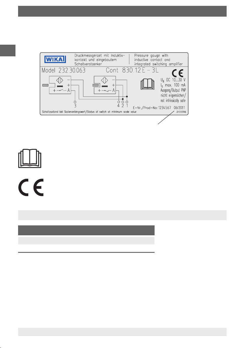
Product label (HYDRA-Gauge with switch contacts)
GB
Explanation of symbols
Before mounting and commissioning the instrument with electronic contacts,
ensure you read the operating instructions!
Date of manufacture
CE, Communauté Européenne
Instruments bearing this mark comply with the relevant European directives.
3. Specications
Permissible working conditions
Ambient temperature +5 ... 60 °C
Process temperature +5 ... 60 °C
■
The mechanical pressure gauge of the HYDRA-Gauge is overpressure safe up to the
full scale value for a short term. However working pressure should not exceed 2/3 of the
measuring range to guarantee a long service life of the pressure gauge.
■
In any case the maximum pressures and temperatures of the process connection
according to the following chart must not be exceeded. The resulting maximum
permissible working pressures might be lower than the instrument's measuring range.
6 WIKA operating instructions HYDRA-Gauge
9015329.01 08/2013 GB/D/F/E
Page 7

3. Specications / 4. Design and function
Permissible process pressure
1/4" and 3/8"
1/2"
Pressure in bar
Temperature in °C
■
The HYDRA-Gauge is not appropriate for strong vibrations, pulsations and pressure
surges, e.g. at measuring points directly behind a pump. Appropriate pulsation dampers
and restrictor segments may be necessary.
■
The HYDRA-Gauge must not be used with aggressive ambient conditions (e.g. HCl
vapours). This may result in corrosion of the metallic parts of the HYDRA-Gauge.
For further specications see WIKA data sheet SP 99.20 and the order documentation.
3/4"
1"
1 1/4"
only up to
25 °C
GB
4. Design and function
4.1 Description
HYDRA-Gauge is a mechanical pressure gauge of nominal size 63 in accordance with
EN 837-1. With a special diaphragm seal system it has been adapted to the special
requirements of ultrapure media distribution systems. All wetted parts are made of PFA
or TFM (modied PTFE). Final assembly, adjustment and packaging is eected under
Laminar-Flow Class 100. Standard system ll uid is KN 75, a 50/50 mixture of DI water and
isopropyl alcohol (IPA). Optionally DI water (KN 64) is used. Pressure gauge and diaphragm
seal are one unit and may never ever be separated as this may cause the system ll uid to
leak, thus destroying the measuring assembly.
4.2 Scope of delivery
Cross-check scope of delivery with the delivery note.
9015329.01 08/2013 GB/D/F/E
WIKA operating instructions HYDRA-Gauge 7
Page 8

5. Transport, packaging ... / 6. Commissioning, operation
5. Transport, packaging and storage
5.1 Transport
GB
Check the instrument for any damage that may have been caused during transportation.
Obvious damage must be reported immediately.
5.2 Packaging
Do not remove packaging until just before mounting.
Keep the packaging as it will provide optimum protection during transport (e.g. change in
installation site, sending for repair).
5.3 Storage
Permissible conditions at the place of storage:
■
Storage temperature: -20 ... +60 °C (standard, KN 75)
+5 ... +60 °C (optional, KN 64)
6. Commissioning, operation
Installation instructions
The recommendations of EN 837-2 regarding selection and installation of pressure
gauges are to be observed. Installation and commissioning may only be carried out by
trained and qualied personnel. When tightening the process connections, observe the
relevant instructions and the advice of the ttings' manufacturers. The measuring instru-
ment's central nut, which is sealed with a colour point, and the threaded connection of the
pressure gauge to the diaphragm seal must not be loosened at any rate. This would cause
the destruction of the measuring assembly and the leakage of the process medium.
8 WIKA operating instructions HYDRA-Gauge
9015329.01 08/2013 GB/D/F/E
Page 9

6. Commissioning ... / 7. HYDRA-Gauge with switch contacts
After installation the pressure gauge may
be turned by hand in order to get an optimal
read-o position.
A pressure measuring instrument with the option of an electrical contact must be
connected in accordance with the connection diagram on the instrument.
For further information see data sheet AC 08.01
360°
7. HYDRA-Gauge with switch contacts
When using the HYDRA-Gauge pressure measuring assemblies with model 830 E
electronic contacts, observe the following:
7.1 Description, application
Direct switching of small capacities which are usually required in connection with a PLC
can be realised by the inductive contact with integrated switching amplier, which is
factory-installed directly into the measuring instrument.
GB
The familiar advantages with inductive contacts, such as an especially safe contact
operation, no wear at all by proximity contact operation as well as virtually no reaction
on the measuring system, thus enabling the accuracy of the indication, are used in this
context, too.
An additional control unit is not required.
The electronic contact with 3-wire design is realised with a PNP output. The operating
voltage is DC 10 ... 30 V. The maximum switching current is 100 mA.
The model 830 E is not intrinsically safe and therefore not suitable for applications in
hazardous areas!
9015329.01 08/2013 GB/D/F/E
WIKA operating instructions HYDRA-Gauge 9
Page 10
7. HYDRA-Gauge with switch contacts
7.2 Special requirements for the installation point
To avoid, amongst other things, switch signal "chatter", it must be ensured that the instruments are mounted free of vibration.
GB
7.3 Electrical connection
The electrical connection must only be made by qualied skilled personnel. The permissible electrical data, connection details and switching functions are given on the product
label axed to the instrument.
The connection cables are appropriately marked.
■
To connect a PLC control unit or for direct switching of small capacities
■
PNP transistor
With PNP switching apparatus, the switched output is a connection towards PLUS. The
load RL between the switched ouput and the MINUS should be selected in a way not to
exceed the maximum switching current of 100 mA.
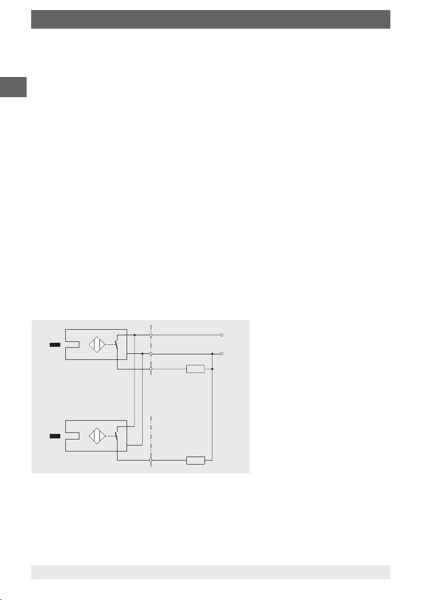
Connection and function circuit diagrams for electronic contact model 830 E,
3-wire system,
control and switching electronics in the sensor,
electrical connection via ying leads
■
Flag emerges from slot
sensor:
Contact open
(output not active)
■
Flag retreats into slot sensor:
Contact closed (output active)
PNP
With double contact
2nd contact
PNP
2
1
3
RL (load)
RL (2nd load)
4
+ U
_
B
10 WIKA operating instructions HYDRA-Gauge
9015329.01 08/2013 GB/D/F/E
Page 11
7. HYDRA-Gauge with switch contacts
7.4 Specications
Range of operating voltage DC 10 ... 30 V
Residual ripple max. 10 %
No-lead current ≤ 10 mA
Switching current ≤ 100 mA
Leakage current ≤ 100 mA
Function of switching element Normally open
Type of output PNP transistor
Voltage drop (with I max.) ≤ 0.7 V
Reverse polarity protection conditional U
Anti-inductive protection 1 kV, 0.1 ms, 1 kΩ
Oscillator frequency approx. 1000 kHz
EMC per EN 60947-5-2
Ambient conditions and temperature in accordance with measuring instrument
Installation installed directly in the measuring instrument at the factory,
Electronic contact model 830 E
(the output 3 or 4 switch must never be set
directly to minus)
maximum 2 switch contacts per measuring instrument
B
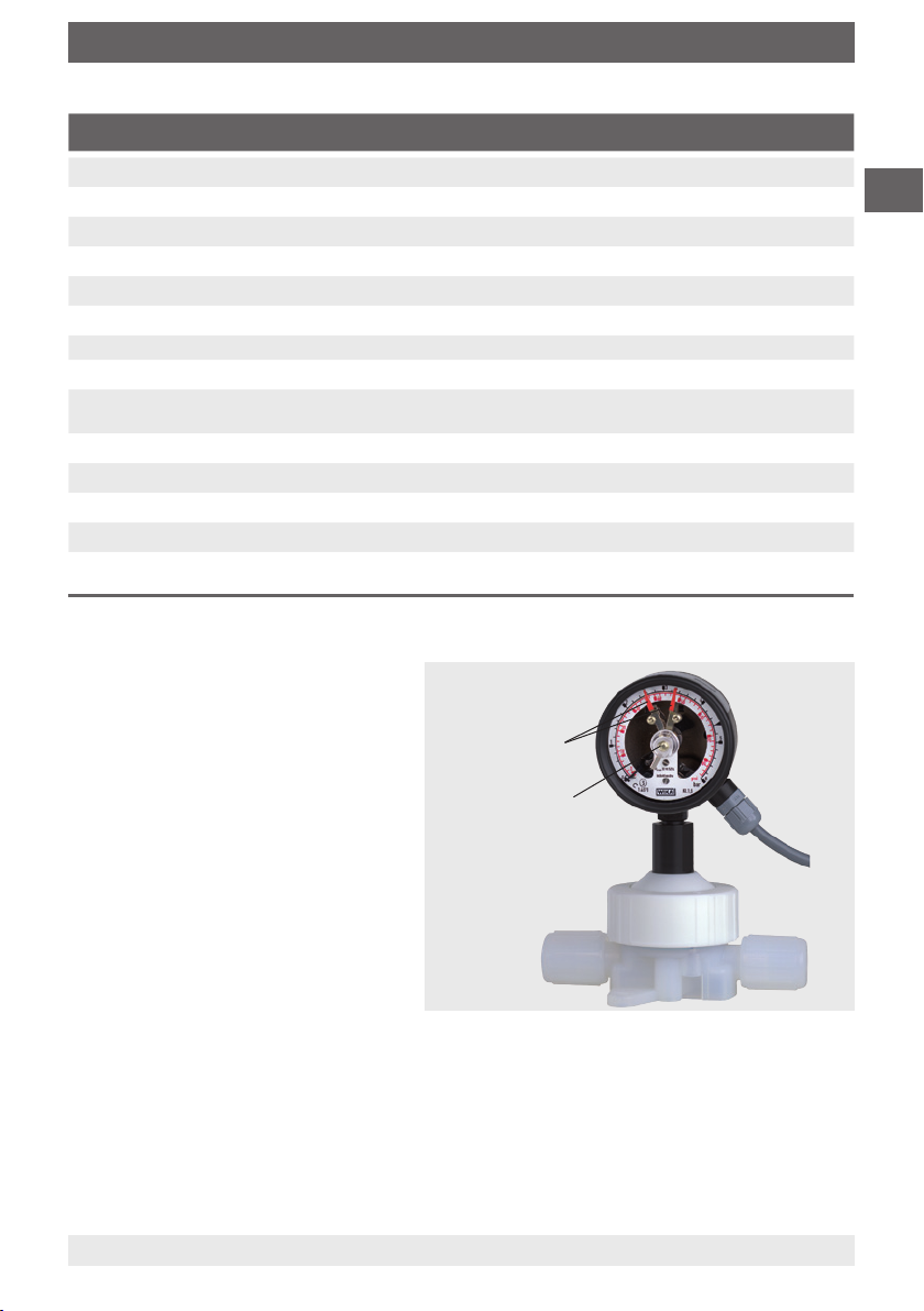
7.5 Adjusting the set pointers
The adjustment of the set points is
achieved using the adjustment lock
in the window with the aid of the
Set pointer
adjustment key (included in delivery).
Adjustment lock
GB
The set pointers for the limit switches are freely adjustable over the full scale range. For
reasons of switching accuracy and service life of the mechanical measuring systems, the
switch points should be between 10 % and 90 % of the measuring range.
9015329.01 08/2013 GB/D/F/E
WIKA operating instructions HYDRA-Gauge 11
Page 12

8. Maintenance and cleaning / 9. Dismounting and disposal
8. Maintenance and cleaning
8.1 Maintenance
GB
HYDRA-Gauge pressure measuring assemblies are maintenance-free.
The indicator and switching function should be checked once or twice every year.
The instrument must be disconnected from the process to check the indication and switching function with a pressure testing device.
The HYDRA double diaphragm system prevents contamination of the process medium
even in case of mechanical damage of the wetted diaphragm. In this case the process
medium will penetrate the lateral leakage bore. The instrument must be exchanged as soon
as possible.
For safety reasons repairs of already installed instruments are not possible.
8.2 Cleaning
CAUTION!
■
The HYDRA-Gauge may only be cleaned by rinsing. Any mechanical
cleaning inside the process connection may damage the separating
diaphragms.
■
Clean the instrument with a moist cloth.
■
Electrical connections must not come into contact with moisture.
9. Dismounting and disposal
WARNING!
Residual media in dismounted instruments can result in a risk to persons, the
environment and equipment.
Take sucient precautionary measures.
9.1 Dismounting
Only disconnect the pressure gauge once the system has been depressurised!
9.2 Disposal
Incorrect disposal can put the environment at risk.
Dispose of instrument components and packaging materials in an environmentally
compatible way and in accordance with the country-specic waste disposal regulations.
12 WIKA operating instructions HYDRA-Gauge
9015329.01 08/2013 GB/D/F/E
Page 13

Inhalt
Inhalt
1. Allgemeines 14
2. Sicherheit 15
3. Technische Daten 16
4. Aufbau und Funktion 17
5. Transport, Verpackung und Lagerung 18
6. Inbetriebnahme, Betrieb 18
7. HYDRA-Gauge mit Schaltkontakten 19
8. Wartung und Reinigung 22
9. Demontage und Entsorgung 22
D
9015329.01 08/2013 GB/D/F/E
WIKA Betriebsanleitung HYDRA-Gauge 13
Page 14

1. Allgemeines
1. Allgemeines
■
Das in der Betriebsanleitung beschriebene Druckmessgerät wird nach dem aktuellen
Stand der Technik konstruiert und gefertigt.
Alle Komponenten unterliegen während der Fertigung strengen Qualitäts- und Umwelt-
kriterien. Unsere Managementsysteme sind nach ISO 9001 und ISO 14001 zertiziert.
D
■
Diese Betriebsanleitung gibt wichtige Hinweise zum Umgang mit dem Gerät. Voraussetzung für sicheres Arbeiten ist die Einhaltung aller angegebenen Sicherheitshinweise
und Handlungsanweisungen.
■
Die für den Einsatzbereich des Gerätes geltenden örtlichen Unfallverhütungsvorschriften und allgemeinen Sicherheitsbestimmungen einhalten.
■
Die Betriebsanleitung ist Produktbestandteil und muss in unmittelbarer Nähe des
Gerätes für das Fachpersonal jederzeit zugänglich aufbewahrt werden.
■
Das Fachpersonal muss die Betriebsanleitung vor Beginn aller Arbeiten sorgfältig
durchgelesen und verstanden haben.
■
Die Haftung des Herstellers erlischt bei Schäden durch bestimmungswidrige Verwen-
dung, Nichtbeachten dieser Betriebsanleitung, Einsatz ungenügend qualizierten
Fachpersonals sowie eigenmächtiger Veränderung am Gerät.
■
Es gelten die allgemeinen Geschäftsbedingungen in den Verkaufsunterlagen.
■
Technische Änderungen vorbehalten.
■
Weitere Informationen:
- Internet-Adresse: www.wika.de / www.wika.com
- zugehöriges Datenblatt: SP 99.20
- Anwendungsberater:
Tel.: +49 9372 132-0
Fax: +49 9372 132-406
info@wika.de
Symbolerklärung
WARNUNG!
… weist auf eine möglicherweise gefährliche Situation hin, die zum Tod oder
zu schweren Verletzungen führen kann, wenn sie nicht gemieden wird.
VORSICHT!
… weist auf eine möglicherweise gefährliche Situation hin, die zu geringfügigen oder leichten Verletzungen bzw. Sach- und Umweltschäden führen
kann, wenn sie nicht gemieden wird.
Information
… hebt nützliche Tipps und Empfehlungen sowie Informationen für einen
ezienten und störungsfreien Betrieb hervor.
WIKA Betriebsanleitung HYDRA-Gauge14
9015329.01 08/2013 GB/D/F/E
Page 15

2. Sicherheit
2. Sicherheit
WARNUNG!
Vor Montage, Inbetriebnahme und Betrieb sicherstellen, dass das richtige
Druckmessgerät hinsichtlich Messbereich, Ausführung und spezischen
Messbedingungen ausgewählt wurde.
Bei Nichtbeachten können schwere Körperverletzungen und/oder
Sachschäden auftreten.
Weitere wichtige Sicherheitshinweise benden sich in den einzelnen Kapiteln
dieser Betriebsanleitung.
2.1 Bestimmungsgemäße Verwendung
Diese Druckmessgeräte dienen zum Messen von Druck bei UHP-Anwendungen z. B. in
der Halbleiterindustrie oder für Reinstchemieversorgungssysteme.
Das Druckmessgerät ist ausschließlich für den hier beschriebenen bestimmungsgemäßen
Verwendungszweck konzipiert und konstruiert und darf nur dementsprechend verwendet
werden.
Ansprüche jeglicher Art aufgrund von nicht bestimmungsgemäßer Verwendung sind
ausgeschlossen.
D
2.2 Personalqualikation
WARNUNG!
Verletzungsgefahr bei unzureichender Qualikation!
Unsachgemäßer Umgang kann zu erheblichen Personen- und Sachschäden
führen.
■
Die in dieser Betriebsanleitung beschriebenen Tätigkeiten nur durch
Fachpersonal nachfolgend beschriebener Qualikation durchführen
lassen.
Fachpersonal
Das Fachpersonal ist aufgrund seiner fachlichen Ausbildung, seiner Kenntnisse der Mess-
und Regelungstechnik und seiner Erfahrungen sowie Kenntnis der landesspezischen
Vorschriften, geltenden Normen und Richtlinien in der Lage, die beschriebenen Arbeiten
auszuführen und mögliche Gefahren selbstständig zu erkennen.
2.3 Besondere Gefahren
WARNUNG!
Messstoreste in ausgebauten Geräten können zur Gefährdung von
Personen, Umwelt und Einrichtung führen.
Ausreichende Vorsichtsmaßnahmen ergreifen.
9015329.01 08/2013 GB/D/F/E
WIKA Betriebsanleitung HYDRA-Gauge 15
Page 16

2. Sicherheit / 3. Technische Daten
2.4 Beschilderung / Sicherheitskennzeichnungen
Typenschild (HYDRA-Gauge mit Schaltkontakten)
D
Symbolerklärung
Vor Montage und Inbetriebnahme des Gerätes mit Elektronik-Kontakten
unbedingt die Betriebsanleitung lesen!
CE, Communauté Européenne
Geräte mit dieser Kennzeichnung stimmen überein mit den zutreenden
europäischen Richtlinien.
Herstellungsdatum
3. Technische Daten
Zulässige Betriebsparameter
Umgebungstemperatur +5 ... 60 °C
Prozesstemperatur +5 ... 60 °C
■
Das mechanische Druckmessgerät des HYDRA-Gauge ist kurzzeitig bis zum
Skalenendwert belastbar. Um eine lange Lebensdauer des Druckmessgerätes zu
gewährleisten, sollte der Betriebsdruck jedoch nicht mehr als 2/3 des Messbereiches
betragen.
■
In jedem Fall dürfen die Maximaldrücke und Temperaturen des Prozessanschlusses
entsprechend dem folgendem Diagramm nicht überschritten werden. Die sich daraus
ergebenden maximal zulässigen Betriebsdrücke können unter Umständen niedriger
sein als der Messbereich.
WIKA Betriebsanleitung HYDRA-Gauge16
9015329.01 08/2013 GB/D/F/E
Page 17

3. Technische Daten / 4. Aufbau und Funktion
Zulässiger Prozessdruck
1/4" und 3/8"
1/2"
Druck in bar
Temperatur in °C
■
Das HYDRA-Gauge ist nicht geeignet bei Auftreten von starken Vibrationen,
3/4"
1"
1 1/4" nur bis 25 °C
Pulsationen und Druckstößen, wie sie z.B. bei Messstellen direkt hinter einer Pumpe
auftreten. Gegebenenfalls sind geeignete Pulsationsdämper und Drosselstrecken
vorzusehen.
■
Das HYDRA-Gauge ist nicht geeignet bei aggressiven Umgebungsbedingungen
(z. B. HCl-Dämpfe). Hier kann es zu Korrosion der metallischen Bauteile von HYDRAGauge kommen.
Weitere technische Daten siehe WIKA Datenblatt SP 99.20 und Bestellunterlagen.
4. Aufbau und Funktion
4.1 Beschreibung
Bei HYDRA-Gauge handelt es sich um ein mechanisches Druckmessgerät der
Nenngröße 63 entsprechend den Vorschriften der EN 837-1. Dieses ist durch ein spezielles
Druckmittlersystem an die besonderen Anforderungen in der Reinstmedienversorgung
angepasst worden. Alle messstoberührten Teile sind aus PFA oder TFM (modiziertes
PTFE). Endmontage, Justage und Verpackung erfolgt unter Laminar-Flow Class 100. Die
Standard-Druckübertragungsüssigkeit ist KN 75, eine Mischung aus 50 % DI-Wasser und
50 % Isopropylalkohol (IPA). Optional wird DI-Wasser (KN 64) eingesetzt. Druckmessgerät
und Druckmittler sind eine Einheit und dürfen auf keinen Fall getrennt werden. Dies würde
zu einem Austritt von Druckübertragungsüssigkeit und somit zu einer Zerstörung der
Druckmessanordnung führen.
D
4.2 Lieferumfang
Lieferumfang mit dem Lieferschein abgleichen.
9015329.01 08/2013 GB/D/F/E
WIKA Betriebsanleitung HYDRA-Gauge 17
Page 18

5. Transport, Verpackung ... / 6. Inbetriebnahme, Betrieb
5. Transport, Verpackung und Lagerung
5.1 Transport
Gerät auf eventuell vorhandene Transportschäden untersuchen.
Oensichtliche Schäden unverzüglich mitteilen.
D
5.2 Verpackung
Verpackung erst unmittelbar vor der Montage entfernen.
Die Verpackung aufbewahren, denn diese bietet bei einem Transport einen optimalen
Schutz (z. B. wechselnder Einbauort, Reparatursendung).
5.3 Lagerung
Zulässige Bedingungen am Lagerort:
■
Lagertemperatur: -20 ... +60 °C (Standard, KN 75)
+5 ... +60 °C (optional, KN 64)
6. Inbetriebnahme, Betrieb
Montagehinweise
Die Empfehlungen der EN 837-2 zur Auswahl und Einbau von Druckmessgeräten sind
einzuhalten. Die Montage und Inbetriebnahme darf nur von entsprechend qualiziertem
Fachpersonal durchgeführt werden. Beim Verschrauben der Prozessanschlüsse sind die
einschlägigen Vorschriften sowie die Empfehlungen der Fittinghersteller einzuhalten. Die
mit einem Farbpunkt versiegelte Zentralmutter des Messgerätes sowie die Verschraubung
des Manometers mit dem Druckmittler dürfen auf keinen Fall gelöst werden. Dies führt zu
einer Zerstörung der Messanordnung und zum Austreten von Prozessmedium.
9015329.01 08/2013 GB/D/F/E
WIKA Betriebsanleitung HYDRA-Gauge18
Page 19

6. Inbetriebnahme ... / 7. HYDRA-Gauge mit Schaltkontakten
Nach der Montage kann das Druckmessgerät von Hand verdreht werden, um ihn in eine
zum Ablesen optimale Position zu bringen.
Ist das Druckmessgerät mit der Option elektrischer Kontakt versehen, so ist dieser
entsprechend dem auf dem Gerät angebrachten Anschlussplan anzuschließen.
Weitere Informationen siehe Datenblatt AC 08.01
360°
7. HYDRA-Gauge mit Schaltkontakten
Bei Einsatz von HYDRA-Gauge Druckmessanordnungen mit Elektronik-Kontakt Typ 830 E
ist Folgendes zu beachten:
7.1 Beschreibung, Einsatz
Durch den werkseitig direkt in das Messgerät eingebauten Induktivkontakt mit integriertem
Schaltverstärker Typ 830 E können kleine Leistungen, wie beispielsweise bei speicherprogrammierbaren Steuerungen (SPS) üblich, direkt geschaltet werden.
D
Die von den Induktivkontakten bekannten Vorteile, wie besonders sichere Kontaktgabe,
keinerlei Verschleiß durch berührungslose Kontaktgabe sowie praktisch keine Rückwirkungen auf das Messsystem, werden auch hier genutzt.
Ein zusätzliches Steuergerät ist nicht erforderlich.
Der Elektronik-Kontakt ist in 3-Leiter-Technik mit einem PNP-Ausgang realisiert, wobei der
Betriebsspannungsbereich DC 10 ... 30 V beträgt und der maximale Schaltstrom 100 mA
ist.
Elektronik-Kontakt Typ 830 E ist nicht eigensicher und deshalb nicht geeignet für Anwendungen in explosionsgefährdeten Bereichen!
9015329.01 08/2013 GB/D/F/E
WIKA Betriebsanleitung HYDRA-Gauge 19
Page 20

7. HYDRA-Gauge mit Schaltkontakten
7.2 Besondere Anforderungen an die Einbaustelle
Um u.a. ein „Flattern“ des Schaltsignals zu vermeiden, ist dafür zu sorgen, dass die Geräte
erschütterungsfrei montiert sind.
7.3 Elektrischer Anschluss
D
Der elektrische Anschluss darf nur durch qualiziertes Personal erfolgen. Die zulässigen
Anschlusswerte, Belegung der Anschlüsse und die Schaltfunktionen sind dem Typenschild, welches am Gerät angebracht ist, zu entnehmen.
Die Anschlusskabel sind entsprechend gekennzeichnet.
■
Zum Anschluss einer SPS-Steuereinheit bzw. zum direkten Schalten kleiner Leistungen
■
PNP-Transistor
Bei PNP-schaltenden Geräten stellt der geschaltete Ausgang eine Verbindung nach
PLUS dar. Die Last R
wählen, dass der max. Schaltstrom von 100 mA nicht überschritten wird.
Anschluss- und Funktionsschaltbild für Elektronik-Kontakt Typ 830 E,
3-Leiter-Ausführung,
Steuer- und Schaltelektronik im Initiator,
elektrischer Anschluss über freies Kabelende
zwischen dem geschalteten Ausgang und dem MINUS ist so zu
L
PNP
Bei Zweifachkontakt
2. Kontakt
PNP
2
1
3
RL (Last)
RL (2. Last)
4
+ U
_
WIKA Betriebsanleitung HYDRA-Gauge20
■
Steuerfahne aus dem
B
Schlitzinitiator:
Kontakt oen
(Ausgang nicht aktiv)
■
Steuerfahne im
Schlitzinitiator:
Kontakt geschlossen
(Ausgang aktiv)
9015329.01 08/2013 GB/D/F/E
Page 21

7. HYDRA-Gauge mit Schaltkontakten
7.4 Technische Daten
Betriebsspannungsbereich DC 10 ... 30 V
Restwelligkeit max. 10 %
Leerlaufstrom ≤ 10 mA
Schaltstrom ≤ 100 mA
Reststrom ≤ 100 mA
Schaltelementefunktion Schließer
Ausgangsart PNP-Transistor
Spannungsabfall (bei I max.) ≤ 0,7 V
Verpolungsschutz bedingt U
Induktionsschutz 1 kV, 0,1 ms, 1 kΩ
Oszillatorfrequenz ca. 1000 kHz
EMV gemäß EN 60947-5-2
Umgebungsbedingungen und
-temperatur
Einbau werkseitig direkt in das Messgerät,
Elektronik-Kontakt Typ 830 E
(der geschaltete Ausgang 3 oder 4 darf niemals
direkt auf Minus gelegt werden)
entsprechend Messgerät
maximal 2 Schaltkontakte je Messgerät
B
7.5 Einstellen der Sollwertzeiger
Das Einstellen der Sollwerte
erfolgt über das Verstellschloss
in der Sichtscheibe mit Hilfe des
Sollwertzeiger
Verstellschlüssels (gehört zum
Lieferumfang).
Verstellschloss
D
Die Sollwertzeiger der Grenzwertschalter sind im gesamten Skalenbereich frei
einstellbar. Aus Gründen der Schaltgenauigkeit und der Lebensdauer der mechanischen
Messsysteme sollen die Schaltpunkte zwischen 10 % und 90 % der Messspanne liegen.
9015329.01 08/2013 GB/D/F/E
WIKA Betriebsanleitung HYDRA-Gauge 21
Page 22

8. Wartung und Reinigung /
9. Demontage und Entsorgung
8. Wartung und Reinigung
8.1 Wartung
HYDRA-Gauge Druckmessanordnungen sind wartungsfrei.
Eine Überprüfung der Anzeige und der Schaltfunktion sollte etwa 1 bis 2 mal pro Jahr
D
erfolgen.
Zur Prüfung von Anzeige und Schaltfunktion ist das Gerät vom Prozess zu trennen und mit
einer Druckprüfvorrichtung zu kontrollieren.
Das HYDRA-Doppelmembransystem verhindert auch bei einer mechanischen Beschädi-
gung der messstoberührenden Membran eine Kontamination des Prozessmediums. In
diesem Fall tritt Prozessmedium zur seitlichen Leckagebohrung aus. Das Gerät ist dann
schnellstmöglich auszuwechseln.
Aus Sicherheitsgründen sind Reparaturen von bereits vor Ort eingebauten Geräten nicht
möglich.
8.2 Reinigung
VORSICHT!
■
Eine Reinigung von HYDRA-Gauge darf nur durch Ausspülen erfolgen.
Jegliche mechanische Reinigung im Inneren des Prozessanschlusses
kann zu einer Beschädigung der Trennmembranen führen.
■
Das Gerät mit einem feuchten Tuch reinigen.
■
Elektrische Anschlüsse nicht mit Feuchtigkeit in Berührung bringen.
9. Demontage und Entsorgung
WARNUNG!
Messstoreste in ausgebauten Geräten können zur Gefährdung von
Personen, Umwelt und Einrichtung führen.
Ausreichende Vorsichtsmaßnahmen sind zu ergreifen.
9.1 Demontage
Druckmessgerät nur im drucklosen Zustand demontieren!
9.2 Entsorgung
Durch falsche Entsorgung können Gefahren für die Umwelt entstehen.
Gerätekomponenten und Verpackungsmaterialien entsprechend den landesspezischen
Abfallbehandlungs- und Entsorgungsvorschriften umweltgerecht entsorgen.
WIKA Betriebsanleitung HYDRA-Gauge22
9015329.01 08/2013 GB/D/F/E
Page 23

Sommaire
Sommaire
1. Généralités 24
2. Sécurité 25
3. Spécications 26
4. Conception et fonction 27
5. Transport, emballage et stockage 28
6. Mise en service, exploitation 28
7. HYDRA-Gauge avec contacts électriques 29
8. Entretien et nettoyage 32
9. Démontage et mise au rebut 32
F
9015329.01 08/2013 GB/D/F/E
WIKA mode d'emploi HYDRA-Gauge 23
Page 24

1. Généralités
1. Généralités
■
Le manomètre décrit dans le présent mode d’emploi est conçu et fabriqué selon les
dernières technologies en vigueur. Tous les composants sont soumis à des critères de
qualité et d’environnement stricts durant la fabrication. Nos systèmes de gestion sont
certiés selon ISO 9001 et ISO 14001.
■
Ce mode d’emploi donne des indications importantes concernant l’utilisation de
l’instrument. Il est possible de travailler en toute sécurité avec ce produit en respectant
F
toutes les consignes de sécurité et d’utilisation.
■
Respecter les prescriptions locales de prévention contre les accidents et les
prescriptions générales de sécurité en vigueur pour le domaine d’application de
l’instrument.
■
Le mode d’emploi fait partie de l’instrument et doit être conservé à proximité immédiate
de l’instrument et accessible à tout moment pour le personnel qualié.
■
Le personnel qualié doit, avant de commencer toute opération, avoir lu soigneusement
et compris le mode d’emploi.
■
La responsabilité du fabricant n’est pas engagée en cas de dommages provoqués par
une utilisation non conforme à l’usage prévu, de non respect de ce mode d’emploi,
d’utilisation de personnel peu qualié de même qu’en cas de modications de
l’instrument eectuées par l’utilisateur.
■
Les conditions générales de vente mentionnées dans les documents de vente
s’appliquent.
■
Sous réserve de modications techniques.
■
Pour obtenir d’autres informations:
- Consulter notre site internet : www.wika.fr
- Fiche technique correspondante : SP 99.20
- Conseiller applications :
Explication des symboles
AVERTISSEMENT !
… indique une situation présentant des risques susceptibles de provoquer
la mort ou des blessures graves si elle n'est pas évitée.
Tel. : +33 1 343084-84
Fax : +33 1 343084-94
info@wika.fr
ATTENTION !
… indique une situation potentiellement dangereuse et susceptible de
provoquer de légères blessures ou des dommages matériels et pour
l'environnement si elle n'est pas évitée.
Information
… met en exergue les conseils et recommandations utiles de même que les
informations permettant d'assurer un fonctionnement ecace et normal.
WIKA mode d'emploi HYDRA-Gauge24
9015329.01 08/2013 GB/D/F/E
Page 25

2. Sécurité
2. Sécurité
AVERTISSEMENT !
Avant le montage, la mise en service et le fonctionnement, s'assurer que
l'indicateur de pression portable et le capteur de pression ont été choisi de
façon adéquate, en ce qui concerne la plage de mesure, la version et les
conditions de mesure spéciques.
Un non-respect de cette consigne peut entraîner des blessures corporelles
graves et/ou des dégâts matériels.
Vous trouverez d'autres consignes de sécurité dans les sections individuelles
du présent mode d'emploi.
2.1 Utilisation conforme à l'usage prévu
Ces manomètres permettent de mesurer la pression dans des applications UHP, par
exemple dans l'industrie des semi-conducteurs ou pour des systèmes de distribution de
produits chimiques ultra-purs.
Le manomètre est conçu et construit exclusivement pour une utilisation conforme à l'usage
prévu décrit ici et ne doit être utilisé qu'en conséquence.
Aucune réclamation ne peut être recevable en cas d'utilisation non conforme à l'usage prévu.
F
2.2 Qualication du personnel
AVERTISSEMENT !
Danger de blessure en cas de qualication insusante !
Une utilisation non conforme peut entraîner d'importants dommages
corporels et matériels.
■
Les opérations décrites dans ce mode d'emploi ne doivent être eectuées
que par un personnel ayant la qualication décrite ci-après.
Personnel qualié
Le personnel qualié est, en raison de sa formation spécialisée, de ses connaissances
dans le domaine de la technique de mesure et de régulation et de ses expériences de
même que de sa connaissance des prescriptions nationales, des normes et directives en
vigueur, en mesure d'eectuer les travaux décrits et de reconnaître automatiquement les
dangers potentiels.
2.3 Dangers particuliers
AVERTISSEMENT !
Les restes de uides se trouvant dans les instruments démontés peuvent
mettre en danger les personnes, l'environnement ainsi que l'installation.
Prendre des mesures de sécurité susantes.
9015329.01 08/2013 GB/D/F/E
WIKA mode d'emploi HYDRA-Gauge 25
Page 26

2. Sécurité / 3. Spécications
2.4 Etiquetage / Marquages de sécurité
Plaque signalétique (HYDRA-Gauge avec contacts électriques)
F
Date de fabrication
Explication des symboles
Lire impérativement le mode d'emploi avant le montage et la mise en service
de l'instrument avec contacts électriques !
CE, Communauté Européenne
Les instruments avec ce marquage sont conformes aux directives
européennes pertinentes.
3. Spécications
Conditions de travail admissibles
Température ambiante +5 ... 60 °C
Température process +5 ... 60 °C
■
Le manomètre mécanique du HYDRA-Gauge est résistant à la surpression pour une
période courte, et ce jusqu'à la valeur de pleine échelle. La pression de travail ne doit
cependant pas excéder les 2/3 de la plage de mesure an de garantir une longue durée
de vie au manomètre.
■
Dans tous les cas, les pressions et températures maximales du raccord process
selon le diagramme suivant ne doivent pas être dépassées. Les pressions de travail
maximales admissibles en résultant pourraient être inférieures à la plage de mesure de
l'instrument.
WIKA mode d'emploi HYDRA-Gauge26
9015329.01 08/2013 GB/D/F/E
Page 27

3. Spécications / 4. Conception et fonction
Pression de traitement admissible
1/4" et 3/8"
1/2"
Pression en bar
Température en °C
■
Le HYDRA-Gauge n'est pas approprié pour des vibrations, pulsations et variations
de pression fortes, par exemple, aux points de mesure placés directement derrière
une pompe. Des amortisseurs de pulsation et des segments restricteur pourraient être
nécessaires.
■
Le HYDRA-Gauge ne doit pas être utilisé dans des conditions ambiantes
agressives (par exemple, des vapeurs de HCI). Cela peut se traduire par une
corrosion des pièces métalliques du HYDRA-Gauge.
Pour de plus amples spécications, voir la che technique WIKA SP 99.20 et la
documentation de commande.
3/4"
1"
1 1/4"
seulement jusqu'à
25 °C
F
4. Conception et fonction
4.1 Description
Le HYDRA-Gauge est un manomètre mécanique de taille nominale 63 conformément à la
norme EN 837-1. Il a été adapté, avec un système spécial de séparateur, aux exigences
particulières des systèmes de distribution de uides ultra-purs. Toutes les pièces en contact
sont en PFA ou en TFM (PTFE modié). Le montage nal, l'ajustement et l'emballage sont
eectués sous écoulement laminaire, classe 100. Le liquide de remplissage du système
standard est KN 75, un mélange 50/50 d'eau DI et d'alcool isopropylique (IPA). En option,
de l'eau DI (KN 64) peut être utilisée. Le manomètre et le séparateur forment une seule
unité et ne doivent jamais être séparés car ceci peut amener le liquide de transmission de
pression à fuir et ainsi à détruire le dispositif de mesure.
4.2 Détail de la livraison
Comparer le détail de la livraison avec le bordereau de livraison.
9015329.01 08/2013 GB/D/F/E
WIKA mode d'emploi HYDRA-Gauge 27
Page 28

5. Transport, emballage ... / 6. Mise en service, exploitation
5. Transport, emballage et stockage
5.1 Transport
Vérier s'il existe des dégâts sur l'instrument liés au transport.
Communiquer immédiatement les dégâts constatés.
5.2 Emballage
N'enlever l'emballage qu'avant le montage.
F
Conserver l'emballage, celui-ci ore, lors d'un transport, une protection optimale (par ex.
changement de lieu d'utilisation, renvoi pour réparation).
5.3 Stockage
Conditions admissibles sur le lieu de stockage :
■
Température de stockage: -20 ... +60 °C (standard, KN 75)
+5 ... +60 °C (optionnel, KN 64)
6. Mise en service, exploitation
Instructions d'installation
Les recommandations de la norme EN 837-2 concernant la sélection et l'installation de
manomètres sont à respecter. L'installation et la mise en service ne doivent être eectuées
que par du personnel spécialisé et qualié. Lors du vissage des raccords process, il
est nécessaire de suivre les instructions pertinentes et les conseils des fabricants des
installations. L'écrou central de l'instrument de mesure scellé par un point de couleur ainsi
que la connexion letée du manomètre avec le séparateur ne doivent en aucun cas être
desserrés. Ceci provoque la destruction du dispositif de mesure et une fuite du uide de
process.
9015329.01 08/2013 GB/D/F/E
WIKA mode d'emploi HYDRA-Gauge28
Page 29

6. Mise en service ... / 7. HYDRA-Gauge avec contacts ...
Après l'installation, le manomètre peut être
tourné à la main an d'obtenir la meilleure
position pour la lecture.
Un instrument de mesure de pression pourvu de l'option d'un contact électrique doit être
connecté conformément au diagramme de connexion appliqué sur l'instrument.
Voir che technique AC 08.01 pour plus d'informations
360°
7. HYDRA-Gauge avec contacts électriques
Lors de l'utilisation des dispositifs de mesure de pression avec des contacts électroniques
type 830 E, observez les points suivants:
7.1 Description, application
Une commutation directe de petites charges requises habituellement en raccordement
avec un PLC peut être réalisée par le contact inductif avec amplicateur de commutation
intégré installé en usine directement dans l'instrument de mesure.
F
Les avantages bien connus des contacts inductifs, tels qu'un fonctionnement de contact
spécialement sûr, aucune usure due à un fonctionnement de contact de proximité de
même qu'une absence virtuelle de réaction sur le système de mesure, permettant ainsi
une grande précision de l'indication, sont utilisés aussi dans ce contexte.
Une unité de commande supplémentaire n'est pas nécessaire.
Le contact électronique avec exécution à trois ls est muni d'une sortie PNP. La tension de
fonctionnement est de 10 à 30 VDC. Le courant de commutation maximum est de 100 mA.
Le type 830 E n'est pas intrinsèquement sûr et donc ne convient pas à des applications
dans des zones dangereuses !
9015329.01 08/2013 GB/D/F/E
WIKA mode d'emploi HYDRA-Gauge 29
Page 30

7. HYDRA-Gauge avec contacts électriques
7.2 Exigences particulières relative au point de montage
Pour éviter, entre autres, un "bégaiement" des signaux de commutation, on doit s'assurer
que les instruments sont montés de manière à éliminer toute vibration.
7.3 Raccordement électrique
Les travaux de raccordement électrique ne doivent être eectués que par des personnels
qualiés. Les données électriques autorisées, les détails de raccordement et les fonctions
de commutation sont indiqués sur l'étiquette du produit apposée sur l'instrument.
F
Les câbles de raccordement sont marqués en conséquence.
■
Pour raccorder une unité de contrôle PLC ou pour une commutation directe de petites
charges
■
Transistor PNP
Avec un équipement de contrôle PNP, la sortie commutée est un raccordement vers
le PLUS. La charge RL entre la sortie commutée et le MOINS devra être choisie de
manière à ne pas dépasser le courant de commutation maximum de 100 mA.
Diagrammes de raccordement et de circuit de fonctionnement pour le
contact électronique type 830 E, système à 3 ls,
électronique de contrôle et de commutation dans le capteur,
raccordement électrique par conducteurs volants
PNP
Avec double contact
2ème contact
PNP
2
1
3
RL (charge)
RL (2ème
charge)
4
+ U
_
■
Un drapeau sort du capteur à
B
fente :
contact ouvert
(sortie pas active)
■
Le drapeau se replie dans le
capteur à fente :
contact fermé (sortie active)
9015329.01 08/2013 GB/D/F/E
WIKA mode d'emploi HYDRA-Gauge30
Page 31

7. HYDRA-Gauge avec contacts électriques
7.4 Spécications
Plage de tension admissible 10 ... 30 VDC
Ondulation résiduelle 10 % maximum
Courant non-conducteur ≤ 10 mA
Courant de commutation ≤ 100 mA
Courant de fuite ≤ 100 mA
Fonctionnement de l'élément de
commutation
Type de sortie Transistor PNP
Baisse de tension (avec I max.) ≤ 0,7 V
Protection contre l'inversion de
polarité
Protection anti-inductive 1 kV, 0,1 ms, 1 kΩ
Fréquence d'oscillateur env. 1000 kHz
EMC selon EN 60947-5-2
Conditions et température ambiantes selon l'instrument de mesure
Installation Installation directement dans l'instrument de mesure en
Contact électrique type 830 E
Normalement ouvert
U
conditionnelle (le commutateur de sortie 3 ou 4 ne doit
B
jamais être réglé directement sur moins)
usine, au maximum 2 contacts électriques par instrument
de mesure
7.5 Réglage de la valeur de
consigne
Le réglage des valeurs de consigne
s'eectue via l'orice de réglage dans
le cadran à l‘aide de la clef de réglage
(fournie avec l'instrument).
Indicateur de
la valeur de
consigne
Orice de réglage
F
Les indicateurs de la valeur de consigne pour les interrupteurs de n de course sont
librement réglables sur toute l'échelle de mesure. Pour des raisons de précision et
de sécurité de commutation, et an de ne pas porter préjudice à la durée de vie des
instruments, il est recommandé de xer les points de commutation entre 10 % et 90 % de
l'étendue de mesure.
9015329.01 08/2013 GB/D/F/E
WIKA mode d'emploi HYDRA-Gauge 31
Page 32

8. Entretien et nettoyage / 9. Démontage et mise au rebut
8. Entretien et nettoyage
8.1 Entretien
Les dispositifs de mesure de pression HYDRA-Gauge sont sans entretien.
Un contrôle de l’achage et de la fonction de commutation est recommandé 1 à 2 fois/an.
Pour contrôler l'achage et la fonction de commutation, l'instrument doit être isolé du
processus de mesure et contrôlé à l'aide d'un dispositif de contrôle de la pression.
F
Le système de membrane double HYDRA empêche la contamination du uide de process,
même dans le cas d'un dommage mécanique de la membrane en contact. Dans ce cas, le
uide de process pénétrera l'orice de fuite latéral. L'instrument doit être remplacé le plus
vite possible.
Pour des raisons de sécurité, il n'est pas possible de réparer des instruments déjà
installés.
8.2 Nettoyage
ATTENTION !
■
Le HYDRA-Gauge ne doit être nettoyé que par rinçage. Tout nettoyage
mécanique dans le raccord process endommagerait les membranes de
séparation.
■
Nettoyer l'instrument avec un chion humide.
■
Eviter tout contact des raccordements électriques avec l'humidité.
9. Démontage et mise au rebut
AVERTISSEMENT !
Les restes de uides se trouvant dans les instruments démontés peuvent
mettre en danger les personnes, l'environnement ainsi que l'installation.
Prendre des mesures de sécurité susantes.
9.1 Démontage
Déconnecter le manomètre uniquement une fois que le système a été mis hors pression.
9.2 Mise au rebut
Une mise au rebut inadéquate peut entraîner des dangers pour l'environnement.
Eliminer les composants des instruments et les matériaux d'emballage conformément
aux prescriptions nationales pour le traitement et l'élimination des déchets et aux lois de
protection de l'environnement en vigueur.
WIKA mode d'emploi HYDRA-Gauge32
9015329.01 08/2013 GB/D/F/E
Page 33

Contenido
Contenido
1. Información general 34
2. Seguridad 35
3. Datos técnicos 36
4. Diseño y función 37
5. Transporte, embalaje y almacenamiento 38
6. Puesta en servicio, funcionamiento 38
7. HYDRA-Gauge con contactos eléctricos 39
8. Mantenimiento y limpieza 42
9. Desmontaje y eliminación 42
E
9015329.01 08/2013 GB/D/F/E
WIKA manual de instrucciones HYDRA-Gauge 33
Page 34

1. Información general
1. Información general
■
El manómetro descrito en el manual de instrucciones está construido y fabricado
según el estado actual de la técnica. Todos los componentes están sujetos a rigurosos
criterios de calidad y medio ambiente durante la producción. Nuestros sistemas de
gestión están certicados según ISO 9001 y ISO 14001.
■
Este manual de instrucciones proporciona indicaciones importantes acerca del manejo
del instrumento. Para un trabajo seguro, es imprescindible cumplir con todas las
instrucciones de seguridad y manejo indicadas.
■
E
Cumplir siempre las normativas sobre la prevención de accidentes y las normas de
seguridad en vigor en el lugar de utilización del instrumento.
■
El manual de instrucciones es una parte integrante del instrumento y debe guardarse
en la proximidad del mismo para que el personal especializado pueda consultarlo en
cualquier momento.
■
El personal especializado debe haber leído y entendido el manual de instrucciones
antes de comenzar cualquier trabajo.
■
El fabricante queda exento de cualquier responsabilidad en caso de daños causados
por un uso no conforme a la nalidad prevista, la inobservancia del presente manual
de instrucciones, un manejo por personal insucientemente cualicado así como una
modicación no autorizada del instrumento.
■
Se aplican las condiciones generales de venta incluidas en la documentación de venta.
■
Modicaciones técnicas reservadas.
■
Para obtener más informaciones consultar:
- Página web: www.wika.es
- Hoja técnica correspondiente: SP 99.20
- Servicio técnico:
Explicación de símbolos
Tel.: +34 933 938-630
Fax: +34 933 938-666
info@wika.es
¡ADVERTENCIA!
... indica una situación probablemente peligrosa que pueda causar la muerte
o lesiones graves si no se evita.
¡CUIDADO!
... indica una situación probablemente peligrosa que pueda causar lesiones
leves o medianas o daños materiales y medioambientales si no se evita.
Información
... destaca consejos y recomendaciones útiles así como informaciones para
una utilización ecaz y libre de fallos.
WIKA manual de instrucciones HYDRA-Gauge34
9015329.01 08/2013 GB/D/F/E
Page 35

2. Seguridad
2. Seguridad
¡ADVERTENCIA!
Antes del montaje, la puesta en servicio y el funcionamiento asegurarse de
que se haya seleccionado el manómetro adecuado con respecto a rango de
medida, versión y condiciones de medición especícas.
El no respetar las instrucciones puede generar lesiones graves y/o daños
materiales.
Los distintos capítulos de este manual de instrucciones contienen otras
importantes indicaciones de seguridad.
2.1 Uso conforme a lo previsto
Estos manómetros son adecuados para medir la presión en aplicaciones UHP, como p. Ej.
en la industria de semiconductores, o para sistemas de alimentación de química purísima.
El manómetro ha sido diseñado y construido únicamente para la nalidad aquí descrita y
debe utilizarse en conformidad a la misma.
No se admite ninguna reclamación debido a un manejo no adecuado.
2.2 Cualicación del personal
¡ADVERTENCIA!
¡Riesgo de lesiones debido a una insuciente cualicación!
Un manejo no adecuado puede causar considerables daños personales y
materiales.
■
Las actividades descritas en este manual de instrucciones deben
realizarse únicamente por personal especializado con la consiguiente
cualicación.
Personal especializado
Debido a su formación profesional, a sus conocimientos de la técnica de regulación
y medición así como a su experiencia y su conocimiento de las normativas, normas y
directivas vigentes en el país de utilización el personal especializado es capaz de ejecutar
los trabajos descritos y reconocer posibles peligros por sí solo.
E
2.3 Riesgos especícos
¡ADVERTENCIA!
Restos de medios en instrumentos desmontados pueden causar riesgos para
personas, medio ambiente e instalación.
Tomar adecuadas medidas de precaución.
9015329.01 08/2013 GB/D/F/E
WIKA manual de instrucciones HYDRA-Gauge 35
Page 36

2. Seguridad / 3. Datos técnicos
2.4 Rótulos / Marcados de seguridad
Placa indicadora (HYDRA-Gauge con contactos eléctricos)
E
Fecha de fabricación
Explicación de símbolos
¡Es absolutamente necesario leer el manual de instrucciones antes del
montaje y la puesta en servicio del instrumento con contactos eléctricos!
CE, Communauté Européenne
Los instrumentos con este marcaje cumplen las directivas europeas
aplicables.
3. Datos técnicos
Parámetros de servicio admisibles
Temperatura ambiental +5 ... 60 °C
Temperatura de proceso +5 ... 60 °C
■
El manómetro mecánico de HYDRA-Gauge puede cargarse brevemente hasta el valor
nal de escala. Sin embargo, a n de garantizar una larga vida útil del manómetro, la
presión de servicio no debe superar 2/3 del rango de medida.
■
En todo caso, no deben sobrepasarse las presiones máximas y temperaturas de la
conexión al proceso conforme al siguiente diagrama. Las presiones máximas de servicio admisibles resultantes de ello pueden ser ocasionalmente inferiores al rango de
medida
WIKA manual de instrucciones HYDRA-Gauge36
9015329.01 08/2013 GB/D/F/E
Page 37

3. Datos técnicos / 4. Diseño y función
Presión de proceso admisible
1/4" et 3/8"
1/2"
Presión en bar
Temperatura en °C
■
El HYDRA-Gauge no es adecuado para aplicaciones con fuertes vibraciones,
pulsaciones y golpes de presión, como p. ej. en puntos de medición situados
directamente en el dorso de una bomba. En caso necesario deben montarse
amortiguadores de pulsación y dispositivos de obturación.
■
El HYDRA-Gauge no es apto para aplicaciones en condiciones (p. Ej. vapores
de HCl). Aquí puede producirse corrosión de los componentes metálicos del
instrumento.
3/4"
1"
1 1/4" sólo hasta 25 °C
E
Para más datos técnicos véase la hoja técnica de WIKA SP 99.20 y la documentación de
pedido.
4. Diseño y función
4.1 Descripción
El HYDRA-Gauge es un manómetro mecánico de diámetro nominal 63 conforme a las
prescripciones de la norma EN 837-1. El mismo ha sido adaptado a los requerimientos de
procesos con medios de alta pureza mediante un sistema de separadores. Todas las partes
en contacto con el medio a medir son de PFA o TFM (PTFE modicado). Montaje nal,
ajuste y embalaje se realizan bajo Laminar-Flow Class 100. El líquido transmisor de presión
estándar es KN 75, una mezcla de 50 % de agua destilada y 50 % de alcohol isopropílico
(IPA). Opcionalmente se emplea agua destilada (KN 64). Manómetro y transmisor de
presión forman una unidad y de ninguna manera deben separarse. Ello provocaría una
pérdida de líquido transmisor de presión y por lo tanto una destrucción de la disposición de
medición de presión.
4.2 Volumen de suministro
Comparar mediante el albarán si se han entregado todas las piezas.
9015329.01 08/2013 GB/D/F/E
WIKA manual de instrucciones HYDRA-Gauge 37
Page 38

5. Transporte, embalaje ... / 6. Puesta en servicio ...
5. Transporte, embalaje y almacenamiento
5.1 Transporte
Comprobar si el instrumento presenta eventuales daños causados en el transporte.
Noticar de inmediato cualquier daño evidente.
5.2 Embalaje
No quitar el embalaje hasta justo antes del montaje.
Guardar el embalaje ya que es la protección ideal durante el transporte (por ejemplo si el
lugar de instalación cambia o si se envía el instrumento para posibles reparaciones).
E
5.3 Almacenamiento
Condiciones admisibles en el lugar de almacenamiento:
■
Temperatura de almacenamiento: -20 ... +60 °C (estándar, KN 75)
+5 ... +60 °C (opcional, KN 64)
6. Puesta en servicio, funcionamiento
Indicaciones de montaje
Deben seguirse las recomendaciones de la norma EN 837-2 para la selección y el
montaje de manómetros. Montaje y puesta en servicio deben estar exclusivamente a
cargo del personal técnico debidamente cualicado. Al atornillar las conexiones al proceso
deben observarse las prescripciones pertinentes, así como las recomendaciones del
fabricante de las piezas de conexión. De ninguna manera debe aojarse la tuerca central
del manómetro, marcada con un punto de color, como tampoco la unión atornillada
del manómetro con el transmisor de presión. Esto ocasionaría una destrucción de la
disposición de medición y un escape del medio de proceso.
9015329.01 08/2013 GB/D/F/E
WIKA manual de instrucciones HYDRA-Gauge38
Page 39

6. Puesta en servicio ... / 7. HYDRA-Gauge con contactos ...
Tras el montaje puede girarse el manómetro
con la mano a n de llevarlo a una posición
óptima para su lectura.
Si el manómetro está dotado de la opción de contacto eléctrico, éste debe conectarse
conforme al esquema de conexión que se encuentra en el instrumento.
Para mas informaciones véase la hoja técnica AC 08.01
360°
7. HYDRA-Gauge con contactos eléctricos
Al utilizar disposiciones de medición HYDRA-Gauge con contacto electrónico tipo 830 E
debe tenerse en cuenta lo siguiente:
7.1 Descripción, utilización
Debido al contacto inductivo con amplicador de conmutación incorporado, modelo 830
E, integrado directamente en fábrica en el instrumento de medición, se pueden conmutar
directamente leves potencias habituales, por ejemplo en controles lógicos programables
(PLC).
E
Aquí se aprovechan las conocidas ventajas de los contactos inductivos, como la conmuta-
ción able sin desgaste, provocado por efectos redundantes al sistema de medición.
Un equipo de adicional de control no es necesario.
El contacto electrónico está disponible con 3 conmutadores con salida PNP. El rango de
tensiones de servicio es de DC 10 ... 30 V, y la corriente de conmutación máxima de
100 mA.
¡El contacto electrónico 830 E no es de seguridad intrínseca y por lo tanto no es
adecuado para el uso en atmósferas potencialmente explosivas!
9015329.01 08/2013 GB/D/F/E
WIKA manual de instrucciones HYDRA-Gauge 39
Page 40

7. HYDRA-Gauge con contactos eléctricos
7.2 Requerimientos especiales en el lugar de instalación
Para prevenir, por ejemplo la oscilación de la señal de conmutación, asegurarse de que
los instrumentos estén montados libre de vibraciones.
7.3 Conexión eléctrica
La conexión eléctrica sólo la puede realizar personal cualicado. Consultar la placa
indicadora de tipo del instrumento para los valores de conexión permitidos, la asignación
de pin y las funciones de conmutación.
Los cables de conexión están debidamente identicados.
E
■
Para conectar una unidad de control PLC o para conmutar potencias bajas
directamente
■
Transistor PNP
En combinación con transistores PNP, la salida representa una conexión con el polo
POSITIVO. Seleccione la carga RL entre la salida conmutada y el polo NEGATIVO de
tal forma que no se exceda la corriente máxima de conmutación de 100 mA.
Esquema de conexiones y funciones para contactos electrónicos del modelo 830
E, versión de 3 conductores, sistema electrónico de control y conmutación en el
sensor de proximidad, conexión eléctrica mediante cable pelado
PNP
Con contacto doble
2º contacto
PNP
2
1
3
RL (carga)
4
RL
(2a carga)
WIKA manual de instrucciones HYDRA-Gauge40
+ U
_
■
La bandera de control se
B
encuentra en el exterior
de la ranura del iniciador:
El contacto está abierto
(salida desactivada).
■
La bandera de control se
encuentra en el interior
de la ranura del iniciador:
El contacto está cerrado
(salida activada)
9015329.01 08/2013 GB/D/F/E
Page 41

7. HYDRA-Gauge con contactos eléctricos
7.4 Datos técnicos
Rango de tensiones de servicio DC 10 ... 30 V
Ondulación residual máx. 10 %
Corriente en vacío ≤ 10 mA
Corriente de conmutación ≤ 100 mA
Corriente residual ≤ 100 mA
Función del elemento de
conmutación
Tipo de salida Transistor PNP
Caída de tensión (con I máx.) ≤ 0,7 V
Protección contra inversión de
polaridad
Antiinducción 1 kV, 0,1 ms, 1 kΩ
Frequencia de oscilación aprox. 1000 kHz
CEM conforme a EN 60947-5-2
Condiciones ambientales y
temperatura ambiente
Instalación en la fábrica directamente en el instrumento de medición,
Contacto electrónico modelo 830 E
Contacto normalmente abierto
condiciona U
directamente al polo negativo)
dependiendo del instrumento de medición
máx. 2 contactos eléctricos por instrumento de medición
(nunca conectar las salidas 3 ó 4
B
7.5 Ajuste de los indicadores de
valor nominal
El ajuste de los valores nominales se
hace a través del cierre de ajuste en
la mirilla, utilizando la llave de ajuste
(incluido en el suministro).
Indicador de
valor nominal
Cierre de ajuste
E
Los indicadores de valor nominal de los contactos de alarma pueden ajustarse en toda la
escala. Por razones de precisión de conmutación y vida útil de los sistemas mecánicos
de medición, se recomienda jar los puntos de conmutación entre el 10 % y el 90 % del
alcance de medición.
9015329.01 08/2013 GB/D/F/E
WIKA manual de instrucciones HYDRA-Gauge 41
Page 42

8. Mantenimiento y limpieza / 9. Desmontaje y eliminación
8. Mantenimiento y limpieza
8.1 Mantenimiento
Las disposiciones de medición de presión HYDRA-Gauge no requieren mantenimiento.
Controlar el instrumento y la función de conmutación una o dos veces al año.
Para la revisión del instrumento y la comprobación de la función de conmutación hay que
desconectar el instrumento del proceso y controlarlo con un dispositivo de control de
presión.
El sistema de doble membrana HYDRA previene una contaminación del medio de proceso
E
incluso en caso de un deterioro mecánico de la membrana en contacto con el medio de
medición. En tal caso, se produce un escape del medio de proceso hacia el taladro de
fuga lateral. El instrumento debe reemplazarse entonces lo más rápido posible.
Por razones de seguridad no es posible efectuar reparaciones en instrumentos montados
ya in situ.
8.2 Limpieza
¡CUIDADO!
■
La limpieza del HYDRA-Gauge debe realizarse solamente mediante una
purga. Cualquier limpieza mecánica en el interior de la conexión al proceso
puede provocar un deterioro de las membranas de separación.
■
Limpiar el instrumento con un trapo húmedo.
■
Asegurarse de que las conexiones eléctricas no se humedecen.
9. Desmontaje y eliminación
¡ADVERTENCIA!
Restos de medios en instrumentos desmontados pueden causar riesgos
para personas, medio ambiente e instalación.
Tomar adecuadas medidas de precaución.
9.1 Desmontaje
¡Desmontar el manómetro sólo si no está sometido a presión!
9.2 Eliminación de residuos
Una eliminación incorrecta puede provocar peligros para el medio ambiente.
Eliminar los componentes de los instrumentos y los materiales de embalaje conforme a
los reglamentos relativos al tratamiento de residuos y eliminación vigentes en el país de
utilización.
WIKA manual de instrucciones HYDRA-Gauge42
9015329.01 08/2013 GB/D/F/E
Page 43

WIKA global
Europe
Austria
WIKA Messgerätevertrieb
Ursula Wiegand GmbH & Co.
KG
Perfektastr. 83
1230 Vienna
Tel. +43 1 8691631
Fax: +43 1 8691634
info@wika.at
www.wika.at
Belarus
WIKA Belrus
Ul. Zaharova 50B, Oce 3H
220088 Minsk
Tel. +375 17 2945711
Fax: +375 17 2945711
info@wika.by
www.wika.by
Benelux
WIKA Benelux
Industrial estate De Berk
Newtonweg 12
6101 WX Echt
Tel. +31 475 535500
Fax: +31 475 535446
info@wika.nl
www.wika.nl
Bulgaria
WIKA Bulgaria EOOD
Akad.Ivan Geshov Blvd. 2E
Business Center Serdika
1330 Soa
Tel. +359 2 82138-10
Fax: +359 2 82138-13
info@wika.bg
www.wika.bg
Croatia
WIKA Croatia d.o.o.
Hrastovicka 19
10250 Zagreb-Lucko
Tel. +385 1 6531-034
Fax: +385 1 6531-357
info@wika.hr
www.wika.hr
9015329.01 08/2013 GB/D/F/E
Finland
WIKA Finland Oy
Melkonkatu 24
00210 Helsinki
Tel. +358 9 682492-0
Fax: +358 9 682492-70
info@wika.
www.wika.
France
WIKA Instruments s.a.r.l.
Parc d‘Aaires des Bellevues
8 rue Rosa Luxembourg
95610 Eragny-sur-Oise
Tel. +33 1 343084-84
Fax: +33 1 343084-94
info@wika.fr
www.wika.fr
Germany
WIKA Alexander Wiegand SE
& Co. KG
Alexander-Wiegand-Str. 30
63911 Klingenberg
Tel. +49 9372 132-0
Fax: +49 9372 132-406
info@wika.de
www.wika.de
Italy
WIKA Italia S.r.l. & C. S.a.s.
Via G. Marconi 8
20020 Arese (Milano)
Tel. +39 02 93861-1
Fax: +39 02 93861-74
info@wika.it
www.wika.it
Poland
WIKA Polska S.A.
Ul. Legska 29/35
87-800 Wloclawek
Tel. +48 54 230110-0
Fax: +48 54 230110-1
info@wikapolska.pl
www.wikapolska.pl
Romania
WIKA Instruments Romania
S.R.L.
050897 Bucuresti
Calea Rahovei Nr. 266-268
Corp 61, Etaj 1
Tel. +40 21 4048327
Fax: +40 21 4563137
m.anghel@wika.ro
www.wika.ro
Russia
ZAO WIKA MERA
Wjatskaya Str. 27, Building 17
Oce 205/206
127015 Moscow
Tel. +7 495-648018-0
Fax: +7 495-648018-1
info@wika.ru
www.wika.ru
Serbia
WIKA Merna Tehnika d.o.o.
Sime Solaje 15
11060 Beograd
Tel. +381 11 2763722
Fax: +381 11 753674
info@wika.rs
www.wika.rs
Spain
Instrumentos WIKA S.A.U.
C/Josep Carner, 11-17
08205 Sabadell Barcelona
Tel. +34 933 9386-30
Fax: +34 933 9386-66
info@wika.es
www.wika.es
Switzerland
MANOMETER AG
Industriestrasse 11
6285 Hitzkirch
Tel. +41 41 91972-72
Fax: +41 41 91972-73
info@manometer.ch
www.manometer.ch
Turkey
WIKA Instruments Istanbul
Basinc ve Sicaklik Ölcme
Cihazlari
Ith. Ihr. ve Tic. Ltd. Sti.
Bayraktar Bulvari No. 17
34775 Yukari Dudullu - Istanbul
Tel. +90 216 41590-66
Fax: +90 216 41590-97
info@wika.com.tr
www.wika.com.tr
Ukraine
TOV WIKA Prylad
M. Raskovoy Str. 11, A
PO 200
02660 Kyiv
Tel. +38 044 4968380
Fax: +38 044 4968380
info@wika.ua
www.wika.ua
43WIKA operating instructions HYDRA-Gauge
Page 44

WIKA global
United Kingdom
WIKA Instruments Ltd
Merstham, Redhill RH13LG
Tel. +44 1737 644-008
Fax: +44 1737 644-403
info@wika.co.uk
www.wika.co.uk
North America
Canada
WIKA Instruments Ltd.
Head Oce, 3103 Parsons
Road
Edmonton, Alberta, T6N 1C8
Tel. +1 780 4637035
Fax: +1 780 4620017
info@wika.ca
www.wika.ca
Mexico
Instrumentos WIKA Mexico
S.A. de C.V.
Viena 20 Ofna 301
Col. Juarez, Del. Cuauthemoc
06600 Mexico D.F.
Tel. +52 55 50205300
Fax: +52 55 50205300
ventas@wika.com
www.wika.com.mx
USA
WIKA Instrument, LP
1000 Wiegand Boulevard
Lawrenceville, GA 30043
Tel. +1 770 5138200
Fax: +1 770 3385118
info@wika.com
www.wika.com
WIKA Process Solutions, LP.
950 Hall Court
Deer Park, TX 77536
Tel. +1 713 47500-22
Fax: +1 713 47500-11
info@wikahouston.com
www.wika.com
Mensor Corporation
201 Barnes Drive
San Marcos, TX 78666
Tel. +1 512 396-4200
Fax: +1 512 396-1820
sales@mensor.com
www.mensor.com
Latin America
Argentina
WIKA Argentina S.A.
Gral. Lavalle 3568
(B1603AUH) Villa Martelli
Buenos Aires
Tel. +54 11 47301800
Fax: +54 11 47610050
info@wika.com.ar
www.wika.com.ar
Brazil
WIKA do Brasil
Av. Ursula Wiegand, 03
CEP 18560-000 Iperó - SP
Tel. +55 15 34599700
Fax: +55 15 32661650
vendas@wika.de
www.wika.com.br
Chile
WIKA Chile S.p.A.
Av. Coronel Pereira 72, Ocina
101
Las Condes - Santiago de Chile
Tel. +56 2 365-1719
info@wika.cl
www.wika.cl
Ind. e Com. Ltda.
Further WIKA subsidiaries worldwide can be found online at www.wika.com.
Weitere WIKA-Niederlassungen weltweit nden Sie online unter www.wika.de.
La liste des autres liales WIKA dans le monde se trouve sur www.wika.fr.
Otras sucursales WIKA en todo el mundo puede encontrar en www.wika.es.
WIKA Alexander Wiegand SE & Co. KG
Alexander-Wiegand-Straße 30
63911 Klingenberg • Germany
Tel. +49 9372 132-0
Fax +49 9372 132-406
info@wika.de
www.wika.de
44 WIKA operating instructions HYDRA-Gauge
9015329.01 08/2013 GB/D/F/E
 Loading...