

Page 1
Operating instructions
Betriebsanleitung
Mode d'emploi
Manual de instrucciones
Pressure transmitter, model HP-2
Druckmessumformer, Typ HP-2
Transmetteur de pression, type HP-2
Transmisor de presión, modelo HP-2
GB
D
F
E
Pressure transmitter for highest pressure, model HP-2
Page 2

GB
Operating instructions model HP-2 Page
3 - 22
D
Betriebsanleitung Typ HP-2 Seite
F
Mode d'emploi type HP-2 Page
Manual de instrucciones modelo HP-2 Página
E
© 2012 WIKA Alexander Wiegand SE & Co. KG
All rights reserved. / Alle Rechte vorbehalten.
®
WIKA
is a registered trademark in various countries.
®
WIKA
ist eine geschützte Marke in verschiedenen Ländern.
23 - 42
43 - 62
63 - 82
Prior to starting any work, read the operating instructions!
Keep for later use!
Vor Beginn aller Arbeiten Betriebsanleitung lesen!
Zum späteren Gebrauch aufbewahren!
Lire le mode d'emploi avant de commencer toute opération !
A conserver pour une utilisation ultérieure !
¡Leer el manual de instrucciones antes de comenzar cualquier trabajo!
¡Guardar el manual para una eventual consulta!
2
WIKA operating instructions pressure transmitter, model HP-2
11379180.03 09/2013 GB/D/F/E
Page 3

Contents
Contents
1. General information 4
2. Safety 5
3. Specications 8
4. Design and function 10
5. Transport, packaging and storage 10
6. Commissioning, operation 11
7. Adjustment of zero point and span 14
8. Spare part kit 15
9. Maintenance and cleaning 18
10. Faults 19
GB
11. Dismounting, return and disposal 20
12. Accessories 21
Appendix 1: Declaration of conformity for model HP-2 22
Declarations of conformity can be found online at www.wika.com.
11379180.03 09/2013 GB/D/F/E
WIKA operating instructions pressure transmitter, model HP-2
3
Page 4

1. General information
1. General information
■
The pressure transmitter described in the operating instructions has been designed
and manufactured using state-of-the-art technology. All components are subject
GB
to stringent quality and environmental criteria during production. Our management
systems are certied to ISO 9001 and ISO 14001.
■
These operating instructions contain important information on handling the instrument. Working safely requires that all safety instructions and work instructions are
observed.
■
Observe the relevant local accident prevention regulations and general safety regulations for the instrument's range of use.
■
The operating instructions are part of the product and must be kept in the immediate
vicinity of the instrument and readily accessible to skilled personnel at any time.
■
Skilled personnel must have carefully read and understood the operating instructions
prior to beginning any work.
■
The manufacturer's liability is void in the case of any damage caused by using the
product contrary to its intended use, non-compliance with these operating instructions, assignment of insuciently qualied skilled personnel or unauthorised modications to the instrument.
■
The general terms and conditions contained in the sales documentation shall apply.
■
Subject to technical modications.
■
Further information:
- Internet address: www.wika.de / www.wika.com
- Relevant data sheet: PE 81.53
- Application consultant:
Tel.: +49 9372 132-8976
Fax: +49 9372 132-8008976
support-tronic@wika.de
4
WIKA operating instructions pressure transmitter, model HP-2
11379180.03 09/2013 GB/D/F/E
Page 5
1. General information / 2. Safety
Explanation of symbols
WARNING!
... indicates a potentially dangerous situation that can result in serious injury
or death, if not avoided.
CAUTION!
... indicates a potentially dangerous situation that can result in light injuries
or damage to equipment or the environment, if not avoided.
Information
... points out useful tips, recommendations and information for ecient and
trouble-free operation.
WARNING!
... indicates a potentially dangerous situation that can result in burns, caused
by hot surfaces or liquids, if not avoided.
Abbreviations
2-wire The two connection lines are used for the voltage supply.
The measurement signal also provides the supply current.
3-wire Two connection lines are used for the voltage supply.
One connection line is used for the measurement signal.
U
, +5V Positive power supply
B
0V, GND Reference potential
S+ Positive output terminal
D+ ,D- Data link USB 2.0
GB
2. Safety
WARNING!
Before installation, commissioning and operation, ensure that the appropriate pressure transmitter has been selected in terms of measuring range,
design and specic measuring conditions.
The operator must ensure the compatibility of the uid with the material
used. Where the medium is hydrogen, contact the manufacturer.
Non-observance can result in serious injury and/or damage to the equipment.
11379180.03 09/2013 GB/D/F/E
WIKA operating instructions pressure transmitter, model HP-2
5
Page 6
2. Safety
WARNING!
■
Open the connections only after the system has been depressurised.
■
Observe the working conditions in accordance with chapter 3 “Specications”.
■
GB
2.1 Intended use
The pressure transmitter is used to convert pressure into an electrical signal.
The instrument has been designed and built solely for the intended use described here,
and may only be used accordingly.
The technical specications contained in these operating instructions must be
observed. Improper handling or operation of the instrument outside of its techni-
cal specications requires the instrument to be taken out of service immediately and
inspected by an authorised WIKA service engineer.
The manufacturer shall not be liable for claims of any type based on operation contrary
to the intended use.
Always operate the pressure transmitter within the overpressure limit.
Further important safety instructions can be found in the individual chapters
of these operating instructions.
2.2 Personnelqualication
WARNING!
Riskofinjuryshouldqualicationbeinsucient!
Improper handling can result in considerable injury and damage to equipment.
The activities described in these operating instructions may only be carried
out by skilled personnel who have the qualications described below.
Skilled personnel
Skilled personnel are understood to be personnel who, based on their technical training,
knowledge of measurement and control technology and on their experience and knowl-
edge of country-specic regulations, current standards and directives, are capable of
carrying out the work described and independently recognising potential hazards.
Special operating conditions require further appropriate knowledge, e.g. of aggressive
media.
6
WIKA operating instructions pressure transmitter, model HP-2
11379180.03 09/2013 GB/D/F/E
Page 7
2. Safety
2.3 Special hazards
WARNING!
For hazardous media such as oxygen, acetylene, ammable or toxic gases
or liquids, and refrigeration plants, compressors, etc., in addition to all standard regulations, the appropriate existing codes or regulations must also be
followed.
WARNING!
No plant conditions are permitted that could lead to the formation of atomic
hydrogen in the connection channel of the pressure transmitter.
WARNING!
Residual media in the dismounted pressure transmitter can result in a risk to
persons, the environment and equipment.
Take sucient precautionary measures.
Do not use this instrument in safety or emergency stop devices. Incorrect use
of the instrument can result in injury.
Should a failure occur, aggressive media with extremely high temperature and
under high pressure or vacuum may be present at the instrument.
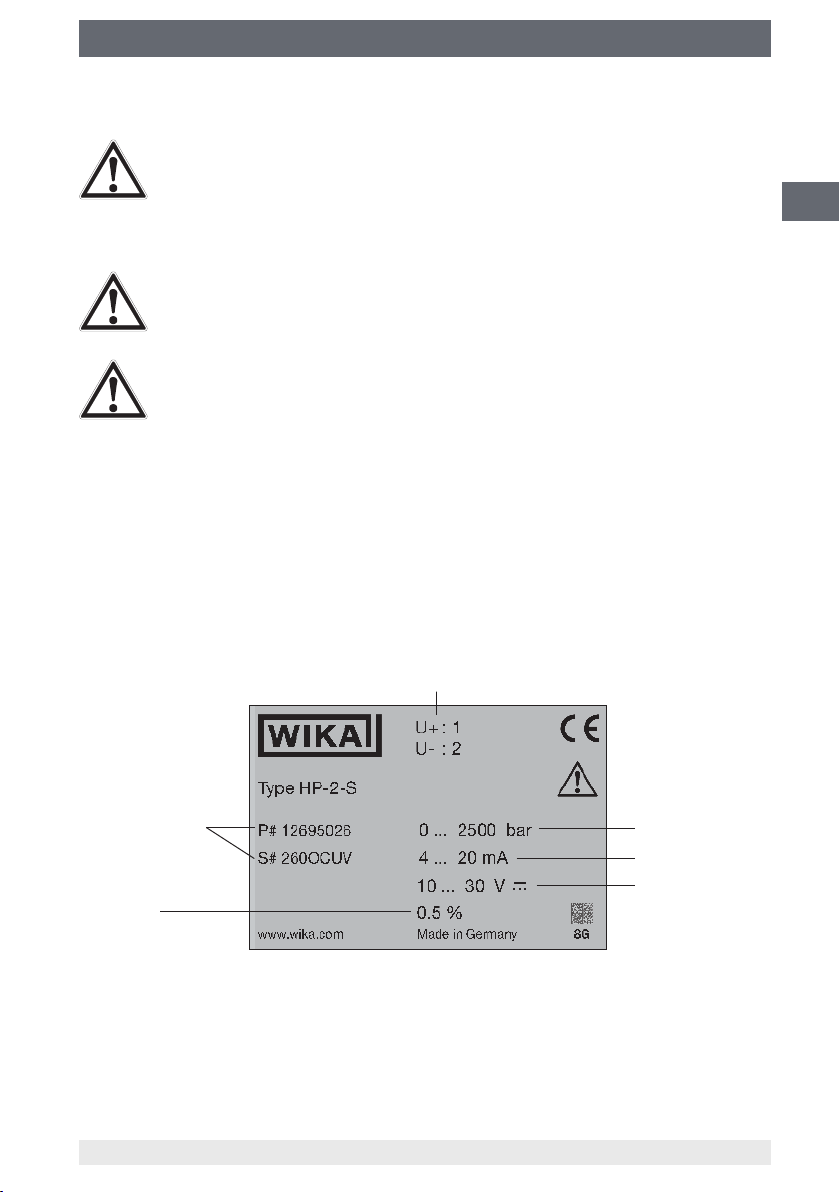
2.4 Labelling, safety marking
GB
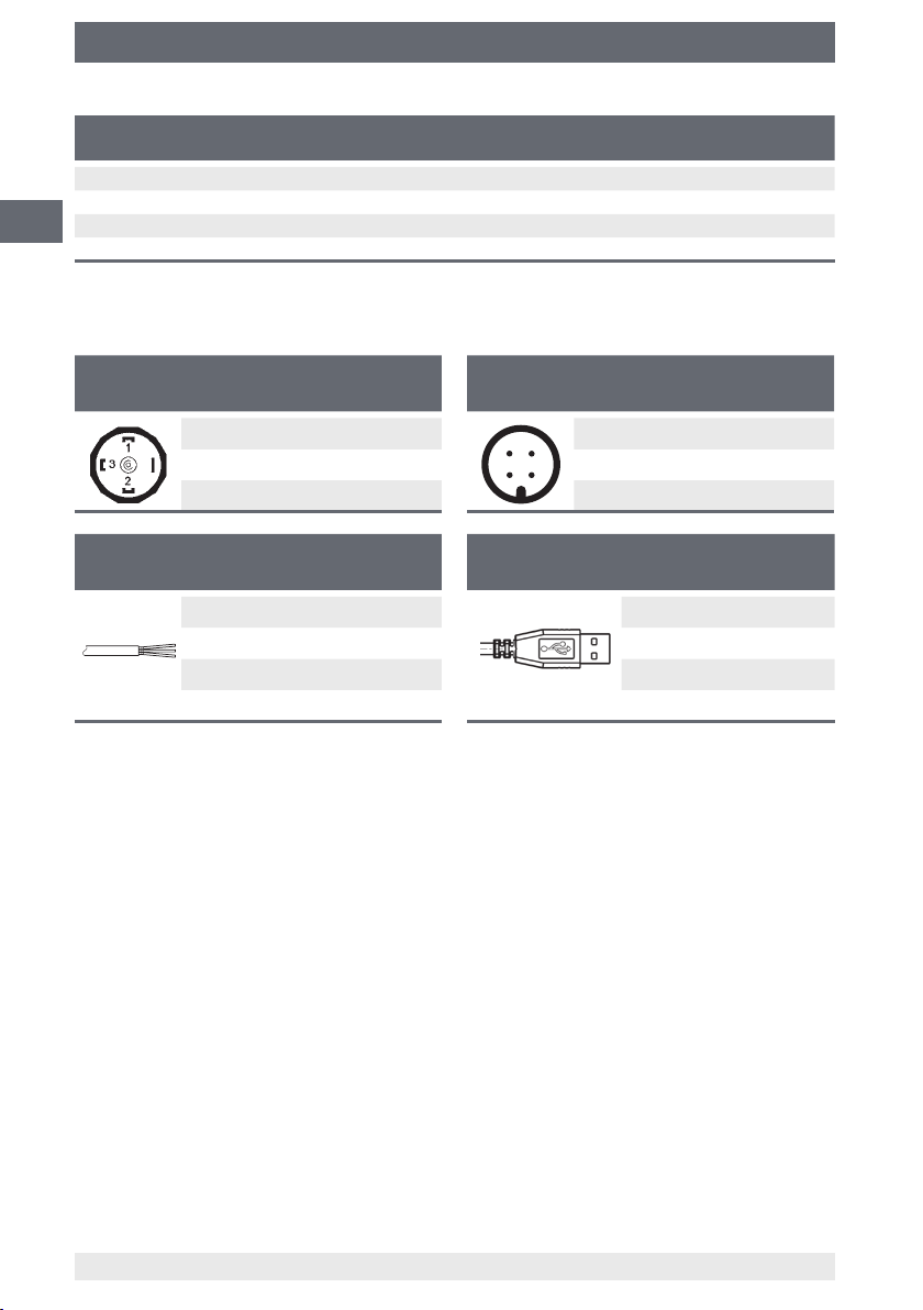
Product label
Pin assignment
P# Product no.
S# Serial no.
Accuracy
Measuring range
Output signal
Power supply
If the serial number becomes illegible due to mechanical damage or overpainting, traceability will no longer be possible.
11379180.03 09/2013 GB/D/F/E
WIKA operating instructions pressure transmitter, model HP-2
7
Page 8

2.Safety/3.Specications
Explanation of symbols
CE, Communauté Européenne
Instruments bearing this mark comply with the relevant European directives.
GB
3. Specications
WARNING!
When designing the system, please note that the values given (e.g. burst
pressure, overpressure limit) are dependent upon the material and thread
used.
Measuring ranges
Relative pressure
bar Measuring range 0 ... 1,600 0 ... 2,500 0 ... 4,000 0 ... 5,000
Overpressure limit 2,300 3,500 5,000 6,000
Burst pressure 4,000 6,000 8,000 10,000
Measuring range 0 ... 6,000 0 ... 7,000 0 ... 8,000 0 ... 10,000
Overpressure limit 7,000 8,000 10,000 11,000
Burst pressure 11,000 11,000 12,000 12,000
Measuring range 0 ... 12,000 0 ... 15,000
Overpressure limit 12,500 15,500
Burst pressure 14,000 16,000
psi Measuring range 0 ... 23,000 0 ... 36,000 0 ... 58,000 0 ... 72,000
Overpressure limit 33,300 50,500 72,500 87,000
Burst pressure 58,000 87,000 116,000 145,000
Measuring range 0 ... 87,000 0 ... 100,000 0 ... 115,000 0 ... 145,000
Overpressure limit 101,500 116,000 145,000 159,000
Burst pressure 159,500 159,500 174,000 174,000
Service life
On request, since the service life depends on the actual pressure prole.
Despite its excellent load cycle stability a permanent load cycle stability is only given
conditionally. This is due to the extreme loadings faced by the highly pressurised
materials. This applies particularly to dynamic applications. Accordingly, the pressureloaded parts of the HP-2 are considered as wear parts that are not covered by the
warranty.
8
WIKA operating instructions pressure transmitter, model HP-2
11379180.03 09/2013 GB/D/F/E
Page 9

3.Specications
Output signals
Signal type Signal
Current (2-wire) 4 ... 20 mA
Voltage (3-wire) DC 0 ... 5 V
USB USB 2.0
Power supply
The power supply depends on the selected output signal
■
4 ... 20 mA: DC 10 ... 30 V
■
DC 0 ... 5 V: DC 10 ... 30 V
■
DC 0 ... 10 V: DC 14 ... 30 V
■
USB 2.0: DC 5 V
LoadinΩ
■
Current output (2-wire): ≤ (power supply - 10 V) / 0.02 A
■
Voltage output (3-wire): > maximum output signal / 1 mA
Ingress protection (per IEC 60529)
■
Angular connector DIN 175301-803 A: IP 65
■
Circular connector M12 x 1 (4-pin): IP 67
■
USB connector type A: Instrument: IP 67, connector: IP 20
■
Cable outlet: IP 67
DC 0 ... 10 V
GB
The stated ingress protection only applies when plugged in using mating connectors
that have the appropriate ingress protection.
Permissible temperature ranges
■
Medium: 0 ... +80 °C
■
Ambient: -20 ... +80 °C
■
Storage: -40 ... +85 °C
CE conformity
■
EMC directive 2004/108/EC, EN 61326 emission (group 1, class B) and immunity
(industrial application)
With USB signal output and strong electromagnetic disturbances in the frequency
range 650 … 750 MHz, the accuracy can be inuenced by up to 1 %.
■
Pressure equipment directive 97/23/EC
RoHS conformity
Yes
For special model numbers, e.g. HP-20000, please note the specications stated on the
delivery note.
For further specications see WIKA data sheet PE 81.53 and the order documentation.
11379180.03 09/2013 GB/D/F/E
WIKA operating instructions pressure transmitter, model HP-2
9
Page 10

4. Design and function / 5. Transport, packaging and ...
4. Design and function
4.1 Short description
The prevailing pressure is measured at the sensor element through the deformation of
a diaphragm. By supplying power, this deformation of the diaphragm is converted into
GB
an electrical signal. The output signal from the pressure transmitter is amplied and
standardised.
4.2 Scope of delivery
Cross-check scope of delivery with delivery note.
5. Transport, packaging and storage
5.1 Transport
Check the pressure transmitter for any damage that may have been caused during
transportation.
Obvious damage must be reported immediately.
5.2 Packaging
Do not remove packaging until just before mounting.
Keep the packaging as it will provide optimum protection during transport (e.g. change
in installation site, sending for repair).
5.3 Storage
Permissible conditions at the place of storage:
see chapter 3 “Specications”
Store the pressure transmitter in its original packaging in a location that fulls the condi-
tions listed above.
WARNING!
Before storing the instrument (following operation), remove any residual
media. This is of particular importance if the medium is hazardous to health,
e.g. caustic, toxic, carcinogenic, radioactive, etc.
10
WIKA operating instructions pressure transmitter, model HP-2
11379180.03 09/2013 GB/D/F/E
Page 11
6. Commissioning, operation
6. Commissioning, operation
CAUTION!
Prior to commissioning, the pressure transmitter must be subjected to a
visual inspection.
Only use the pressure transmitter if it is in perfect condition with respect to
safety.
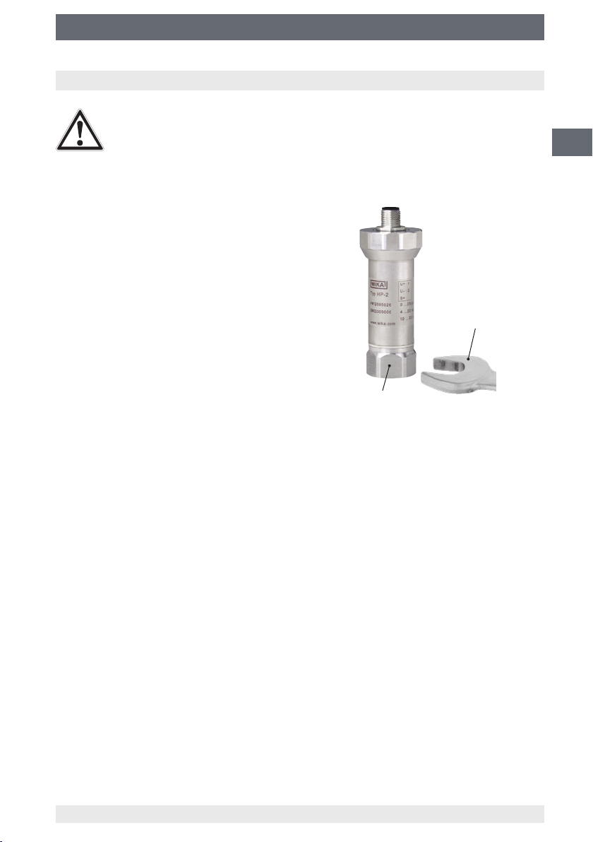
6.1 Mechanical mounting
■
The sealing faces at the instrument have to be
undamaged and clean.
■
When screwing the instrument in, the force
required to do this must not be applied through
the case, but only through the spanner ats
provided for this purpose and using a suitable
tool.
For the installation point, the valid values for
tightening torque and maximum pressure
should be taken from the high-pressure pipe
supplier's documentation.
GB
Open-ended spanner
(spanner width 27)
Spanner ats
■
When screwing in, do not cross the threads.
■
For information on tapped holes and welding sockets, see Technical information
IN 00.14 at www.wika.com.
6.2 Electrical mounting
■
The instrument must be grounded via the process connection.
■
Use the pressure transmitter with shielded cable, and ground the shield on at least
one end of the lead, if the lines are longer than 30 m (3- or 4-wire) or leave the building.
■
Select a cable diameter that matches the cable gland of the plug. Make sure that
the cable gland of the mounted plug has a tight t and that the seals are present and
undamaged. Tighten the threaded connection and check that the seal is correctly
seated, in order to ensure the ingress protection.
■
For cable outlets, make sure that no moisture enters at the cable end.
■
Observe the specications in accordance with chapter 3 “Specications”.
11379180.03 09/2013 GB/D/F/E
WIKA operating instructions pressure transmitter, model HP-2
11
Page 12
6. Commissioning, operation
Electrical connection Wire cross-section Cable∅ Cable
Angular connector DIN 175301-803 A max. 1.5 mm
Circular connector M12 x 1 (4-pin) - - -
GB
USB connector type A - - 2 m
Cable outlet 0.5 mm
2
2
(AWG 20) 6.8 mm 1.5 m
6 ... 8 mm -
Connection diagrams
For abbreviations see page 5
Angular connector DIN 175301-803 A
2-wire 3-wire
UB1 1
0V 2 2
S+ - 3
Cable outlet
2-wire 3-wire
UBbrown brown
0V green green
S+ - white
Circular connector M12 x 1 (4-pin)
2-wire 3-wire
4
1
0V 3 3
2
S+- 4
UB1 1
3
USB connector type A
lengths
+5V 1
GND 4
D+ 3
D- 2
12
WIKA operating instructions pressure transmitter, model HP-2
11379180.03 09/2013 GB/D/F/E
Page 13
6. Commissioning, operation
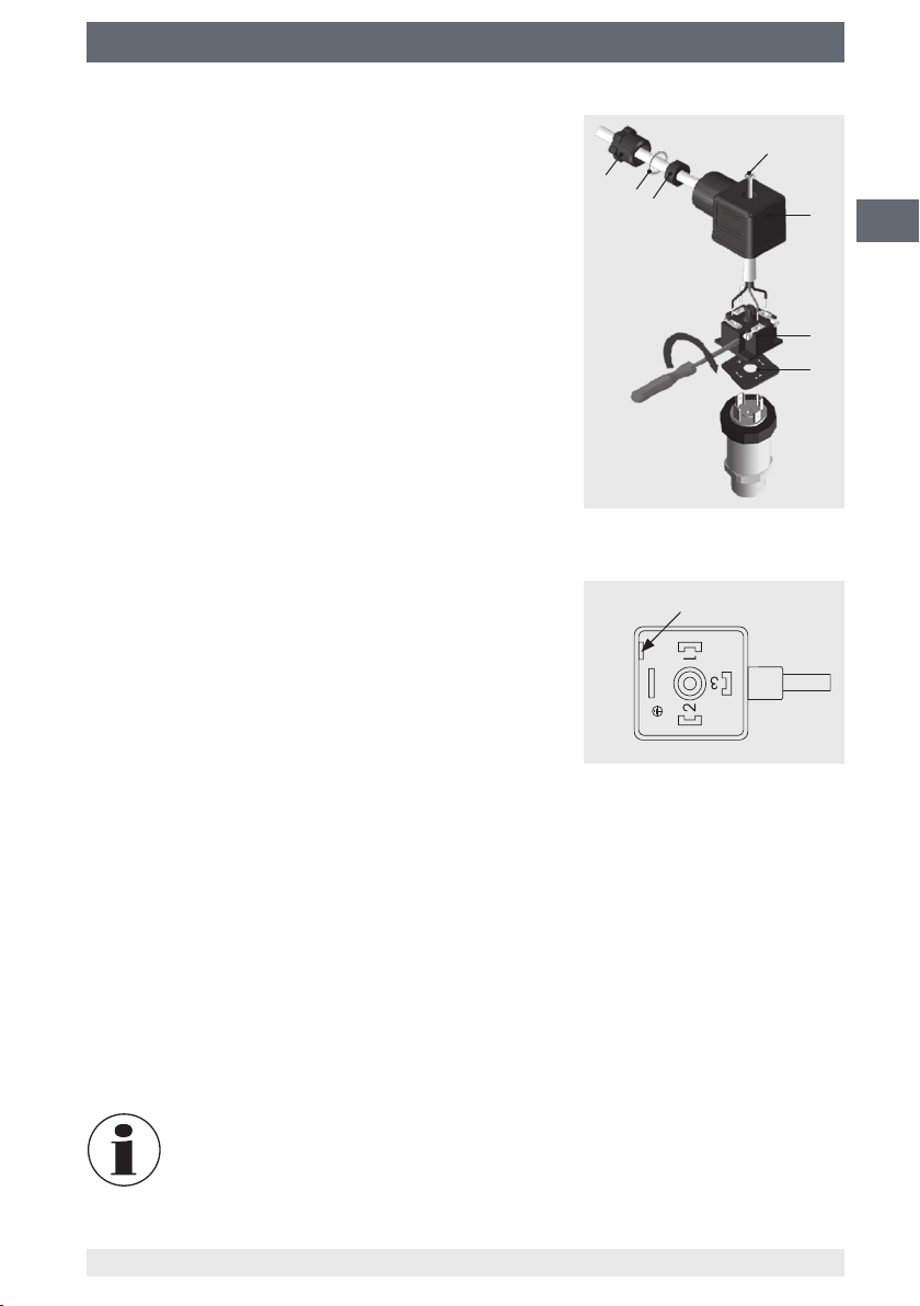
Fitting the DIN 175301-803 angular connector
1.
Loosen the screw .
2.
Loosen the cable gland .
3.
Pull the angled socket + from the instrument.
4.
Via the mounting hole , lever the terminal block
out of the case .
5. Pass the cable with the appropriate cable outer
diameter through the cable gland , ring ,
sealing and the case .
6. Connect the cable ends to the connection terminals on the terminal block in accordance with the
pin assignment (see “Connection diagrams” for the
pin assignment).
7.
Press the terminal block into the case .
8.
Tighten the cable gland around the cable.
Make sure that the cable gland and seal are not
damaged and that they are assembled correctly in
order to ensure ingress protection.
Mounting hole
GB
9.
Place the at, square gasket over the pressure
transmitter's connection pins.
10.
Slide the assembled angled socket + onto
the pressure transmitter's connection pins.
11.
Using the screw , screw the angled socket to the
pressure transmitter, hand-tight.
6.3 Commissioning of USB instruments
■
For installing the driver, administrator rights are required.
■
Connect the USB connector to a USB 2.0 port at your computer.
■
Install the driver via the InstallWizard of the product software.
■
For further operation the P-3x data logger software is available (for details see
instruction manual P-3x data logger).
■
Details on the interface protocol or the DLL (Dynamic Link Library) are available on
the software CD and in the download section at www.wika.com.
For the model HP-2, model P-30 software must be used. All les and
documents are available for download at www.wika.com.
11379180.03 09/2013 GB/D/F/E
WIKA operating instructions pressure transmitter, model HP-2
13
Page 14
7. Adjustment of zero point and span
7. Adjustment of zero point and span
Only adjust the span-setting potentiometer if calibration equipment is avail-
GB
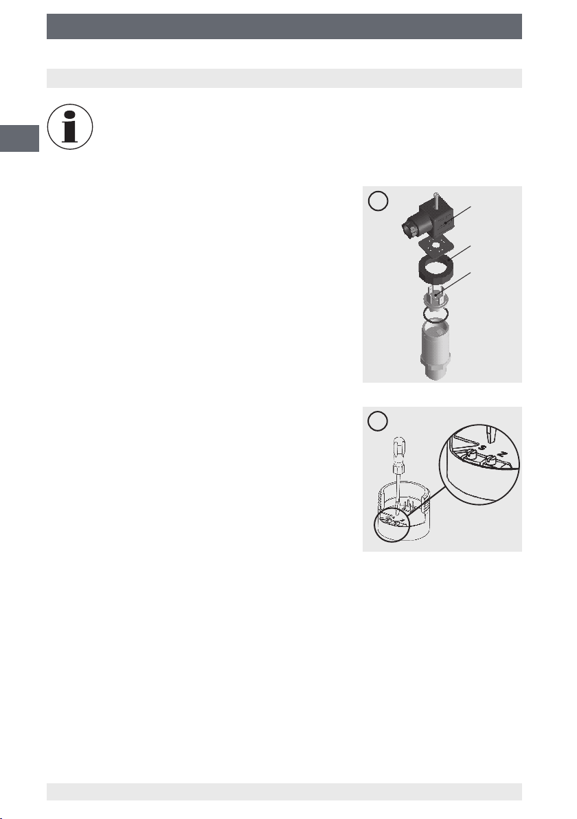
7.1 Preparation(gureA)
To gain access to the potentiometers, open the instrument as follows:
■
Disconnect the electrical connection from the
instrument.
■
Remove the clamping nut .
■
Carefully pull the instrument connector from the
instrument.
■
Connect the instrument connector to the power
supply and a display unit (e.g. ammeter, voltmeter)
according to the connection diagram.
7.2 Adjustmentofzeropoint(gureB)
■
Go to the start of the measuring range.
■
Using potentiometer “Z”, adjust the minimum output
signal (e.g. 4 mA).
7.3 Settingthespan(gureB)
■
Go to the end of the measuring range.
■
Using potentiometer “S”, adjust the maximum output
signal (e.g. 20 mA).
■
Check the zero point and if there is any deviation,
re-adjust it.
■
Repeat the procedure until the zero point and the
span are set correctly.
able which has at least three times the accuracy of the pressure transmitter.
A
B
7.4 Finishtheadjustment(gureA)
■
Disconnect the instrument connector from the power supply and the display unit.
■
Carefully push the instrument connector onto the instrument, without damaging the
wires or the seals. The seals must be clean and undamaged in order to guarantee the
given ingress protection.
■
Tighten the clamping nut .
After the adjustment, check that the system is functioning correctly.
Recommended recalibration cycle: Half-yearly
14
WIKA operating instructions pressure transmitter, model HP-2
11379180.03 09/2013 GB/D/F/E
Page 15
8. Spare part kit
8. Spare part kit
The spare part kit is used for the exchange of process connections and the bae
plate of the models HP-2-D and HP-2-E. It is not compatible with the standard version,
model HP-2-S.
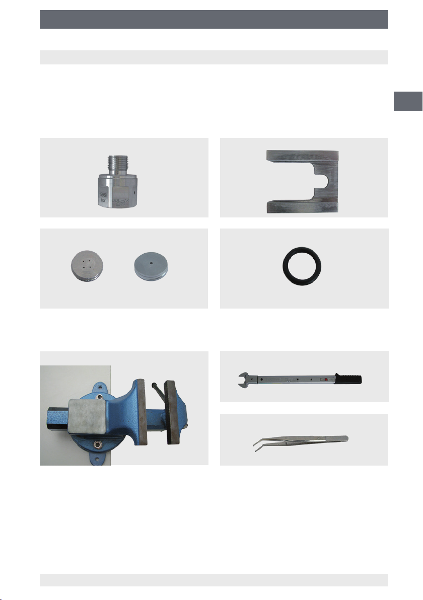
8.1 Contents of the spare part kit
Clamping jawExchangeable process connection
BaeplateforDIPSorEPC O-ring
DIPS EPC
GB
8.2 Tools required
Vice
11379180.03 09/2013 GB/D/F/E
WIKA operating instructions pressure transmitter, model HP-2
Torque spanner
Tweezers
15
Page 16
8. Spare part kit
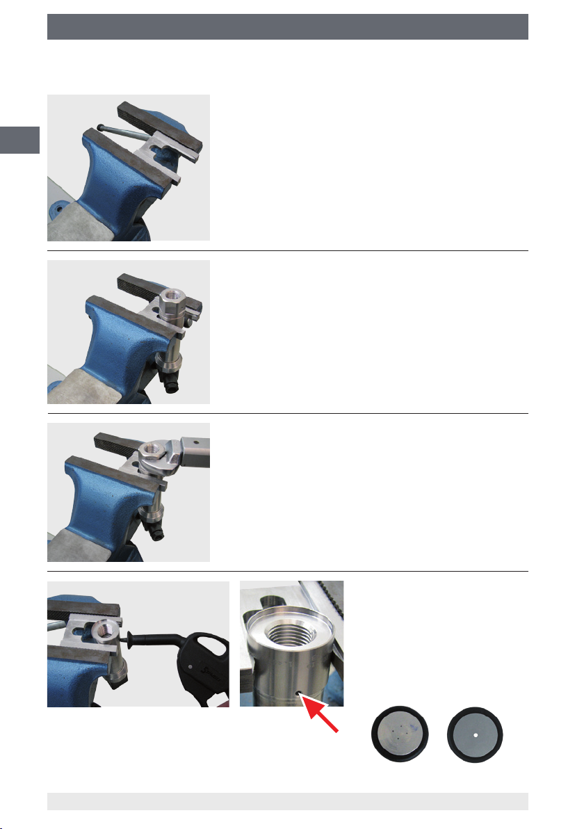
8.3 Mounting
GB
Secure the clamping jaw in the vice as shown, so that
this cannot come loose.
Slide the pressure transmitter between the clamping
jaw, using the groove milled into the process connection.
Loosen the process connection using the torque
spanner.
16
Dry the bae plate incl. the
O-ring using compressed air.
For access, there is a bore
on the process connection.
Bae plate
DIPS EPC
11379180.03 09/2013 GB/D/F/E
WIKA operating instructions pressure transmitter, model HP-2
Page 17
8. Spare part kit
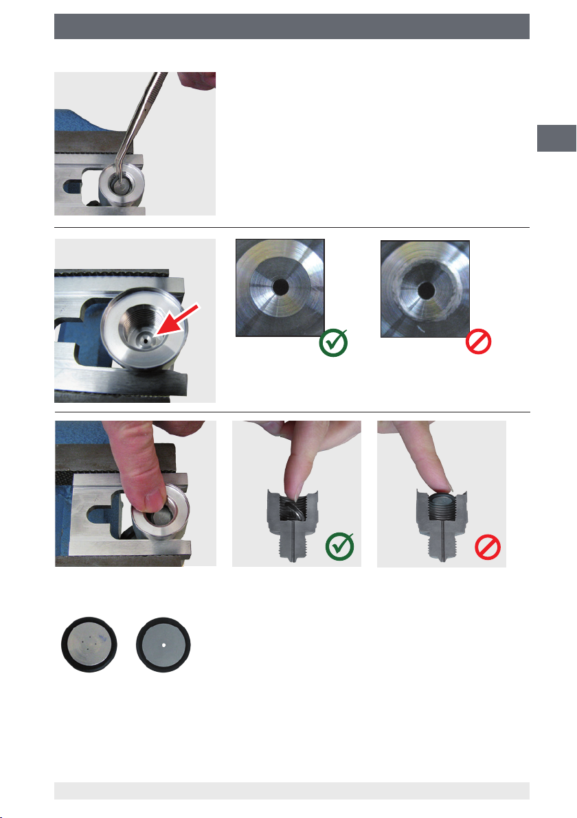
Remove the dry bae plate incl. the O-ring using the
tweezers.
GB
Check the sealing cone for damage.
If the sealing cone is damaged, the entire instrument
must be replaced.
Insert the new bae plate with O-ring at an angle, and press down, taking care not to
damage the surface of the bae plate and the O-ring.
DIPS EPC
11379180.03 09/2013 GB/D/F/E
WIKA operating instructions pressure transmitter, model HP-2
17
Page 18
8. Spare part kit / 9. Maintenance and cleaning
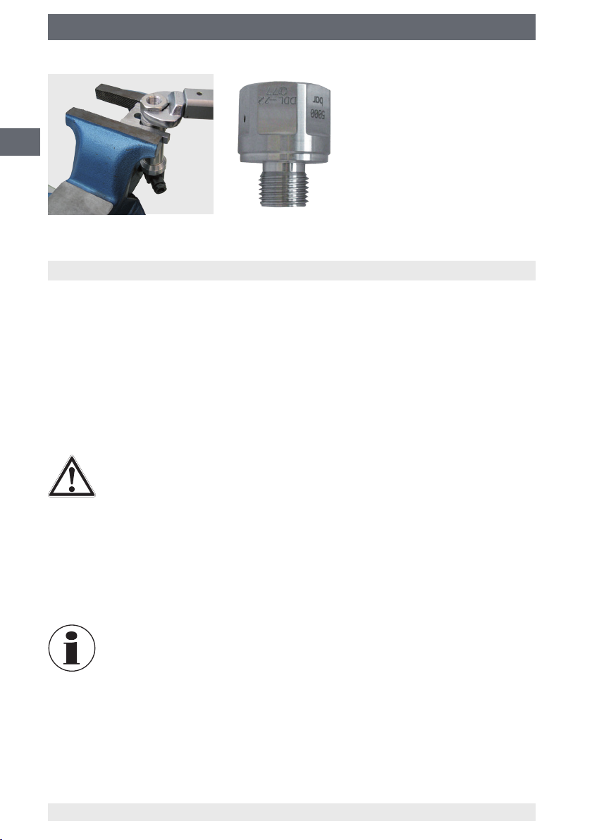
Tighten the exchangeable
process connection using the
torque spanner.
GB
On the torque spanner, set
the tightening torque to
130 Nm.
9. Maintenance and cleaning
9.1 Maintenance
Repairs must only be carried out by the manufacturer.
When a leak is suspected, as a result of hairline cracks in the process connection, as
described in chapter 8 “Spare part kit”, replace it.
For the order number for the spare part kit see chapter 12 “Accessories”
9.2 Cleaning
CAUTION!
■
Before cleaning, correctly disconnect the pressure transmitter from the
pressure supply, switch it o and disconnect it from the voltage supply.
■
Clean the instrument with a moist cloth.
■
Electrical connections must not come into contact with moisture.
■
Wash or clean the dismounted instrument before returning it, in order to
protect persons and the environment from exposure to residual media.
■
Residual media in the dismounted pressure transmitter can result in a risk
to persons, the environment and equipment. Take sucient precautionary
measures.
18
For information on returning the instrument see chapter 11.2 “Return”.
11379180.03 09/2013 GB/D/F/E
WIKA operating instructions pressure transmitter, model HP-2
Page 19
10. Faults
10. Faults
In the event of any faults, rst check whether the pressure transmitter is mounted
correctly, mechanically and electrically.
Faults Causes Measures
No output signal Cable break Replace connecting cable
No/wrong power supply Correct the power supply
No/wrong output signal Wiring error Rectify the wiring in accordance
Constant output signal upon
change in pressure
Deviating output signal Zero point change through
Signal span too high Pressure spikes, cavitations Use instrument with cavitation and
Signal span too small Wrong power supply Rectify the power supply
Signal span varies EMC interference sources in the
Leakage at the process connection Hairline crack in the pressure port Consult with manufacturer, if
Wrong power supply Replace instrument
dynamic pressure
environment
Instrument not grounded Ground the instrument
Strongly varying pressure of the
medium
with the connection diagram
Re-adjust zero point
pressure-spike protection
Shield the instrument and cables,
remove source of interference
Damping (consulting by the
manufacturer)
required, replace instrument.
GB
If complaint is unjustied, the handling costs will be charged.
CAUTION!
If faults cannot be eliminated by means of the measures listed above, shut
down the pressure transmitter immediately, and ensure that pressure and/or
signal are no longer present, and secure the instrument from being put back
into operation inadvertently.
In this case, contact the manufacturer.
If a return is needed, please follow the instructions given in chapter
11.2 “Return”.
11379180.03 09/2013 GB/D/F/E
WIKA operating instructions pressure transmitter, model HP-2
19
Page 20
11. Dismounting, return and disposal
11. Dismounting, return and disposal
WARNING!
GB
11.1 Dismounting
Only disconnect the pressure gauge once the system has been depressurised!
11.2 Return
Residual media in the dismounted pressure transmitter can result in a risk to
persons, the environment and equipment.
Take sucient precautionary measures.
WARNING!
Risk of burns!
Let the instrument cool down suciently before dismounting it!
During dismounting there is a risk of dangerously hot pressure media
escaping.
WARNING!
Strictly observe the following when shipping the instrument:
All instruments delivered to WIKA must be free from any kind of hazardous
substances (acids, bases, solutions, etc.).
When returning the instrument, use the original packaging or a suitable transport
package.
Information on returns can be found under the heading “Service” on our local
website.
11.3 Disposal
Incorrect disposal can put the environment at risk.
Dispose of instrument components and packaging materials in an environmentally
compatible way and in accordance with the country-specic waste disposal regulations.
20
WIKA operating instructions pressure transmitter, model HP-2
11379180.03 09/2013 GB/D/F/E
Page 21

12. Accessories
12. Accessories
Accessories and spare parts
Mating connector
Designation Order number
without cable with 2 m cable with 5 m cable
Angular connector DIN 175301-803 A
■
with cable gland, metric 11427567 11225793 11250186
■
with cable gland, conduit 11022485 - -
Circular connector M12 x 1, 4-pin
■
straight 2421262 11250780 11250259
■
angled 2421270 11250798 11250232
Sealings for mating connectors
Designation Order number
Angular connector DIN 175301-803 A 1576240
Spare part kit for models HP-2-D and HP-2-E
Consisting of a replacement connection thread, replacement sealing disc and a mounting aid.
Spare part kit suitable for the following process connections:
Process connection Order number
Model HP-2-D Model HP-2-E
M16 x 1.5 female 14039895 14050403
M20 x 1.5 female 13319923 14050404
Software
The full software is available to download as freeware from the following path.
www.wika.com / Download / Software / Electronic pressure measurement
GB
11379180.03 09/2013 GB/D/F/E
WIKA operating instructions pressure transmitter, model HP-2
21
Page 22
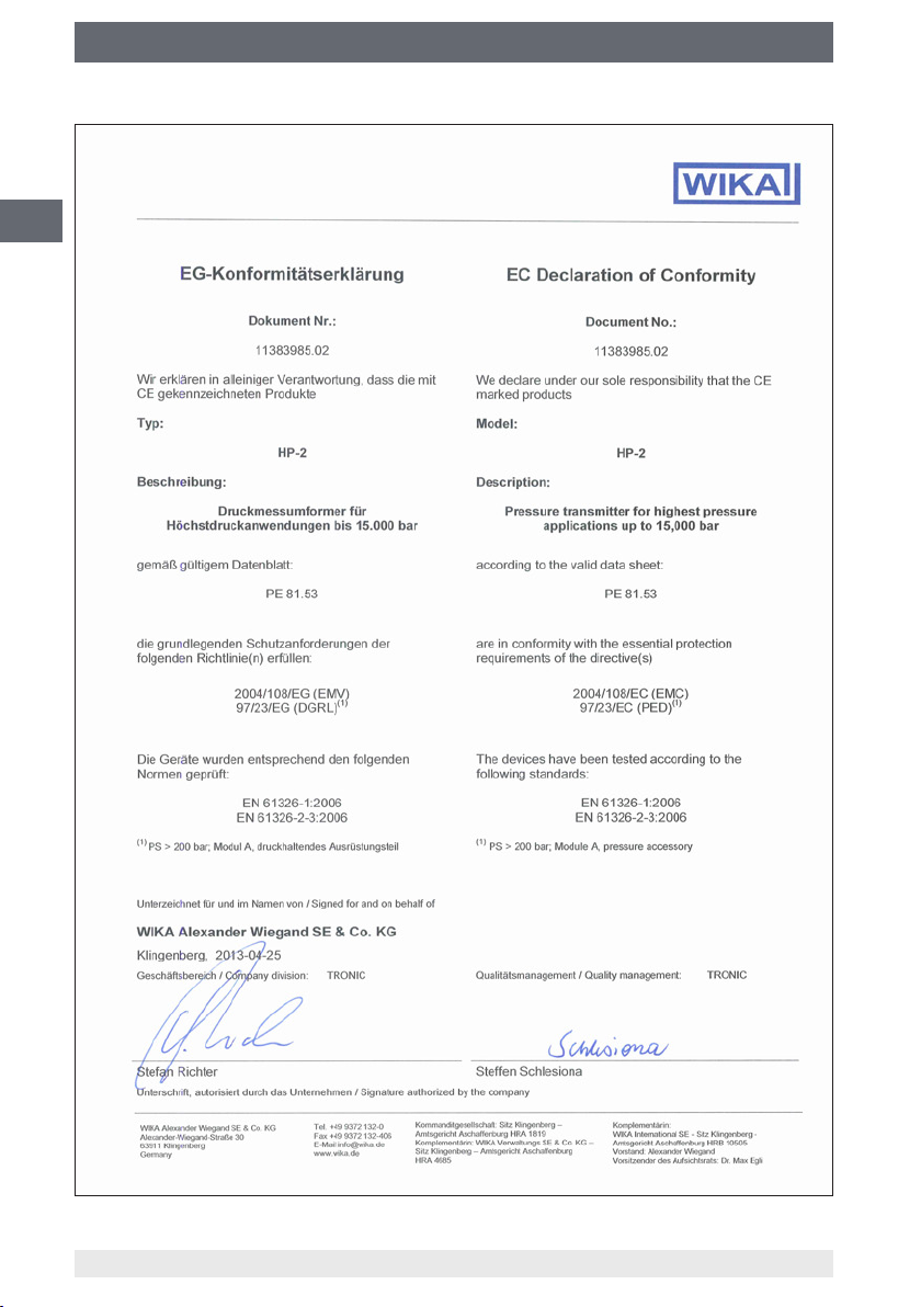
Appendix 1: Declaration of conformity for model HP-2
GB
22
WIKA operating instructions pressure transmitter, model HP-2
11379180.03 09/2013 GB/D/F/E
Page 23

Inhalt
Inhalt
1. Allgemeines 24
2. Sicherheit 25
3. Technische Daten 28
4. Aufbau und Funktion 30
5. Transport, Verpackung und Lagerung 30
6. Inbetriebnahme, Betrieb 31
7. Einstellung Nullpunkt und Spanne 34
8. Ersatzteilkit 35
9. Wartung und Reinigung 38
10. Störungen 39
D
11. Demontage, Rücksendung und Entsorgung 40
12. Zubehör 41
Anlage 1: Konformitätserklärung Typ HP-2 42
Konformitätserklärungen nden Sie online unter www.wika.de
11379180.03 09/2013 GB/D/F/E
23WIKA Betriebsanleitung Druckmessumformer, Typ HP-2
Page 24

1. Allgemeines
1. Allgemeines
■
Der in der Betriebsanleitung beschriebene Druckmessumformer wird nach dem
aktuellen Stand der Technik konstruiert und gefertigt.
Alle Komponenten unterliegen während der Fertigung strengen Qualitäts- und
Umweltkriterien. Unsere Managementsysteme sind nach ISO 9001 und ISO 14001
zertiziert.
D
■
Diese Betriebsanleitung gibt wichtige Hinweise zum Umgang mit dem Gerät. Voraussetzung für sicheres Arbeiten ist die Einhaltung aller angegebenen Sicherheitshinweise und Handlungsanweisungen.
■
Die für den Einsatzbereich des Gerätes geltenden örtlichen Unfallverhütungsvorschriften und allgemeinen Sicherheitsbestimmungen einhalten.
■
Die Betriebsanleitung ist Produktbestandteil und muss in unmittelbarer Nähe des
Gerätes für das Fachpersonal jederzeit zugänglich aufbewahrt werden.
■
Das Fachpersonal muss die Betriebsanleitung vor Beginn aller Arbeiten sorgfältig
durchgelesen und verstanden haben.
■
Die Haftung des Herstellers erlischt bei Schäden durch bestimmungswidrige Verwen-
dung, Nichtbeachten dieser Betriebsanleitung, Einsatz ungenügend qualizierten
Fachpersonals sowie eigenmächtiger Veränderung am Gerät.
■
Es gelten die allgemeinen Geschäftsbedingungen in den Verkaufsunterlagen.
■
Technische Änderungen vorbehalten.
■
Weitere Informationen:
- Internet-Adresse: www.wika.de / www.wika.com
- zugehöriges Datenblatt: PE 81.53
- Anwendungsberater:
Tel.: +49 9372 132-8976
Fax: +49 9372 132-8008976
support-tronic@wika.de
24 WIKA Betriebsanleitung Druckmessumformer, Typ HP-2
11379180.03 09/2013 GB/D/F/E
Page 25
1. Allgemeines / 2. Sicherheit
Symbolerklärung
WARNUNG!
… weist auf eine möglicherweise gefährliche Situation hin, die zum Tod oder
zu schweren Verletzungen führen kann, wenn sie nicht gemieden wird.
VORSICHT!
… weist auf eine möglicherweise gefährliche Situation hin, die zu geringfügigen oder leichten Verletzungen bzw. Sach- und Umweltschäden führen
kann, wenn sie nicht gemieden wird.
Information
… hebt nützliche Tipps und Empfehlungen sowie Informationen für einen
ezienten und störungsfreien Betrieb hervor.
WARNUNG!
… weist auf eine möglicherweise gefährliche Situation hin, die durch heiße
Oberächen oder Flüssigkeiten zu Verbrennungen führen kann, wenn sie
nicht gemieden wird.
Abkürzungen
2-Leiter Die zwei Anschlussleitungen dienen zur Spannungsversorgung.
Der Speisestrom ist das Messsignal.
3-Leiter Zwei Anschlussleitungen dienen zur Spannungsversorgung.
Eine Anschlussleitung dient für das Messsignal.
U
, +5V Positive Hilfsenergie
B
0V, GND Bezugspotential
S
+
,D
D
+
Positiver Messanschluss
Datenleitung USB 2.0
-
2. Sicherheit
D
WARNUNG!
Vor Montage, Inbetriebnahme und Betrieb sicherstellen, dass der richtige
Druckmessumformer hinsichtlich Messbereich, Ausführung und spezischen Messbedingungen ausgewählt wurde.
Der Betreiber muss die Verträglichkeit des Fluides mit dem eingesetzen
Werksto sicherstellen. Bei Medium Wassersto den Hersteller kontaktieren.
Bei Nichtbeachten können schwere Körperverletzungen und/oder
Sachschäden auftreten.
11379180.03 09/2013 GB/D/F/E
25WIKA Betriebsanleitung Druckmessumformer, Typ HP-2
Page 26
2. Sicherheit
WARNUNG!
■
Anschlüsse nur im drucklosen Zustand önen.
■
Betriebsparameter gemäß Kapitel 3 „Technische Daten“ beachten.
■
Druckmessumformer immer innerhalb der Überlast-Druckgrenze betreiben.
D
Weitere wichtige Sicherheitshinweise benden sich in den einzelnen
Kapiteln dieser Betriebsanleitung.
2.1 Bestimmungsgemäße Verwendung
Der Druckmessumformer dient zum Umwandeln von Druck in ein elektrisches Signal.
Das Gerät ist ausschließlich für den hier beschriebenen bestimmungsgemäßen Verwendungszweck konzipiert und konstruiert und darf nur dementsprechend verwendet werden.
Die technischen Spezikationen in dieser Betriebsanleitung sind einzuhalten. Eine
unsachgemäße Handhabung oder ein Betreiben des Gerätes außerhalb der techni-
schen Spezikationen macht die sofortige Stilllegung und Überprüfung durch einen
autorisierten WIKA-Servicemitarbeiter erforderlich.
Ansprüche jeglicher Art aufgrund von nicht bestimmungsgemäßer Verwendung sind
ausgeschlossen.
2.2 Personalqualikation
WARNUNG!
VerletzungsgefahrbeiunzureichenderQualikation!
Unsachgemäßer Umgang kann zu erheblichen Personen- und Sachschäden führen.
Die in dieser Betriebsanleitung beschriebenen Tätigkeiten nur durch
Fachpersonal nachfolgend beschriebener Qualikation durchführen lassen.
Fachpersonal
Das Fachpersonal ist aufgrund seiner fachlichen Ausbildung, seiner Kenntnisse der
Mess- und Regelungstechnik und seiner Erfahrungen sowie Kenntnis der landesspezi-
schen Vorschriften, geltenden Normen und Richtlinien in der Lage, die beschriebenen
Arbeiten auszuführen und mögliche Gefahren selbstständig zu erkennen.
Spezielle Einsatzbedingungen verlangen weiteres entsprechendes Wissen, z. B. über
aggressive Medien.
26 WIKA Betriebsanleitung Druckmessumformer, Typ HP-2
11379180.03 09/2013 GB/D/F/E
Page 27

2. Sicherheit
2.3 Besondere Gefahren
WARNUNG!
Bei gefährlichen Messstoen wie z. B. Sauersto, Acetylen, brennbaren
oder giftigen Stoen, sowie bei Kälteanlagen, Kompressoren etc. müssen
über die gesamten allgemeinen Regeln hinaus die einschlägigen Vorschriften beachtet werden.
WARNUNG!
Es sind keine Anlagenzustände gestattet, die zur Bildung von atomarem
Wassersto im Anschlusskanal des Druckmessumformers führen können.
WARNUNG!
Messstoreste im ausgebauten Druckmessumformer können zur Gefährdung von Personen, Umwelt und Einrichtung führen.
Ausreichende Vorsichtsmaßnahmen ergreifen.
Dieses Gerät nicht in Sicherheits- oder in Not-Aus-Einrichtungen benutzen.
Fehlerhafte Anwendungen des Gerätes können zu Verletzungen führen
Am Gerät können im Fehlerfall aggressive Medien mit extremer Temperatur
und unter hohem Druck oder Vakuum anliegen.
D
.
2.4 Beschilderung, Sicherheitskennzeichnungen
Typenschild
Anschlussbelegung
P# Erzeugnis-Nr.
S# Serien-Nr.
Genauigkeit
Messbereich
Ausgangssignal
Hilfsenergie
Wird die Seriennummer durch mechanische Beschädigung oder Übermalen unleserlich,
ist eine Rückverfolgbarkeit nicht mehr möglich.
11379180.03 09/2013 GB/D/F/E
27WIKA Betriebsanleitung Druckmessumformer, Typ HP-2
Page 28

2. Sicherheit / 3. Technische Daten
Symbolerklärung
CE, Communauté Européenne
Geräte mit dieser Kennzeichnung stimmen überein mit den zutreenden
europäischen Richtlinien.
D
3. Technische Daten
WARNUNG!
Bei der Auslegung der Anlage ist zu beachten, dass die angegebenen Werte
(z. B. Berstdruck, Überlast-Druckgrenze) in Abhängigkeit vom verwendeten
Material und Gewinde gelten.
Messbereiche
Relativdruck
bar Messbereich 0 ... 1.600 0 ... 2.500 0 ... 4.000 0 ... 5.000
Überlast-Druckgrenze 2.300 3.500 5.000 6.000
Berstdruck 4.000 6.000 8.000 10.000
Messbereich 0 ... 6.000 0 ... 7.000 0 ... 8.000 0 ... 10.000
Überlast-Druckgrenze 7.000 8.000 10.000 11.000
Berstdruck 11.000 11.000 12.000 12.000
Messbereich 0 ... 12.000 0 ... 15.000
Überlast-Druckgrenze 12.500 15.500
Berstdruck 14.000 16.000
psi Messbereich 0 ... 23.000 0 ... 36.000 0 ... 58.000 0 ... 72.000
Überlast-Druckgrenze 33.300 50.500 72.500 87.000
Berstdruck 58.000 87.000 116.000 145.000
Messbereich 0 ... 87.000 0 ... 100.000 0 ... 115.000 0 ... 145.000
Überlast-Druckgrenze 101.500 116.000 145.000 159.000
Berstdruck 159.500 159.500 174.000 174.000
Lebensdauer
Auf Anfrage, da die Lebensdauer vom tatsächlichen Druckverlauf abhängt.
Trotz seiner hervorragenden Lastwechselfestigkeit ist eine Dauerlastwechselfestigkeit
nur bedingt gegeben. Grund dafür sind die extremen Belastungen, denen die
hochdruckbeaufschlagten Materialien ausgesetzt sind. Dies gilt insbesondere für
dynamische Anwendungen. Dementsprechend handelt es sich bei den druckbelasteten
Teilen des HP-2 um Verschleißteile, die nicht unter die Gewährleistung fallen.
28 WIKA Betriebsanleitung Druckmessumformer, Typ HP-2
11379180.03 09/2013 GB/D/F/E
Page 29

3. Technische Daten
Ausgangssignale
Signalart Signal
Strom (2-Leiter) 4 ... 20 mA
Spannung (3-Leiter) DC 0 ... 5 V
USB USB 2.0
DC 0 ... 10 V
Hilfsenergie
Die Hilfsenergie ist abhängig vom gewählten Ausgangssignal
■
4 ... 20 mA: DC 10 ... 30 V
■
DC 0 ... 5 V: DC 10 ... 30 V
■
DC 0 ... 10 V: DC 14 ... 30 V
■
USB 2.0: DC 5 V
BürdeinΩ
■
Stromausgang (2-Leiter): ≤ (Hilfsenergie - 10 V) / 0,02 A
■
Spannungsausgang (3-Leiter): > maximales Ausgangssignal / 1 mA
Schutzarten (nach IEC 60529)
■
Winkelstecker DIN 175301-803 A: IP 65
■
Rundstecker M12 x 1 (4-polig): IP 67
■
USB-Stecker Typ A: Gerät: IP 67, Stecker: IP 20
■
Kabelausgang: IP 67
Die angegebenen Schutzarten gelten nur im gesteckten Zustand mit Gegensteckern
entsprechender Schutzart.
Zulässige Temperaturbereiche
■
Medium: 0 ... +80 °C
■
Umgebung: -20 ... +80 °C
■
Lagerung: -40 ... +85 °C
D
CE-Konformität
■
EMV-Richtline
2004/108/EG
EN 61326 Emission (Gruppe 1, Klasse B)
und Störfestigkeit (industrieller Bereich)
Bei Signalausgang USB und starken elektromagnetischen Störungen im Frequenz-
bereich 650 … 750 MHz können Beeinussungen der Genauigkeit bis 1 % auftreten.
■
Druckgeräterichtlinie 97/23/EG
RoHS-Konformität
Ja
Bei Sondertypennummer, z. B. HP-20000 Spezikationen gemäß Lieferschein beachten.
Weitere technische Daten siehe WIKA-Datenblatt PE 81.53 und Bestellunterlagen.
11379180.03 09/2013 GB/D/F/E
29WIKA Betriebsanleitung Druckmessumformer, Typ HP-2
Page 30

4. Aufbau und Funktion / 5. Transport, Verpackung und ...
4. Aufbau und Funktion
4.1 Kurzbeschreibung
Der anstehende Druck wird mittels Membranverformung am Sensorelement gemessen.
Unter Zuführung von Hilfsenergie wird diese Membranverformung in ein elektrisches
Signal umgewandelt. Das vom Druckmessumformer ausgegebene Signal ist verstärkt
und standardisiert.
D
4.2 Lieferumfang
Lieferumfang mit dem Lieferschein abgleichen.
5. Transport, Verpackung und Lagerung
5.1 Transport
Den Druckmessumformer auf eventuell vorhandene Transportschäden untersuchen.
Oensichtliche Schäden unverzüglich mitteilen.
5.2 Verpackung
Verpackung erst unmittelbar vor der Montage entfernen.
Die Verpackung aufbewahren, denn diese bietet bei einem Transport einen optimalen
Schutz (z. B. wechselnder Einbauort, Reparatursendung).
5.3 Lagerung
Zulässige Bedingungen am Lagerort:
siehe Kapitel 3 „Technische Daten“
Den Druckmessumformer in der Originalverpackung an einem Ort lagern, der die oben
gelisteten Bedingungen erfüllt.
WARNUNG!
Vor der Einlagerung des Gerätes (nach Betrieb) alle anhaftenden Messstoreste entfernen. Dies ist besonders wichtig, wenn der Messsto gesund-
heitsgefährdend ist, wie z. B. ätzend, giftig, krebserregend, radioaktiv, usw.
30 WIKA Betriebsanleitung Druckmessumformer, Typ HP-2
11379180.03 09/2013 GB/D/F/E
Page 31

6. Inbetriebnahme, Betrieb
6. Inbetriebnahme, Betrieb
VORSICHT!
Vor der Inbetriebnahme den Druckmessumformer optisch prüfen.
Den Druckmessumformer nur in sicherheitstechnisch einwandfreiem
Zustand einsetzen.
6.1 Mechanische Montage
■
Dichtächen am Gerät und an der Messstelle
müssen unbeschädigt und frei von Verschmutzungen sein.
■
Beim Einschrauben des Gerätes darf die dazu
erforderliche Kraft nicht über das Gehäuse
aufgebracht werden, sondern nur mit geeignetem
Werkzeug über die dafür vorgesehene Schlüssel-
äche.
Die für die Montagestelle gültigen Werte für
Anzugsmoment und Maximaldruck sind aus den
Unterlagen des Hochdruckrohr-Lieferanten zu
entnehmen.
D
Maulschlüssel
(Schlüsselweite 27)
Schlüsseläche
■
Beim Einschrauben die Gewindegänge nicht verkanten.
■
Angaben zu Einschraublöchern und Einschweißstutzen siehe Technische Information
IN 00.14 unter www.wika.de.
6.2 Elektrische Montage
■
Das Gerät über den Prozessanschluss erden.
■
Den Druckmessumformer mit geschirmter Leitung betreiben und den Schirm auf
mindestens einer Leitungsseite erden, wenn die Leitungen länger als 30 m (3- bzw.
4-Leiter) sind oder das Gebäude verlassen.
■
Den Kabeldurchmesser passend zur Kabeldurchführung des Steckers wählen.
Darauf achten, dass die Kabelverschraubung des montierten Steckers korrekt sitzt
und dass die Dichtungen vorhanden und nicht beschädigt sind. Die Verschraubung
festziehen und den korrekten Sitz der Dichtungen überprüfen, um die Schutzart zu
gewährleisten.
■
Beim Kabelausgang sicherstellen, dass am Ende des Kabels keine Feuchtigkeit
eintritt.
■
Technische Daten gemäß Kapitel 3 „Technische Daten“ einhalten.
11379180.03 09/2013 GB/D/F/E
31WIKA Betriebsanleitung Druckmessumformer, Typ HP-2
Page 32

6. Inbetriebnahme, Betrieb
Elektrischer Anschluss Aderquerschnitt Kabel-∅ Kabellängen
Winkelstecker DIN 175301-803 A max. 1,5 mm
Rundstecker M12 x 1 (4-polig) - - USB-Stecker Typ A - - 2 m
Kabelausgang 0,5 mm
Anschlussschemen
D
Abkürzungen siehe Seite 25
2
2
(AWG 20) 6,8 mm 1,5 m
6 ... 8 mm -
Winkelstecker DIN 175301-803 A
2-Leiter 3-Leiter
UB1 1
0V 2 2
S+ - 3
Kabelausgang
2-Leiter 3-Leiter
UBbraun braun
0V grün grün
S+ - weiß
Rundstecker M12 x 1 (4-polig)
2-Leiter 3-Leiter
4
1
0V 3 3
2
S+- 4
UB1 1
3
USB-Stecker Typ A
+5V 1
GND 4
D+ 3
D- 2
32 WIKA Betriebsanleitung Druckmessumformer, Typ HP-2
11379180.03 09/2013 GB/D/F/E
Page 33

6. Inbetriebnahme, Betrieb
Montage des Winkelsteckers DIN 175301-803
1.
Die Schraube lösen.
2.
Die Kabelverschraubung lösen.
3.
Die Winkeldose + vom Gerät abziehen.
4.
Über die Montageönung den Klemmblock
aus dem Gehäuse hebeln.
D
5. Das Kabel mit passendem Leitungsaußendurchmesser durch Kabelverschraubung , Ring ,
Dichtung und das Gehäuse schieben.
6. Die Kabelenden entsprechend der Belegung in den
Anschlussklemmen des Klemmblocks anschließen (Belegung siehe „Anschlussschemen“).
7.
Den Klemmblock in das Gehäuse drücken.
8.
Das Kabel über die Kabelverschraubung
verschrauben. Darauf achten, dass die Kabelverschraubung und Dichtung unbeschädigt ist und
korrekt sitzt, um die Schutzart zu gewährleisten.
9.
Die quadratische Flachdichtung über die
Anschlusspins des Druckmessumformers legen.
10.
Die montierte Winkeldose + auf die Anschlusspins des Druckmessumformers schieben.
11.
Über die Schraube die Winkeldose am Druckmessumformer handfest verschrauben.
6.3 Inbetriebnahme USB-Geräte
■
Zur Installation des Treibers werden Administratorrechte benötigt.
■
USB-Stecker mit einem USB 2.0 Port mit dem Rechner verbinden.
■
Den Treiber über den InstallWizard der Produktsoftware installieren.
■
Für den weiteren Betrieb steht die P-3x Datenlogger-Software zur Verfügung (Details
siehe Bedienungsanleitung P-3x Datenlogger).
■
Details bezüglich des Schnittstellenprotokolls oder der DLL (Dynamic Link Library)
stehen auf der
gung.
Software-CD und im Downloadbereich unter www.wika.de zur Verfü-
Montageönung
Für den Typ HP-2 ist die Software des Typ P-30 zu verwenden. Alle Dateien
und Dokumente stehen zum Download unter www.wika.de zur Verfügung.
11379180.03 09/2013 GB/D/F/E
33WIKA Betriebsanleitung Druckmessumformer, Typ HP-2
Page 34

7. Einstellung Nullpunkt und Spanne
7. Einstellung Nullpunkt und Spanne
Das Potentiometer zur Spanneeinstellung nur verstellen, wenn eine Kalibrierausstattung vorhanden ist, die mindestens die dreifache Genauigkeit des
Druckmessumformers aufweist.
7.1 Vorbereitung (Abbildung A)
D
Um Zugang zu den Potentiometern zu erhalten, das
Gerät wie folgt önen:
■
Den elektrischen Anschluss vom Gerät trennen.
■
Den Griring lösen.
■
Den Gerätestecker vorsichtig aus dem Gerät
ziehen.
■
Den Gerätestecker gemäß Anschlussschema mit
der Hilfsenergie und einer Anzeigeeinheit (z. B. Strommessgerät, Spannungsmessgerät) verbinden.
7.2 Einstellung Nullpunkt (Abbildung B)
■
Den Messbereichsanfang anfahren.
■
Über das Potentiometer „Z“ das minimale Ausgangssignal justieren (z. B. 4 mA).
A
7.3 Einstellung Spanne (Abbildung B)
■
Den Messbereichsendwert anfahren.
■
Über das Potentiometer „S“ das maximale
B
Ausgangssignal justieren (z. B. 20 mA).
■
Den Nullpunkt überprüfen und bei Abweichung erneut
justieren.
■
Den Vorgang solange wiederholen bis Nullpunkt und
Spanne korrekt eingestellt sind.
7.4 Einstellung abschließen (Abbildung A)
■
Den Gerätestecker von der Hilfsenergie und Anzeigeeinheit trennen.
■
Den Gerätestecker vorsichtig in das Gerät stecken, ohne Litzen und Dichtungen zu
beschädigen. Die Dichtungen müssen sauber und unbeschädigt sein, um die angegebene Schutzart sicherzustellen.
■
Den Griring festziehen.
Nach dem Justieren die korrekte Arbeitsweise des Systems überprüfen.
Empfohlener Nachkalibrierzyklus: halbjährlich
34 WIKA Betriebsanleitung Druckmessumformer, Typ HP-2
11379180.03 09/2013 GB/D/F/E
Page 35

8. Ersatzteilkit
8. Ersatzteilkit
Das Ersatzteilkit dient dem Austausch des Prozessanschlusses und der Prallplatte der
Typen HP-2-D und HP-2-E. Es ist nicht kompatibel zur Standardausführung Typ HP-2-S.
8.1 Inhalt des Ersatzteilkits
SpannbackeAustauschbarer Prozessanschluss
Prallplatte für DIPS oder EPC O-Ring
DIPS EPC
D
8.2 Benötigtes Werkzeug
Schraubstock
11379180.03 09/2013 GB/D/F/E
Drehmomentschlüssel
Pinzette
35WIKA Betriebsanleitung Druckmessumformer, Typ HP-2
Page 36

8. Ersatzteilkit
8.3 Montage
D
Die Spannbacke wie abgebildet in den Schraubstock
einspannen, sodass diese nicht verrutschen kann.
Den Druckmessumformer, über die am Prozessanschluss eingefräste Nut, zwischen die Spannbacke
schieben.
Den Prozessanschluss mittels Drehmomentschlüssel
lösen.
Die Prallplatte inkl. O-Ring
mittels Druckluft trocknen.
Als Zugang dient eine
Bohrung am Prozessanschluss
Prallplatte
DIPS EPC
36 WIKA Betriebsanleitung Druckmessumformer, Typ HP-2
11379180.03 09/2013 GB/D/F/E
Page 37

8. Ersatzteilkit
Die trockene Prallplatte inkl. O-Ring mittels Pinzette
entfernen.
D
Den Dichtkonus auf Beschädigung überprüfen.
Bei beschädigtem Dichtkonus ist das komplette Gerät
zu ersetzen.
Die neue Prallplatte mit O-Ring schräg einlegen und nach unten drücken, dabei die
Oberäche der Prallplatte und den O-Ring nicht beschädigen.
DIPS EPC
11379180.03 09/2013 GB/D/F/E
37WIKA Betriebsanleitung Druckmessumformer, Typ HP-2
Page 38

8. Ersatzteilkit / 9. Wartung und Reinigung
D
9. Wartung und Reinigung
9.1 Wartung
Reparaturen sind ausschließlich vom Hersteller durchzuführen.
Den austauschbaren Prozessanschluss mit dem Drehmomentschlüssel anziehen.
Am Drehmomentschlüssel
den Anzugsmoment auf
130 Nm einstellen.
Bei Verdacht auf Undichtigkeit wegen
Haarrissen den Prozessanschluss, wie in Kapitel 8
„Ersatzteilkit“ beschrieben, austauschen.
Die Bestellnummer für das Ersatzteilkit siehe Kapitel 12 „Zubehör“
9.2 Reinigung
VORSICHT!
■
Vor der Reinigung den Druckmessumformer ordnungsgemäß von der
Druckversorgung trennen, ausschalten und von der Spannungsversorgung trennen.
■
Das Gerät mit einem feuchten Tuch reinigen.
■
Elektrische Anschlüsse nicht mit Feuchtigkeit in Berührung bringen.
■
Ausgebautes Gerät vor der Rücksendung spülen bzw. säubern, um
Personen und Umwelt vor Gefährdung durch anhaftende Messstoreste
zu schützen.
■
Messstoreste im ausgebauten Druckmessumformer können zur Gefährdung von Personen, Umwelt und Einrichtung führen.
Ausreichende Vorsichtsmaßnahmen ergreifen.
Hinweise zur Rücksendung des Gerätes siehe Kapitel 11.2 „Rücksendung“.
38 WIKA Betriebsanleitung Druckmessumformer, Typ HP-2
11379180.03 09/2013 GB/D/F/E
Page 39

10. Störungen
10. Störungen
Bei Störungen zuerst überprüfen, ob der Druckmessumformer mechanisch und elektrisch korrekt montiert ist.
Störungen Ursachen Maßnahmen
Kein Ausgangssignal Leitungsbruch Anschlussleitung austauschen
Keine/Falsche Hilfsenergie Hilfsenergie korrigieren
Kein/Falsches Ausgangssignal Verdrahtungsfehler Verdrahtung gemäß Anschluss-
Gleichbleibendes Ausgangssignal
bei Druckänderung
Abweichendes Ausgangssignal Nullpunktänderung durch Druck-
Signalspanne zu hoch Druckspitzen, Kavitationen Gerät mit Kavitations- und Druck-
Signalspanne zu klein Falsche Hilfsenergie Hilfsenergie korrigieren
Signalspanne schwankend EMV-Störquellen in der Nähe Gerät und Leitungen abschirmen,
Leckage am Prozessanschluss Haarriss im Druckkanal Beratung durch Hersteller,
Falsche Hilfsenergie Gerät austauschen
dynamik
Gerät nicht geerdet Gerät erden
Stark schwankender Druck des
Messstoes
schema korrigieren
Nullpunkt nachjustieren
spitzenschutz einsetzen
Störquelle entfernen
Dämpfung (Beratung durch
Hersteller)
evtl. Gerät austauschen
D
Im unberechtigten Reklamationsfall werden die Bearbeitungskosten berechnet.
VORSICHT!
Können Störungen mit Hilfe der oben aufgeführten Maßnahmen nicht
beseitigt werden, ist der Druckmessumformer unverzüglich außer Betrieb zu
setzen, sicherzustellen, dass kein Druck bzw. Signal mehr anliegt und gegen
versehentliche Inbetriebnahme zu schützen.
In diesem Falle Kontakt mit dem Hersteller aufnehmen.
Bei notwendiger Rücksendung die Hinweise unter Kapitel 11.2 „Rücksendung“ beachten.
11379180.03 09/2013 GB/D/F/E
39WIKA Betriebsanleitung Druckmessumformer, Typ HP-2
Page 40

11. Demontage, Rücksendung und Entsorgung
11. Demontage, Rücksendung und Entsorgung
WARNUNG!
Messstoreste im ausgebauten Druckmessumformer können zur Gefährdung von Personen, Umwelt und Einrichtung führen.
Ausreichende Vorsichtsmaßnahmen ergreifen.
D
11.1 Demontage
WARNUNG!
Verbrennungsgefahr!
Vor dem Ausbau das Gerät ausreichend abkühlen lassen!
Beim Ausbau besteht Gefahr durch austretende, gefährlich heiße Messstoe.
Druckmessgerät nur im drucklosen Zustand demontieren!
11.2 Rücksendung
WARNUNG!
Beim Versand des Gerätes unbedingt beachten:
Alle an WIKA gelieferten Geräte müssen frei von Gefahrstoen (Säuren,
Laugen, Lösungen, etc.) sein.
Zur Rücksendung des Gerätes die Originalverpackung oder eine geeignete Transportverpackung verwenden.
Hinweise zur Rücksendung benden sich in der Rubrik „Service“ auf unserer
lokalen Internetseite.
11.3 Entsorgung
Durch falsche Entsorgung können Gefahren für die Umwelt entstehen.
Gerätekomponenten und Verpackungsmaterialien entsprechend den landesspezischen Abfallbehandlungs- und Entsorgungsvorschriften umweltgerecht entsorgen.
40 WIKA Betriebsanleitung Druckmessumformer, Typ HP-2
11379180.03 09/2013 GB/D/F/E
Page 41

12. Zubehör
12. Zubehör
Zubehör und Ersatzteile
Gegenstecker
Bezeichnung Bestellnummer
ohne Kabel mit 2 m Kabel mit 5 m Kabel
Winkelstecker DIN 175301-803 A
■
mit Verschraubung, metrisch
■
mit Verschraubung, conduit
Rundstecker M12 x 1, 4-polig
■
gerade
■
gewinkelt
Dichtungen für Gegenstecker
Bezeichnung Bestellnummer
Winkelstecker DIN 175301-803 A 1576240
Ersatzteilkit für die Typen HP-2-D und HP-2-E
Bestehend aus Ersatzanschlussgewinde, Ersatzdichtscheibe und einer Montagehilfe.
Ersatzteilkit passend zu folgenden Prozessanschlüssen:
Prozessanschluss Bestellnummer
M16 x 1,5 Innengewinde 14039895 14050403
M20 x 1,5 Innengewinde 13319923 14050404
11427567 11225793 11250186
11022485 - -
2421262 11250780 11250259
2421270 11250798 11250232
Typ HP-2-D Typ HP-2-E
D
Software
Die komplette Software steht als Freeware unter folgendem Pfad zum Download bereit.
www.wika.de / Download / Software / Elektronische Druckmesstechnik
11379180.03 09/2013 GB/D/F/E
41WIKA Betriebsanleitung Druckmessumformer, Typ HP-2
Page 42

Anlage 1: Konformitätserklärung Typ HP-2
D
42 WIKA Betriebsanleitung Druckmessumformer, Typ HP-2
11379180.03 09/2013 GB/D/F/E
Page 43

Sommaire
Sommaire
1. Généralités 44
2. Sécurité 45
3. Spécications 48
4. Conception et fonction 50
5. Transport, emballage et stockage 50
6. Mise en service, exploitation 51
7. Réglage du point zéro et étendue 54
8. Kit de pièces de rechange 55
9. Entretien et nettoyage 58
10. Dysfonctionnements 59
11. Démontage, retour et mise au rebut 60
12. Accessoires 61
Annexe 1 : Déclaration de conformité pour le type HP-2 62
Déclarations de conformité se trouve sur www.wika.fr.
F
11379180.03 09/2013 GB/D/F/E
43WIKA mode d’emploi Transmetteur de pression, type HP-2
Page 44

1. Généralités
1. Généralités
■
Le transmetteur décrit dans le mode d'emploi est conçu et fabriqué selon les
dernières technologies en vigueur. Tous les composants sont soumis à des critères
de qualité et d'environnement stricts durant la fabrication. Nos systèmes de gestion
sont certiés selon ISO 9001 et ISO 14001.
■
Ce mode d'emploi donne des indications importantes concernant l'utilisation de l'instrument. Il est possible de travailler en toute sécurité avec ce produit en respectant
F
toutes les consignes de sécurité et d'utilisation.
■
Respecter les prescriptions locales de prévention contre les accidents et les
prescriptions générales de sécurité en vigueur pour le domaine d'application de
l'instrument.
■
Le mode d'emploi fait partie de l'instrument et doit être conservé à proximité
immédiate de l'instrument et accessible à tout moment pour le personnel qualié.
■
Le personnel qualié doit, avant de commencer toute opération, avoir lu soigneuse-
ment et compris le mode d'emploi.
■
La responsabilité du fabricant n'est pas engagée en cas de dommages provoqués par une utilisation non conforme à l'usage prévu, de non respect de ce mode
d'emploi, d'utilisation de personnel peu qualié de même qu'en cas de modications
de l'instrument eectuées par l'utilisateur.
■
Les conditions générales de vente mentionnées dans les documents de vente
s'appliquent.
■
Sous réserve de modications techniques.
■
Pour obtenir d'autres informations :
- Consulter notre site Internet : www.wika.fr
- Fiche technique correspondante : PE 81.53
- Conseiller applications :
Tél. : +33 1 343084-84
Fax : +33 1 343084-94
info@wika.fr
44 WIKA mode d'emploi Transmetteur de pression, type HP-2
11379180.03 09/2013 GB/D/F/E
Page 45

1. Généralités / 2. Sécurité
Explication des symboles
AVERTISSEMENT !
… indique une situation présentant des risques susceptibles de provoquer
la mort ou des blessures graves si elle n'est pas évitée.
ATTENTION !
… indique une situation potentiellement dangereuse et susceptible de
provoquer de légères blessures ou des dommages matériels et pour l'environnement si elle n'est pas évitée.
Information
… met en exergue les conseils et recommandations utiles de même que les
informations permettant d'assurer un fonctionnement ecace et normal.
AVERTISSEMENT !
… indique une situation présentant des risques susceptibles de provoquer
des brûlures dues à des surfaces ou liquides chauds si elle n'est pas évitée.
Abréviations
2 ls Les deux lignes de raccordement servent à l'alimentation en tension.
Le signal de mesure fournit également le courant d'alimentation.
3 ls Deux lignes de raccordement servent à l'alimentation en tension.
Un câble de raccordement est utilisé pour le signal de mesure.
U
, +5V Alimentation positive
B
0V, GND Potentiel de référence
S+ Borne de sortie positive
D+ ,D- Connexion USB 2.0 pour transmission de données
F
2. Sécurité
AVERTISSEMENT !
Avant le montage, la mise en service et le fonctionnement, s'assurer que
le transmetteur de pression a été choisi de façon adéquate, en ce qui
concerne l'étendue de mesure, la version et les conditions de mesure spéci-
ques.
L'opérateur doit veiller à ce que le uide soit compatible avec le matériau
utilisé. Lorsque le uide est de l'hydrogène, contacter le fabricant.
Un non respect de cette consigne peut entraîner des blessures corporelles
graves et/ou des dégâts matériels.
11379180.03 09/2013 GB/D/F/E
45WIKA mode d’emploi Transmetteur de pression, type HP-2
Page 46

2. Sécurité
AVERTISSEMENT !
■
N'ouvrez les connexions qu'après que le système ait été dépressurisé.
■
Observez les conditions de fonctionnement conformément au chapitre 3
“Spécications”.
■
Ne faites fonctionner le transmetteur de pression que dans les limites de
surpression.
Vous trouverez d'autres consignes de sécurité dans les sections indivi-
F
2.1 Utilisation conforme à l'usage prévu
Le transmetteur de pression permet de convertir la pression en un signal électrique.
L'instrument est conçu et construit exclusivement pour une utilisation conforme à l'usage
prévu décrit ici et ne doit être utilisé qu'en conséquence.
Les spécications techniques mentionnées dans ce mode d'emploi doivent être respectées. En cas d'utilisation inadéquate ou de fonctionnement de l'instrument en dehors
des spécications techniques, un arrêt et contrôle doivent être immédiatement eectués par un collaborateur autorisé du service de WIKA.
Aucune réclamation ne peut être recevable en cas d'utilisation non conforme à l'usage
prévu.
duelles du présent mode d'emploi.
2.2 Qualicationdupersonnel
AVERTISSEMENT !
Dangerdeblessureencasdequalicationinsusante!
Une utilisation non conforme peut entraîner d'importants dommages corporels
et matériels.
Les opérations décrites dans ce mode d'emploi ne doivent être eectuées
que par un personnel ayant la qualication décrite ci-après.
Personnelqualié
Le personnel qualié est, en raison de sa formation spécialisée, de ses connaissances
dans le domaine de la technique de mesure et de régulation et de ses expériences de
même que de sa connaissance des prescriptions nationales, des normes et directives
en vigueur, en mesure d'eectuer les travaux décrits et de reconnaître automatiquement
les dangers potentiels.
Les conditions d'utilisation spéciales exigent également une connaissance adéquate
par exemple des liquides agressifs.
46 WIKA mode d'emploi Transmetteur de pression, type HP-2
11379180.03 09/2013 GB/D/F/E
Page 47

2. Sécurité
2.3 Dangers particuliers
AVERTISSEMENT !
Dans le cas de uides de mesure dangereux comme notamment l'oxygène,
l'acétylène, les substances combustibles ou toxiques, ainsi que dans le cas
d'installations de réfrigération, de compresseurs etc., les directives appropriées existantes doivent être observées en plus de l'ensemble des règles
générales.
AVERTISSEMENT !
Toutes conditions d'installation pouvant entraîner la formation d'hydrogène
atomique dans le canal de raccordement du transmetteur de pression sont
interdites.
AVERTISSEMENT !
Les restes de uides se trouvant dans le transmetteur de pression démonté
peuvent mettre en danger les personnes, l'environnement ainsi que l'installation.
Prendre des mesures de sécurité susantes.
Ne pas utiliser cet instrument dans des dispositifs de sécurité ou d'arrêt
d'urgence. Une utilisation incorrecte de l'instrument peut occasionner des
blessures.
En cas d'erreur, des uides agressifs peuvent être présents à une température extrême et sous une pression élevée ou sous vide au niveau de l'instrument.
2.4 Etiquetage, marquages de sécurité
Plaque signalétique
Conguration du raccordement
F
P# N° Produit
S# N° Série
Incertitude
Etendue de mesure
Signal de sortie
Alimentation
Si le numéro de série devient illisible à cause de dommages mécaniques ou de peinture,
aucune traçabilité n'est plus possible.
11379180.03 09/2013 GB/D/F/E
47WIKA mode d’emploi Transmetteur de pression, type HP-2
Page 48

2.Sécurité/3.Spécications
Explication des symboles
CE, Communauté Européenne
Les instruments avec ce marquage sont conformes aux directives
européennes pertinentes.
3. Spécications
F
AVERTISSEMENT !
Lors de la conception du système, noter que les valeurs indiquées (par ex.
pression d'éclatement, limite de surpression) dépendent du matériau et du
letage utilisés.
Etendues de mesure
Pression relative
bar Etendue de mesure 0 ... 1.600 0 ... 2.500 0 ... 4.000 0 ... 5.000
Limite de surpression 2.300 3.500 5.000 6.000
Pression d'éclatement 4.000 6.000 8.000 10.000
Etendue de mesure 0 ... 6.000 0 ... 7.000 0 ... 8.000 0 ... 10.000
Limite de surpression 7.000 8.000 10.000 11.000
Pression d'éclatement 11.000 11.000 12.000 12.000
Etendue de mesure 0 ... 12.000 0 ... 15.000
Limite de surpression 12.500 15.500
Pression d'éclatement 14.000 16.000
psi Etendue de mesure 0 ... 23.000 0 ... 36.000 0 ... 58.000 0 ... 72.000
Limite de surpression 33.300 50.500 72.500 87.000
Pression d'éclatement 58.000 87.000 116.000 145.000
Etendue de mesure 0 ... 87.000 0 ... 100.000 0 ... 115.000 0 ... 145.000
Limite de surpression 101.500 116.000 145.000 159.000
Pression d'éclatement 159.500 159.500 174.000 174.000
Durée de vie
Sur demande, car la durée de fonctionnement dépend du cycle de pression réelle.
Malgré son excellente stabilité de cycle de charge, une stabilité permanente de cycle
de charge est relative. Cela est dû aux contraintes extrêmes auxquelles sont soumis
les matériaux hautement pressurisés. Cela vaut en particulier pour les applications
dynamiques. Les pièces sous pression du HP-2 sont donc des pièces d'usure qui ne
sont pas couvertes par la garantie.
48 WIKA mode d'emploi Transmetteur de pression, type HP-2
11379180.03 09/2013 GB/D/F/E
Page 49

3.Spécications
Signaux de sortie
Type de signal Signal
Courant (2 ls) 4 ... 20 mA
Tension (3 ls) 0 ... 5 VDC, 0 ... 10 VDC
USB USB 2.0
Alimentation
L'alimentation dépend du signal de sortie choisi
■
4 ... 20 mA : 10 ... 30 VDC
■
0 ... 5 VDC : 10 ... 30 VDC
■
0 ... 10 VDC : 14 ... 30 VDC
■
USB 2.0 : 5 VDC
ChargeenΩ
■
Sortie courant (2 ls) : ≤ (alimentation - 10 V) / 0,02 A
■
Sortie tension (3 ls) : Signal de sortie max. / 1 mA
Indice de protection (selon CEI 60529)
■
Connecteur coudé DIN 175301-803 A : IP 65
■
Connecteur circulaire M12 x 1 (4 broches) : IP 67
■
Connecteur USB type A : Instrument : IP 67, connecteur : IP 20
■
Sortie câble : IP 67
F
L'indice de protection mentionné n’est valable que lorsque le contre-connecteur
possède également l'indice de protection requis.
Plages de température admissibles
■
Fluide : 0 ... +80 °C
■
Ambiante : -20 ... +80 °C
■
Stockage : -40 ... +85 °C
Conformité CE
■
Directive CEM 2004/108/CE, EN61326 émission (groupe 1, classe B) et résistance
aux perturbations (domaine industriel)
Avec un signal de sortie USB et de fortes perturbations électromagnétiques
comprises dans la plage de fréquences 650 … 750 MHz, la précision peut être
inuencée de 1 % au maximum.
■
Directive relative aux équipements sous pression 97/23/EC
Conformité RoHS
Oui
Pour les numéros de type spéciaux, par exemple HP-20000, prière de tenir compte des
spécications gurant sur la notice de livraison. Pour les autres spédications, voir che
technique WIKA PE 81.53 et les documents de commande.
11379180.03 09/2013 GB/D/F/E
49WIKA mode d’emploi Transmetteur de pression, type HP-2
Page 50

4. Conception et fonction / 5. Transport, emballage et ...
4. Conception et fonction
4.1 Brève description
La pression de référence est mesurée sur l'élément capteur par la déformation d'une
membrane. En fournissant du courant, on convertit cette déformation de la membrane
en un signal électrique. Le signal de sortie en provenance du transmetteur de pression
est amplié et standardisé.
4.2 Détail de la livraison
F
Comparer le détail de la livraison avec le bordereau de livraison.
5. Transport, emballage et stockage
5.1 Transport
Vérier s'il existe des dégâts sur le transmetteur de pression liés au transport.
Communiquer immédiatement les dégâts constatés.
5.2 Emballage
N'enlever l'emballage qu'avant le montage.
Conserver l'emballage, celui-ci ore, lors d'un transport, une protection optimale (par ex.
changement de lieu d'utilisation, renvoi pour réparation).
5.3 Stockage
Conditions admissibles sur le lieu de stockage :
voir chapitre 3 “Spécications”
Conserver le transmetteur de pression dans l'emballage original dans un endroit qui
satisfait aux conditions susmentionnées.
AVERTISSEMENT !
Enlever tous les restes de uides adhérents avant l'entreposage de l'instrument (après le fonctionnement). Ceci est particulièrement important lorsque
le uide représente un danger pour la santé, comme p. ex. des substances
corrosives, toxiques, cancérogènes, radioactives etc.
50 WIKA mode d'emploi Transmetteur de pression, type HP-2
11379180.03 09/2013 GB/D/F/E
Page 51

6. Mise en service, exploitation
6. Mise en service, exploitation
ATTENTION !
Avant la mise en service, le transmetteur de pression doit être soumis à un
contrôle visuel.
Le transmetteur de pression ne doit être utilisé qu'en parfait état de sécurité
technique.
6.1 Montage mécanique
■
Les surfaces d'étanchéité sur l'instrument
doivent être non-endommagées et propres.
■
Lors du vissage de l'instrument, le couple de
serrage ne doit pas être appliqué sur le boîtier
mais seulement sur les surfaces prévues et ce
avec un outil approprié.
Clé à fourche
(clé d'une largeur de 27)
Pour le point d'installation, les valeurs valables
pour le couple de serrage et la pression
maximale doivent être celles indiquées dans
la documentation du fournisseur de tuyauterie
Surface de clé
haute pression.
■
Lorsque vous vissez, ne pas croiser les lets.
■
Pour obtenir des informations concernant les trous taraudés et les embases à
souder, voir les Informations techniques IN 00.14 sur www.wika.fr.
6.2 Montage électrique
■
L'instrument doit être mis à la terre par le raccord process.
■
Utiliser le transmetteur de pression avec un câble blindé, et mettre le blindage à la
terre à une extrémité du l de sortie au moins, si les lignes sont longues de plus de
30 m (3 ou 4 ls) ou sortent du bâtiment.
F
■
Choisir un diamètre de câble qui correspond au passe-câble de la prise. Vérier que
le passe-câble de la prise montée est bien serré et que les joints sont bien présents
et intacts. Serrer la liaison letée et vérier que le joint est bien xé pour assurer
l'indice de protection.
■
Protéger les départs de câble contre la pénétration d'humidité.
■
Respectez les spécications conformément au chapitre 3 “Spécications”.
11379180.03 09/2013 GB/D/F/E
51WIKA mode d’emploi Transmetteur de pression, type HP-2
Page 52

6. Mise en service, exploitation
Raccordement électrique Section du conducteur ∅decâble Longueurs de
câble
Connecteur coudé DIN 175301-803 A max. 1,5 mm
Connecteur circulaire M12 x 1 (4-plots) - - Connecteur USB type A - - 2 m
Sortie câble 0,5 mm
2
2
(AWG 20) 6,8 mm 1,5 m
6 ... 8 mm -
Diagrammes de connexion
Pour les abréviations, se référer à la page 45.
F
Connecteur coudé DIN 175301-803 A
2ls 3ls
UB1 1
0V 2 2
S+ - 3
Sortie câble
2ls 3ls
UBmarron marron
0V vert vert
S+ - blanc
Connecteur circulaire M12 x 1 (4-plots)
2ls 3ls
4
1
0V 3 3
2
S+- 4
UB1 1
3
Connecteur USB type A
+5V 1
GND 4
D+ 3
D- 2
52 WIKA mode d'emploi Transmetteur de pression, type HP-2
11379180.03 09/2013 GB/D/F/E
Page 53

6. Mise en service, exploitation
Pose du connecteur coudé DIN 175301-803
1.
Desserrer la vis .
2.
Desserrer le passe-câble .
3.
Enlever la prise coudée + de l'instrument.
4.
Par le trou de montage , hisser le bloc terminal
hors du boîtier .
5. Passer le câble ayant le diamètre extérieur qui
convient à travers le presse-étoupe , la bague ,
le joint d'étanchéité et le boîtier .
6. Relier les extrémités de câble aux bornes de
raccordement correspondantes situées sur le bloc
terminal en respectant la distribution des plots
(voir “Diagrammes de connexion” pour la distribution
des plots).
7.
Presser le bloc terminal dans le boîtier .
8.
Serrer le passe-câble autour du câble. Assurezvous que les joints ne sont pas endommagés et
que le passe-câble et les joints sont assemblés
correctement pour obtenir une protection contre
l'intrusion.
Trou de montage
F
9.
Placer le joint plat et carré sur les ches de
connexion du transmetteur de pression.
10.
Glisser l'embase coudée assemblée + sur les
plots de raccordement du transmetteur de pression.
11.
Au moyen de la vis , visser la prise coudée sur le
transmetteur de pression, serrer à la main.
6.3 Mise en service des instruments USB
■
Des droits d'administrateur sont nécessaires pour l'installation du pilote.
■
Raccordez la prise USB avec un port USB 2.0 à l'ordinateur.
■
Installez le pilote au moyen du logiciel InstallWizard du produit.
■
Pour aller plus loin, le logiciel enregistreur de données P-3x est disponible (pour plus
de détails, voir le manuel d'instructions de l'enregistreur de données P-3x).
■
Des détails sur le protocole d'interface ou la DLL (Dynamic Link Library) sont disponible sur le CD du logiciel et peuvent être téléchargés à www.wika.com.
Pour le type HP-2, le logiciel du type P-30 doit être utilisé. Tous les chiers et
documents peuvent être téléchargés sous www.wika.com.
11379180.03 09/2013 GB/D/F/E
53WIKA mode d’emploi Transmetteur de pression, type HP-2
Page 54

7. Réglage du point zéro et étendue
7. Réglage du point zéro et étendue
N'ajuster le potentiomètre qui règle l'échelle que si on dispose d'un équipement d'étalonnage ayant au moins trois fois la précision du transmetteur de
pression.
7.1 Préparation(gureA)
Pour accéder au potentiomètre, ouvrir l'instrument
F
comme suit :
■
Déconnecter l'alimentation électrique de l'instru-
A
ment.
■
Retirer l'écrou de serrage .
■
Retirer soigneusement la prise d'instrument .
■
Raccorder la prise de l'instrument à l'alimentation
électrique et une unité d'achage (par exemple,
ampèremètre, voltmètre) suivant le diagramme de
connexion.
7.2 Réglagedupointzéro(gureB)
■
Aller sur le démarrage de l'étendue de mesure.
■
Au moyen du potentiomètre “Z”, régler le signal de
sortie minimum (par exemple 4 mA).
B
7.3 Réglagedel'échelle(gureB)
■
Aller sur le n de l'étendue de mesure.
■
Au moyen du potentiomètre “S”, régler le signal de
sortie maximum (par exemple 20 mA).
■
Vériez le point zéro et s'il y a un écart, corrigez-le.
■
Répéter la procédure jusqu'à ce que le point zéro et
l'échelle soient réglés correctement.
7.4 Finirleréglage(gureA)
■
Débrancher la prise d'instrument et l'unité d'achage de l'alimentation électrique.
■
Poussez soigneusement la prise d'instrument sur l'instrument sans endommager les
ls ou les joints d'étanchéité. Les joints d'étanchéité doivent être propres et en bon état
pour pouvoir garantir l'indice de protection annoncé.
■
Serrer l'écrou de serrage .
Après le réglage, vériez que le système fonctionne correctement.
Fréquence de réétalonnage recommandée : deux fois par an
54 WIKA mode d'emploi Transmetteur de pression, type HP-2
11379180.03 09/2013 GB/D/F/E
Page 55

8. Kit de pièces de rechange
8. Kit de pièces de rechange
Le kit de pièces de rechange est utilisé pour l'échange de raccords process et d'écran
réducteur de pression des types HP-2-D et HP-2-E. Il n'est pas compatible avec la
version standard, le type HP-2-S.
8.1 Contenu du kit de pièces de rechange.
Mâchoire de serrageRaccord process échangeable
Chicane pour DIPS ou EPC Joint torique
DIPS EPC
F
8.2 Outils requis
Etau
11379180.03 09/2013 GB/D/F/E
Clé dynamométrique
Pinces
55WIKA mode d’emploi Transmetteur de pression, type HP-2
Page 56

8. Kit de pièces de rechange
8.3 Installation
F
Fixer la mâchoire de serrage dans l'étau comme illustré, de telle sorte qu'elle ne puisse pas bouger.
Glisser le transmetteur de pression entre les mâchoires
de serrage en utilisant la rainure du raccord process.
Desserrer le raccord process en utilisant la clé
dynamométrique.
Sécher la chicane y compris
le joint torique en utilisant de
l'air comprimé.
Pour faciliter l'accès, il y a
une perforation sur le raccord
process.
Chicane
DIPS EPC
56 WIKA mode d'emploi Transmetteur de pression, type HP-2
11379180.03 09/2013 GB/D/F/E
Page 57

8. Kit de pièces de rechange
Retirer la chicane sèche y compris le joint torique à
l'aide de la pince.
Vérier que le cône d'étanchéité n'est pas endommagé.
Si le cône d'étanchéité est endommagé, l'instrument
entier doit être remplacé.
F
Insérer la nouvelle chicane avec le joint torique légèrement incliné et presser vers le bas
en veillant à ne pas endommager la surface de la chicane et le joint torique.
DIPS EPC
11379180.03 09/2013 GB/D/F/E
57WIKA mode d’emploi Transmetteur de pression, type HP-2
Page 58

8. Kit de pièces de rechange / 9. Entretien et nettoyage
Serrer le raccord process
échangeable à l'aide de la clé
dynamométrique.
Sur la clé dynamométrique,
dénir le couple de serrage à
130 Nm.
F
9. Entretien et nettoyage
9.1 Entretien
Les réparations ne doivent être eectuées que par le fabricant.
En cas de fuite éventuelle du fait de ssures dans le raccord process suivant la description
du chapitre 8 “Kit de pièces de rechange”, le remplacer.
Pour le code article du kit de pièces de rechange, voir le chapitre 12 “Accessoires”.
9.2 Nettoyage
ATTENTION !
■
Avant le nettoyage, il est impératif de mettre le transmetteur de pression
hors pression, de le mettre hors circuit et de le débrancher du secteur.
■
Nettoyer l'instrument avec un chion humide.
■
Eviter tout contact des raccords électriques avec l'humidité.
■
Laver ou nettoyer l'instrument démonté avant de le renvoyer, an de
protéger les personnes et l‘environnement contre le danger lié aux restes
de uides adhérents.
■
Les restes de uides se trouvant dans le transmetteur de pression
démonté peuvent mettre en danger les personnes, l'environnement ainsi
que l'installation. Prendre des mesures de sécurité susantes.
Pour des indications concernant le retour de l'instrument, voir chapitre 11.2
“Retour”.
58 WIKA mode d'emploi Transmetteur de pression, type HP-2
11379180.03 09/2013 GB/D/F/E
Page 59

10. Dysfonctionnements
10. Dysfonctionnements
Dans le cas de pannes, vérier d'abord si le transmetteur de pression est monté correctement, mécaniquement et électriquement.
Dysfonctionnements Raisons Mesures
Pas de signal de sortie Câble sectionné Remplacer le câble de raccorde-
Pas de / mauvaise alimentation Corriger l'alimentation
Pas de / mauvais signal de sortie Erreur de raccordement électrique Modier le raccordement électrique
Signal de sortie constant après
une variation de pression
Déviation du signal de sortie Variation de point zéro par la
Echelle de signaux trop élevée Pics de pression, cavitations Utiliser un instrument avec protec-
Echelle de signaux trop petite Mauvaise alimentation Corriger l'alimentation
Le signal de sortie varie Sources d'interférence CEM dans
Fuite au niveau du raccord process Fissure au niveau du port de
Mauvaise alimentation Remplacer l'instrument
pression dynamique
l'environnement
Instrument non mis à la terre Mettez l'instrument à la terre
Pression du uide qui varie
fortement
pression
ment
conformément au schéma de
raccordement.
Réajuster le point zéro
tion contre la cavitation et les pics
de pression.
Utiliser un blindage pour l'instrument et les câbles, se débarrasser
de la source d'interférences.
Amortissement (consultation
auprès du fabricant)
Consulter le fabricant et, si nécessaire, remplacer l'instrument.
F
Si la réclamation n'est pas justiée, nous vous facturerons les frais de traitement de la
réclamation.
ATTENTION !
Si des dysfonctionnements ne peuvent pas être éliminés à l'aide des
mesures indiquées ci-dessus, arrêter immédiatement le transmetteur de
pression et s'assurer de l'absence de pression et/ou de signal. Puis, sécuri-
ser l'instrument an d'empêcher toute remise en service involontaire.
Contacter dans ce cas le fabricant.
S'il est nécessaire de retourner l'instrument au fabricant, respecter les
indications mentionnées au chapitre 11.2 “Retour”.
11379180.03 09/2013 GB/D/F/E
59WIKA mode d’emploi Transmetteur de pression, type HP-2
Page 60

11. Démontage, retour et mise au rebut
11. Démontage, retour et mise au rebut
AVERTISSEMENT !
Les restes de uides se trouvant dans le transmetteur de pression démonté
peuvent mettre en danger les personnes, l'environnement ainsi que l'installation.
Prendre des mesures de sécurité susantes.
F
11.1 Démontage
AVERTISSEMENT !
Danger de brûlure !
Avant le démontage du thermomètre, laisser refroidir susamment
l'instrument !
Danger de brûlure lié à la sortie de uides dangereux chauds.
Démonter le manomètre uniquement qu‘en état exempt de pression !
11.2 Retour
AVERTISSEMENT !
En cas d'envoi de l'instrument, il faut respecter impérativement ceci :
Tous les instruments envoyés à WIKA doivent être exempts de toute
substance dangereuse (acides, solutions alcalines, solutions, etc.).
Pour retourner l'instrument, utiliser l'emballage original ou un emballage adapté pour le
transport.
Des informations relatives à la procédure de retour sont disponibles sur
notre site Internet à la rubrique “Services”.
11.3 Mise au rebut
Une mise au rebut inadéquate peut entraîner des dangers pour l'environnement.
Eliminer les composants des instruments et les matériaux d'emballage conformément
aux prescriptions nationales pour le traitement et l'élimination des déchets et aux lois de
protection de l'environnement en vigueur.
60 WIKA mode d'emploi Transmetteur de pression, type HP-2
11379180.03 09/2013 GB/D/F/E
Page 61

12. Accessoires
12. Accessoires
Accessoires et pièces de rechange
Contre-connecteur
Désignation Code article
sans câble avec câble 2 m avec câble 5 m
Connecteur coudé DIN 175301-803 A
■
avec passe-câble, métrique 11427567 11225793 11250186
■
avec passe-câble, conduit 11022485 - -
Connecteur circulaire M12 x 1, 4 plots
■
droit 2421262 11250780 11250259
■
coudé 2421270 11250798 11250232
Joints d'étanchéité pour les contre-connecteurs
Désignation Code article
Connecteur coudé DIN 175301-803 A 1576240
Kit de pièces de rechange pour les types HP-2-D et HP-2-E
Composé d'un raccord leté de remplacement, d'un disque d'étanchéité de remplacement et d'une aide au montage.
Kit de pièces de rechange adapté pour les raccords process suivants :
Raccord process Code article
Type HP-2-D Type HP-2-E
M16 x 1,5 femelle 14039895 14050403
M20 x 1,5 femelle 13319923 14050404
F
Logiciel
Le logiciel complet peut être téléchargé en tant que freeware depuis le chemin suivant.
www.wika.com / Download / Software / Electronic pressure measurement
11379180.03 09/2013 GB/D/F/E
61WIKA mode d’emploi Transmetteur de pression, type HP-2
Page 62

Annexe 1 : Déclaration de conformité pour le type HP-2
F
62 WIKA mode d'emploi Transmetteur de pression, type HP-2
11379180.03 09/2013 GB/D/F/E
Page 63

Contenido
Contenido
1. Información general 64
2. Seguridad 65
3. Datos técnicos 68
4. Diseño y función 70
5. Transporte, embalaje y almacenamiento 70
6. Puesta en servicio, funcionamiento 71
7. Ajuste de punto cero y span 74
8. Kit de piezas de repuesto 75
9. Mantenimiento y limpieza 78
10. Errores 79
11. Desmontaje, devolución y eliminación de residuos 80
12. Accesorios 81
Anexo 1: Declaración CE de conformidad modelo HP-2 82
Declaraciones de conformidad puede encontrar en www.wika.es.
E
11379180.03 09/2013 GB/D/F/E
63WIKA manual de instrucciones Transmisor de presión, modelo HP-2
Page 64

1. Información general
1. Información general
■
El transmisor de presión descrito en el manual de instrucciones está construido y
fabricado según el estado actual de la técnica. Todos los componentes están sujetos
a rigurosos criterios de calidad y medio ambiente durante la producción. Nuestros
sistemas de gestión están certicados según ISO 9001 e ISO 14001.
■
Este manual de instrucciones proporciona indicaciones importantes acerca del
manejo del instrumento. Para un trabajo seguro, es imprescindible cumplir con todas
las instrucciones de seguridad y manejo indicadas.
■
Cumplir siempre las normativas sobre la prevención de accidentes y las normas de
E
seguridad en vigor en el lugar de utilización del instrumento.
■
El manual de instrucciones es una parte integrante del instrumento y debe guardarse
en la proximidad del mismo para que el personal especializado pueda consultarlo en
cualquier momento.
■
El personal especializado debe haber leído y entendido el manual de instrucciones
antes de comenzar cualquier trabajo.
■
El fabricante queda exento de cualquier responsabilidad en caso de daños causados
por un uso no conforme a la nalidad prevista, la inobservancia del presente manual
de instrucciones, un manejo por personal insucientemente cualicado así como
una modicación no autorizada del instrumento.
■
Se aplican las condiciones generales de venta incluidas en la documentación de
venta.
■
Modicaciones técnicas reservadas.
■
Para obtener más informaciones consultar:
- Página web: www.wika.es
- Hoja técnica correspondiente: PE 81.53
- Servicio técnico:
Tel.: +34 933 938-630
Fax: +34 933 938-666
info@wika.es
64 WIKA manual de instrucciones Transmisor de presión, modelo HP-2
11379180.03 09/2013 GB/D/F/E
Page 65

1. Información general / 2. Seguridad
Explicación de símbolos
¡ADVERTENCIA!
… indica una situación probablemente peligrosa que puede causar la
muerte o lesiones graves si no se la evita.
¡CUIDADO!
... indica una situación probablemente peligrosa que puede causar lesiones
leves o medianas, o daños materiales y medioambientales, si no se la evita.
Información
... marca consejos y recomendaciones útiles así como informaciones para
una utilización ecaz y libre de errores.
¡ADVERTENCIA!
... indica una situación probablemente peligrosa que pueda causar quema-
duras debido a supercies o líquidos calientes si no se evita.
Abreviaturas
2 hilos Las dos líneas de conexión se utilizan para la alimentación de corriente.
La alimentación se realiza a través de la señal de medición.
3 hilos Se utilizan dos líneas de conexión para la alimentación de corriente.
Una línea de conexión es utilizada para la señal de medición.
U
, +5V Energía auxiliar positiva
B
0V, GND Potencial de referencia
S
+
,D
D
+
Conexión positiva
Cable de datos USB 2.0
-
E
2. Seguridad
¡ADVERTENCIA!
Antes del montaje, la puesta servicio y el funcionamiento asegurarse de que
se haya seleccionado el transmisor de presión adecuado con respecto a
rango de medida, versión y condiciones de medición especícas.
La empresa operadora debe asegurarse de la compatibilidad del uido con
el material utilizado. Para medio hidrógeno consultar al fabricante.
Riesgo de lesiones graves y/o daños materiales en caso de inobservancia.
11379180.03 09/2013 GB/D/F/E
65WIKA manual de instrucciones Transmisor de presión, modelo HP-2
Page 66

2. Seguridad
¡ADVERTENCIA!
■
Abrir las conexiones sólo cuando no estén sometidas a presión.
■
Tener en cuenta los parámetros de servicio según el capítulo 3 “Datos
técnicos”.
■
Operar el transmisor de presión únicamente dentro de los límites de
presión admisibles!
Los distintos capítulos de este manual de instrucciones contienen otras
importantes indicaciones de seguridad.
E
2.1 Uso conforme a lo previsto
El transmisor de presión convierte la presión en una señal eléctrica.
El instrumento ha sido diseñado y construido únicamente para la nalidad aquí descrita y
debe utilizarse en conformidad a la misma.
Cumplir las especicaciones técnicas de este manual de instrucciones. Un manejo no
apropiado o una utilización del instrumento no conforme a las especicaciones técnicas
requiere la inmediata puesta fuera de servicio y la comprobación por parte de un
técnico autorizado por WIKA.
No se admite ninguna reclamación debido a una utilización no conforme a lo previsto.
2.2 Cualicacióndelpersonal
¡ADVERTENCIA!
¡Riesgodelesionesdebidoaunainsucientecualicación!
Un manejo no adecuado puede causar considerables daños personales y
materiales.
Las actividades descritas en este manual de instrucciones deben realizarse
únicamente por personal especializado con la consiguiente cualicación.
Personal especializado
Debido a su formación profesional, a sus conocimientos de la técnica de regulación
y medición así como a su experiencia y su conocimiento de las normativas, normas
y directivas vigentes en el país de utilización el personal especializado es capaz de
ejecutar los trabajos descritos y reconocer posibles peligros por sí solo.
Algunas condiciones de uso especícas requieren conocimientos adicionales, p. ej.
acerca de medios agresivos.
66 WIKA manual de instrucciones Transmisor de presión, modelo HP-2
11379180.03 09/2013 GB/D/F/E
Page 67

2. Seguridad
2.3 Riesgosespecícos
¡ADVERTENCIA!
En el caso de sustancias peligrosas a medir, como p. ej. oxígeno, acetileno,
sustancias inamables o tóxicas, así como en instalaciones de refrigeración,
compresores, etc., deben observarse en cada caso, además de todas las
reglas generales, las disposiciones pertinentes.
¡ADVERTENCIA!
No están permitidos estados de la instalación que puedan conducir a la
formación de hidrógeno atómico en el canal de conexión del transmisor de
presión.
¡ADVERTENCIA!
Medios residuales en los transmisores de presión desmontado pueden
causar riesgos para personas, medio ambiente e instalación.
Tomar adecuadas medidas de precaución.
No utilizar este instrumento en sistemas de seguridad o dispositivos de
parada de emergencia. Una utilización incorrecta del instrumento puede
causar lesiones.
En caso de fallo es posible que haya medios agresivos con temperaturas
extremas o de bajo presión o que haya un vacío en el instrumento.
E
2.4 Rótulos, marcajes de seguridad
Placa indicadora de modelo
Detalles del conexionado
P# nº de artículo
S# nº de serie
Exactitud
Rango de medida
Señal de salida
Alimentación
auxiliar
Si el número de serie queda ilegible por daños mecánicos o tras pintar por encima, ya
no se puede mantener la trazabilidad.
11379180.03 09/2013 GB/D/F/E
67WIKA manual de instrucciones Transmisor de presión, modelo HP-2
Page 68

2. Seguridad / 3. Datos técnicos
Explicación de símbolos
CE, Communauté Européenne
Los instrumentos con este marcaje cumplen las directivas europeas aplicables.
3. Datos técnicos
¡ADVERTENCIA!
Tener en cuenta en la conguración de la instalación que los valores especi-
E
Rangos de medida
Presión relativa
bar Rango de medida 0 ... 1.600 0 ... 2.500 0 ... 4.000 0 ... 5.000
psi Rango de medida 0 ... 23.000 0 ... 36.000 0 ... 58.000 0 ... 72.000
cados (p. ej. presión de estallido, límite de sobrecarga) son válidos en
función de material, y rosca utilizados.
Límite de presión de sobrecarga 2.300 3.500 5.000 6.000
Presión de estallido 4.000 6.000 8.000 10.000
Rango de medida 0 ... 6.000 0 ... 7.000 0 ... 8.000 0 ... 10.000
Límite de presión de sobrecarga 7.000 8.000 10.000 11.000
Presión de estallido 11.000 11.000 12.000 12.000
Rango de medida 0 ... 12.000 0 ... 15.000
Límite de presión de sobrecarga 12.500 15.500
Presión de estallido 14.000 16.000
Límite de presión de sobrecarga 33.300 50.500 72.500 87.000
Presión de estallido 58.000 87.000 116.000 145.000
Rango de medida 0 ... 87.000 0 ... 100.000 0 ... 115.000 0 ... 145.000
Límite de presión de sobrecarga 101.500 116.000 145.000 159.000
Presión de estallido 159.500 159.500 174.000 174.000
Duración
A petición, ya que la duración depende de la curva de presión real.
A pesar de su excelente resistencia a cambios de carga, la resistencia a cambios de
carga continuada a largo plazo presenta limitaciones. El motivo son las cargas extremas
a las que están expuestos los materiales sometidos a altas presiones. Esto es válido
especialmente en el caso de aplicaciones dinámicas. En consecuencia, las piezas del
HP-2 sometidas a presión son piezas de desgaste y, por tanto, quedan excluidas de la
garantía.
68 WIKA manual de instrucciones Transmisor de presión, modelo HP-2
11379180.03 09/2013 GB/D/F/E
Page 69

3. Datos técnicos
Señales de salida
Clase de señal Señal
Corriente (2 hilos) 4 ... 20 mA
Tensión (3 hilos) DC 0 ... 5 V, DC 0 ... 10 V
USB USB 2.0
Alimentación auxiliar
La alimentación auxiliar permitida depende de la señal de salida seleccionada
■
4 ... 20 mA: DC 10 ... 30 V
■
DC 0 ... 5 V: DC 10 ... 30 V
■
DC 0 ... 10 V: DC 14 ... 30 V
■
USB 2.0: DC 5 V
CargaenΩ
■
Salida de corriente (2 hilos): ≤ (alimentación auxiliar - 10 V) / 0,02 A
■
Salida de tensión (3 hilos): > Señal de salida max. / 1mA
Clases de protección (nach IEC 60529)
■
Conector angular DIN 175301-803 A: IP 65
■
Conector circular M12 x 1 (4-pin): IP 67
■
Conector USB, modelo A: Instrumento: IP 67, conector: IP 20
■
Salida de cable: IP 67
E
El tipo de protección indicado sólo es válido en estado conectado con conectores
según el modo de protección correspondiente.
Rangos de temperatura admisibles
■
Medio: 0 ... +80 °C
■
Ambiente: -20 ... +80 °C
■
Almacenamiento: -40 ... +85 °C
Conformidad CE
■
Directiva de EMC 2004/108/CE, EN 61326 emisión (grupo 1, clase B) y resistencia
a interferencias (ámbito industrial)
.
Con salida de señal USB y fuertes interferencias
electromagnéticas en el rango de frecuencia 650 … 750 MHz pueden producirse
inuencias sobre la precisión de hasta 1 %.
■
Directiva de equipos a presión 97/23/CE
Conformidad RoHS
Sí
Observar las especicaciones en el albarán para números de tipos especiales, p. ej.
HP-20000.
Para más datos técnicos, consulte la hoja técnica de WIKA PE 81.53 y la
documentación de pedido.
11379180.03 09/2013 GB/D/F/E
69WIKA manual de instrucciones Transmisor de presión, modelo HP-2
Page 70

4. Diseño y función / 5. Transporte, embalaje y ...
4. Diseño y función
4.1 Descripción breve
La presión actual se deduce mediante la deformación de la membrana en el elemento
sensible. Con alimentación auxiliar, esta deformación de la membrana se transforma
en una señal eléctrica. La señal de salida del transmisor de presión está amplicada y
estandarizada.
4.2 Volumen de suministro
Comparar mediante el albarán si se han entregado todas las piezas.
E
5. Transporte, embalaje y almacenamiento
5.1 Transporte
Comprobar si el transmisor de presión presenta eventuales daños causados en el
transporte.
Noticar daños obvios de forma inmediata.
5.2 Embalaje
No quitar el embalaje hasta justo antes del montaje.
Guardar el embalaje ya que es la protección ideal durante el transporte (por ejemplo si
el lugar de instalación cambia o si se envía el instrumento para posibles reparaciones).
5.3 Almacenamiento
Condiciones admisibles en el lugar de almacenamiento:
véase capítulo 3 “Datos técnicos”
Almacenar el transmisores de presión en su embalaje original en un lugar que cumple
las condiciones arriba mencionadas.
¡ADVERTENCIA!
Antes de almacenar el instrumento (después del funcionamiento), eliminar
todos los restos de medios adheridos. Esto es especialmente importante
cuando el medio es nocivo para la salud, como p. ej. cáustico, tóxico, cancerígeno, radioactivo, etc.
70 WIKA manual de instrucciones Transmisor de presión, modelo HP-2
11379180.03 09/2013 GB/D/F/E
Page 71

6. Puesta en servicio, funcionamiento
6. Puesta en servicio, funcionamiento
¡CUIDADO!
Comprobar el transmisor de presión visualmente antes de utilizarlo.
Utilizar el transmisor de presión sólo en condiciones absolutamente
seguras.
6.1 Montaje mecánico
■
Las supercies de obturación en el instrumento
y en el punto de medición deben estar libres de
suciedad.
■
Para atornillar el instrumento, la fuerza necesaria
debe aplicarse, mediante el uso de herramientas
adecuadas, sólo sobre las supercies planas de
ajuste previstas para este n, y no a través de la
caja.
Los valores para par de apriete y presión máxima
válidos para el lugar de montaje deben tomarse
de la documentación del fabricante del tubo de
alta presión.
E
Llave de boca
(ancho 27)
Supercie plana
de ajuste
■
No bloquear las vueltas de la rosca al enroscar.
■
Las indicaciones sobre taladros para roscar y para soldar se detallan en nuestra
información técnica IN 00.14 en www.wika.es.
6.2 Montaje eléctrico
■
Poner a tierra el instrumento a través de la conexión.
■
Utilizar el transmisor de presión acoplable con un cable blindado y poner a tierra el
blindaje en un lado del cable como mínimo, si los cables tienen una longitud superior
a 30 m (3 o 4 hilos) o si salen del edicio.
■
Seleccionar el correcto diámetro de cable para la entrada de cable del conector.
Prestar atención a que el prensaestopas del conector montado esté correctamente
jado y que las juntas estén presentes y no dañadas. Apretar el racor y comprobar si
las juntas están bien asentadas, para garantizar el tipo de protección.
■
Con salida de cable, asegurarse de que no penetre humedad en las salidas en el
extremo del cable.
■
Tener en cuenta los datos técnicos según el capítulo 3 “Datos técnicos”.
11379180.03 09/2013 GB/D/F/E
71WIKA manual de instrucciones Transmisor de presión, modelo HP-2
Page 72

6. Puesta en servicio, funcionamiento
Conexión eléctrica Sección de hilo ∅cable Longitudes de cable
Conector angular DIN 175301-803 A máx. 1,5 mm
Conector circular, M12 x 1 (4-pin) - - Conector USB, modelo A - - 2 m
Salida de cable 0,5 mm
Esquemas de conexiones
Abreviaturas véase página 65
2
2
(AWG 20) 6,8 mm 1,5 m
6 ... 8 mm -
Conector angular DIN 175301-803 A
2 hilos 3 hilos
E
UB1 1
0V 2 2
S+ - 3
Salida de cable
2 hilos 3 hilos
UBmarrón marrón
0V verde verde
S+ - blanco
Conector circular, M12 x 1 (4-pin)
2 hilos 3 hilos
4
1
0V 3 3
2
S+- 4
UB1 1
3
Conector USB, modelo A
+5V 1
GND 4
D+ 3
D- 2
72 WIKA manual de instrucciones Transmisor de presión, modelo HP-2
11379180.03 09/2013 GB/D/F/E
Page 73

6. Puesta en servicio, funcionamiento
Montaje del conector angular DIN 175301-803
1.
Soltar el tornillo .
2.
Soltar el prensaestopas .
3.
Sacar el conector angular + del instrumento.
4.
Quitar el bloque de terminales del conector
angular sacándolo de la ranura de montaje .
5. Pasar el cable con el diámetro exterior correspondiente a través del prensaestopas , el anillo , la
junta y la caja .
6. Conectar los extremos asignación de cable en
forma correspondiente en los bornes de conexión
del bloque de terminales (Asignación véase el
cuadro “Esquemas de conexiones”
7.
Apretar el conector angular en la caja .
8.
Cerrar el prensaestopas . Asegurarse de que las
juntas no estén dañadas y que el prensaestopas
y las juntas estén montados correctamente para
garantizar el tipo de protección.
9.
Poner la junta plana cuadrada por encima de los
conectores del transmisor de presión.
10.
Deslizar el conector angular montado + sobre
los conectores del transmisor de presión.
11.
Usando el tornillo , atornillar a mano el conector
angular al transmisor de presión.
6.3 Puesta en servicio de instrumentos USB
■
Para instalación del controlador se requieren derechos de administrador.
■
Unir el conector USB con un puerto USB 2.0 con el ordenador.
■
Instalar el controlador mediante el wizard de instalación del software del producto.
■
Para el funcionamiento avanzado se dispone del datalogger P-3x (véanse detalles
en el manual de instrucciones del datalogger P-3x).
■
Los detalles sobre el protocolo de interfaces o de DLL (Dynamic Link Library) se
encuentran en el CD del software y en el área de descarga de www.wika.es.
Ranura de montaje
E
Utilizar el software del modelo P-30 para el modelo HP-2. Todos los archivos
y documentos están disponibles para su descarga en www.wika.es.
11379180.03 09/2013 GB/D/F/E
73WIKA manual de instrucciones Transmisor de presión, modelo HP-2
Page 74

7. Ajuste de punto cero y span
7. Ajuste de punto cero y span
Sólo ajustar el potenciómetro en span si se dispone de un equipo de
calibración con una exactitud mejor que el triple de la precisión del transmisor de presión.
7.1 Preparación (ilustración A)
Para acceder a los potenciómetros, abrir el instrumento
como sigue:
■
Desconectar la conexión eléctrica del instrumento.
■
Soltar el anillo roscado.
■
E
Retire con cuidado el conectore desde el instrumento.
■
Conectar el conector a la alimentación auxiliar y
a una unidad indicadora (p. ej. un amperímetro, un
voltímetro) según el esquema de conexión.
7.2 Ajuste de punto cero (ilustración B)
■
Alcanzar el valor inicial del rango de medida
■
Ajustar mediante el potenciómetro “Z” la señal mínima
de salida (p. ej. 4 mA).
A
7.3 Ajuste span (ilustración B)
■
Alcanzar el valor nal del rango de medida
■
Acerca de los potenciómetro “S” ajustar la señal
B
máxima de salida (p. ej. 20 mA).
■
Comprobar el punto cero y volver a ajustar en caso de
desviación.
■
Repetir el proceso hasta que el punto cero y el span
estén correctamente ajustados.
7.4 Finalizar el ajuste (ilustración A)
■
Desconectar el conector de la alimentación auxiliar y unidad indicadora.
■
Cuidadosamente, introducir el conector en el instrumento sin dañar los hilos
conductores ni las juntas. Las juntas tienen que estar limpias y sin daños para
asegurar el tipo de protección indicado.
■
Apretar el anillo roscado .
Tras el ajuste comprobar si el sistema trabaja correctamente.
Ciclo de recalibración recomendado: semestral
74 WIKA manual de instrucciones Transmisor de presión, modelo HP-2
11379180.03 09/2013 GB/D/F/E
Page 75

8. Kit de piezas de repuesto
8. Kit de piezas de repuesto
El kit de piezas de repuesto sirve para reemplazar la conexión al proceso y la placa de
deexión de los modelos HP-2-D y HP-2-E. No es compatible con la versión estándar
modelo HP-2-S.
8.1 Contenido del kit de piezas de repuesto
Mordaza de sujeciónConexión al proceso intercambiable
PlacadedeexiónparaDIPSoEPC Junta tórica
DIPS EPC
E
8.2 Herramienta necesaria
Tornillo de banco
11379180.03 09/2013 GB/D/F/E
Llave dinamométrica
Pinceta
75WIKA manual de instrucciones Transmisor de presión, modelo HP-2
Page 76

8. Kit de piezas de repuesto
8.3 Montaje
Sujetar la mordaza de sujeción en el tornillo de banco
como muestra la ilustración, de modo que no pueda
deslizarse.
E
Deslizar el transmisor de presión en la mordaza por la
ranura fresada en la conexión al proceso.
Aojar la conexión al proceso con una llave dinamométrica.
Secar la placa de deexión
incl. junta tórica con aire
comprimido.
Como acceso sirve un
oricio en la conexión al
proceso.
Placa de deexión
DIPS EPC
76 WIKA manual de instrucciones Transmisor de presión, modelo HP-2
11379180.03 09/2013 GB/D/F/E
Page 77

8. Kit de piezas de repuesto
Retirar la placa de deexión incl. la junta tórica con
una pinceta.
Comprobar visualmente si el cono obturador está
dañado. Si el cono está dañado, deberá reemplazarse
todo el dispositivo.
E
Colocar oblicuamente la nueva placa de deexión con junta tórica y presionarla hacia
abajo, sin dañar la supercie de la placa ni la junta.
DIPS EPC
11379180.03 09/2013 GB/D/F/E
77WIKA manual de instrucciones Transmisor de presión, modelo HP-2
Page 78

8. Kit de piezas de repuesto / 9. Mantenimiento y limpieza
Apretar la conexión al proceso con la llave dinamométrica.
Ajustar en la llave dinamométrica el par de apriete a
130 Nm.
E
9. Mantenimiento y limpieza
9.1 Mantenimiento
Todas las reparaciones solamente las debe efectuar el fabricante.
Si hay sospecha de fugas debido a
suras, reemplazar la conexión al proceso, como se
describe en el capítulo 8 “Kit de piezas de repuesto”.
Para el código del kit de piezas de repuesto, veáse el capítulo 12 “Accesorios”.
9.2 Limpieza
¡CUIDADO!
■
Antes de proceder con la limpieza hay que separar debidamente el transmisor de presión de cualquier fuente de presión, desactivarlo y desconectarlo del suministro de corriente la red.
■
Limpiar el instrumento con un trapo húmedo.
■
Asegurarse de que las conexiones eléctricas no se humedecen.
■
Una vez desmontado el instrumento se debe enjuagar y limpiar antes
de devolverlo para proteger a las personas y el medio ambiente contra
residuos del medio de medición.
■
Medios residuales en los transmisores de presión desmontado pueden
causar riesgos para personas, medio ambiente e instalación. Tomar
adecuadas medidas de precaución.
Véase el capítulo 11.2 “Devolución” para obtener más información acerca de
la devolución del instrumento.
78 WIKA manual de instrucciones Transmisor de presión, modelo HP-2
11379180.03 09/2013 GB/D/F/E
Page 79

10. Errores
10. Errores
En caso de averías, comprobar en primer lugar la conexión mecánica y eléctrica.
Errores Causas Medidas
Ninguna señal de salida Cable roto Reemplazar el cable de conexión
Alimentación auxiliar errónea/
ausente
Señal de salida ausente/errónea Error de cableado Corregir el cableado conforme al
La señal de salida no cambia
cuando cambia la presión
Señal de salida discrepante Modicación del punto cero
Span de señal demasiado alto Picos de presión, cavitaciones Utilizar un dispositivo con protec-
Insuciente span de señal Alimentación auxiliar errónea Corregir la corriente auxiliar
Span de señal oscilante Fuentes de interferencias CEM en
Fugas en la conexión al proceso Fisuras en el canal de presión Asesoramiento por
Alimentación auxiliar errónea Sustituir el instrumento
debido a la dinámica de la presión
el entorno
Instrumento no conectado a tierra Conectar a tierra el instrumento
Presión del medio fuertemente
ciclante
Corregir la corriente auxiliar
esquema de conexión
Reajustar el punto cero
ción contra cavitación y picos de
presión
Blindar el instrumento y los cables,
quitar la fuente de interferencias
Amortiguación (asesoramiento por
parte del fabricante)
parte del fabricante,
event. reemplazar el dispositivo
E
En caso de reclamación injusticada se facturarán los costes de tramitación.
¡CUIDADO!
Si no es posible eliminar los errores mediante las medidas arriba mencionadas, poner inmediatamente el instrumento fuera de servicio; asegurarse de
que ya no esté sometido a ninguna presión o señal y proteger el instrumento
contra una puesta en servicio accidental o erronea.
En este caso ponerse en contacto con el fabricante.
Si desea devolver el instrumento, observar las indicaciones en el capítulo
11.2 “Devolución”.
11379180.03 09/2013 GB/D/F/E
79WIKA manual de instrucciones Transmisor de presión, modelo HP-2
Page 80

11. Desmontaje, devolución y eliminación de residuos
11. Desmontaje, devolución y eliminación de residuos
¡ADVERTENCIA!
Medios residuales en los transmisores de presión desmontado pueden
causar riesgos para personas, medio ambiente e instalación.
Tomar adecuadas medidas de precaución.
11.1 Desmontaje
¡ADVERTENCIA!
¡Riesgo de quemaduras!
E
¡Desmontar el manómetro sólo si no está sometido a presión!
11.2 Devolución
¡Dejar enfriar el instrumento lo suciente antes de desmontarlo!
Peligro debido a medios muy calientes que se escapan durante el desmontaje.
¡ADVERTENCIA!
Es imprescindible observar lo siguiente para el envío del instrumento:
Todos los instrumentos enviados a WIKA deben estar libres de sustancias
peligrosas (ácidos, lejías, soluciones, etc.).
Utilizar el embalaje original o un embalaje adecuado para la devolución del instrumento.
Comentarios sobre el procedimiento de las devoluciones encuentra en el
apartado “Servicio” en nuestra página web local.
11.3 Eliminación de residuos
Una eliminación incorrecta puede provocar peligros para el medio ambiente.
Eliminar los componentes de los instrumentos y los materiales de embalaje conforme a
los reglamentos relativos al tratamiento de residuos y eliminación vigentes en el país de
utilización.
80 WIKA manual de instrucciones Transmisor de presión, modelo HP-2
11379180.03 09/2013 GB/D/F/E
Page 81

12. Accesorios
12. Accesorios
Accesorios y piezas de recambio
Conector
Denominación Código de artículo
sin cable con 2 m de cable con 5 m de cable
Conector angular DIN 175301-803 A
■
con racor, métrico
■
con racor, conduit
Conector eléctrico, M12 x 1, de 4 polos
■
recto
■
angular
Juntas para conectores
Denominación Código de artículo
Conector angular DIN 175301-803 A 1576240
Kit de piezas de repuesto para los modelos HP-2-D y HP-2-E
Compuesto de rosca de conexión de repuesto, disco de sellado de repuesto y una
ayuda de montaje.
Kit de piezas de repuesto adecuado para las siguientes conexiones al proceso:
Conexión al proceso Código de artículo
M16 x 1,5 rosca hembra 14039895 14050403
M20 x 1,5 rosca hembra 13319923 14050404
11427567 11225793 11250186
11022485 - -
2421262 11250780 11250259
2421270 11250798 11250232
Modelo HP-2-D Modelo HP-2-E
E
Software
El software completo está disponible para descargarlo sin cargo en la siguiente ruta.
www.wika.es / descarga / Software / Presión electrónica
11379180.03 09/2013 GB/D/F/E
81WIKA manual de instrucciones Transmisor de presión, modelo HP-2
Page 82

Anexo 1: Declaración CE de conformidad modelo HP-2
E
82 WIKA manual de instrucciones Transmisor de presión, modelo HP-2
11379180.03 09/2013 GB/D/F/E
Page 83

WIKA global
Europe
Austria
WIKA Messgerätevertrieb
Ursula Wiegand GmbH & Co.
KG
Perfektastr. 83
1230 Vienna
Tel. +43 1 8691631
Fax: +43 1 8691634
info@wika.at
www.wika.at
Belarus
WIKA Belrus
Ul. Zaharova 50B, Oce 3H
220088 Minsk
Tel. +375 17 2945711
Fax: +375 17 2945711
info@wika.by
www.wika.by
Benelux
WIKA Benelux
Industrial estate De Berk
Newtonweg 12
6101 WX Echt
Tel. +31 475 535500
Fax: +31 475 535446
info@wika.nl
www.wika.nl
Bulgaria
WIKA Bulgaria EOOD
Akad.Ivan Geshov Blvd. 2E
Business Center Serdika,
oce 3/104
1330 Soa
Tel. +359 2 82138-10
Fax: +359 2 82138-13
info@wika.bg
www.wika.bg
Croatia
WIKA Croatia d.o.o.
Hrastovicka 19
10250 Zagreb-Lucko
Tel. +385 1 6531-034
Fax: +385 1 6531-357
info@wika.hr
www.wika.hr
Finland
WIKA Finland Oy
Melkonkatu 24
00210 Helsinki
Tel. +358 9 682492-0
Fax: +358 9 682492-70
info@wika.
www.wika.
France
WIKA Instruments s.a.r.l.
Parc d‘Aaires des Bellevues
8 rue Rosa Luxembourg
95610 Eragny-sur-Oise
Tel. +33 1 343084-84
Fax: +33 1 343084-94
info@wika.fr
www.wika.fr
Germany
WIKA Alexander Wiegand SE
& Co. KG
Alexander-Wiegand-Str. 30
63911 Klingenberg
Tel. +49 9372 132-0
Fax: +49 9372 132-406
info@wika.de
www.wika.de
Italy
WIKA Italia Srl & C. Sas
Via G. Marconi 8
20020 Arese Milano
Tel. +39 02 93861-1
Fax: +39 02 93861-74
info@wika.it
www.wika.it
Poland
WIKA Polska spółka
z ograniczoną
odpowiedzialnością sp. k.
ul. Legska 29/35
87-800 Wloclawek
Tel. +48 54 230110-0
Fax: +48 54 230110-1
info@wikapolska.pl
www.wikapolska.pl
Romania
WIKA Instruments Romania
S.R.L.
050897 Bucuresti
Calea Rahovei Nr. 266-268
Corp 61, Etaj 1
Tel. +40 21 4048327
Fax: +40 21 4563137
m.anghel@wika.ro
www.wika.ro
Russia
ZAO WIKA MERA
Wjatskaya Str. 27, Building 17
Oce 205/206
127015 Moscow
Tel. +7 495-648018-0
Fax: +7 495-648018-1
info@wika.ru
www.wika.ru
Serbia
WIKA Merna Tehnika d.o.o.
Sime Solaje 15
11060 Belgrade
Tel. +381 11 2763722
Fax: +381 11 753674
info@wika.rs
www.wika.rs
Spain
Instrumentos WIKA S.A.U.
C/Josep Carner, 11-17
08205 Sabadell Barcelona
Tel. +34 933 9386-30
Fax: +34 933 9386-66
info@wika.es
www.wika.es
Switzerland
MANOMETER AG
Industriestrasse 11
6285 Hitzkirch
Tel. +41 41 91972-72
Fax: +41 41 91972-73
info@manometer.ch
www.manometer.ch
11379180.03 09/2013 GB/D/F/E
83WIKA operating instructions pressure transmitter, model HP-2
Page 84

WIKA global
Turkey
WIKA Instruments Istanbul
Basinc ve Sicaklik Ölcme
Cihazlari
Ith. Ihr. ve Tic. Ltd. Sti.
Bayraktar Bulvari No. 17
34775 Şerifali-Yukarı Dudullu
- Istanbul
Tel. +90 216 41590-66
Fax: +90 216 41590-97
info@wika.com.tr
www.wika.com.tr
Ukraine
TOV WIKA Prylad
M. Raskovoy Str. 11, A
PO 200
02660 Kyiv
Tel. +38 044 4968380
Fax: +38 044 4968380
info@wika.ua
www.wika.ua
United Kingdom
WIKA Instruments Ltd
Merstham, Redhill RH13LG
Tel. +44 1737 644-008
Fax: +44 1737 644-403
info@wika.co.uk
www.wika.co.uk
North America
Canada
WIKA Instruments Ltd.
Head Oce
3103 Parsons Road
Edmonton, Alberta, T6N 1C8
Tel. +1 780 4637035
Fax: +1 780 4620017
info@wika.ca
www.wika.ca
Mexico
Instrumentos WIKA Mexico
S.A. de C.V.
Viena 20 Ofna 301
Col. Juarez, Del. Cuauthemoc
06600 Mexico D.F.
Tel. +52 55 50205300
Fax: +52 55 50205300
ventas@wika.com
www.wika.com.mx
USA
WIKA Instrument, LP
1000 Wiegand Boulevard
Lawrenceville, GA 30043
Tel. +1 770 5138200
Fax: +1 770 3385118
info@wika.com
www.wika.com
WIKA Process Solutions, LP.
950 Hall Court
Deer Park, TX 77536
Tel. +1 713 47500-22
Fax: +1 713 47500-11
info@wikahouston.com
www.wika.com
Mensor Corporation
201 Barnes Drive
San Marcos, TX 78666
Tel. +1 512 3964200-15
Fax: +1 512 3961820
sales@mensor.com
www.mensor.com
Further WIKA subsidiaries worldwide can be found online at www.wika.com.
Weitere WIKA-Niederlassungen weltweit nden Sie online unter www.wika.de.
La liste des autres liales WIKA dans le monde se trouve sur www.wika.fr.
Otras sucursales WIKA en todo el mundo puede encontrar en www.wika.es.
WIKA Alexander Wiegand SE & Co. KG
Alexander-Wiegand-Straße 30
63911 Klingenberg • Germany
Tel. +49 9372 132-0
Fax +49 9372 132-406
info@wika.de
www.wika.de
84 WIKA operating instructions pressure transmitter, model HP-2
11379180.03 09/2013 GB/D/F/E
 Loading...