

Page 1

11379180.01 GB/D/F/E 08/2008
WIKA Alexander Wiegand GmbH & Co. KG
Alexander-Wiegand-Straße 30
63911 Klingenberg/Germany
Phone (+49) 93 72/132-295
Fax (+49) 93 72/132-706
E-Mail support-tronic@wika.de
www.wika.de
Operating instructions
Betriebsanleitung
Mode d’emploi
Manual de instrucciones
HP-1 / HP-2
Pressure transmitter /
Druckmessumformer /
Transmetteur de pression /
Transmisor de presión
Current terms and conditions apply.
Details are available on ...
Es gelten unsere aktuellen Verkaufsund Lieferbedingungen siehe unter ...
Toute commande est assujettie à nos
conditions de ventes et de fournitures
dans leur dernière version en vigueur, voir
sous ...
Se aplican nuestras condiciones actuales
de venta y de suministro, que se pueden
consultar en ...
www.wika.de
HP-2
Page 2

11379180.01 GB/D/F/E 08/2008
2
WIKA Operating instructions/Betriebsanleitung/Mode d'emploi/Instrucciones de servicio HP-1/HP-2
11379180.01 GB/D/F/E 08/2008
3
WIKA Operating instructions/Betriebsanleitung/Mode d'emploi/Instrucciones de servicio HP-1/HP-2
Contents Page 3-17 GB
1. Important details for your information
2. A quick overview for you
3. Signs, symbols and abbreviations
4. Function
5. For your safety
6. Packaging
7. Starting, operation
8. Adjustment of zero point / span
9. Maintenance, accessories
10. Trouble shooting
11. Storage, disposal
Inhalt Seite 18-31 D
1. Wichtiges zu Ihrer Information
2. Der schnelle Überblick für Sie
3. Zeichenerklärungen, Abkürzungen
4. Funktion
5. Zu Ihrer Sicherheit
6. Verpackung
7.
Inbetriebnahme, Betrieb
8. Einstellung Nullpunkt / Spanne
9. Wartung, Zubehör
10. Störbeseitigung
11. Lagerung, Entsorgung
Contenu Page 32-46 F
1. Informations inportantes
2. Aperçu rapide
3. Explication des symboles,abréviations
4. Fonction
5. Pour votre sécurité
6. Emballage
7.
Mise en service, exploitation
8. Réglage du zéro / gain
9. Entretien, accessoires
10. Elimination de perturbations
11. Stockage, mise au rebut
Contenido Paginás 46-60 E
1. Detalles importantes para su información
2. Resumen rápido para usted
3. Signos, símbolos y abreviaciones
4. Función
5. Para su seguridad
6. Embalaje
7.
Puesta en servicio, funcionamiento
8. Ajuste de cero / margen
9. Mantenimiento, accesorios
10. Eliminación de perturbaciones
11. Almacenaje, eliminación de desechos
Contents / Inhalt / Contenu / Contenido
E
F
1. Important details for your information
GB
Use of the product in accordance with the intended use HP-1/HP-2:
Use the pressure transmitter to transform the pressure into an electrical signal in extremly
high pressure applications > 1000 bar.
1. Important details for your information
Read these operating instructions before installing and starting the pressure transmitter. Keep
the operating instructions in a place that is accessible to all users at any time.
The following installation and operating instructions have been compiled by us with great care
but it is not feasible to take all possible applications into consideration. These installation and
operation instructions should meet the needs of most pressure measurement applications. If
questions remain regarding a specific application, you can obtain further information:
Via our Internet address www.wika.de / www.wika.com
The product data sheet is designated as PE 81.29 (HP-1) / PE 81.53 (HP-2)
Contact WIKA for additional technical support (+49) 9372 / 132-295
With special model number, e.g. HP-20000, please note specifications in the delivery note.
If the serial number on the product label and/or the 2D code on the hexagon gets illegible (e.g.
by mechanical damage or repainting), the retraceability of the instrument is not possible any more.
WIKA pressure transmitters are carefully designed and manufactured using state-of-the-art
technology. Every component undergoes strict quality and environmental inspection before
assembly and each instrument is fully tested prior to shipment. Our environmental management system is certified to DIN EN ISO 14001.
As the highly pressurised materials are subject to extreme loads a permanent load cycle stability is only given to a limited extent. This applies in particular to dynamic applications. According to this the pressurised parts of the HP-1 / HP-2 are wear parts which are not included in
the warranty.
Knowledge required: Install and start the pressure transmitter only if you are familiar with the
relevant regulations and directives of your country and if you have the qualification required.
You have to be acquainted with the rules and regulations on measurement and control technology and electric circuits, since this pressure transmitter is „electrical equipment“ as defined
by EN 50178. Depending on the operating conditions of your application you have to have the
corresponding knowledge, e.g. of aggressive media or high pressures.
GB D
Page 3

11379180.01 GB/D/F/E 08/2008
4
WIKA Operating instructions/Betriebsanleitung/Mode d'emploi/Instrucciones de servicio HP-1/HP-2
11379180.01 GB/D/F/E 08/2008
5
WIKA Operating instructions/Betriebsanleitung/Mode d'emploi/Instrucciones de servicio HP-1/HP-2
2. A quick overview for you / 3. Signs, symbols and abbreviations / 4. Function
GB
3. Abbreviations, signs and symbols
4. Function
The pressure prevailing within the application is transformed into a standardised electrical
signal through the deflection of the diaphragm, which acts on the sensor element with the
power supply fed to the transmitter. This electric signal changes in proportion to the pressure
and can be evaluated correspondingly.
2-wire Two connection lines are intended for the voltage supply.
The supply current is the measurement signal.
3-wire Two connection lines are intended for the voltage supply.
One connection line is intended for the measurement signal.
UB Positive supply connection
S+ Positive measurement connection
0V Negative supply connection
5. For your safety
5. For your safety
Potential danger of life or of
severe injuries.
GB
Notice, important information, malfunction.
The product complies with
the applicable European
directives.
Select the appropriate pressure transmitter with regard to scale range,
performance and specific measurement conditions prior to installing and
starting the instrument.
Observe the relevant national regulations (e.g.: EN 50178) and observe the
applicable standards and directives for special applications. If you do not
observe the appropriate regulations, serious injuries and/or damage
can occur!
Open pressure connections only after the system is without pressure!
Please make sure that the pressure transmitter is only used within the overload threshold
limit all the time!
Observe the ambient and working conditions outlined in section 7 „Technical data”.
Ensure that the pressure transmitter is only operated in accordance with the provisions i.e.
as described in the following instructions.
Do not interfere with or change the pressure transmitter in any other way than described in
these operating instructions.
Remove the pressure transmitter from service and mark it to prevent it from being used
again accidentally, if it becomes damaged or unsafe for operation
Take precautions with regard to remaining media in removed pressure transmitter.
Remaining media in the pressure port may be hazardous or toxic!
Have repairs performed by the manufacturer only.
Please be aware of the fact that within a system under pressure the maximum pressure for
the complete system is determined by the component with the lowest admissible opera-
ting pressure, even when there are single components that can be operated with higher
pressures. When a wide range of pressures is expected within a measuring system, all
connected components must be able to withstand the highest possible pressure peaks.
Information about material consistency against corrosion and diffusion can be found in our
WIKA-Handbook, 'Pressure and Temperature Measurement'.
Potential danger of life or
of severe injuries due to
catapulting parts.
Potential danger of burns
due to hot surfaces.
2. A quick overview for you
If you want to get a quick overview, read Chapters 3, 5, 7 and 11. There you will get some
short safety instructions and important information on your product and its starting. Read
these chapters in any case.
Take appropriate protective measures to prevent parts from being ejected in
the case of faults. Ensure that these protective devices cannot be removed
without using tools.
!
Warning
Caution
Warning
!
Warning
Page 4

11379180.01 GB/D/F/E 08/2008
6
WIKA Operating instructions/Betriebsanleitung/Mode d'emploi/Instrucciones de servicio HP-1/HP-2
11379180.01 GB/D/F/E 08/2008
7
WIKA Operating instructions/Betriebsanleitung/Mode d'emploi/Instrucciones de servicio HP-1/HP-2
6. Packaging / 7. Starting, operation
GB
7. Starting, operation
GB
6. Packaging
Has everything been supplied?
Check the scope of supply:
Completely assembled pressure transmitters
Inspect the pressure transmitter for possible damage during transportation. Should
there be any obvious damage, inform the transport company and WIKA without delay.
Keep the packaging, as it offers optimal protection during transportation (e.g. changing installation location, shipment for repair).
Ensure that the pressure connection thread and the connection contacts will not be
damaged.
In order to protect the sealing cone, the pressure connection of the instrument HP-1/HP-2 is
provided with a special protection cap.
Remove this protection cap only just before installing the pressure transmitter in order
to prevent any damage to the sealing cone or the thread.
Keep the protection cap of the pressure connection thread and the diaphragm for
later storage or transport.
Mount the protection cap when removing and transporting the instrument.
7. Starting, operation
Required tools: wrench (flats 27), screw driver
Use the pressure transmitter only if it is in a faultless condition as far as the
safety-relevant features are concerned.
Generally the serial number on the product label applies. If there is no serial
number on the product label, the number on the hexagon will apply.
Mechanical connection Product label (examples)
Remove the transmitter out of its package and make sure via the label that you
have the instrument with the right specifications.
When mounting the instrument, ensure that the sealing faces of the instrument and
the measuring point are clean and undamaged.
Screw in or unscrew the instrument only via the flats using a suitable tool and the
prescribed torque. The appropriate torque depends on the dimension of the pressure
connection and on the sealing element used (form/material). Do not use the case as
working surface for screwing in or unscrewing the instrument.
The respective values for your mounting torque and maximum pressure please
find in the documentation of your high-pressure equipment supplier.
When screwing the transmitter in, ensure that the threads are not jammed.
Signal
Power Supply
Coded manufacture date
Serial No.
Product No.
P #
S #
Pin assignment
!
Warning
Page 5

11379180.01 GB/D/F/E 08/2008
8
WIKA Operating instructions/Betriebsanleitung/Mode d'emploi/Instrucciones de servicio HP-1/HP-2
11379180.01 GB/D/F/E 08/2008
9
WIKA Operating instructions/Betriebsanleitung/Mode d'emploi/Instrucciones de servicio HP-1/HP-2
Electrical connections
L-connector DIN
175301-803 A
Circular connector
M12x1
Flying leads
2-wire UB = 1 0V = 2 UB = 1 0V = 3 UB = brown 0V = green
3-wire UB = 1 0V = 2 S+ = 3 UB = 1 0V = 3 S+ = 4 UB = brown 0V = greenS+ = white
Wire gauge up to max. 1.5 mm2- 0.5 mm2 (AWG 20)
Diameter of cable 6-8 mm - 6.8 mm
Ingress protection per IEC 60 529 IP 65 IP 67 IP 67
The ingress protection classes specified only apply while the pressure transmitter is
connected with female connectors that provide the corresponding ingress protection.
Connect the instrument to earth via the pressure connection.
Operate the pressure transmitter with a shielded cable and earth the shield at least on
one side of the cable, if the cable is longer than 30m (2-wire) or 3m (3- or 4-wire), or if
it is run outside of the building.
Use power supplies which guarantee reliable electrical isolation of the operating
voltage as per IEC/DIN EN 60204-1. Consider also the general requirements for PELV
circuits in accordance with IEC/DIN EN 60204-1.
Ingress protection per IEC 60529 (The ingress protection classes specified only apply
while the pressure transmitter is connected with female connectors that provide the
corresponding ingress protection).
Ensure that the cable diameter you select fits to the cable gland of the connector.
Ensure that the cable gland of the mounted connector is positioned correctly and
that the sealings are available and undamaged. Tighten the threaded connection and
check the correct position of the sealings in order to ensure the ingress protection.
Please make sure that the ends of cables with flying leads do not allow any ingress of moisture.
Electrical connection
7. Starting, operation
GB
(D) Mounting hole
1. Loosen the screw (1).
2. Loosen the cable gland (2).
3. Pull the angle housing (5), with the
terminal block (6) inside, away from the
instrument.
4. Using the head of a small screwdriver in
the mounting hole (D), lever the terminal
block (6) out of the angle housing (5).
In order not to damage the sealing of the angle housing, do not try to push the terminal
block (6) out using the screw hole (1) or the cable gland (2).
5. Ensure that the conductor outer diameter you select is matched to the angle housing’s
cable gland. Slide the cable through the cable gland nut (2), washer (3), gland seal (4) and
angle housing (5).
6. Connect the flying leads to the screw terminals on the terminal block (6) in accordance
with the pin-assignment drawing.
7. Press the terminal block (6) back into the angle housing (5).
8. Tighten the cable gland (2) around the cable. Make sure that the sealing isn’t damaged
and that the cable gland and seals are assembled correctly in order to ensure ingress
protection.
9. Place the flat, square gasket over the connection pins on the top of the instrument
housing.
10. Slide the terminal block (6) onto the connection pins.
11. Secure the angle housing (5) and terminal block (6) to the instrument with the screw (1).
Assembly of L-connector DIN EN 175301-803
(6)
(5)
(1)
(2)
(3)
(4)
Clamping nut,
Male connector,
Case with
pressure connection
Sealing
Female
connector
7. Starting, operation
GB
Page 6

11379180.01 GB/D/F/E 08/2008
10
WIKA Operating instructions/Betriebsanleitung/Mode d'emploi/Instrucciones de servicio HP-1/HP-2
11379180.01 GB/D/F/E 08/2008
11
WIKA Operating instructions/Betriebsanleitung/Mode d'emploi/Instrucciones de servicio HP-1/HP-2
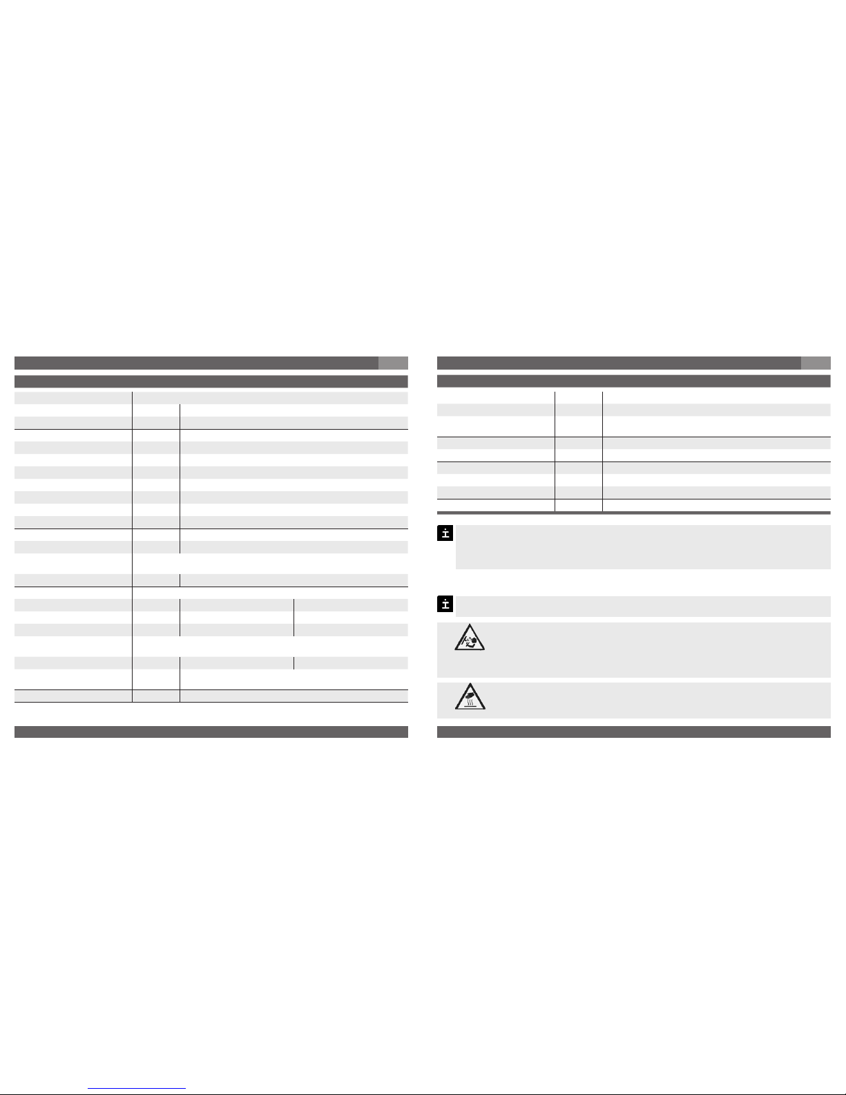
Specifications Model HP-1
Pressure ranges
1)
bar 1,600 2,500 4,000 5,000 6,000 7,000 8,000
Over pressure safety bar 2,300 3,500 5,000 6,000 7,000 8,000 10,000
Burst pressure bar 4,000 6,000 8,000 10,000 11,000 11,000 12,000
1)
> 8,000 bar on request
Materials
Wetted parts Stainless steel
Case Stainless steel
Power supply UB UB in VDC 10 ... 30 (14 … 30 with signal output 0 … 10 V)
Signal output and RA in Ohm 4 … 20 mA, 2-wire RA ≤ (UB – 10 V) / 0.02 A
maximum ohmic load RA {0 … 5 V, 3-wire} RA > 5,000
{0 … 10 V, 3-wire} RA > 10,000
{Other signal output on request}
Adjustability zero/span %
± 5 using potentiometers inside the instrument
Response time (10 ... 90 %) ms
≤ 1
Insulation voltage VDC 500
Accuracy % of span
≤ 0.25 (BFSL)
≤ 0.5
2)
2)
Including non-linearity, hysteresis, zero point and full scale error (corresponds to
error of measurement per IEC 61298-2).
Non-linearity % of span
≤ 0.2 (BFSL) according to IEC 61298-2
1-year stability % of span
≤ 0.2 (at reference conditions)
Permissible temperature of
Medium
3)
-0 ... +80 °C 32 ... +176 °F
Ambience
3)
-20 ... +80 °C -4 ... +176 °F
Storage
3)
-40 ... +85 °C -40 ... +185 °F
3)
Also complies with EN 50178, Tab. 7, Operation (C) 4K4H, Storage (D) 1K4,
Transport (E) 2K3
Specifications Model HP-2
Pressure ranges bar 1,600 2,500 4,000 5,000 6,000 7,000 8,000 10,000
Over pressure safety bar 2,300 3,500 5,000 6,000 7,000 8,000 10,000 11,000
Burst pressure bar 4,000 6,000 8,000 10,000 11,000 11,000 12,000 12,000
Pressure ranges psi 23,000 36,000 58,000 72,000 87,000 100,000 115,000 145,000
Over pressure safety psi 33,300 50,500 72,500 87,000 101,500 116,000 145,000 159,500
Burst pressure psi 58,000 87,000 116,000 145,000 159,500 159,500 174,000 174,000
Up to 15,000 bar / 217,000 psi on request
Specifications Model HP-1
Rated temperature range 0 ... +80 °C 32 ... +176 °F
Temperature coefficients within
rated temperature range
Mean TC of zero % of span
≤ 0.2 / 10 K
Mean TC of range % of span
≤ 0.2 / 10 K
CE- conformitiy
Pressure equipment directive 97/23/EC
EMC directive 89/336/EEC emission (class B) and immunity according to EN 61 326
Shock resistance g 100 according to IEC 60068-2-27 (mechanical shock)
Vibration resistance g 5 according to IEC 60068-2-6 (vibration under resonance)
Wiring protection
Short-circuit proofness Sig+ towards UB-
Reverse polarity protection UB+ towards UB-
Weight kg Approx. 0.3
7. Starting, operation
GB
7. Starting, operation
GB
{ } Items in curved brackets are optional extras for additional price.
Page 7
11379180.01 GB/D/F/E 08/2008
12
WIKA Operating instructions/Betriebsanleitung/Mode d'emploi/Instrucciones de servicio HP-1/HP-2
11379180.01 GB/D/F/E 08/2008
13
WIKA Operating instructions/Betriebsanleitung/Mode d'emploi/Instrucciones de servicio HP-1/HP-2
Specifications Model HP-2
Materials
Wetted parts 1.4534
Case Stainless steel
Power supply UB UB in VDC 10 ... 30 (14 … 30 with signal output 0 … 10 V)
Signal output and RA in Ohm 4 … 20 mA, 2-wire RA ≤ (UB – 10 V) / 0.02 A
maximum ohmic load RA 0 … 5 V, 3-wire RA > 5,000
0 … 10 V, 3-wire RA > 10,000
Other signal output on request
Adjustability zero %
± 5 using potentiometers inside the instrument
Response time (10 ... 90 %) ms
≤ 1
Insulation voltage VDC 500
Accuracy % of span
≤ ± 0.5 *
)
% of span
≤ ± 0.25 *) on request
*) Including non-linearity, hysteresis, zero point and full scale error (corresponds to
error of measurement per IEC 61298-2).
1-year stability % of span
≤ 0.1 (at reference conditions)
Permissible temperature of
Medium **
)
-0 ... +80 °C 32 ... +176 °F
Ambience **
)
-20 ... +80 °C -4 ... +176 °F
Storage **
)
-40 ... +85 °C -40 ... +185 °F
**) Also complies with EN 50178, Tab. 7, Operation (C) 4K4H, Storage (D) 1K4,
Transport (E) 2K3
Rated temperature range 0 ... +80 °C 32 ... +176 °F
Temperature error within
rated temperature range
%
≤ 1.0 typ.
≤ 2.5 max.
RoHS- conformitiy on request
Specifications Model HP-2
CE- conformitiy
Pressure equipment directive 97/23/EC
EMC directive
2004/108/EC, EN 61 326 Emission (Group 1, Class B) and Immunity
(industrial locations)
Shock resistance g 100 (2.4 ms) according to IEC 60068-2-27
Vibration resistance mm 0.35 (10 ... 55 Hz) according to IEC 60068-2-6
Wiring protection
Short-circuit proofness Sig+ towards UB-
Reverse polarity protection UB+ towards UB-
Weight kg Approx. 0.3
7. Starting, operation
GB
When designing your plant, take into account that the stated values (e.g.burst pressure, over pressure safety) apply depending on the material and thread used.
The respective values for your mounting torque and maximum pressure please
find in the documentation of your high-pressure equipment supplier.
7. Starting, operation
GB
Functional test
Open pressure connections only after the system is without pressure!
Observe the ambient and working conditions outlined in section 7 „Technical
data".
Please make sure that the pressure transmitter is only used within the overload threshold limit at all times!
When touching the pressure transmitter, keep in mind that the surfaces of
the instrument components might get hot during operation.
The output signal must be proportional to the pressure. If not, this might point to a
damage of the diaphragm. In that case refer to chapter 10 „Troubleshooting“.
Warning
Caution
Page 8

11379180.01 GB/D/F/E 08/2008
14
WIKA Operating instructions/Betriebsanleitung/Mode d'emploi/Instrucciones de servicio HP-1/HP-2
11379180.01 GB/D/F/E 08/2008
15
WIKA Operating instructions/Betriebsanleitung/Mode d'emploi/Instrucciones de servicio HP-1/HP-2
Failure Possible cause Procedure
No output signal Cable break Check connections and cable
No/incorrect voltage supply or current
spike
Adjust the voltage supply to correspond
with the Operating Instructions *)
No/False output signal
Incorrectly wired (e.g. Connected as
2-wire instead of 3-wire system)
Follow pin assignment (see Instrument
Label / Operating Instructions)
Z = Zero
S = Span
Female
connector
Sealing
Clamping
nut
Male
connector
Sealing
Case with
pressure
connection
Recommended recalibration cycle:
half-yearly
For further information
(+49) 9372/132-295
8. Adjustment of zero point / span
(only for pressure transmitter with clamping nut)
A
B
We do not recommend to adjust the span potentiometer. It is used for adjustment ex
factory and should not be adjusted by you unless you have adequate calibration equipment at your disposal (at least three times more accurate than the instrument being
tested).
8. Adjustment of zero point / span
GB
Make sure wires are not cut or pinche
during disassembly and reassembly of
the connector.
Remove the female connector. Open
the pressure transmitter by detaching
the clamping nut (see Fig. A ). Carefully
remove the male connector from the
case.
Adjust the zero point (Z) (see Fig. B ) by
generating the lower limit of the pressure
range.
Adjust the span (S) by generating the
higher limit of the pressure range.
Check the zero point.
If the zero point is incorrect, repeat
procedure as required.
Reassemble the instrument carefully.
Make sure all sealings and o-rings are
not damaged and correctly installed to
assure the rated moisture ingress protection.
9. Maintenance, accessories / 10. Trouble shooting
GB
9. Maintenance, accessories
Accessories
For details about the accessories (e. g. connectors), please refer to WIKA‘s price list, WIKA‘s
product catalog on CD or or contact our sales department.
10. Trouble shooting
Open pressure connections only after the system is without pressure!
WIKA pressure transmitters require no maintenance.
Have repairs performed by the manufacturer only.
Do not insert any pointed or hard objects into the pressure port for cleaning to prevent
damage to the diaphragm of the pressure connection.
Take precautions with regard to remaining media in removed pressure transmitters. Remaining media in the pressure port may be hazardous or
toxic!
Remove the pressure transmitter from service and mark it to prevent it from
being used again accidentally, if it becomes damaged or unsafe for operation.
Have repairs performed by the manufacturer only.
Please verify in advance if pressure is being applied (valves/ ball valve etc. open) and if the
right voltage supply and the right type of wiring (2-wire/ 3-wire) has been chosen?
Warning
!
Warning
Page 9

11379180.01 GB/D/F/E 08/2008
16
WIKA Operating instructions/Betriebsanleitung/Mode d'emploi/Instrucciones de servicio HP-1/HP-2
11379180.01 GB/D/F/E 08/2008
17
WIKA Operating instructions/Betriebsanleitung/Mode d'emploi/Instrucciones de servicio HP-1/HP-2
Failure Possible cause Procedure
Output signal unchanged after change
in pressure
Wrong supply voltage or current spike Replace instrument
Abnormal output signal
Change of the zero point due to pressure dynamics
Adjust zero point
Signal span too high Pressure peaks / Cavitations
Use a instrument with cavitation and
peak pressure protection
Signal span too small Power supply too high/too low
Correct the power supply in line with
the Operating Instructions
Signal span erratic
Electromagnetic interference source in
the vicinity, e.g. inverter drive
Shield the device; shield the cables;
remove the interference source
Violent fluctuations in the process
media pressure
Damping; consult with manufacturer
Instrument not grounded Ground instrument
Leakages at pressure connection Hairline cracks in pressure port
Consult with manufacturer (possilbly
reparation); Replace instrument
10. Trouble shooting
GB
In case of unjustified reclamation we charge the reclamation handling expenses.
*) Make sure that after the setting/the assembly the unit is working properly. In case the error continues to exist send in the instrument for
reparation (or replace the unit).
If the problem persists, contact our sales department.
Process material certificate (Contamination declaration for returned goods)
Purge / clean dismounted instruments before returning them in order to protect our employees
and the environment from any hazard caused by adherent remaining media.
Service of instruments can only take place safely when a Product Return Form has been
submitted and fully filled-in. This Return Form contains information on all materials with which
the instrument has come into contact, either through installation, test purposes, or cleaning.
You can find the Product Return Form on our internet site (www.wika.de / www.wika.com).
11. Storage, disposal
GB
11. Storage, disposal
When storing or disposing of the pressure transmitter, take precautions with
regard to remaining media in removed pressure transmitters. We recommend cleaning the transmitter properly and carefully. Remaining media in
the pressure port may be hazardous or toxic!
Mount the protection cap when storing the pressure transmitter in order to prevent any
damage to the sealing cone.
Dispose of instrument components and packaging materials in accordance with the
respective waste treatment and disposal regulations of the region or country to which
the instrument is supplied.
Storage
Disposal
WIKA reserves the right to alter these technical specifications.
!
Warning
Page 10

11379180.01 GB/D/F/E 08/2008
18
WIKA Operating instructions/Betriebsanleitung/Mode d'emploi/Instrucciones de servicio HP-1/HP-2
11379180.01 GB/D/F/E 08/2008
19
WIKA Operating instructions/Betriebsanleitung/Mode d'emploi/Instrucciones de servicio HP-1/HP-2
1. Wichiges zu Ihrer Information
D
Ihre erforderlichen Kenntnisse: Montieren und nehmen Sie das Druckmessgerät nur in
Betrieb, wenn Sie mit den zutreffenden landesspezifischen Richtlinien vertraut sind und
die entsprechende Qualifikation besitzen. Sie müssen mit den Kenntnissen von Mess- und
Regeltechnik sowie elektrischen Stromkreisen vertraut sein, da das Druckmessgerät ein
„elektrisches Betriebsmittel“ nach EN 50178 ist. Je nach Einsatzbedingung müssen Sie über
entsprechendes Wissen verfügen, z. B. über agressive Medien bzw. hohe Drücke.
1. Wichtiges zu Ihrer Information
Lesen Sie diese Betriebsanleitung vor Montage und Inbetriebnahme des Druckmessgerätes.
Bewahren Sie die Betriebsanleitung an einem für alle Benutzer jederzeit zugänglichen Ort auf.
Die nachfolgenden Einbau- und Betriebshinweise haben wir mit Sorgfalt zusammengestellt.
Es ist jedoch nicht möglich, alle erdenklichen Anwendungsfälle zu berücksichtigen. Sollten Sie
Hinweise für Ihre spezielle Aufgabenstellung vermissen, können Sie hier weitere Informationen
finden:
Über unsere Internet-Adresse www.wika.de / www.wika.com
Die Bezeichnung des zugehörigen Datenblattes ist PE 81.29 (HP-1) / PE 81.53 (HP-2)
Anwendungsberater: (+49) 9372/132-295
Bei Sondertypennummer, z.B. HP-20000, beachten Sie die Spezifikationen gemäß Lieferschein. Wird die Seriennummer auf dem Typenschild und/oder der 2D-Code auf dem
Sechskant unleserlich (z. B. durch mechanische Beschädigung oder Übermalen), ist eine
Rückverfolgbarkeit nicht mehr möglich.
Die in der Betriebsanleitung beschriebenen WIKA-Druckmessgeräte werden nach den
neuesten Erkenntnissen konstruiert und gefertigt. Alle Komponenten unterliegen während der
Fertigung strengen Qualitäts- und Umweltkriterien. Unser Umweltmanagementsystem ist nach
DIN EN ISO 14001 zertifiziert.
Auf Grund der extremen Belastungen, denen die hochdruckbeaufschlagten Materialien ausgesetzt sind, ist eine Dauerlastwechselfestigkeit nur bedingt gegeben. Dies gilt insbesondere für
dynamische Anwendungen. Dementsprechend handelt es sich bei den druckbelasteten Teilen
des HP-1 / HP-2 um Verschleißteile, die nicht unter die Gewährleistung fallen.
Bestimmungsgemäße Produktverwendung HP-1/HP-2:
Verwenden Sie den Druckmessumformer, um in Hochdruck-Applikationen > 1000 bar den
Druck in ein elektrisches Signal zu wandeln.
2. Schneller Überblick / 3. Zeichenerklärungen, Abkürzungen / 4. Funktion
D
2-Leiter Zwei Anschlussleitungen dienen zur Spannungsversorgung.
Der Speisestrom ist das Mess-Signal.
3-Leiter Zwei Anschlussleitungen dienen zur Spannungsversorgung.
Eine Anschlussleitung dient für das Mess-Signal.
UB Positiver Versorgungsanschluss
S+ Positiver Messanschluss
0V Negativer Versorgungsanschluss
4. Funktion
Mittels Sensorelement und unter Zuführung von Hilfsenergie wird über die Verformung einer
Membran der anstehende Druck in Ihrer Anwendung in ein verstärktes standardisiertes elektrisches Signal umgewandelt. Dieses elektrische Signal verändert sich proportional zum Druck
und kann entsprechend ausgewertet werden.
3. Zeichenerklärungen, Abkürzungen
Mögliche Gefahr für Ihr
Leben oder schwerer
Verletzungen.
Hinweis, wichtige Information, Funktionsstörung.
Das Produkt stimmt mit den
zutreffenden europäischen
Richtlinien überein.
Mögliche Gefahr für Ihr
Leben oder schwerer Verletzungen durch wegschleudernde Teile.
Mögliche Gefahr von
Verbrennungen durch
heisse Oberflächen.
2. Der schnelle Überblick für Sie
Wollen Sie sich einen schnellen Überblick verschaffen, lesen Sie Kapitel 3, 5, 7 und 11. Dort
erhalten Sie kurze Hinweise zu Ihrer Sicherheit und wichtige Informationen über Ihr Produkt
und zur Inbetriebnahme. Lesen Sie diese unbedingt.
!
Warnung
Vorsicht
Warnung
Page 11

11379180.01 GB/D/F/E 08/2008
20
WIKA Operating instructions/Betriebsanleitung/Mode d'emploi/Instrucciones de servicio HP-1/HP-2
11379180.01 GB/D/F/E 08/2008
21
WIKA Operating instructions/Betriebsanleitung/Mode d'emploi/Instrucciones de servicio HP-1/HP-2
5. Zu Ihrer Sicherheit
D
5. Zu Ihrer Sicherheit
Angaben zu Korrosions- bzw. Diffusionsbeständigkeit der Gerätewerkstoffe entnehmen Sie
bitte unserem WIKA-Handbuch zur Druck- und Temperaturmesstechnik.
Wählen Sie das richtige Druckmessgerät hinsichtlich Messbereich, Ausführung und spezifischen Messbedingungen vor Montage oder Inbetriebnahme.
Halten Sie die entsprechenden landesspezifischen Vorschriften ein (z. B.:
EN 50178) und beachten Sie bei speziellen Anwendungen die geltenden
Normen und Richtlinien. Wenn Sie die entsprechenden Vorschriften nicht
beachten, können schwere Körperverletzungen und Sachschäden
entstehen!
Öffnen Sie Anschlüsse nur im drucklosen Zustand!
Betreiben Sie das Druckmessgerät immer innerhalb des Überlastgrenzbereiches!
Beachten Sie die Betriebsparameter gemäß Punkt 7 „Technische Daten“.
Stellen Sie sicher, dass das Druckmessgerät nur bestimmungsgemäß -also wie in der
folgenden Anleitung beschrieben- betrieben wird.
Unterlassen Sie unzulässige Eingriffe und Änderungen am Druckmessgerät, welche nicht
in dieser Betriebsanleitung beschrieben sind.
Setzen Sie das Druckmessgerät außer Betrieb und schützen Sie es gegen versehentliche
Inbetriebnahme, wenn Sie Störungen nicht beseitigen können.
Ergreifen Sie Vorsichtsmaßnahmen für Messstoffreste in ausgebauten Druckmess-
geräten. Messstoffreste können zur Gefährdung von Menschen, Umwelt und Einrich-
tung führen!
Lassen Sie Reparaturen nur vom Hersteller durchführen.
Bitte beachten Sie, dass in einem System das Bauteil mit dem niedrigsten Maximaldruck
den höchstzulässigen Betriebsdruck für das Gesamtsystem festlegt, auch wenn einzelne
Komponenten durchaus höheren Belastungen ausgesetzt werden dürfen. Ist mit schwan-
kenden oder unterschiedlichen Drücken im System zu rechnen, sollten Komponenten zum
Einsatz kommen, die den höchsten zu erwartenden Druckspitzen standhalten können.
Treffen Sie geeignete Schutzmaßnahmen, die ein Herausschleudern von
Teilen im Fehlerfall verhindern. Diese Schutzvorrichtungen dürfen nicht ohne
Werkzeug entfernbar sein.
6. Verpackung / 7. Inbetriebnahme, Betrieb
D
6. Verpackung
Zum Schutz des Dichtkonus ist der Druckanschluss des Gerätes HP-1 / HP-2 mit einer speziellen Schutzkappe versehen.
7. Inbetriebnahme, Betrieb
Überprüfen Sie den Lieferumfang:
Komplett montierte Druckmessgeräte
Untersuchen Sie das Druckmessgerät auf eventuell entstandene Transportschäden.
Sind offensichtlich Schäden vorhanden, teilen Sie dies dem Transportunternehmen
und WIKA unverzüglich mit.
Bewahren Sie die Verpackung auf, denn diese bietet bei einem Transport einen optimalen Schutz (z. B. wechselnder Einbauort, Reparatursendung).
Achten sie darauf, dass das Druckanschluss-Gewinde und die Anschlusskontakte
nicht beschädigt werden.
Entfernen Sie diese Schutzkappe erst kurz vor dem Einbau, damit Dichtkonus bzw.
das Druckanschluss-Gewinde nicht beschädigt wird.
Bewahren Sie die Schutzkappe des Druckanschluss-Gewindes und der Membran zur
späteren Lagerung oder Transport auf.
Montieren Sie die Schutzkappe bei Ausbau und Transport des Gerätes.
Benötigtes Werkzeug: Maulschlüssel SW 27, Schraubendreher
Setzen Sie das Druckmessgerät nur in sicherheitstechnisch einwandfreiemZustand ein.
Membran-Prüfung zu Ihrer Sicherheit
Wurde alles geliefert?
!
Warnung
!
Warnung
Page 12

11379180.01 GB/D/F/E 08/2008
22
WIKA Operating instructions/Betriebsanleitung/Mode d'emploi/Instrucciones de servicio HP-1/HP-2
11379180.01 GB/D/F/E 08/2008
23
WIKA Operating instructions/Betriebsanleitung/Mode d'emploi/Instrucciones de servicio HP-1/HP-2
Elektrische Anschlüsse
Winkeldose
DIN 175301-803 A
Rundsteckverbinder
M12x1
Kabelausgang
2-Leiter UB = 1 0V = 2 UB = 1 0V = 3 UB = braun 0V = grün
3-Leiter UB = 1 0V = 2 S+ = 3 UB = 1 0V = 3 S+ = 4 UB = braun 0V = grün S+ = weiß
Aderquerschnitt bis max. 1,5 mm
2
- 0,5 mm2 (AWG 20)
Kabeldurchmesser 6-8 mm - 6,8 mm
Schutzart nach IEC 60 529 IP 65 IP 67 IP 67
Die angegebenen Schutzarten gelten nur im gesteckten Zustand mit Leitungssteckern
entsprechender Schutzart.
7. Inbetriebnahme, Betrieb
D
Montage mechanischer Anschluss
Signal
Spannungsversorgung
Codiertes Herstelldatum
Serien-Nr.
Erzeugnis-Nr.
Typenschild (Beispiele)
Es gilt grundsätzlich die Seriennummer auf dem
Typenschild. Befindet sich keine Seriennummer
auf dem Typenschild, so gilt die Nummer auf dem
Sechskant.
P #
Entnehmen Sie den Druckmessumformer der Verpackung und vergewissern Sie
sich anhand des Typenschildes, dass der von Ihnen benötigte Typ vorliegt.
Achten Sie bei der Montage auf saubere und unbeschädigte Dichtflächen am Gerät
und Messstelle.
Schrauben Sie das Gerät nur über die Schlüsselflächen mit einem geeigneten Werkzeug und dem vorgeschriebenen Drehmoment ein bzw. aus. Das richtige Drehmoment ist abhängig von der Dimension des Druckanschlusses sowie der verwendeten
Dichtung (Form/Werkstoff). Verwenden Sie zum Ein- bzw. Ausschrauben nicht das
Gehäuse als Angriffsfläche.
Die für Ihre Montagestelle gültigen Werte für Anzugsmoment und Maximaldruck
entnehmen Sie bitte den Unterlagen Ihres HD-Rohr-Lieferanten.
Beachten Sie beim Einschrauben, dass die Gewindegänge nicht verkantet werden.
S #
7. Inbetriebnahme, Betrieb
D
Betreiben Sie den Druckmessumformer mit geschirmter Leitung und erden Sie den
Schirm auf mindestens einer Leitungsseite, wenn die Leitungen länger als 30m (2Leiter) bzw. 3m (3- bzw. 4-Leiter) sind oder das Gebäude verlassen.
Verwenden Sie ausschließlich Stromquellen, die eine sichere elektrische Trennung
der Betriebsspannung nach IEC/DIN EN 60204-1 gewährleisten. Berücksichtigen Sie
zusätzlich die allgemeinen Anforderungen an PELV-Stromkreise gemäß
IEC/DIN EN 60204-1.
Schutzart IP nach IEC 60 529 (Die angegebenen Schutzarten gelten nur im gesteckten
Zustand mit Leitungsteckern (Buchsen) entsprechender Schutzart).
Wählen Sie den Kabeldurchmesser passend zur Kabeldurchführung des Steckers.
Achten Sie darauf, dass die Kabelverschraubung des montierten Steckers korrekt
sitzt und dass die Dichtungen vorhanden und nicht beschädigt sind. Ziehen Sie die
Verschraubung fest und überprüfen Sie den korrekten Sitz der Dichtungen, um die
Schutzart zu gewährleisten.
Stellen Sie bei Kabelausgängen sicher, dass am Ende des Kabels keine Feuchtigkeit
eintritt.
Montage elektrischer Anschluss
Erden Sie das Gerät über den Druckanschluss.
Anschlussbelegung
Page 13

11379180.01 GB/D/F/E 08/2008
24
WIKA Operating instructions/Betriebsanleitung/Mode d'emploi/Instrucciones de servicio HP-1/HP-2
11379180.01 GB/D/F/E 08/2008
25
WIKA Operating instructions/Betriebsanleitung/Mode d'emploi/Instrucciones de servicio HP-1/HP-2
Technische Daten Typ HP-1
Messbereich
1)
bar 1.600 2.500 4.000 5.000 6.000 7.000 8.000
Überlastgrenze bar 2.300 3.500 5.000 6.000 7.000 8.000 10.000
Berstdruck bar 4.000 6.000 8.000 10.000 11.000 11.000 12.000
1)
> 8.000 bar auf Anfrage
Werkstoff
Messstoffberührte Teile CrNi-Stahl
Gehäuse CrNi-Stahl
Hilfsenergie UB UB in VDC 10 ... 30 (14 … 30 bei Ausgang 0 … 10 V)
Ausgangssignal und zulässige RA in Ohm 4 … 20 mA, 2-Leiter RA ≤ (UB – 10 V) / 0.02 A
max. ohmsche Bürde RA {0 … 5 V, 3-Leiter} RA > 5.000
{0 … 10 V, 3-Leiter} R
A > 10.000
{Andere Ausgangssignale auf Anfrage}
Einstellbarkeit Nullpunkt/Spanne %
± 5 durch Potentiometer im Gerät
Einstellzeit (10 ... 90 %) ms
≤ 1
Spannungsfestigkeit VDC 500
Genauigkeit % d. Spanne
≤ ± 0,25 (BFSL)
≤ ± 0,5
2)
2)
Einschließlich Nichtlinearität, Hysterese, Nullpunkt- und Endwertabweichung
(entspricht Messabweichung nach IEC 61298-2).
Nichtlinearität % d. Spanne
≤ 0,2 (BFSL) nach IEC 61298-2
Stabilität pro Jahr % d. Spanne
≤ 0,2 (bei Referenzbedingungen)
Zulässige Temperaturbereiche
Messstoff
3)
0 ... +80 °C
Umgebung
3)
-20 ... +80 °C
Lagerung
3)
-40 ... +85 °C
3)
Erfüllt auch EN 50178, Tab. 7, Betrieb (C) 4K4H, Lagerung (D) 1K4,
Transport (E) 2K3
(D) Montageöffnung
Montage des Winkelsteckverbinder nach DIN EN 175301-803
(6)
(5)
(1)
(2)
(3)
(4)
Griffring,
Gerätestecker(Stift),
Gehäuse mit
Druckanschluss
Dichtung
Leitungsstecker
(Buchse)
1. Lösen Sie die Schraube (1).
2. Lösen Sie die Kabelverschraubung (2).
3. Ziehen Sie Winkelgehäuse (5)mit Klemm block (6) vom Gerät ab.
4. Hebeln Sie mit dem Schraubendreher in
die Montageöffnung (D), so dass Sie den
Klemmblock (6) aus dem Winkelgehäuse (5)
herausdrücken. Drücken Sie nicht den
Klemmblock (6) durch die Schraubenöffnung (1) bzw. Kabelverschraubung (2) heraus,
sonst beschädigen Sie die Dichtungen des Winkelgehäuses.
5. Wählen Sie den Leitungsaußendurchmesser passend zur Kabeldurchführung des Winkel
gehäuses. Schieben Sie das Kabel durch Kabelverschraubung (2), Ring (3), Dichtung (4)
und Winkelgehäuse (5).
6. Schließen Sie die Kabelenden entsprechend der Belegungszeichnung in den Anschluß
klemmen des Klemmblocks (6) an.
7. Drücken Sie das Winkelgehäuse (5) auf den Klemmblock (6).
8. Verschrauben Sie das Kabel mit der Kabelverschraubung (2). Achten Sie darauf, dass die
Dichtungen unbeschädigt sind und Kabelverschraubung und Dichtungen korrekt sitzen,
um die Schutzart zu gewährleisten.
9. Legen Sie die quadratische Flachdichtung über die Anschlußpins im Gehäuse.
10. Schieben Sie den Klemmblock (6) auf die Anschlußpins im Gehäuse.
11. Verschrauben Sie mit der Schraube (1) das Winkelgehäuse (5) mit dem Klemmblock (6) im
Gerät.
7. Inbetriebnahme, Betrieb
D
7. Inbetriebnahme, Betrieb
D
Page 14

11379180.01 GB/D/F/E 08/2008
26
WIKA Operating instructions/Betriebsanleitung/Mode d'emploi/Instrucciones de servicio HP-1/HP-2
11379180.01 GB/D/F/E 08/2008
27
WIKA Operating instructions/Betriebsanleitung/Mode d'emploi/Instrucciones de servicio HP-1/HP-2
Technische Daten Typ HP-1
Nenntemperaturbereich 0 ... +80 °C
Temperaturkoeffizienten im
Nenntemperaturbereich
Mittlerer TK des Nullpunktes % d. Spanne
≤ 0,2 / 10 K
Mittlerer TK der Spanne % d. Spanne
≤ 0,2 / 10 K
CE- Kennzeichen
Druckgeräterichtlinie 97/23/EG
EMV-Richtlinie
89/336/EWG Störemission (Grenzwertklasse B) und Störfestigkeit
nach EN 61 326
Schockbelastbarkeit g 100 nach IEC 60068-2-27 (Schock mechanisch)
Vibrationsbelastbarkeit g 5 nach IEC 60068-2-6 (Vibration bei Resonanz)
Elektrische Schutzarten
Kurzschlussschutz Sig+ gegen UB-
Verpolschutz UB+ gegen UB-
Gewicht kg Ca. 0,3
Technische Daten Typ HP-2
Messbereich bar 1.600 2.500 4.000 5.000 6.000 7.000 8.000 10.000
Überlastgrenze bar 2.300 3.500 5.000 6.000 7.000 8.000 10.000 11.000
Berstdruck bar 4.000 6.000 8.000 10.000 11.000 11.000 12.000 12.000
psi 23.000 36.000 58.000 72.000 87.000 100.000 115.000 145.000
psi 33.300 50.500 72.500 87.000 101.500 116.000 145.000 159.500
psi 58.000 87.000 116.000 145.000 159.500 159.500 174.000 174.000
Bis 15.000 bar / 217.000 psi auf Anfrage
Werkstoff
Messstoffberührte Teile 1.4534
Gehäuse CrNi-Stahl
Technische Daten Typ HP-2
Hilfsenergie UB UB in VDC 10 ... 30 (14 … 30 bei Ausgang 0 … 10 V)
Ausgangssignal und zulässige RA in Ohm 4 … 20 mA, 2-Leiter RA ≤ (UB – 10 V) / 0,02 A
max. ohmsche Bürde RA 0 … 5 V, 3-Leiter RA > 5.000
0 … 10 V, 3-Leiter RA > 10.000
Andere Ausgangssignale auf Anfrage
Einstellbarkeit Nullpunkt %
± 5 durch Potentiometer im Gerät
Einstellzeit (10 ... 90 %) ms
≤ 1
Isolationsspannung VDC 500
Genauigkeit % d. Spanne
≤ ± 0,5 *
)
≤ ± 0,25 *) auf Anfrage
*) Einschließlich Nichtlinearität, Hysterese, Nullpunkt- und Endwertabweichung
(entspricht Messabweichung nach IEC 61298-2).
Stabilität pro Jahr % d. Spanne
≤ 0,1 (bei Referenzbedingungen)
Zulässige Temperaturbereiche
Messstoff **
)
°C 0 ... +80
Umgebung **
)
°C -20 ... +80
Lagerung **
)
°C -40 ... +85
**
)
Erfüllt auch EN 50178, Tab. 7, Betrieb (C) 4K4H, Lagerung (D) 1K4,
Transport (E) 2K3
Nenntemperaturbereich °C 0 ... +80
Temperaturfehler im
Nenntemperaturbereich
%
≤ 1,0 typ.
≤ 2,5 max.
RoHS-Konformität auf Anfrage
CE-Konformität
Druckgeräterichtlinie 97/23/EG
EMV-Richtlinie
2004/108/EG, EN 61326 Emission (Gruppe 1, Klasse B) und
Störfestigkeit (industrieller Bereich)
7. Inbetriebnahme, Betrieb
D
{ } Angaben in geschweiften Klammern beschreiben gegen Mehrpreis lieferbare Sonderheiten.
7. Inbetriebnahme, Betrieb
D
Page 15

11379180.01 GB/D/F/E 08/2008
28
WIKA Operating instructions/Betriebsanleitung/Mode d'emploi/Instrucciones de servicio HP-1/HP-2
11379180.01 GB/D/F/E 08/2008
29
WIKA Operating instructions/Betriebsanleitung/Mode d'emploi/Instrucciones de servicio HP-1/HP-2
Technische Daten Typ HP-2
Schockbelastbarkeit g 100 (2,4 ms) nach IEC 60068-2-27
Vibrationsbelastbarkeit mm 0,35 (10 ... 55 Hz) nach IEC 60068-2-6
Elektrische Schutzarten
Kurzschlussschutz Sig+ gegen UB-
Verpolschutz UB+ gegen UB-
Gewicht kg Ca. 0,3
Beachten Sie bei der Auslegung Ihrer Anlage, dass die angegebenen Werte (z. B.
Berstdruck, Überlastgrenze) in Abhängigkeit vom verwendeten Material und Gewinde
gelten.
Die für Ihre Montagestelle gültigen Werte für Anzugsmoment und Maximaldruck
entnehmen Sie bitte den Unterlagen Ihres HD-Rohr-Lieferanten.
7. Inbetriebnahme, Betrieb / 8. Einstellung Nullpunkt / Spanne
D
Funktionsprüfung
Öffnen Sie Anschlüsse nur im drucklosen Zustand!
Beachten Sie die Betriebsparameter gemäß Punkt 7„Technische Daten“.
Betreiben Sie das Druckmessgerät immer innerhalb des Überlastgrenzbereichs!
Beachten Sie beim Berühren des Druckmessgerätes, dass die Oberflächen
der Gerätekomponenten während des Betriebes heiß werden können.
Das Ausgangssignal muss sich dem anstehenden Druck proportional verhalten. Wenn
dies nicht so ist, kann das ein Hinweis auf eine Beschädigung der Membran sein. Lesen
Sie in diesem Fall in Kapitel 10 „Störbeseitigung“ nach.
8. Einstellung Nullpunkt / Spanne (nur bei Geräten mit Griffring)
Wir empfehlen Ihnen, das Spannepotentiometer nicht zu verstellen. Es dient zur werkseitigen Justage und sollte nur von Ihnen verstellt werden, wenn Sie über die ausreichende Kalibrierausstattung (mindestens 3x genauer als die angegebene Genauigkeit)
verfügen.
Z = Nullpunkt
S = Spanne
Leitungsstecker
(Buchse)
Dichtung
Griffring
Gerätestecker
(Stift)
Dichtung
Gehäuse
mit Druckanschluss
Empfohlener Nachkalibrier-Zyklus:
halbjährlich
Bei Rückfragen (+49) 9372/132-295
A
B
8. Einstellung Nullpunkt / Spanne / 9. Wartung, Zubehör
D
Achten Sie bei der Steckerdemontage /montage darauf, dass keine Litzen
abgerissen bzw. eingequetscht werden.
Ziehen Sie den Leitungstecker(Buchse)
ab. Öffnen Sie das Druckmessgerät,
indem Sie den Griffring lösen (siehe
Abbildung A ). Ziehen Sie vorsichtig den
Gerätestecker(Stift) aus dem Gehäuse.
Stellen Sie den Nullpunkt (Z) ein (siehe
Abbildung B ), indem Sie den Druckan-
fangswert anfahren.
Stellen Sie die Spanne (S) ein, indem
Sie den Druckendwert anfahren.
Überprüfen Sie den Nullpunkt.
Wenn der Nullpunkt nicht stimmt ggf.
Prozedur wiederholen.
Schließen Sie das Druckmessgerät wieder
sorgfältig. Ziehen Sie den Griffring mit
5 Nm an. Achten Sie darauf, dass die
Dichtungen unbeschädigt und sauber
sind und auf die korrekte Lage der Dich-
tungen, um die Schutzart zu gewährleisten.
9. Wartung, Zubehör
Zubehör
Entnehmen Sie bitte Zubehörangaben (z. B. Stecker) unserer aktuellen Standardpreisliste, dem
CD-Katalog oder setzen Sie sich mit unserem Vertriebsmitarbeiter in Verbindung.
WIKA Druckmessgeräte sind wartungsfrei.
Lassen Sie Reparaturen nur vom Hersteller durchführen.
Warnung
Vorsicht
Page 16

11379180.01 GB/D/F/E 08/2008
30
WIKA Operating instructions/Betriebsanleitung/Mode d'emploi/Instrucciones de servicio HP-1/HP-2
11379180.01 GB/D/F/E 08/2008
31
WIKA Operating instructions/Betriebsanleitung/Mode d'emploi/Instrucciones de servicio HP-1/HP-2
Störung Mögliche Ursache Maßnahme
Kein Ausgangssignal Leitungsbruch Durchgang überprüfen
Keine/Falsche Versorgungsspannung
oder Stromstoß
Versorgungsspannung gemäß Betriebsanleitung korrigieren *)
Kein/Falsches Ausgangssignal
Verdrahtungsfehler (z. B. 2-Leiter als
3-Leiter verdrahtet)
Anschlussbelegung beachten (siehe
Typenschild / Betriebsanleitung)
Gleichbleibendes Ausgangssignal bei
Druckänderung
Falsche Versorgungsspannung oder
Stromstoß
Gerät austauschen
Abweichendes Ausgangssignal
Nullpunkt-Änderung durch Druckdynamik
Nullpunkt nachjustieren
Signalspanne zu hoch Druckspitzen / Kavitationen
Gerät mit Kavitation- und Druckspitzenschutz einsetzen
Signalspanne zu klein Versorgungsspannung zu hoch/niedrig
Versorgungsspannung gemäß Betriebsanleitung korrigieren
Störung Mögliche Ursache Maßnahme
Signalspanne schwankend
EMV-Störquellen in Umgebung, z. B.
Frequenzumrichter
Gerät abschirmen; Leitungsabschirmung; Störquelle entfernen
Stark schwankender Druck des
Prozessmediums
Dämpfung; Beratung durch Hersteller
Gerät nicht geerdet Gerät erden
Leckage am Druckanschluss Haarriss im Druckkanal
Beratung durch den Hersteller (evtl.
Reparatur); Gerät austauschen
10. Störbeseitigung
10. Störbeseitigung
Öffnen Sie Anschlüsse nur im drucklosen Zustand!
Verwenden Sie keine spitzen bzw. harten Gegenstände zur Reinigung, denn die
Membran des Druckanschlusses darf nicht beschädigt werden.
Ergreifen Sie Vorsichtsmaßnahmen für Messstoffreste in ausgebauten
Druckmessgeräten. Messstoffreste können zur Gefährdung von Menschen,
Umwelt und Einrichtung führen!
Setzen Sie das Druckmessgerät außer Betrieb und schützen Sie es gegen
versehentliche Inbetriebnahme, wenn Sie Störungen nicht beseitigen
können.
Lassen Sie Reparaturen nur vom Hersteller durchführen.
D
Prüfen Sie bitte vorab, ob Druck ansteht (Ventile/Kugelhahn usw. offen) und ob Sie die richtige
Spannungsversorgung und die richtige Verdrahtungsart (2-Leiter/3-Leiter) gewählt haben.
10. Störbeseitigung / 11. Lagerung, Entsorgung
D
Im unberechtigtem Reklamationsfall berechnen wir die Reklamationsbearbeitungs-Kosten.
*) Überprüfen Sie nach dem Justieren/der Montage die korrekte Arbeitsweise des Systems. Besteht der Fehler weiterhin, senden Sie das
Gerät zur Reparatur ein (oder tauschen Sie das Gerät aus).
Wenn das Problem bestehen bleibt, setzen Sie sich mit unserem Vertriebsmitarbeiter in Verbindung.
Prozess Material Zertifikat (Kontaminationserklärung im Servicefall)
Spülen bzw. säubern Sie ausgebaute Geräte vor der Rücksendung, um unsere Mitarbeiter und
die Umwelt vor Gefährdung durch anhaftende Messstoffreste zu schützen.
Eine Überprüfung ausgefallener Geräte kann nur sicher erfolgen, wenn das vollständig ausgefüllte Rücksendeformular vorliegt. Eine solche Erklärung beinhaltet alle Materialien, welche
mit dem Gerät in Berührung kamen, auch solche, die zu Testzwecken, zum Betrieb oder zur
Reinigung eingesetzt wurden. Das Rücksendeformular ist über unsere Internet-Adresse (www.
wika.de / www.wika.com) verfügbar.
11. Lagerung, Entsorgung
Ergreifen Sie bei Lagerung und Entsorgung Vorsichtsmaßnahmen für Messstoffreste in ausgebauten Druckmessgeräten. Wir empfehlen eine geeignete
und sorgfältige Reinigung. Messstoffreste können zur Gefährdung von
Menschen, Umwelt und Einrichtung führen!
Montieren Sie die Schutzkappe bei Lagerung des Druckmessgerätes, damit der Dichtkonus nicht beschädigt wird.
Lagerung
Entsorgen Sie Gerätekomponenten und Verpackungsmaterialien entsprechend den
einschlägigen landesspezifischen Abfallbehandlungs- und Entsorgungsvorschriften des
Anliefergebietes.
Entsorgung
Technische Änderungen vorbehalten.
Warnung
!
Warnung
Warnung
!
Page 17

11379180.01 GB/D/F/E 08/2008
32
WIKA Operating instructions/Betriebsanleitung/Mode d'emploi/Instrucciones de servicio HP-1/HP-2
11379180.01 GB/D/F/E 08/2008
33
WIKA Operating instructions/Betriebsanleitung/Mode d'emploi/Instrucciones de servicio HP-1/HP-2
1. Informations importantes
F
Veuillez lire ce mode d’emploi avant le montage et la mise en service de transmetteur de pression. Conservez ce mode d’emploi dans un endroit accessible en tout temps pour tous les
utilisateurs. Les instructions de montage et de service présentées ci-après ont été établi avec
grand soin. Il reste toutefois impossible d’envisager tous les cas d’applications possibles.
Dans le cas où vous constateriez des lacunes dans ces instructions pour les tâches spéciales
qu’il vous faut exécuter, vous avez la possibilité de recevoir des compléments d’informations:
Sous notre adresse internet www.wika.de / www.wika.com
La fiche technique de ce produit a la désignation PE 81.29 (HP-1) / PE 81.53 (HP-2)
Par contact direct avec notre conseiller applications (+49) 9372/132-295
Pour les modèles avec numéros spéciaux comme par exemple HP-20000, veuillez prendre en
considération les spécifications selon le bordereau de livraison.
Si le numéro de série sur la plaque de fabrication et/ou la codification 2D sur l’hexagone du
raccord n’est (ne sont) plus lisible (s) (par exemple par endommagement mécanique ou si le
numéro est recouvert de peinture), la traçabilité n’est plus assurée.
La conception et la fabrication des transmetteurs de mesure WIKA, tels que décrits dans les
instructions de service, satisfont aux toutes dernières règles de l’art. Tous les composants
sont soumis à un contrôle strict des critères de qualité et d’environnement en cours de fabrication. Notre système de gestion de l’environnement est certifié selon DIN EN ISO 14001.
En raison des charges externes auxquelles sont soumis les matériaux sur lesquels une haute
pression est appliquée, une résistance aux changements de pression n‘est indiquée que partiellement. Cela est surtout valable pour les applications dynamiques. Par conséquent, il s‘agit,
pour les pièces des convertisseurs de mesure à très haute pression HP-1 / HP-2 soumises à
une pression, de pièces d‘usure ne faisant pas partie de la garantie.
Vos connaissances nécessaires: N’installez et ne mettez en service le transmetteur de
pression que si vous avez les connaissances exactes des directives spécifiques nationales et
si vous êtes en possession de la qualification en rapport. Vous devez posséder des connaissances des prescriptions pour la technique de mesure et régulation et des circuits électriques
étant donné que le transmetteur de pression est un équipement électrique selon EN 50178.
Suivant les conditions d’utilisation vous devez disposer de connaissances parti-culières, par
exemple sur les fluides agressifs ou les hautes pression.
Définition conforme d’utilisation du produit HP-1/HP-2
Utilisez le transmetteur de pression afin de transformer la presssion en signal électrique dans
aux applications très hautes pressions > 1000 bar.
1. Informations importantes
1.Informationes importantes/2.Aperçu rapide/3.Explication des symboles,abréviations/4.Fonction
F
3. Explication des symboles,abréviations
Risque de danger de mort
ou de blessures graves.
Remarques, informations
importantes, dérangement
de fonction.
Ce produit est conforme
aux directives européennes
correspondantes.
Risque de danger de mort
ou de blessures graves par
des pièces éjectées.
Possibilité de danger de
brûlures par surfaces
brûlantes.
2-fils Deux conducteurs servent à l’alimentation.
Le courant de l’alimentation est le
signal de mesure.
3-fils Deux conducteurs servent à l’alimentation.
Un conducteur servent au signal de mesure.
4. Fonction: A l'aide d'un capteur et sous alimentation électrique, on obtient la transforma-
tion en un signal amplifié, normalisé et électrique de la pression appliquée, par la déformation
d'une membrane. Ce signal électrique varie proportionnellement par rapport à la pression et
peut être exploité en rapport.
2. Aperçu rapide
Si vous voulez vous procurer un résumé rapide, veuillez lire les chapitres 3, 5, 7 et 11. Là
vous trouverez des indications concernant votre sécurité et des informations importantes sur
votre produit et sa mise en service. Veuillez absolument en prendre connaissance.
UB Alimentation positive raccord
S+ Positive raccord mesure
OV- Alimentation négative raccord
!
Avertissement
Attention
Avertissement
Page 18

11379180.01 GB/D/F/E 08/2008
34
WIKA Operating instructions/Betriebsanleitung/Mode d'emploi/Instrucciones de servicio HP-1/HP-2
11379180.01 GB/D/F/E 08/2008
35
WIKA Operating instructions/Betriebsanleitung/Mode d'emploi/Instrucciones de servicio HP-1/HP-2
5. Pour votre sécurité
F
5. Pour votre sécurité
Choisissez le transmetteur de pression adéquat, avant le montage et la mise
en service, en rapport à l’étendue de mesure, l’exécution et les conditions
de mesure spécifiques
Respectez les prescriptions de sécurité nationales (comme par exemple:
EN 50178) et observez lors d’applications spéciales les normes et règlements en rigueur. Si vous ne respectez pas les prescriptions correspo-
dantes, de graves lésions corporelles et dégâts matériels peuvent en
résulter!
N’ouvrez les raccords que hors pression!
N'utilisez le transmetteur de pression qu'à l'intérieur de la zone limite!
Prenez en considération les paramètres de service selon le chapitre 7 „Caractéristiques
techniques”.
Assurez-vous que le transmetteur de pression ne soit utilisé qu’en accord avec le règlement, c’est-à-dire comme décrit dans la directive suivante.
Abstenez-vous d’effectuer des empiétements et changements inadmissibles sur le tranmetteur de pression n’étant pas décrits dans le mode d’emploi.
Si vous ne pouvez pas éliminer des dérangements sur le transmetteur de pression, mettez
celui-ci hors service et protégez le contre une remise en service par inadvertance.
Prenez des mesures de sécurité pour les restes de fluides se trouvant dans les transmetteurs de pression démontés. Ces restes de fluides peuvent mettrent en danger
les personnes, l’environnement ainsi que l’installation !
Ne faites effectuer les réparations que par le fabricant. Veuillez tenir compte du fait que,
dans un système, l‘élément conçu pour la pression la plus basse détermine la pression de
service maximale admissible pour le système entier, même si des composants individuels
pourraient être soumis à des charges plus élevées. Si, dans le système, il faut s‘attendre à
des pressions instables ou qui diffèrent, il convient d‘utiliser des composants résistant aux
pointes de pression maximales.
Prenez des mesures de protection adéquates qui empêchent la projection
de pièces en cas de défectuosité. Ces dispositifs de protection ne doivent
pas être démontables sans outillage.
5. Pour votre sécurité / 6. Emballage / 7. Mise en service, exploitation
F
Les données relatives à la résistance à la corrosion et diffusion des instruments se trouvent
dans le manuel WIKA sur la mesure des pressions et des températures.
6. Emballage
Est-ce que la livraison est complète ?
Contrôlez le volume de la livraison:
Transmetteurs de pression complets
Examinez le transmetteur de pression en vue de dommages éventuels résultant du
transport. Si des dommages sont évidents, veuillez en informer immédiatement
i’entreprise de transport et WIKA.
Conservez l’emballage, celui-ci offre lors d’un transport une protection optimale (par
exemple changement du lieu d’utilisation, renvoi pour réparation).
Veillez à ce que le filetage du raccord pression ainsi que les contacts de branchement
ne soient pas détériorés.
Afin de protéger le cône d'étanchéité, le raccord pression de l’appareil HP-1/HP-2 est muni
d’un capuchon de protection.
N’enlevez ce capuchon que juste avant le montage afin que le cône d'étanchéité ne
soit pas endommagée.
Conservez le capuchon de protection du filetage du raccord pression et la membrane
pour un stockage ou pour un transport futur.
Remontez le capuchon de protection lors du démontage ou transport de transmetteur
de pression.
7. Mise en service, exploitation
Outillage nécessaire: clé à fourche de 27, tournevis
Utilisez le transmetteur de pression uniquement s’il est dans un état parfait
quant à la sécurité technique.
!
Avertissement
!
Avertissement
Page 19

11379180.01 GB/D/F/E 08/2008
36
WIKA Operating instructions/Betriebsanleitung/Mode d'emploi/Instrucciones de servicio HP-1/HP-2
11379180.01 GB/D/F/E 08/2008
37
WIKA Operating instructions/Betriebsanleitung/Mode d'emploi/Instrucciones de servicio HP-1/HP-2
Branchement electrique
Connecteur coudé
DIN 175301-803 A
Connecteur M12x1 Sortie câble
2-fils UB = 1 0V = 2 UB = 1 0V = 3 UB = brun 0V = vert
3-fils UB = 1 0V = 2 S+ = 3 UB = 1 0V = 3 S+ = 4 UB = brun 0V = vert S+ = blanc
Section de conducteur
jusqu’à un maximum de
1,5 mm
2
- 0,5 mm2 (AWG 20)
Diamètre extérieur du
conducteur
6 à 8 mm - 6,8 mm
Protection selon IEC 60 529 IP 65 IP 67 IP 67
Les degrés de protection indiqués ne sont valables que pour les connecteurs enfichés avec
connecteurs femelles possédant l’indice de protection correspondant.
Fondamentalement est valable le numéro de
série sur la plaque de fabrication. S‘il n‘y a pas de
numéro de série sur la plaque de fabrication, le
numéro sur l‘hexagone est valable.
Montage du raccord Plaque de fabrication (exemple)
Sortez le transmetteur de son emballage et assurez vous au moyen de la plaque de
fabrication qu‘il s‘agit bien du type souhaité.
Veuillez faire attention lors du montage à ce que les surfaces d’étanchéité de
l’appareil et du point de mesure ne soient pas détériorées ou malpropres.
Serrez ou desserrez l’appareil uniquement par l’intermédiaire des surfaces pour clés
à l’aide d’un outil approprié en respectant le couple de serrage. Le couple de serrage
correct dépend de la dimension du raccord de pression ainsi que du joint utilisé
(forme / matière). Pour visser ou dévisser l’appareil, n’utilisez pas le boîtier en tant que
surface d’attaque.
Les valeurs qui conviennent à votre lieu de montage pour couple de montage et pression maxi figurent dans les documents de votre fournisseur de tuyaux haute pression.
Prenez garde lors du vissage de l’appareil, que le pas de vis ne se coince pas.
7. Mise en service, exploitation
F
7. Mise en service, exploitation
F
Utilisez uniquement des sources de courant qui garantissent une séparation électrique sûre de la tension de service conformément à la norme IEC/DIN EN 60204-1.
Tenez compte également des exigences générales concernant les circuits électriques
PELV conformément aux normes IEC/DIN EN 60204-1.
Protection IP selon IEC 60 529 (les degrés de protection indiqués ne sont valables
que pour les connecteurs enfichés avec connecteurs femelles possédant l’indice de
protection correspondant).
Choisissez le diamètre du câble en rapport au presse étoupe du connecteur. Faites
attention à ce que le serre-câble du connecteur assemblé soit bien positionné et que
les joints soient tous présents et non endommagés. Serrez les raccords à fond et
contrôlez la position correcte des joints afin d’assurer l’indice de protection.
En cas d’utilisation de sorties par câble, veuillez vous assurer qu’aucune humidité ne
puisse entrer à la sortie du câble.
Montage branchement électrique
Veuillez mettre l'appareil à la terre par l'intermédiaire du raccord pression.
Utilisez le transducteur de pression avec un câble blindé et mettez-le à la terre
au moins d’un côté si la longueur du câble dépasse 30 m (système à deux fils) ou
dépasse 3 m (système à 3 ou 4 fils) ou si vous sortez le câble d’un bâtiment.
Montage branchement électrique
Signal de sortie
Alimentation
Date de fabrication (Code)
No. Série
Code Article
P #
S #
Position des connections
Page 20

11379180.01 GB/D/F/E 08/2008
38
WIKA Operating instructions/Betriebsanleitung/Mode d'emploi/Instrucciones de servicio HP-1/HP-2
11379180.01 GB/D/F/E 08/2008
39
WIKA Operating instructions/Betriebsanleitung/Mode d'emploi/Instrucciones de servicio HP-1/HP-2
Données techniques Type HP-1
Etendue de mesure
1)
bar 1.600 2.500 4.000 5.000 6.000 7.000 8.000
Limites de surcharge bar 2.300 3.500 5.000 6.000 7.000 8.000 10.000
Pression de destruction bar 4.000 6.000 8.000 10.000 11.000 11.000 12.000
1)
> 8.000 bar sur demand
Matériaux
Parties en contact avec le
fluide
Acier inox
Boîtier Acier inox
Alimentation UB UB en VDC 10 ... 30 (14 … 30 avec signal de sortie 0 … 10 V)
Signal de sortie et RA en Ohm 4 … 20 mA, 2-fils RA ≤ (UB – 10 V) / 0,02 A
charge ohmique max autorisée RA {0 … 5 V, 3-fils} RA > 5.000
{0 … 10 V, 3-fils} RA > 10.000
{Autres signaux de sortie sur demand}
Réglage: point zero, gain %
± 5 par potentiomètres dans l‘instrument
Temps de transmission (10 ... 90 %)ms
≤ 1
Rigidité diélectrique VDC 500
Précision % du gain
≤ 0,25 (BFSL)
% du gain
≤ 0,5
2)
2)
Inclusif non-linéarité, hystérésis, zéro et déviation de l’étendue de mesure
(correspond à l’erreur de mesure selon IEC 61298-2).
Non-linéarité % du gain
≤ 0,2 (BFSL) selon IEC 61298-2
Stabilité sur un an % du gain
≤ 0,2 (pour les conditions de référence)
Température autorisée
Du fluide
3)
°C 0 ... +80
De l’environnement
3)
°C -20 ... +80
De stockage
3)
°C -40 ... +85
3)
Accomplit également EN 50178, tableau 7, utilisation (C) 4K4H, stockage (D) 1K4,
transport (E) 2K3
7. Mise en service, exploitation
F
(D) Fente
Montage de Connecteur coudé DIN EN 175301-803
(6)
(5)
(1)
(2)
(3)
(4)
Anneau moleté,
Connecteur mâle,
Boîtier avec
raccord de pression
Joint
d’etanchéité
Connecteur
femelle
1. Desserrez la vis (1).
2. Desserrez le presse-étoupe (2).
3. Retirez le connecteur femelle (5) de
l’appareil y compris le porte-contact (6).
4. A l’aide d’un tournevis introduit dans la
fente (D), dégagez le porte-contact du boîtier du connecteur. N’essayez pas de
dégager le porte-contact (6) en introduisant le tournevis dans le trou de la vis (1) ou dans
le presse-étoupe (2), vous endommageriez les joints du boîtier.
5. Choisissez le diamètre du câble par rapport au presse-étoupe du boîtier. Introduisez le
câble dans le presse-étoupe (2), l’anneau (3), le joint (4) et le boîtier (5).
6. Branchez les conducteurs conformément au plan de câblage sur les bornes de branche
ment du porte-contact (6).
7. Pressez le porte-contact (6) dans le boîtier (5).
8. Vissez le presse-étoupe (2) avec le câble. Afin de garantir le degré de protection, veillez à
ce que les joints ne soient pas endommagés et que ceux-ci et le presse-étoupe soient
correctement positionnés.
9. Enfilez le joint carré plat sur les contacts du boîtier.
10. Connectez le porte-contact (6) sur l’embase mâle du boîtier.
11. A l’aide de la vis (1), vissez le boîtier (5) avec le porte-contact (6) sur l’appareil.
7. Mise en service, exploitation
F
Page 21

11379180.01 GB/D/F/E 08/2008
40
WIKA Operating instructions/Betriebsanleitung/Mode d'emploi/Instrucciones de servicio HP-1/HP-2
11379180.01 GB/D/F/E 08/2008
41
WIKA Operating instructions/Betriebsanleitung/Mode d'emploi/Instrucciones de servicio HP-1/HP-2
Données techniques Type HP-1
Plage de température nominale °C 0 ... +80
Erreur de température sur de
température nominale
Coef. de temp. moy. du point 0 % du gain
≤ 0,2 / 10 K
Coef. de temp. moy. % du gain
≤ 0,2 / 10 K
Conformité -CE
Directive Equipements sous
Pression
97/23/EG
CEM directive
89/336/CEE Emission de perturbations (classe B) et résistance aux
perturbations selon EN 61 326
Résistance aux chocs g 100 selon IEC 60068-2-27 (chock méchanique)
Résistance aux vibrations g 5 selon IEC 60068-2-6 (vibration en cas de résonance)
Protection électrique
Résistance au court- circuit Sig+ contre UB-
Protection fausse polarité UB+ contre UB-
Poids kg Environ 0,3
Données techniques Type HP-2
Etendue de mesure bar 1.600 2.500 4.000 5.000 6.000 7.000 8.000 10.000
Limites de surcharge bar 2.300 3.500 5.000 6.000 7.000 8.000 10.000 11.000
Pression de destruction bar 4.000 6.000 8.000 10.000 11.000 11.000 12.000 12.000
Etendue de mesure psi 23.000 36.000 58.000 72.000 87.000 100.000 115.000 145.000
Limites de surcharge psi 33.300 50.500 72.500 87.000 101.500 116.000 145.000 159.500
Pression de destruction psi 58.000 87.000 116.000 145.000 159.500 159.500 174.000 174.000
jusqu'à 15.000 bar / 217.000 psi sur demand
Données techniques Type HP-2
Matériaux
Parties en contact avec le
fluide
1.4534
Boîtier Acier inox
Alimentation UB UB en VDC 10 ... 30 (14 … 30 avec signal de sortie 0 … 10 V)
Signal de sortie et RA en Ohm 4 … 20 mA, 2-fils RA ≤ (UB – 10 V) / 0,02 A
charge ohmique max autorisée RA 0 … 5 V, 3-fils RA > 5 k
0 … 10 V, 3-fils R
A > 10 k
Autres signaux de sortie sur demand
Réglage: point zero %
± 5 par potentiomètres dans l‘instrument
Temps de transmission (10 ... 90 %)ms
≤ 1
Rigidité diélectrique VDC 500
Précision % du gain
≤ ± 0,5 *
)
% du gain
≤ ± 0,25 *) sur demand
*) Inclusif non-linéarité, hystérésis, zéro et déviation de l’étendue de mesure
(correspond à l’erreur de mesure selon IEC 61298-2).
Stabilité sur un an % du gain
≤ 0,1 (pour les conditions de référence)
Température autorisée
Du fluide **
)
0 ... +80 °C
De l’environnement **
)
-20 ... +80 °C
De stockage **
)
-40 ... +85 °C
**) Accomplit également EN 50178, tableau 7, utilisation (C) 4K4H, stockage (D) 1K4,
transport (E) 2K3
Plage de température nominale 0 ... +80 °C
Erreur de température sur plage de
température nominale
%
≤ 1,0 typ.
≤ 2,5 max.
Conformité -RoHS sur demande
7. Mise en service, exploitation
F
{ } Les données entre accolades précisent les options disponibles contre supplément de prix.
7. Mise en service, exploitation
F
Page 22

11379180.01 GB/D/F/E 08/2008
42
WIKA Operating instructions/Betriebsanleitung/Mode d'emploi/Instrucciones de servicio HP-1/HP-2
11379180.01 GB/D/F/E 08/2008
43
WIKA Operating instructions/Betriebsanleitung/Mode d'emploi/Instrucciones de servicio HP-1/HP-2
Données techniques Type HP-2
Conformité -CE
Directive Equipements sous
Pression
97/23/EG
CEM directive
2004/108/EG, Emission de perturbations (group 1, classe B) et rési-
stance aux perturbations
Résistance aux chocs g 100 (2,4 ms) selon IEC 60068-2-27
Résistance aux vibrations mm 0,35 (10 ... 55 Hz) selon IEC 60068-2-6
Protection électrique
Résistance au court- circuit Sig+ contre UB-
Protection fausse polarité UB+ contre UB-
Poids kg Environ 0,3
Veuillez prendre en considération lors de la conception de votre installation, que les
valeurs indiquées (par exemple pression d’éclatement, limite de surcharge) dépendent
de la matière utilisée et du filetage utilisé.
Les valeurs qui conviennent à votre lieu de montage pour couple de montage et pression maxi figurent dans les documents de votre fournisseur de tuyaux haute pression.
7. Mise en service, exploitation
F
Vérification du fonctionnement
N’ouvrez les raccords que hors pression!
Prenez en considération les paramètres de service selon le chapitre 7
“Caractéristiques techniques”.
N'utilisez le transmetteur de pression qu'à l'intérieur de la zone limite de
surcharge!
Considérez que quand vous touchez le transmetteur de pression en fonctionnement, la surface des composants des appareils peut être brûlante.
Le signal de sortie doit se comporter proportionnellement à la pression présente. Si ce
n’est pas le cas, ceci peut être une indication que la membrane est endommagée. Dans
ce cas veuillez lire “élimination de perturbations” dans le chapitre 10.
7. Mise en service, exploitation / 8. Réglage du zéro / gain
F
En cas de problèms (+49) 9372/132-295
Il est recommandé de procédur à un réétalonnage tous les six mois.
Veillez lors du montage et démontage
du connecteur à ce qu’aucun fil ne soit
arraché ou pincé.
Débranchez le connecteur femelle. Ouvrez
l’appareil de mesure de pression (voir
image A ) en dévissant l’anneau moleté.
Retirez le connecteur mâle du boîtier avec
précaution.
Réglez le zéro (Z) (voir image B ) en
appliquant la valeur de pression de départ.
Réglez le gain (S) en appliquant la valeur
de pression finale.
Contrôlez le zéro.
Au cas où le zéro n'est pas correct, répéter
la procédure.
Refermez soigneusement l’appareil de
mesure de pression. Faites attention à ce
que les joints ne soient pas endommagés
et à leur position correcte afin d’assurer
l’indice de protection.
8. Réglage du zéro / gain (uniquement pour appareils à anneau moleté)
Z = Point zéro
S = Gain
Connecteur
femelle
Joint
d’etanchéité
Anneau
moleté
Connecteur
mâle
Joint
d’etanchéité
Boîtier avec
raccord de
pression
A
B
Nous vous recommandons de ne pas dérégler le potentiomètre de gain. Il sert au
réglage d’usine et ne devrait être réajusté de votre part que si vous disposez d’un équipement de calibration suffisant (au minimum 3x plus précis que la précision donnée).
Avertissement
Attention
Page 23

11379180.01 GB/D/F/E 08/2008
44
WIKA Operating instructions/Betriebsanleitung/Mode d'emploi/Instrucciones de servicio HP-1/HP-2
11379180.01 GB/D/F/E 08/2008
45
WIKA Operating instructions/Betriebsanleitung/Mode d'emploi/Instrucciones de servicio HP-1/HP-2
Perturbations Cause Mesures à prendre
Pas de signal de sortie Rupture de conducteur Contrôler le passage du courant
Tension d‘alimentation manquante /
fausse ou pointe de surtension
Corriger la tension d‘alimentation selon
le mode d‘emploi *)
Pas de / ou faux signal de sortie
Erreur de câblage (par ex. systeme a
deux fils connecté en systeme a trois
fils
Respecter la position des raccords (voir
plaquette signalétique / mode d‘emploi)
Perturbations Cause Mesures à prendre
Lors d‘une variation de pression le
signal de sortie reste constant
Fausse tension d‘alimentation ou
pointe de surtension
Remplacer l‘appareil
Signal de sortie divergent
Déplacement du zéro par dynamique
de pression
Corriger le zéro
Gain du signal trop haut Pointes de pression / Cavitations
Employez un instrument avec protection contre cavitations et pics de
pression
Gain du signal trop faible
Tension d‘alimentation trop élevée /
trop basse
Corriger la tension d‘alimentation selon
le mode d‘emploi
Gain du signal fluctuant
Source de compabilité électromagnétique aux environs, par ex. convertisseur de fréquence
Blinder l‘appareil; blinder les
conducteurs; éliminer la source de
parasites
Pression du fluide de processus
soumise a de fortes fluctuations
Amortissement; conseils par le fabricant
Appareil non mis a la terre Mettre l‘appareil a la terre
Pertes de fluide en raccord pression Microfissures en canal de pression
conseils par le fabricant (éventuellement réparation); Remplacer l‘appareil
9. Entretien, Accessoires / 10. Elimination de perturbations
F
9. Entretien, accessoires
Accessoires: Les renseignements concernant les accessoires (par exemple connecteurs)
figurent dans le tarif de stock actuel, le ”Product Catalog” en CD-Rom ou veuillez prendre
contact avec notre département commercial.
10. Elimination de perturbations
N’ouvrez les raccords que hors pression!
Les transmetteurs WIKA ne demandent aucune maintenance.
Ne faites effectuer les réparations que par le fabricant.
N’utilisez aucun objet pointu ou dur pour le nettoyage, car la membrane du raccord
pression ne doit en aucun cas être endommagée.
Prenez des mesures de sécurité pour les restes de fluides se trouvant dans
les transmetteurs de pression démontés. Ces restes de fluides peuvent
mettrent en danger les personnes, l’environnement ainsi que l’installation !
Si vous ne pouvez pas éliminer des dérangements sur le transmetteur de
pression, mettez celui-ci hors service et protégez le contre une remise en
service par inadvertance.
Ne faites effectuer les réparations que par le fabricant.
Veuillez contrôler au préalable si la pression est présente (vannes / robinets à boisseau sphérique, etc. ouvert) et si vous avez choisi la tension d’alimentation correcte et le système de
câblage correspondant (2 fils / 3 fils).
10. Elimination de perturbations
F
En cas de réclamation non justifiée, nous mettrons en facture les coûts de traitement de celle-ci.
*) Contrôlez après le réglage/le montage le fonctionnement correct du système. Au cas où l’erreur persiste, renvoyez l’appareil pour
réparation (ou remplacez l’appareil).
Si un problème reste présent, veuillez prendre contact avec notre département commercial.
Certificat de matière de processus (déclaration de contamination en cas de réparation)
Veuillez laver ou nettoyer les appareils démontés avant de les renvoyer afin de protéger nos
employés et l’environnement des risques présentés par les résidus de fluide adhérents.
Un contrôle des appareils en panne ne peut être effectué de façon sure que si la déclaration
de contamination est complète. Cette déclaration comporte toutes les matières ayant été en
contact avec l’appareil, également celles ayant été utilisées lors d’essais, en service ou lors
du nettoyage. La "Product Return Form" peut être déchargée de notre adresse Internet (www.
wika.de / www.wika.com)
Avertissement
!
Avertissement
Page 24

11379180.01 GB/D/F/E 08/2008
46
WIKA Operating instructions/Betriebsanleitung/Mode d'emploi/Instrucciones de servicio HP-1/HP-2
11379180.01 GB/D/F/E 08/2008
47
WIKA Operating instructions/Betriebsanleitung/Mode d'emploi/Instrucciones de servicio HP-1/HP-2
11. Stockage, mise au rebut // 1. Detalles importantes para su información
F
11. Stockage, mise au rebut
Veuillez prendre les précautions de sécurité pour la mise au rebut et pour
le stockage des fluides se trouvant dans les transmetteurs de pression
démontés. Nous recommandons un nettoyage approprié et méticuleux. Ces
restes de fluides peuvent mettrent en danger les personnes, environnement
ainsi que l’installation !
Remontez le capuchon de protection lors du stockage de l’appareil afin d’éviter que le
cône d'étanchéité ne soit endommagée.
Mettez les composants des appareils et les emballages au rebut en respectant les
prescriptions nationales pour le traitement et la mise au rebut des régions de livraison.
Stockage
Mise au rebut
WIKA se réserve le droit de modifier les présentes spécifications.
1.Detalles importantes para su información/2.Resumen rápido para usted/3. Signos, símbolos
E
Utilización del producto según el uso de destinación HP-1/HP-2
Utilice el transmisor de presión para convertir, en aplicaciones con alta presión >1000 bar, la
presión en una señal eléctrica.
1. Detalles importantes para su información
Lea estas instrucciones de servicio antes del montaje y puesta en servicio del transmisor de
presión. Guarde las instrucciones de servicio en un lugar accesible a cualquier usuario en
cualquier momento.
Las siguientes instrucciones de montaje y de servicio han sido redactadas cuidadosamente.
Pero a pesar de ello no es posible tener en cuenta todos los casos de aplicación. Si echara en
falta informaciones para su problemática específica, podrá obtener más información:
A través de nuestra dirección de Internet www.wika.de / www.wika.com
La designación de la ficha técnica correspondiente PE 81.29 (HP-1) / PE 81.53 (HP-2)
Asesores de utilización (+49) 9372/132-295
Para números de modelos especiales, p.ej. HP-20000, tenga en cuenta las especificaciones
según albarán de entrega. Si el número de serie en el placa de identificación y/o el código 2D
en el hexágono se vuele ilegible (p. ej. por daños mecánicos o sobrepintado) ya no es posible
la posibilidad de seguimiento.
Los transmisores de presión WIKA descritos en las instrucciones de servicio son diseñados y
fabricados conforme a los conocimientos más recientes. Todos los componentes están sometidos a unos estrictos criterios de calidad y medioambientales durante la fabricación.
Nuestro
sistema de gestión medioambiental posee la certificación según la norma DIN EN ISO 14001.
Los materiales sometidos a alta presión deben aguantar cargas extremas. Por eso no es
posible dar una garantía general de resistencia permanente a cambios de carga. Es especialmente válido para aplicaciones dinámicas. Por consecuencia, componentes de HP-1 / HP-2
que están bajo presión son piezas de desgaste no cubiertas por la garantía.
Conocimientos requeridos: Instale y ponga en servicio el transmisor de presión sólo si está
familiarizado con las regulaciones y directivas relevantes de su país y si posee la cualificación necesaria. Debe estar familiarizado con las reglas y las regulaciones de la tecnologia de
medicíon y control y los circuitos eléctricos, ya que el transmisor de presión es „equipo eléctrico“ definido por EN 50178. Según las condiciones de aplicación, debe poseer los conocimientos corres-pondientes de, p.ej. medios agresivos respectivamente altas presiones.
2. Resumen rápido para usted
Si quiere un resumen rápido, léase las secciones 3, 5, 7 y 11. Allí, encontrará instrucciones
para su seguridad y importantes informaciones sobre su producto y la puesta en funcionamiento. Es imprescindible leerlas.
3. Signos, símbolos y abrevaciones
Peligro potencial para su
vida o lesiones graves.
Nota, información importante, falla de funcionamiento.
El producto cumple con las
directivas europeas respectivas.
Peligro potencial para su
vida o lesiones graves por
coponentes proyectados.
E
Avertissement
!
!
Advertencia
Advertencia
Page 25

11379180.01 GB/D/F/E 08/2008
48
WIKA Operating instructions/Betriebsanleitung/Mode d'emploi/Instrucciones de servicio HP-1/HP-2
11379180.01 GB/D/F/E 08/2008
49
WIKA Operating instructions/Betriebsanleitung/Mode d'emploi/Instrucciones de servicio HP-1/HP-2
3. Signos, símbolos y abrevaciones / 4. Función / 5. Para su securidad
E
4. Función: Mediante un elemento sensor y el suministro de energía auxiliar, la presión
existente en su aplicación se convertirá en una señal eléctrica reforzada, estandarizada , a
través de la deformación de una membrana. Esta señal eléctrica cambia de forma proporcional respecto de la presión y puede ser evaluada respectivamente.
2 hilos Dos conexiones sirven para la energía auxiliar.
El corriente de alimentación es el señal de medición.
3 hilos Dos conexiones sirven para la energía auxiliar.
Una conexión sirve para la señal de medición.
UB Conexión de alimentación positiva
S+ Conexión de medición positiva
0V- Conexión de alimentación negativa
5. Para su securidad / 6. Embalaje
5. Para su securidad
E
Seleccione el transmisor de presión adecuado con respecto al rango de
medición, versión, condiciones de medición específicas antes de instalar o
poner en servicio el instrumento.
Observe el reglamento nacional relevante (p.ej. EN 50178) y, para aplicaciones especiales, tenga en cuenta las normas y directivas vigentes. Si no
se observan las prescripciones de seguridad, ¡eso puede tener consecuencias graves como lesiones físicas graves y daños materiales!
¡Abrir las conexiones de presión sólo en estado sin presión!
Hay que respetar los límites de sobrecarga del rango de medición correspondiente.
Observe los parámetros de servicio según sección 7 „Datos técnicos“.
Asegurése de que se utilizen los instrumentos de acuerdo con su destinación, comode-
scrito en las siguientes instrucciones.
Abstenerse de intervenciones y modificaciones en el transmisor de presión no descritas
en estas instrucciones de servicio.
Tome adecuadas medidas de protección para evitar que se eyecten partes
en el caso de error. Estos dispositivos de protección no deben estar
desmontables sin herramienta.
Peligro potencial de
quemaduras por superficies calientes.
Ponga fuera de servicio el instrumento y protejalo contra la puesta en
servicio por error, si no puede eliminar las perturbaciones.
¡Tome medidas de precaución en cuanto a residuos de medios de
medición en transmisores de presión desmontados. Medios residuales
pueden causar daños en personas, medio ambiente y equipo!
Sólo el fabricante puede efectuar reparaciones.
Tenga en cuenta de que en un sistema el componente con la presión máxima la más
baja defina la presión de trabajo máxima admisible para el sistema completo, incluso si
diferentes partes de ello se pueden exponer a cargas más altas. Si hay que contar con
presiones fluctuantes o distintas en el sistema, se deberían emplear componentes pudiendo resistir a crestas de presión máximas que se puedan esperar.
6. Embalaje
¿Se entregó todo?
Verifique el volumen del suministro:
Transmisores de presión completos
Rogamos revisen los equipos por eventuales daños que se hayan producido durante
el transporte. Si detectara daños visibles, debe comunicarlo inmediatamente al tranportista y a WIKA.
Guárdese el embalaje ya que éste ofrece una protección ideal durante el transporte
(p.ej. lugar de instalación cambiante, envío para revisión).
Procure que la rosca de conexión de presión y los contactos de unión no resulten
dañados.
Para proteger el cono de junta, hemos provisto la conexión de presión del instrumento
HP-1/HP-2 de un capuchón protector especial.
Saque este capuchón solamente justo antes de la instalación para evitar una avería
de el cono de junta.
!
Advertencia
Cuidado
!
Advertencia
Page 26

11379180.01 GB/D/F/E 08/2008
50
WIKA Operating instructions/Betriebsanleitung/Mode d'emploi/Instrucciones de servicio HP-1/HP-2
11379180.01 GB/D/F/E 08/2008
51
WIKA Operating instructions/Betriebsanleitung/Mode d'emploi/Instrucciones de servicio HP-1/HP-2
6. Embalaje / 7. Puesta en servicio, funcionamiento
E
7. Puesta en servicio, funcionamiento
Herramienta necesaria: llave de boca SW 27, destornillador
Utilice el transmisor de presión sólo si está en un estado impecable en
razón de la seguridad.
7. Puesta en servicio, funcionamiento
E
En principio es válido el número de serie en la
placa de idendificación. Si no se encuentra ningún
número de serie en la placa de identificación, se
tomará el número del hexágono.
Montaje de la conexión mecánica
Placa de identificación (ejemplo)
Saque el transductor de presión del embalaje y asegúrese mediante de la placa indicadora de tipo de que se trate del modelo que usted necesite.
Asegúrese, al montaje, de que las superficies de estanqueidad del instrumento y de
los puntos de medición queden limpias y intactas.
Atornille o destornille el instrumento sólo a través de las superficies de llave utilizando
una herramienta apropiada y el momento de torsión prescrito. El momento de torsión
prescrito depende de la dimensión de la conexión de presión y de la junta utilizada
(forma/material). No utilize la caja del instrumento para atornillar o destornillarlo.
En la documentación de su proveedor de tubos alta presión encontrará los valores
válidos de par de arranque y presión máxima para su lugar de montaje.
Al atornillar, asegúrese de que las vueltas de rosca no resulten ladeadas.
Conecte a tierra el instrumento a través de la conexión de presión.
Utilice el transmisor de presión con un cable blindado y ponga a tierra el blindaje,
como mínimo en un lado del cable, cuando los cables tengan una longitud superior
a
30 m (conductor doble) o 3 m (conductor triple o cuádruple) o salgan al exterior del edificio.
Utilice exclusivamente fuentes de corriente que garanticen una desconexión electrónica segura de la tensión de servicio conforme a la IEC/DIN EN 60204-1. Preste
también atención a las exigencias generales para circuitos PELV de conformidad con
IEC/DIN EN 60204-1.
Modo de protección IP según IEC 60 529 (las clases de protección indicadas se
aplican sólo cuando el transmisor de presión esté conectado a unas hembrillas
procurando el modo de protección correspondiente).
Escoje el diámetro de cable de forma que sea apropiado para la boquilla de paso de
la clavija. Asegúrese de que el racor de cable de la clavija ensamblada sea posicionado correctamente y que existan juntas no deterioradas. Aprete el racordaje y
verifique la posición correcta de las juntas para asegurar el modo de protección.
Asegúrese de que en las salidas de cables no entre ninguna humedad a la extremidad del cable.
Montaje de la conexión eléctrica
Señal de salida
Alimentación
Fecha de fabricación codificada
N° de serie
Código artículo
P #
S #
Ocupación de las conexiones
Guárdese la tapa de protección de la rosca y del diafragma para almacenaje o transporte posterior.
Reinstale el capuchón protector al desmontaje y transporte del instrumento.
Saque el transductor de presión del embalaje y asegúrese mediante de la placa indicadora de tipo de que se trate del modelo que usted necesite.
Asegúrese, al montaje, de que las superficies de estanqueidad del instrumento y de
los puntos de medición queden limpias y intactas.
!
Advertencia
Page 27

11379180.01 GB/D/F/E 08/2008
52
WIKA Operating instructions/Betriebsanleitung/Mode d'emploi/Instrucciones de servicio HP-1/HP-2
11379180.01 GB/D/F/E 08/2008
53
WIKA Operating instructions/Betriebsanleitung/Mode d'emploi/Instrucciones de servicio HP-1/HP-2
Conexión eléctrica
Conector
DIN 175301-803 A
Conector circular
M12x1
Salida de cable
Sistema 2 hilos UB = 1 0V = 2 UB = 1 0V = 3 UB = marrón 0V = verde
Sistema 3 hilos UB = 1 0V = 2 S+ = 3 UB = 1 0V = 3 S+ = 4 UB = verde 0V = verde S+ = blanco
Para sección de conduc-
tores
hasta máx. 1,5 mm2- 0,5 mm2 (AWG 20)
Diámetro exterior del
conductor
6 hasta 8 mm - 6,8 mm
Modo de protección según
IEC 60 529
IP 65 IP 67 IP 67
Las clases de protección indicadas se aplican sólo cuando el transmisor de presión esté
conectado a unas hembrillas procurando el modo de protección correspondiente.
Datos técnicos Model HP-1
Rango de medición
1)
bar 1.600 2.500 4.000 5.000 6.000 7.000 8.000
Límite de sobrecarga bar 2.300 3.500 5.000 6.000 7.000 8.000 10.000
Presión de rotura bar 4.000 6.000 8.000 10.000 11.000 11.000 12.000
1)
> 8.000 bar on request
Material
Piezas en contacto con el
medio
Acero CrNi
Carcasa Acero CrNi
Energía auxiliar UB UB en VDC 10 ... 30 (14 … 30 con salida 0 … 10 V)
Señal de salida y RA en Ohm 4 … 20 mA, 2-hilos RA ≤ (UB – 10 V) / 0,02 A
carga óhmica máx. admisible RA {0 … 5 V, 3-hilos} RA > 5000
{0 … 10 V, 3-hilos} RA >10000
{Otras señales de salida a petición}
7. Puesta en servicio, funcionamiento
E
(D) Ranura de montaje
4. Saque el bloque de terminales (6) del conector angular (5), usando un destornillador
pequeño como palanca en la ranura de montaje (D). Para no dañar la junta del conector
angular, por favor no trate de expulsar el bloque de terminales (6) a través del prensaes
topas (2) o del tornillo central (1).
5. Asegúrese que el diametro exterior del cable usado es adecuado para el prensaestopas
del conector angular. Pase el cable a través de la rosca (2), de la junta metalica (3), de la
junta de goma (4) y del conector angular (5).
6. Conecte los conductores a los terminales del bloque (6) según el dibujo de asignación.
7. Monte el bloque de terminales (6) a presión adentro del conector angular (5).
8. Cierre el prensaestopas (2). Asegúrese que la junta de goma no este dañada y que todas
las juntas estén montadas de forma correcta para asegurar la protección IP.
9. Ponga la junta plana cuadrada por encima de los conectores en el tope de la caja del
instrumento.
10. Enchufe el bloque de terminales (6) a los conectores.
11. Monte el conector angular (5) y el bloque de conectores (6) al instrumento atornillando el
tornillo central (1).
Conexión eléctrica DIN EN 175301-803
(6)
(5)
(1)
(2)
(3)
(4)
Clavija para
aparatos (ficha
macho),
carcasa con
conexion de presión
Junta
Clavija de
conductor
(hembrilla)
7. Puesta en servicio, funcionamiento
E
1. Destornille el tornillo central (1).
2. Abre el prensaestopas (2).
3. Estire el conector angular (5) con el
bloque de terminales (6) en su interior, del
instrumento.
Page 28

11379180.01 GB/D/F/E 08/2008
54
WIKA Operating instructions/Betriebsanleitung/Mode d'emploi/Instrucciones de servicio HP-1/HP-2
11379180.01 GB/D/F/E 08/2008
55
WIKA Operating instructions/Betriebsanleitung/Mode d'emploi/Instrucciones de servicio HP-1/HP-2
Datos técnicos Model HP-1
Posibilidad de ajuste punto cero/
rango
%
± 5 mediante potenciómetro dentro del equipo
Tiempo de respuesta (10 ... 90 %) ms
≤ 1
Pruebade rigidez dieléctrica VDC 500
Precisión % del rango
≤ ± 0,25 (BFSL)
≤ ± 0,5
2)
2)
No-Linealidad, histéresis y error de punto cero y span incluidas (correspondiente
al error de medición según IEC 61298-2).
No-Linealidad % del rango
≤ 0,2 (BFSL) conforme a IEC 61298-2
Estabilidad al año % del rango
≤ 0,2 (con condiciones de referencia)
Rangos de temperatura admisibles
Medio
3)
0 ... +80 °C
Entorno
3)
-20 ... +80 °C
Almacenamiento
3)
-40 ... +85 °C
3)
Cumple también con EN 50178, tabla 7, Funcionamiento (C) 4K4H,
Transport (E) 2K3, Almacenaje (D) 1K4, Transporte (E) 2K3
Rango de temperatura nominal 0 ... +80 °C
Coeficientes de temperatura en el
rango de temperatura nominal
CT medio del punto cero % del rango
≤ 0.2 / 10 K
CT medio del rango % del rango
≤ 0.2 / 10 K
CE- Indicativo
Directiva para aparatos de
presión
97/23/EG
CEM-Directiva 89/336/EEC Emisión (class B) y resistencia conforme a EN 61 326
Resistencia a choques g 100 conforme a IEC 60068-2-27 (impacto mecánico)
Resistencia a vibraciones g 5 conforme a IEC 60068-2-6 (vibración con resonancia)
Datos técnicos Model HP-2
Rango de medición bar 1.600 2.500 4.000 5.000 6.000 7.000 8.000 10.000
Límite de sobrecarga bar 2.300 3.500 5.000 6.000 7.000 8.000 10.000 11.000
Presión de rotura bar 4.000 6.000 8.000 10.000 11.000 11.000 12.000 12.000
Rango de medición psi 23.000 36.000 58.000 72.000 87.000 100.000 115.000 145.000
Límite de sobrecarga psi 33.300 50.500 72.500 87.000 101.500 116.000 145.000 159.500
Presión de rotura psi 58.000 87.000 116.000 145.000 159.500 159.500 174.000 174.000
hasta 15.000 bar / 217.000 psi a petición
Material
Piezas en contacto con el
medio
1.4534
Carcasa Acero CrNi
Energía auxiliar UB UB en VDC 10 ... 30 (14 … 30 con salida 0 … 10 V)
Señal de salida y RA en Ohm 4 … 20 mA, 2-hilos RA ≤ (UB – 10 V) / 0,02 A
carga óhmica máx. admisible RA 0 … 5 V, 3-hilos RA > 5.000
0 … 10 V, 3-hilos R
A > 10.000
Otras señales de salida a petición
Posibilidad de ajuste punto cero %
± 5 mediante potenciómetro dentro del equipo
Tiempo de respuesta (10 ... 90 %) ms
≤ 1
Pruebade rigidez dieléctrica VDC 500
Datos técnicos Model HP-1
Tipos de protección eléctrica
Resistencia a cortocircuitos Sig+ contra UB-
Protección contra polaridad
inversa
UB+ contra UB-
Peso kg Aprox. 0,3
7. Puesta en servicio, funcionamiento
E
7. Puesta en servicio, funcionamiento
E
{ } Datos entre corchetes describen las especialidades que se pueden suministrar por un precio adicional.
Page 29

11379180.01 GB/D/F/E 08/2008
56
WIKA Operating instructions/Betriebsanleitung/Mode d'emploi/Instrucciones de servicio HP-1/HP-2
11379180.01 GB/D/F/E 08/2008
57
WIKA Operating instructions/Betriebsanleitung/Mode d'emploi/Instrucciones de servicio HP-1/HP-2
Datos técnicos Model HP-2
Precisión % del rango
≤ 0,5
≤ 0,25 *
)
*) No-Linealidad, histéresis y error de punto cero y span incluidas (correspondiente
al error de medición según IEC 61298-2).
Estabilidad al año % del rango
≤ 0,1 (con condiciones de referencia)
Rangos de temperatura admisibles
Medio **
)
0 ... +80 °C
Entorno **
)
-20 ... +80 °C
Almacenamiento **
)
-40 ... +85 °C
**
)
Cumple también con EN 50178, tabla 7, Funcionamiento (C) 4K4H,
Transport (E) 2K3, Almacenaje (D) 1K4, Transporte (E) 2K3
Rango de temperatura nominal 0 ... +80 °C
Error de temperatura en el rango de
temperatura nominal
≤ 1,0 typ.
≤ 2,5 max.
RoHS- Indicativo a petición
CE- Indicativo
Directiva para aparatos de
presión
97/23/EG
CEM-Directiva 89/336/EEC Emisión (class B) y resistencia conforme a EN 61 326
Resistencia a choques g 100 (2,4 ms) conforme a IEC 60068-2-27
Resistencia a vibraciones mm 0,35 (10 ... 55 Hz) conforme a IEC 60068-2-6
Tipos de protección eléctrica
Resistencia a cortocircuitos Sig+ contra UB-
Protección contra polaridad
inversa
Sig+ contra UB-
Peso kg Aprox. 0,3
7. Puesta en servicio, funcionamiento
E
7. Puesta en servicio, funcionamiento / 8. Ajuse de cero / margen
E
Prueba de funcionamiento
¡Abra las conexiónes sólo en estado sin presión!
Tenga en cuenta los parámetros de servicio según sección 7 „Datos
técnicos“.
¡Respete el límite de sobrecarga del rango de medición respectivo!
Al tocar el transmisor de presión, tenga en cuenta de que las superficies
de los compontes del instrumento puedan calentarse durante el funcionamiento.
La señal de salida debe ser proporcional a la presión. Si no lo es, eso podría ser un
indicio de un deterioro de la membrana. Léase en este caso en la sección 10 „Eliminación de perturbaciones“.
En el momento de diseñar su instalación, por favor tome en cuenta que los valores
indicados (por ej. presión de rotura, seguridad de sobrepresión) dependen del material y de la rosca usado.
En la documentación de su proveedor de tubos alta presión encontrará los valores
válidos de par de arranque y presión máxima para su lugar de montaje.
8. Ajuste de cero / margen (sólo para instrumentos con anillo roscado)
No recomendamos que ajuste el potentiometro del span. Se usa para ajustes en fábrica
y no debería ser ajustado si no dispone de los equipos de calibración adecuados (precisión por lo menos 3-veces superior al del instrumento).
Advertencia
Advertencia
Page 30

11379180.01 GB/D/F/E 08/2008
58
WIKA Operating instructions/Betriebsanleitung/Mode d'emploi/Instrucciones de servicio HP-1/HP-2
11379180.01 GB/D/F/E 08/2008
59
WIKA Operating instructions/Betriebsanleitung/Mode d'emploi/Instrucciones de servicio HP-1/HP-2
Avería Posible causa Medida
Sin señal de salida Ruptura de línea Comprobar continuidad
Sin o falsa tensión de alimentación o
golpe de corriente
Corregir tensión de alimentación según
instrucciones de servicio *)
Sin o falsa señal de salida
Error de cableado (p. ej. sistema a 2
hilos cableado en 3 hilos)
Observar empleo de los conductores
(ver placa indicad. de tipo / instrucciones de uso)
Señal de salida constante en caso de
cambio de presión
Falsa tensión de alimentación o golpe
de corriente
Cambiar el instrumento
Señal de salida distinta
Desplazamiento del cero por dinámica
de presión
Recalibrar del cero
Alcance de la señal demasiado alta
Crestas de presión máximas /
Cavitaciones
Utilizar un aparato con protección de
cavitación y puntas de presión
Alcance de la señal demasiado
pequeño
Tensión de alimentación demasiado
alta/baja
Corregir tensión de alimentación según
instrucciones de uso
Alcance de la señal inconstante
Fuentes de interferencias perturbaciones electromagnéticas en la proximidad, p. ej. convertidor de frecuencias
Blindar aparato; blindaje de línea;
eliminar fuente de interferencias
Presión del medio de proceso muy
inestable
Atenuación; consultar con el fabricante
8. Ajuste de cero/margen / 9. Mantenimiento, accessorios / 10. Eliminación de perturbaciones
E
Recomendamos realizar una recalibración cada seis meses.
Para más información (+49) 9372/132-295
9. Mantenimiento, accessorios
¡Los transmisores WIKA estan libres de mantenimiento!
Sólo el fabricante puede efectuar reparaciones.
10. Eliminación de perturbaciones
E
Accesorios: Detalles para los accesorios (p. ej. conectores) encontrará en la lista de precios
WIKA, catálogo de productos WIKA sobre CD-Rom o póngase en contacto con nuestro
departamento de venta.
10. Eliminación de perturbaciones
¡Abrir las conexiones de presión sólo en estado sin presión!
Para no dañar las membranas de la conexión de presión, no utilizar para la limpieza
objetos puntiagudos ni duros.
¡Tome medidas de precaución en cuanto a residuos de medios de medición
en transmisores de presión desmontados. Medios residuales pueden causar
daños en personas, medio ambiente y equipo!
Ponga fuera de servicio el instrumento y protejalo contra la puesta en
servicio por error, si no puede eliminar perturbaciones.
Sólo el fabricante es autorizado para efectuar reparaciones.
Compruebe previamente si hay presión (válvulas/llave esférica, etc. abiertas), y si ha elegido la
fuente de tensión correcta y el tipo de cableado correspondiente (2 hilos/3 hilos).
Z = Cero
S = Ganancia
Clavija de
conductor
(conector
hembrilla)
Junta
Anillo roscado
Clavija
para
aparatos
(conector
macho)
Junta
Carcasa
con conexion de
presión
A
B
Desmonta el conector hembrilla. Abrir
transmisor de presión, desmontando
el anillo roscado (ver A ). Desmonta
el conector macho del la carcasa con
cuidado.
Ajustar el cero (Z) (ver B ), generando el
límite inferior del rango de presión.
Ajuste el margen (S) y generando el límite
superior del rango de presión
Controle el cero.
Si el cero es erróneo, repetir el procedi-
miento.
Cierre el transmisor de presión cuidado-
samente. Asegúrese de que las juntas no
estén deterioradas y verifique su posició
correcta para asegurar el modo de protección.
Asegúrese al desmontaje / montaje de la
clavija de que no se rompan o compriman
ningún conductor.
Advertencia
!
Advertencia
Page 31

11379180.01 GB/D/F/E 08/2008
60
WIKA Operating instructions/Betriebsanleitung/Mode d'emploi/Instrucciones de servicio HP-1/HP-2
Avería Posible causa Medida
Alcance de la señal inconstante Instrumento no puesto a tierra Poner instrumento a tierra
Fugas en conexión de presión Hendiduras en canal de presión
consultar con el fabricante (eventualmente reparar); Cambiar el instrumento
10. Eliminación de perturbaciones / 11. Almacenaje, eliminación de desechos
E
En caso de reclamación sin justificación alguna, tendrá que abonar los costes de tramitación de la reclamación.
*) Tras el ajuste/el montaje, compruebe el funcionamiento correcto del sistema. Si el error persiste, envíe el aparato a reparar
(o reemplácelo).
Si el problema perdura, póngase en contacto con nuestro departamento de venta.
Certificado de process material (declaración de contaminación en caso de asistencia técnica)
Fregue / limpie los instrumentos desmontados antes de la devolución a la fábrica, con el fin
de proteger a nuestros empleados y al medio ambiente de los peligros ocasionado por los
residuos de medios de medición adheridos. Una revisión de instrumentos con avería sólo se
puede efectuar seguramente, si se ha presentado una declaración de contaminación completamente llenada. Tal declaración contiene informaciones sobre todos materiales en contacto
con el instrumento hasta los que se utilizaban por fines de prueba, funcionamiento o limpieza.
La declaración de contaminación es disponible a través de nuestra página web
(www.wika.de / www.wika.com).
11. Almacenaje, eliminación de desechos
Al almacenar los instrumentos o eliminar los desechos tome medidas de
precaución en cuanto a residuos de medios de medición en transmisors de
presión desmontados. Recomendamos que la limpieza se realice de forma
adecuada y cuidadosa.
Medios residuales pueden causar daños en personas, medio ambiente y
equipo.
Al almacenaje del transmisor de presión hay que montar el capuchón de protección
para no deteriorar el cono de junta.
Elimine los desechos de componentes de instrumentos y materiales de embalaje según
el reglamento respectivo del tratamiento de residuos y eliminación de desechos de la
región o del país donde el instrumento se ha suministrado.
Almacenaje
Eliminación de los desechos
WIKA se reserva el derecho de modificar las especificaciones detalladas.
!
Advertencia
 Loading...