

Page 1
Operating Instructions
Betriebsanleitung
Mode d´emploi
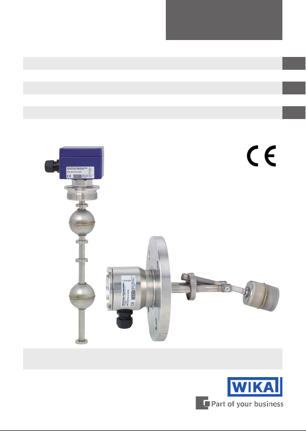
Magnetic operated float switches Model RSM and HIF
Schwimmer-Magnetschalter Typ RSM und HIF
Interrupteurs magnètiques à flotteur Type RSM et HIF
Magnetic operated float switch
Fig. left: Model RSM, Fig. right: Model HIF
GB
D
F
Page 2

Operating instructions magnetic operated float switches
GB
Model RSM and HIF Page 3-12
Betriebsanleitung Schwimmer-Magnetschalter
D
Typ RSM und HIF Seite 13-22
Mode d‘emploi interrupteurs magnètiques à flotteur
F
Type RSM et HIF Page 23-33
WIKA Operating instructions Magnetic operated float switches Model RSM and HIF
2
13333283.01 01/2010 GB/D/F
Page 3
Contents
Contents
Contents
1. Functional description 4
2. Area of application 4
3. Assembly 5
4. Electrical connection 6
5. Commissioning / function test 8
6. Maintenance 9
7. Notes 9
8. Technical data 10
9. Protective RC-Modules 11
WARNING!
Instructions for proper installation and use of magnetic
float switches. Disregard may lead to malfunction or destruction of reed contacts.
DANGER!
Instructions to avoid personal or property damage.
GB
ELECTRICAL INSTALLATIONS
Instructions for proper electrical installation.
WIKA Operating instructions magnetic operated float switches Model RSM and HIF
13333283.01 01/2010 GB/D/F
3
Page 4

1. Functional description / 2. Area of application
1. Functional description
Magnetic operated float switches operate according to the float
GB
principle with magnetic transmission. A reed contact built into the
slip pipe (5) or contact pipe (8) is activated by the magnetic field of a
permanent magnet on reaching a preset switching point. The permanent magnet is located in a float (7) which changes its height with
the level of the medium being monitored. The switching state of the
reed contact can be evaluated and processed by a series-connected
control unit.
The number and arrangement of the floats depends on the number
of preset switching points, their contacting function and the distance
apart of the switching points.
2. Area of application
Magnetic operated float switches are used exclusively for level
control and monitoring of liquid media.
The liquids may not be heavily contaminated and should not have
a tendency to crystallize. Make sure that the materials of the switch
(float, slip pipe) which come into contact with the medium being
monitored are suitably resistant.
WIKA Operating instructions Magnetic operated float switches Model RSM and HIF
4
13333283.01 01/2010 GB/D/F
Page 5

3. Assembly
3. Assembly
Versions for vertical installation (Fig. 1)
Install WIKA magnetic operated float switches according to their
model (flange or thread [3])
Use the screws and nuts suitable for the flange for flange models.
Fit a suitable gasket (4) for sealing. Make sure it is installed in the
right position. (max. deviation from the vertical ± 30°)
The float (7) must be removed before installation in openings with a
diameter smaller than the diameter of the float
Mark the position of the set collars (6) before removing
If top and bottom of the floats are not already marked, please do
so now
Replace the float inside the tank after installing the magnetic
operated float switch
Then fix the set collars (6) back in the same position
The number of floats and position of stop rings are dependent on
the switching positions and number of switch points
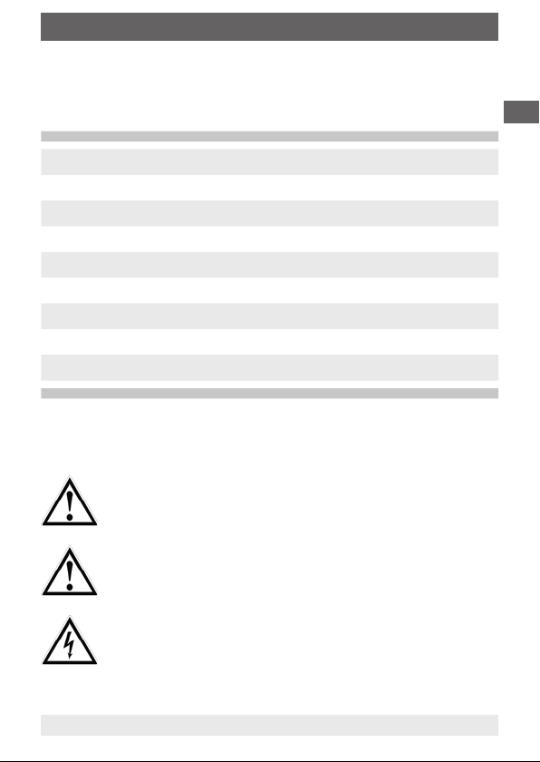
Versions for horizontal installation (Fig. 2)
Magnetic operated float switches for horizontal operation must be
installed as shown in figure 2.
Use the screws and nuts suitable for the flange for flange models. Fit
a suitable gasket (4) for sealing. Make sure it is installed in the right
position. (The float must be tilted downwards in the unactivated state).
When installing in the union, make sure that the tilting of the float is
not affected.
GB
WIKA Operating instructions magnetic operated float switches Model RSM and HIF
13333283.01 01/2010 GB/D/F
5
Page 6
3. Assembly / 4. Electrical connection
GB
When mounted inside ferromagnetic surroundings the
function could be restrained. This may cause a malfunction
and harm to goods.
The magnetic operated float switch must be mounted
outside ferromagnetic surroundings.
4. Electrical connection
When mounted inside ferromagnetic surroundings the
function could be restrained. This may cause a malfunction
and harm to goods.
The magnetic operated float switch must be mounted
outside ferromagnetic surroundings.
The electrical connection is made according to the wiring diagram
printed on the switch.
(Models with only one normally closed or normally open contact
contain no wiring diagram.)
The cable bushing (2) in the connection enclosure (1) must be sealed.
WIKA Operating instructions Magnetic operated float switches Model RSM and HIF
6
13333283.01 01/2010 GB/D/F
Page 7
4. Electrical connection
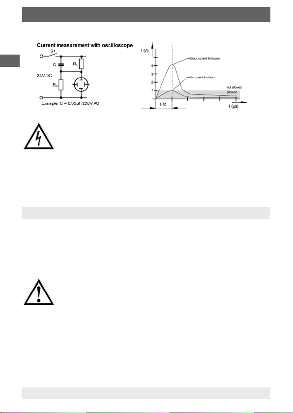
Use of magnetic float switches with inductive or capacitive
load may lead to the destruction of the reed switch. This
may cause a malfunction to the control circuitry and harm
to persons or goods.
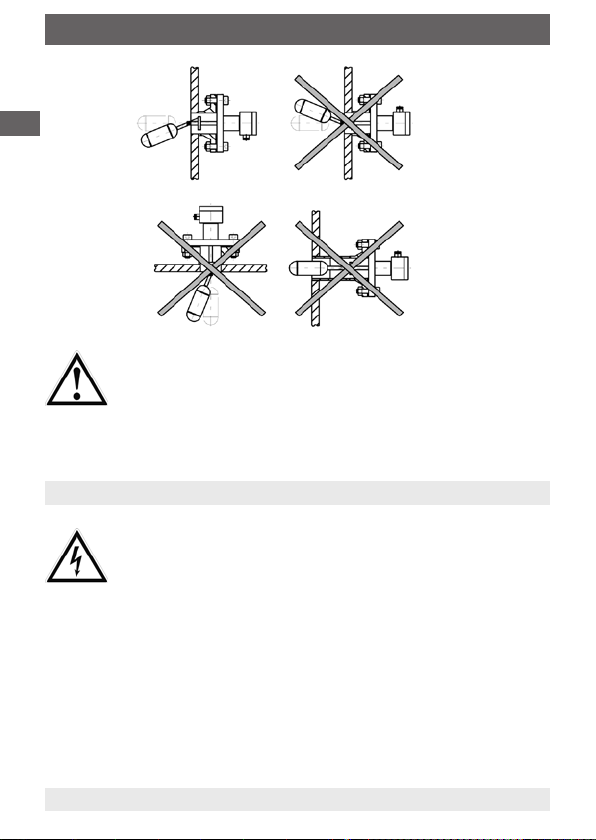
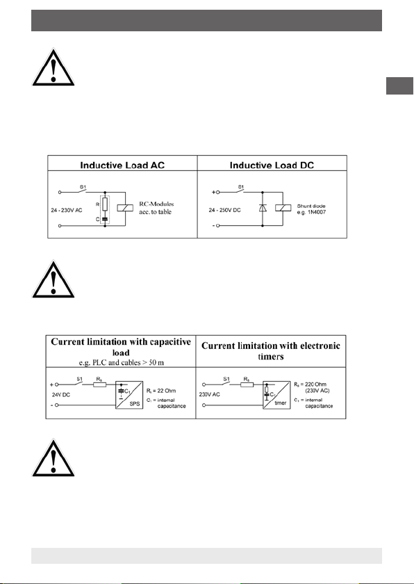
With inductive load, magnetic switches have to be
connected to a RC Network (acc. to appendix).
With capacitive load, connecting cables longer than
50 m or connection to a PLC with capacitive input circuit,
a 22 Ω resp. 47 Ω (10 VA contacts) resistor is required to be
connected in series to limit current spikes. A 220 Ω resistor
shall be used when connected to an electronic timer.
GB
Overloading the magnetic float switches may lead to
the destruction of the reed switch, which may cause a
malfunction to the control circuitry and harm to persons or
goods. The maximum switch capacity values given in the
chapter "Technical data" and the Technical bulletin must
not be exceeded.
WIKA Operating instructions magnetic operated float switches Model RSM and HIF
13333283.01 01/2010 GB/D/F
7
Page 8
4. Electrical connection / 5. Commissioning / function test
GB
Magnetic float switches with connecting cable including no protective earth may be live under fault
conditions. Touching the housing may cause harm to
persons or even be lethal. These switches must only
be used with protective low voltage acc. to VDE 0100
(f. e. use a WIKA contact protection relay) or have to be
mounted in such way, that the switch is earthed.
5. Commissioning / function test
Switch on the power supply to the connected control unit. Fill the
vessel and check the function of the switching points of the magnetoperated float switch. The function test can also be conducted
manually on the removed switch.
Make sure that the function test does not accidentally set
any processes in motion.
WIKA Operating instructions Magnetic operated float switches Model RSM and HIF
8
13333283.01 01/2010 GB/D/F
Page 9

6. Maintenance / 7. Notes
6. Maintenance
The magnetic operated float switches operate free of maintenance
and wear when used properly.
The switch must be eye-checked within the scope of the necessary
inspections under extreme operating conditions.
7. Notes
The reed contacts must be operated on intrinsically safe circuits when
operating in „e“ areas of zone 1 or 2.
Float switches made of plastic may not be used in the „e“ areas of
zone 1 or 2.
Do not operate float switches in the immediate vicinity of strong
electromagnetic fields (distance away at least 1 m).
The switching points of the magnetic operated float switches cannot
be adjusted.
Magnetic operated float switches can only be used in media to which
the material of the slip pipe and the float is resistant.
The switches may not be exposed to heavy mechanical stresses
(shock, bending, vibrations).
GB
WIKA Operating instructions magnetic operated float switches Model RSM and HIF
13333283.01 01/2010 GB/D/F
9
Page 10

8. Technical data
8. Technical data
Switching behaviour: Norm close / Norm open
GB
Max. voltage: 250 V AC / DC
Max. current: 2 A AC / 1 A DC
Max. power: 100 VA, cosφ >0,7 / 50 W
Switching behaviour: Change over
Max. voltage: 250 V AC / DC
Max. current: 1 A AC / 0,5 A DC
Max. power: 40 VA, cosφ > 0,7 / 20 W
Magnet operated Mini Float Switches
Switching behaviour: Norm close / Norm open
Max. voltage: 250 V AC / DC
Max. current: 0,5 A AC / 0,25 A DC
Max. power: 10 VA , cosφ > 0,7 / 5 W
WIKA Operating instructions Magnetic operated float switches Model RSM and HIF
10
13333283.01 01/2010 GB/D/F
Page 11
9. Protective RC-Modules
9. Protective RC-Modules
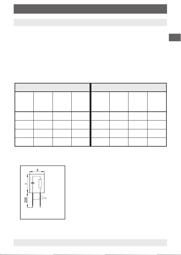
Please use RC-modules according to the table below. Rating of the
switches and supply voltage will determine the model to be used.
Other models might lead to destruction or lower service life of the
reed contacts.
For reed contacts 10-40 VA For reed contacts 40-100 VA
Capa-
citance
0,33 100 24 3/24 0,33 47 24 3/24
0,33 220 48 3/48 0,33 100 48 3/48
0,33 470 115 3/115 0,33 470 115 3/115
0,33 1500 230 3/230 0,33 1000 230 3/230
sistance
µF
Ohm
d = Ø16 ... Ø25 mm
I = 16 ... 58 mm
Re-
VoltageV~ModelACapa-
Wire
citance
µF
Re-
sistance
Ohm
VoltageV~Model
B
GB
WIKA Operating instructions magnetic operated float switches Model RSM and HIF
13333283.01 01/2010 GB/D/F
11
Page 12

GB
WIKA Operating instructions Magnetic operated float switches Model RSM and HIF
12
13333283.01 01/2010 GB/D/F
Page 13

Inhalt
Inhalt
Inhalt
1. Funktionsbeschreibung 14
2. Einsatzbereich 14
3. Montage 15
4. Elektrischer Anschluss 16
5. Inbetriebnahme / Funktionsprüfung 18
6. Wartung 19
7. Hinweise 19
8. Technische Daten 20
9. RC-Glieder zur Schutzbeschaltung 21
WARNUNG!
Hinweise zur fachgerechten Montage und den bestimmungsgemäßen Betrieb des Schwimmer-Magnetschalters.
Eine Nichtbeachtung kann zu Fehlfunktionen oder der
Zerstörung der Reedkontakte führen.
GEFAHR!
Hinweise zur Vermeidung von Personen- oder Sachschäden.
HINWEISE ZUR ELEKTRISCHEN INSTALLATION
Angaben für eine fachgerechte elektrische Installation.
D
WIKA Betriebsanleitung Schwimmer-Magnetschalter Typ RSM und HIF
13333283.01 01/2010 GB/D/F
13
Page 14

1. Funktionsbeschreibung / 2. Einsatzbereich
1. Funktionsbeschreibung
Schwimmer-Magnetschalter arbeiten nach dem Schwimmerprinzip
mit magnetischer Übertragung. Ein im Gleitrohr (5) bzw. Kontaktrohr (8) eingebauter Reedkontakt wird durch das Magnetfeld eines
D
Permanentmagneten bei Erreichen eines vorgegebenen Schaltpunktes
betätigt. Der Permanentmagnet befindet sich in einem Schwimmer (7),
der seine Höhenlage mit dem Pegel des zu überwachenden Mediums
verändert. Der Schaltzustand des Reedkontaktes kann durch eine
nachgeschaltete Steuereinrichtung ausgewertet und weiterverarbeitet
werden.
Die Anzahl und Anordnung der Schwimmer ist abhängig von der
Anzahl der vorgegebenen Schaltpunkte, deren Kontaktfunktion sowie
dem Abstand der Schaltpunkte.
2. Einsatzbereich
Schwimmer-Magnetschalter sind ausschließlich zur Füllstandssteuerung bzw. -überwachung von flüssigen Medien zu verwenden.
Die Flüssigkeiten dürfen keine starke Verschmutzungen oder Grobteile
aufweisen und nicht zum Auskristallisieren neigen. Es ist sicherzustellen, dass die medienberührenden Werkstoffe des Schalters (Schwimmer, Gleitrohr) gegen das zu überwachende Medium ausreichend
beständig sind.
14
WIKA Betriebsanleitung Schwimmer-Magnetschalter Typ RSM und HIF
13333283.01 01/2010 GB/D/F
Page 15

3. Montage
3. Montage
Ausführungen für vertikalen Einbau (Fig. 1)
WIKA Schwimmer-Magnetschalter entsprechend der Ausführung
(Flansch o. Gewinde [3]) einbauen
Bei Flanschausführungen sind die zum Flansch passenden Schrau-
ben und Muttern zu verwenden. Zum Abdichten ist eine geeignete
Dichtung (4) vorzusehen
Es ist auf korrekte Einbaulage zu achten. (max. Abweichung aus
der vertikalen ± 30°)
Bei Einbauöffnungen die kleiner als der Durchmesser des Schwim-
mers sind, ist der Schwimmer (7) vor dem Einbau des Schalters
abzunehmen
Die Position der Stellringe (6) ist vor dem Abnehmen zu markieren
(z. B. mit einem wasserfesten Stift)
Sofern die Schwimmer nicht gekennzeichnet sind, ist die Einbaula-
ge entsprechend zu kennzeichnen (z. B. „Oben“)
Nach dem Einbau des Schwimmer-Magnetschalters ist der
Schwimmer im Inneren des Tanks wieder aufzusetzen (Einbaulage
beachten!)
Die Stellringe (6) sind anschließend an den markierten Stellen
wieder zu befestigen
Die Anzahl der Schwimmer sowie die Position der Stellringe sind
vom Maß und der Anzahl der Schaltpunkte abhängig
Ausführungen für horizontalen Einbau (Fig. 2)
Schwimmer-Magnetschalter für horizontale Einbaulage sind gemäß
Fig. 2 einzubauen.
Bei Flanschausführungen sind die zum Flansch passenden Schrauben und Muttern zu verwenden. Zum Abdichten ist eine geeignete
Dichtung (4) vorzusehen. Es ist auf korrekte Einbaulage zu achten.
(Der Schwimmer muss im unbetätigten Zustand nach unten gekippt
sein). Beim Einbau in Stutzen muss gewährleistet sein, dass der
Schwimmer in seiner Kippbewegung nicht beeinträchtigt wird.
D
WIKA Betriebsanleitung Schwimmer-Magnetschalter Typ RSM und HIF
13333283.01 01/2010 GB/D/F
15
Page 16

3. Montage / 4. Elektrischer Anschluss
D
Beim Einbau in ferromagnetische Stutzen wird die Funktionsfähigkeit des Schalters beeinträchtigt. Gefahr von
Sachschäden durch fehlerhaftes Schaltverhalten des
Reedkontaktes.
Der Schwimmerschalter ist so einbauen, dass sich das
Kontaktrohr außerhalb eines ferromagnetischen Stutzens
befindet.
4. Elektrischer Anschluss
Der elektrische Anschluss ist entsprechend den im
Errichtungsland geltenden Errichtungsbestimmungen
durchzuführen und darf nur von Fachpersonal durchgeführt
werden.
Zur Erhöhung der Lebensdauer der Kontakte wird der
Betrieb an einem Kontaktschutzrelais empfohlen.
Der elektrische Anschluss ist entsprechend dem jeweiligen am
Schalter angebrachten Anschlussschema vorzunehmen.
(Ausführungen mit nur einem Öffner oder Schließerkontakt enthalten
kein Anschlussschema)
Die Kabeldurchführung (2) am Anschlussgehäuse (1) ist abzudichten
16
WIKA Betriebsanleitung Schwimmer-Magnetschalter Typ RSM und HIF
13333283.01 01/2010 GB/D/F
Page 17
4. Elektrischer Anschluss
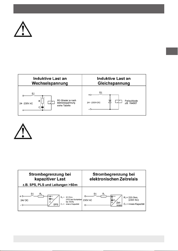
Der Betrieb der Schwimmer-Magnetschalter an induktiver
oder kapazitiver Last kann eine Zerstörung des Reedkontaktes zur Folge haben. Dies kann zu einer Fehlfunktion
der nachgeschalteten Steuerung und zu Personen- oder
Sachschäden führen.
Bei induktiver Belastung sind die Schwimmer-Magnetschalter durch Beschaltung mit einem RC-Glied gem.
Anhang bzw. einer Freilaufdiode zu schützen.
Bei kapazitiver Belastung, Leitungslängen über 50 m
oder dem Anschluss an Prozessleitsystemen mit kapazitivem Eingang ist zur Begrenzung des Spitzenstromes
ein Schutzwiderstand von 22 Ω bzw. 47 Ω (bei 10 VAKontakten) in Serie zu schalten.
Bei Anschluss an elektronische Zeitrelais muss ein Widerstand von 220 Ohm in Serie geschaltet werden.
D
WIKA Betriebsanleitung Schwimmer-Magnetschalter Typ RSM und HIF
13333283.01 01/2010 GB/D/F
17
Page 18

4. Elektrischer Anschluss / 5. Inbetriebnahme ...
Eine Überlastung des Schwimmer-Magnetschalters kann
eine Zerstörung des eingebauten Reedkontaktes zur Folge
haben. Dies kann zu einer Fehlfunktion der nachgeschalteten Steuerung und zu Personen- oder Sachschäden
führen. Die im Kapitel "Technische Daten" und im WIKA-
D
Datenblatt angegebenen Maximalwerte für die Schaltleistung sind einzuhalten.
Bei Schwimmer-Magnetschaltern mit Anschlusskabel ohne Schutzleiteranschluss kann der Schalter
im Fehlerfall spannungsführend sein. Bei Berührung
können schwere Körperschäden oder tödliche Verletzungen auftreten. Diese Schalter dürfen nur an Schutzkleinspannung nach VDE0100 betrieben werden (z.B.
an einem WIKA Kontaktschutzrelais) oder sind so zu
montieren, dass der Schwimmer-Magnetschalter mit
dem Potentialausgleich elektrisch verbunden ist.
5. Inbetriebnahme / Funktionsprüfung
Versorgungsspannung der angeschlossenen Steuerungseinrichtung
einschalten, Behälter füllen und die Schaltpunkte des SchwimmerMagnetschalters auf Funktion prüfen. Die Funktionsprüfung kann auch
manuell bei ausgebautem Schalter erfolgen.
Es ist sicherzustellen, dass durch die Funktionsprüfung
keine unbeabsichtigten Prozessabläufe eingeleitet werden.
18
WIKA Betriebsanleitung Schwimmer-Magnetschalter Typ RSM und HIF
13333283.01 01/2010 GB/D/F
Page 19

6. Wartung / 7. Hinweise
6. Wartung
Schwimmer-Magnetschalter arbeiten bei bestimmungsgemäßem
Gebrauch wartungs- und verschleißfrei.
Bei extremen Einsatzbedingungen sollte der Schalter im Rahmen der
durchzuführenden Revisionen einer Sichtkontrolle unterzogen werden.
7. Hinweise
Beim Betrieb im Ex-Bereich der Zone 1 oder 2 sind die
Reedkontakte an eigensicheren Stromkreisen zu betreiben.
Schwimmerschalter aus Kunststoff dürfen nicht im Ex-Bereich der
Zone 1 oder 2 eingesetzt werden.
Schwimmerschalter nicht in unmittelbarer Nähe von starken elektromagnetischen Feldern bzw. in unmittelbarer Nähe von Einrichtungen,
die durch Magnetfelder beeinflusst werden können, betreiben
(Abstand min. 1 m).
Die Schaltpunkte der Schwimmer-Magnetschalter können nicht
verstellt werden.
Schwimmer-Magnetschalter nur in Medien einsetzen gegen die der
Werkstoff des Gleitrohres und des Schwimmers beständig ist.
Die Schalter dürfen keinen starken mechanischen Belastungen (Stoß,
Verbiegen, Vibrationen) ausgesetzt werden.
D
WIKA Betriebsanleitung Schwimmer-Magnetschalter Typ RSM und HIF
13333283.01 01/2010 GB/D/F
19
Page 20

8. Technische Daten
8. Technische Daten
Kontaktfunktion: Öffner / Schließer
Max. Spannung: 250 V AC / DC
Schaltstrom: 2 A AC / 1 A DC
D
Schaltleistung: 100 VA, cosφ >0,7 / 50 W
Kontaktfunktion: Umschalter
Max. Spannung: 250 V AC / DC
Schaltstrom: 1 A AC / 0,5 A DC
Schaltleistung: 40 VA, cosφ > 0,7 / 20 W
Mini Schwimmerschalter
Kontaktfunktion: Öffner / Schließer
Spannung: 250 V AC / DC
Schaltstrom: 0,5 A AC / 0,25 A DC
Schaltleistung: 10 VA , cosφ > 0,7 / 5 W
20
WIKA Betriebsanleitung Schwimmer-Magnetschalter Typ RSM und HIF
13333283.01 01/2010 GB/D/F
Page 21

9. RC-Glieder zur Schutzbeschaltung
9. RC-Glieder zur Schutzbeschaltung
RC-Glieder sind, je nach Betriebsspannung, ausschließlich entsprechend untenstehender Tabelle zu verwenden.
Andere als die hier aufgeführten RC-Glieder führen zur Zerstörung
des Reedschalters.
Für Schutzgaskontakte von
10-40 VA
Kapa-
zität
µF
Wider-
stand
Ohm
Span-
nung
V~
TypAKapa-
0,33 100 24 3/24 0,33 47 24 3/24
0,33 220 48 3/48 0,33 100 48 3/48
0,33 470 115 3/115 0,33 470 115 3/115
0,33 1500 230 3/230 0,33 1000 230 3/230
Litze
d = Ø16 ... Ø25 mm
I = 16 ... 58 mm
Für Schutzgaskontakte von
40-100 VA
zität
µF
Wider-
stand
Ohm
Span-
nung
V~
Typ
B
D
WIKA Betriebsanleitung Schwimmer-Magnetschalter Typ RSM und HIF
13333283.01 01/2010 GB/D/F
21
Page 22

D
22
WIKA Betriebsanleitung Schwimmer-Magnetschalter Typ RSM und HIF
13333283.01 01/2010 GB/D/F
Page 23

Sommaire
Sommaire
Sommaire
1. Description du fonctionnement 24
2. Domaine d‘utilisation 24
3. Montage 25
4. Raccordement électrique 26
5. Mise en service / contrôle fonctionnel 29
6. Entretien 29
7. Remarques 30
8. Caractéristiques techniques 31
9. Circuits RC de protection de contacts 32
AVERTISSEMENT !
Instructions qui permettet le montage et l’utilisation correctes des régulateurs de niveau á flotteur. Un mépris de
ces instructions peut conduire au mauvais fonctionnement
ou á la detruction des contacts à lame souple.
DANGER !
Instructions qui permettet d’éviter de porter atteinte á des
personnes ou á des biens.
F
INSTALLATION ÉLECTRIQUE
Indications qui permettet une installation électrique
correcte.
WIKA Mode d‘emploi interrupteurs magnètiques à flotteur Type RSM et HIF
13333283.01 01/2010 GB/D/F
23
Page 24

1. Funktionsbeschreibung / 2. Einsatzbereich
1. Description fonctionnelle
Les interrupteurs magnétiques à flotteur fonctionnent suivant le principe des flotteurs à transfert magnétique. Un contact Reed logé dans
le tube de glissement (5) ou dans un tube de contact (8) est actionné
par le champ magnétique d‘un aimant permanent lorsqu‘un point de
commutation prédéterminé est atteint. L‘aimant permanent est monté
dans un flotteur (7) qui change sa position en hauteur avec le niveau
F
du milieu à surveiller. L‘état de commutation du contact Reed peut
être évalué et traité par un dispositif de commande monté en aval à
circuit de courant de commande à sécurité intrinsèque.
Le nombre et la disposition des flotteurs dépendent du nombre de
points de commutation prédéterminés et de leur fonction de contact
ainsi que de l‘écart des points de commutation.
2. Domaine d‘application
Les interrupteurs magnétiques à flotteur servent exclusivement
à commander ou à surveiller le niveau de remplissage de milieux
liquides.
Les liquides à surveiller ne doivent pas contenir de fortes pollutions
ou de particules grossières et ne doivent pas avoir tendance à se
cristalliser. Il faut s‘assurer que les matériaux de l‘interrupteur (flotteur,
tube de glissement) au contact du milieu résistent suffisamment au
milieu à surveiller.
WIKA Mode d‘emploi interrupteurs magnètiques à flotteur Type RSM et HIF
24
13333283.01 01/2010 GB/D/F
Page 25

3. Montage
3. Montage
Exécutions pour un montage à la verticale (fig. 1)
Monter les interrupteurs magnétiques à flotteur WIKA conformé-
ment à l‘exécution (bride ou filetage [3])
Pour les exécutions à bride, il convient d‘utiliser les vis et les
écrous adaptés à la bride. Pour étouper, il convient de prévoir un
joint adéquat (4)
Veiller à ce que la position de montage soit correcte. (Ecart
maximal par rapport à la verticale ± 30°)
En présence d‘ouvertures de montage plus petites que le dia-mètre
du flotteur, il convient d‘enlever le flotteur (7) avant le montage de
l‘interrupteur
Dans la mesure où les flotteurs ne portent pas de marquage, la
position de montage adéquate (par exemple en "haut") doit être
indiquée
Il convient de marquer la position des bagues de réglage (6) avant
l‘enlèvement
Après avoir monté l‘interrupteur magnétique à flotteur, il convient
de replacer le flotteur à l‘intérieur du réservoir
Les bagues de réglage (6) doivent être ensuite fixées de nouveau
au même endroit
Le nombre de flotteurs ainsi que la position des anneaux de règla-
ge dèpendent de la position et du nombre des contacts
Exécutions pour un montage à l‘horizontale (fig. 2)
Les interrupteurs magnétiques à flotteur destinés à un montage à
l‘horizontale doivent être montés conformément à la figure 2.
Pour les exécutions à bride, il convient d‘utiliser les vis et les écrous
adaptés à la bride. Pour étouper, il convient de prévoir un joint
adéquat (4). Veiller à ce que la position de montage soit correcte. (Le
flotteur doit être basculé vers le bas à l‘état non actionné).
Pour un montage dans des tubulures, il faut assurer que le flotteur ne
soit pas gêné dans son mouvement de basculement
F
WIKA Mode d‘emploi interrupteurs magnètiques à flotteur Type RSM et HIF
13333283.01 01/2010 GB/D/F
25
Page 26

1. Funktionsbeschreibung / 2. Einsatzbereich
F
Le montage dans des tubes ferromagnétiques entraîne
un mauvais fonctionnement du commutateur. Danger de
dommages matériels en raison de mauvaises commutations du contact reed.
Le commutateur du flotteur doit être monté de telle sorte
que la tubulure de contact se trouve à l‘extérieur d‘un tube
ferromagnétique.
4. Raccordement électrique
Il faut respecter les dispositions relatives aux installations électriques en vigueur dans le pays d‘exécution. Seul
le personnel spécialisé est autorisé à travailler sur les
installations électriques. our augmenter la durée de vie des
contacts, nous recommandons le fonctionnement avec un
relais de protection des contacts.
Le raccordement électrique doit être réalisé conformément au
schéma des connexions apposé sur l‘interrupteur.
(Les exécutions avec un seul contact d‘ouverture ou de fermeture
n‘ont pas de schéma des connexions.)
WIKA Mode d‘emploi interrupteurs magnètiques à flotteur Type RSM et HIF
26
13333283.01 01/2010 GB/D/F
Page 27

3. Montage
Il convient de s‘en tenir aux prescriptions en vigueur pour les installations électriques dans le pays d‘installation.
Il convient d‘étouper le passe-câble (2) sur le boîtier de raccordement
(1).
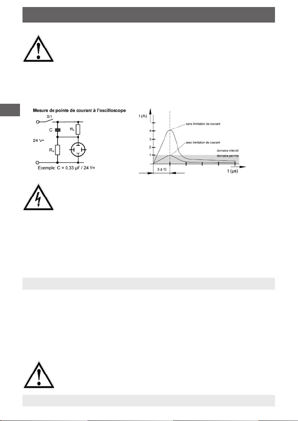
L‘utilisation des interrupteurs magnétiques á flotteur
sous charge inductive ou capacitive peut provoquer la
destruction du contact reed. Ceci peut entraîner le mauvais
fonctionnement de la commande située en aval ainsi que
des dommages corporels ou matériels.
Sous charge inductive, les interrupteurs magnétiques
doivent être protégés par un circuit RC (voir annexe) ou par
une diode de dérivation.
En cas de charge capacitive, de conduites de plus de 50
m de long ou de raccord à des systèmes d‘automatisme
industriel à entrée capacitive, il faut monter en série une
résistance protectrice de 22 ohms ou de 47 ohms (avec
des contacts de 10 VA) afin de limiter de courant de crête.
Une résistance de 220 Ohm montée en série doit être utilisée lors d’un raccordement à un minuteur éléctronique.
F
WIKA Mode d‘emploi interrupteurs magnètiques à flotteur Type RSM et HIF
13333283.01 01/2010 GB/D/F
27
Page 28
1. Funktionsbeschreibung / 2. Einsatzbereich
Une surcharge du commutateur magnétique peut provoquer la destruction du contact reed intégré. Ceci peut
entraîner le mauvais fonctionnement de la commande
située en avai ainsi que des dommages corporels ou
matériels. Il faut respecter les valeurs maximales de
puissance de rupture indiquée dans le chapitre „Données
techniques“ ainsi que dans la fiche technique WIKA.
F
Avec des interrupteurs magnétiques á flotteur à boîtier
métallique sans prise de terre, le boîtier peut être sous
tension en cas de perturbation. De graves lésions corporelles ou des blessures mortelles sont possibles en cas
de contact. Ces commutateurs ne peuvent être utilisés
qu‘avec une basse tension de protection selon VDE 0100
(WIKA relais de protection des contacts) ou bien doivent
être montés de telle sorte que le boîtier du interrupteur
magnétique á flotteur soit relié à une compensation de
potentiel.
5. Mise en service / contrôle fonctionnel
Mettre la tension d‘alimentation du dispositif de commande
raccordé en circuit. Remplir le réservoir et vérifier le fonctionnement
des points de commutation de l‘interrupteur magnétique à flotteur.
Le contrôle fonctionnel peut aussi être réalisé manuellement lorsque
l‘interrupteur est démonté. Ce faisant, il convient de veiller à ce
qu‘aucun déroulement de processus ne soit involontairement déclenché.
AVERTISSEMENT !
Il faut s‘assurer que le contrôle de fonctionnement ne
déclenche pas une étape de process involontaire.
WIKA Mode d‘emploi interrupteurs magnètiques à flotteur Type RSM et HIF
28
13333283.01 01/2010 GB/D/F
Page 29

3. Montage
6. Entretien
A condition d‘être utilisés de manière conforme, les interrupteurs
magnétiques à flotteur fonctionnent sans usure et ne nécessitent pas
d‘entretien.
En cas de conditions d‘utilisation extrêmes, l‘interrupteur devrait être
soumis à un contrôle visuel dans le cadre des révisions à réaliser.
7. Remarques
Pour une exploitation dans la zone explosive 1 ou 2, les contacts
Reed doivent être exploités sur des circuits de courant à sécurité
intrinsèque.
Les interrupteurs à flotteur en matière plastique n‘ont pas le droit
d‘être utilisés dans la zone explosive 1 ou 2.
Ne pas utiliser les interrupteurs à flotteur à proximité directe de
puissants champs électromagnétiques (distance minimale: 1 m).
Ne pas changer le positionnement des bagues de réglage ou ne pas
les enlever du tube de glissement.
Les points de commutation des interrupteurs magnétiques à flotteur
ne peuvent pas être déréglés.
Les interrupteurs magnétiques à flotteur ont uniquement le droit d‘être
utilisés dans des milieux contre lesquels le matériau du tube de glissement et du flotteur est résistant.
F
Les interrupteurs n‘ont pas le droit d‘être soumis à de fortes sollicitations mécaniques (chocs, torsion, vibration).
WIKA Mode d‘emploi interrupteurs magnètiques à flotteur Type RSM et HIF
13333283.01 01/2010 GB/D/F
29
Page 30

1. Funktionsbeschreibung / 2. Einsatzbereich
8. Caractéristiques techniques
Fonction de contact: ouverture / fermeture
Tension commutée: 250 V AC / DC
Courant commuté: 2 A AC / 1 A DC
Pouvoir de coupure: 100 VA, cosφ >0,7 / 50 W
Fonction de contact: inverseur
F
Tension commutée: 250 V AC / DC
Courant commuté: 1 A AC / 0,5 A DC
Pouvoir de coupure: 40 VA, cosφ > 0,7 / 20 W
Mini régulateurs de niveau
Fonction de contact: ouverture / fermeture
Tension commutée: 250 V AC / DC
Courant commuté: 0,5 A AC / 0,25 A DC
Pouvoir de coupure: 10 VA , cosφ > 0,7 / 5 W
WIKA Mode d‘emploi interrupteurs magnètiques à flotteur Type RSM et HIF
30
13333283.01 01/2010 GB/D/F
Page 31

3. Montage
9. Circuits RC de protection de contacts
Selon la tension d’alimentation, les circuits RC de protection de
contacts listés dans le tableau ci-dessous doivent être utilisés.
L’utilisation d’autres circuits RC conduit à la destruction des
contacts à lame souple.
F
Pour contacts à lame souple de
10 à 40 VA
Capa-
cité
µF
Rési-
stance
Ohm
Tensi-
on
V~
TypeACapa-
Pour contacts à lame souple de
40 à 100 VA
cité
µF
Rési-
stance
Ohm
Tensi-
on
V~
0,33 100 24 3/24 0,33 47 24 3/24
0,33 220 48 3/48 0,33 100 48 3/48
0,33 470 115 3/115 0,33 470 115 3/115
0,33 1500 230 3/230 0,33 1000 230 3/230
Fils de
raccordement
d = Ø16 ... Ø25 mm
I = 16 ... 58 mm
WIKA Mode d‘emploi interrupteurs magnètiques à flotteur Type RSM et HIF
13333283.01 01/2010 GB/D/F
Type
B
31
Page 32

F
WIKA Mode d‘emploi interrupteurs magnètiques à flotteur Type RSM et HIF
32
13333283.01 01/2010 GB/D/F
Page 33

Notes / Notizen / Notation
WIKA Betriebsanleitung Schwimmer-Magnetschalter Typ RSM und HIF
13333283.01 01/2010 GB/D/F
3333
Page 34

WIKA Global
Europe
Austria
WIKA Messgerätevertrieb Ursula
Wiegand GmbH & Co. KG, 1230 Wien
Phone: (+43) 1-86 91 631
E-mail: info@wika.at
www.wika.at
Benelux
WIKA Benelux, 6101 WX Echt
Phone: (+31) 475-535 500
E-mail: info@wika.nl
www.wika.nl
Bulgaria
WIKA Bulgaria EOOD, 1309 Sofia
Phone: (+359) 2 82138-10
E-mail: t.antonov@wika.bg
Finland
WIKA Finland Oy, 00210 Helsinki
Phone: (+358) 9-682 49 20
E-mail: info@wika.fi
www.wika.fi
France
WIKA Instruments s.a.r.l.
95610 Eragny-sur-Oise
Phone: (+33) 1-34 30 84 84
E-mail: info@wika.fr
www.wika.fr
Germany
WIKA Alexander Wiegand SE & Co. KG
63911 Klingenberg
Phone: (+49) 93 72-13 20
E-mail: info@wika.de
www.wika.de
Italy
WIKA Italia Srl & C. sas
20020 Arese (Milano)
Tel. (+39) 02 9386-11
Fax: (+39) 02 9386-174
E-Mail: info@wika.it
www.wika.it
34
WIKA Betriebsanleitung Schwimmer-Magnetschalter Typ RSM und HIF
Poland
WIKA Polska S.A., 87-800 Wloclawek
Phone: (+48) 542 30 11 00
E-mail: info@wikapolska.pl
www.wikapolska.pl
Romania
WIKA Instruments S.R.L., Bucuresti
Phone: (+40) 21-456 31 38
E-mail: m.anghel@wika.ro
Russia
ZAO WIKA MERA, 127015 Moscow
Phone: (+7) 495-648 01 80
E-mail: info@wika.ru
www.wika.ru
Serbia
WIKA Merna Tehnika d.o.o.
11060 Belgrade
Phone: (+381) 11 27 63 722
E-mail: info@wika.co.yu
www.wika.co.yu
Spain
Instrumentos WIKA, S.A.
08280 Sabadell (Barcelona)
Phone: (+34) 90-290 25 77
E-mail: info@wika.es
www.wika.es
Switzerland
MANOMETER AG
6285 Hitzkirch
Phone: (+41) 41-919 72 72
E-mail: info@manometer.ch
www.manometer.ch
Ukraine
WIKA Pribor GmbH, 83016 Donetsk
Phone: (+38) 062 345 34 16
E-mail: info@wika.donetsk.ua
www.wika.donetsk.ua
13333283.01 01/2010 GB/D/F
Page 35

WIKA Global
United Kingdom
WIKA Instruments Ltd
Merstham, Redhill RH13LG
Phone: (+44) 17 37 64 40 08
E-mail: info@wika.co.uk
www.wika.co.uk
North America
Canada
WIKA Instruments Ltd., Head Office
Edmonton, Alberta, T6N 1C8
Phone: (+1) 780-463 70 35
E-mail: info@wika.ca
www.wika.ca
Mexico
Instrumentos
Phone: (+52) 555 020 53 00
E-Mail ventas@wika.com.mx
www.wika.com.mx
USA
WIKA Instrument Corporation
Lawrenceville, GA 30043
Phone: (+1) 770-513 82 00
E-mail: info@wika.com
www.wika.com
South America
Argentina
WIKA Argentina S.A., Buenos Aires
Phone: (+54-11) 4730 18 00
E-mail: info@wika.com.ar
www.wika.com.ar
Brazil
WIKA do Brasil Ind. e Com. Ltda.
CEP 18560-000 Iperó - SP
Phone: (+55) 15-3266 16 55
E-mail: marketing@wika.com.br
www.wika.com.br
WIKA Betriebsanleitung Schwimmer-Magnetschalter Typ RSM und HIF
13333283.01 01/2010 GB/D/F
WIKA Mexico S.A. de C.V.
Africa/Middle East
Egypt
WIKA Alexander Wiegand GmbH &
Co. KG
Nasr City, Cairo
Phone: (+20) 2 2287 6219
E-mail: ahmed.azab@wika.de
South Africa
WIKA Instruments (Pty.) Ltd.
Gardenview, Johannesburg 2047
Phone: (+27) 11-621 00 00
E-mail: sales@wika.co.za
www.wika.co.za
United Arab Emirates
WIKA Middle East FZE
Jebel Ali, Dubai
Phone: (+971) 4 - 883 9090
E-mail: wikame@emirates.net.ae
Asia
China
WIKA International Trading
(Shanghai) Co., Ltd.
Phone: (+86) 21 - 5385 2573
E-mail: info@wika.com.cn
www.wika.com.cn
India
WIKA Instruments India Pvt. Ltd.
Village Kesnand, Wagholi
Pune - 412 207
Phone: (+91) 20 - 6629 3200
E-mail: sales@wika.co.in
www.wika.co.in
Japan
WIKA Japan K. K.
Tokyo 105-0023
Phone: (+81) 3-54 39 66 73
E-mail: t-shimane@wika.co.jp
3535
Page 36

WIKA Global
Kazakhstan
TOO WIKA Kazakhstan
050050 Almaty
Phone: (+7) 32 72 33 08 48
E-mail: info@wika.kz
Korea
WIKA Korea Ltd.
Seoul 153-023
Phone: (+82) 2 - 8 69 05 05
E-mail: info@wika.co.kr
Malaysia
WIKA Instrumentation (M) Sdn. Bhd.
Selangor Darul Ehsan
Phone: (+60) 3 - 56 36 88 58
E-mail: info@wika.com.my
www.wika.com.my
Weitere WIKA Niederlassungen weltweit finden Sie online unter www.wika.de.
Further WIKA subsidiaries worldwide can be found online at www.wika.de.
La liste des autres filiales WIKA dans le monde se trouve sur www.wika.de
Technical alteration rights reserved.
Technische Änderungen vorbehalten.
Sous réserve de modifications techniques.
Singapore
WIKA Instrumentation Pte. Ltd.
569625 Singapore
Phone: (+65) 68 44 55 06
E-mail: info@wika.com.sg
www.wika.com.sg
Taiwan
WIKA Instrumentation Taiwan Ltd.
Pinjen, Taoyuan
Phone: (+886) 034 20 60 52
E-mail: info@wika.com.tw
www.wika.com.tw
Turkey
WIKA Alexander Wiegand GmbH &
Co. KG
Türkiye irtibat bürosu
Maltepe - Istanbul
Phone: (+90) 216/305 4624
h.kizilkaya@wika.com.tr
http://www.wika.com.tr
WIKA Alexander Wiegand SE & Co. KG
Alexander-Wiegand-Straße 30
63911 Klingenberg • Germany
Tel (+49) 93 72/132-0
Fax (+49) 93 72/132-406
E-Mail info@wika.de
www.wika.de
36
WIKA Betriebsanleitung Schwimmer-Magnetschalter Typ RSM und HIF
13333283.01 01/2010 GB/D/F
 Loading...