

Page 1
Operating instructions
Betriebsanleitung
Mode d'emploi
Manual de instrucciones
EN
DE
FR
ES
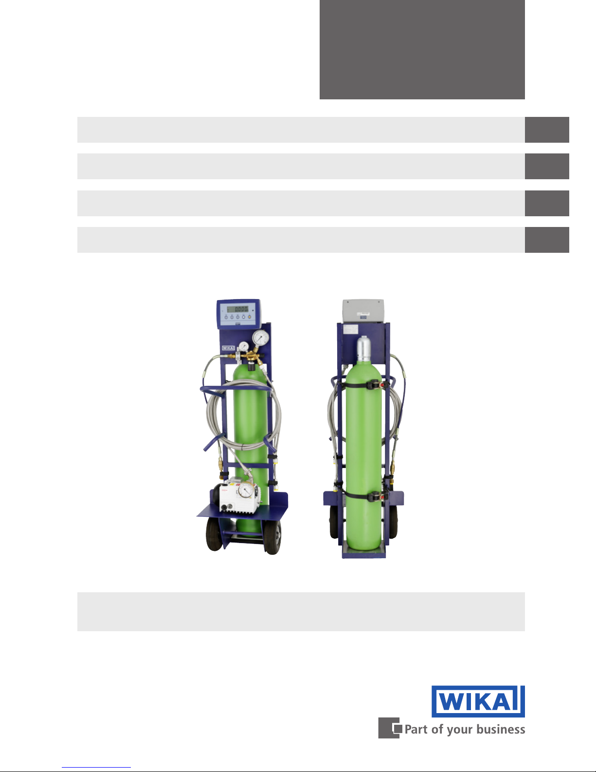
SF₆ gas filling cart, model GFU08
SF₆-Gas Füllwagen, Typ GFU08
Chariot de remplissage de gaz SF₆, type GFU08
Carro de servicio para gas SF₆, modelo GFU08
SF₆ gas filling cart, model GFU08
Page 2

2
14033074.01 11/2018 EN/DE/FR/ES
WIKA operating instructions SF₆ gas filling cart, model GFU08
EN
DE
FR
ES
Operating instructions model GFU08 Page 3 - 38
Betriebsanleitung Typ GFU08 Seite 39 - 74
Mode d'emploi type GFU08 Page 75 - 110
Manual de instrucciones modelo GFU08
Página 111 -146
© 11/2018 WIKA Alexander Wiegand SE & Co. KG
All rights reserved. / Alle Rechte vorbehalten.
WIKA
®
is a registered trademark in various countries.
WIKA
®
ist eine geschützte Marke in verschiedenen Ländern.
Prior to starting any work, read the operating instructions!
Keep for later use!
Vor Beginn aller Arbeiten Betriebsanleitung lesen!
Zum späteren Gebrauch aufbewahren!
Lire le mode d‘emploi avant de commencer toute opération !
A conserver pour une utilisation ultérieure !
¡Leer el manual de instrucciones antes de comenzar cualquier trabajo!
¡Guardar el manual para una eventual consulta!
Page 3

3
WIKA operating instructions SF6 gas lling cart, model GFU08
14033074.01 11/2018 EN/DE/FR/ES
EN
Contents
1. General information 4
2. Safety 5
3. Specications 16
4. Design and function 18
5. Transport, packaging and storage 19
6. Commissioning, operation 20
7. Display unit 24
8. Instrument messages during operation 33
9. Maintenance and cleaning 35
10. Faults 36
11. Dismounting and disposal 38
Contents
Page 4

4
WIKA operating instructions SF6 gas lling cart, model GFU08
14033074.01 11/2018 EN/DE/FR/ES
EN
1. General information
1. General information
■
The SF6 gas lling cart described in the operating instructions has been designed
and manufactured using state-of-the-art technology.All components are subject to
stringent quality and environmental criteria during production. Our management
systems are certied to ISO 9001 and ISO 14001.
■
These operating instructions contain important information on handling the
instrument. Working safely requires that all safety instructions and work instructions
are observed.
■
Observe the relevant local accident prevention regulations and general safety
regulations for the instrument’s range of use.
■
The operating instructions are part of the product and must be kept in the immediate
vicinity of the instrument and readily accessible to skilled personnel at any time.
■
Skilled personnel must have carefully read and understood the operating instructions
prior to beginning any work.
■
The manufacturer's liability is void in the case of any damage caused by using
the product contrary to its intended use, non-compliance with these operating
instructions, assignment of insuciently qualied skilled personnel or unauthorised
modications to the instrument.
■
The general terms and conditions contained in the sales documentation shall apply.
■
Subject to technical modications.
■
Further information:
- Internet address: www.wika.de/sf6, www.wika.com/sf6
- Relevant data sheet: SP 63.08
- Application consultant:
Tel.: (+49) 9372/132-8971
E-mail: sf6-sales@wika.de
Page 5

5
WIKA operating instructions SF6 gas lling cart, model GFU08
14033074.01 11/2018 EN/DE/FR/ES
EN
2. Safety
2. Safety
2.1 Importance of these operating instructions
■
These operating instructions contain important information on handling the SF6 gas
lling cart. Working safely requires that all safety instructions and work instructions
are observed. Non-compliance can lead to hazardous situations.
■
Pass the operating instructions on to the next operator or owner of the SF6 gas lling
cart.
■
Before any operation, the operator must ensure that personnel have carefully read
the operating instructions and material safety data sheets.
■
The safety instructions relevant for the task can be found at the start of the respective
chapters (e.g. transport, commissioning, ...)
2.2 Explanation of symbols
DANGER!
... indicates a directly dangerous situation resulting in serious injury or
death, if not avoided.
DANGER!
... identies hazards caused by electrical power. Should the safety
instructions not be observed, there is a risk of serious or fatal injury.
WARNING!
... indicates a potentially dangerous situation that can result in serious
injury or death, if not avoided.
CAUTION!
... indicates a potentially dangerous situation that can result in light
injuries or damage to property or the environment, if not avoided.
Information
... points out useful tips, recommendations and information for ecient
and trouble-free operation.
Page 6

6
WIKA operating instructions SF6 gas lling cart, model GFU08
14033074.01 11/2018 EN/DE/FR/ES
EN
2. Safety
Handling instructions
2. 3. Sequence of operations
Handling instructions must be carried out in the specied order.
▶
Handling instructions
Handling instructions without specied order.
⇒
Result
Describes the result of an operation.
→ Cross reference
Refers to another section in the operating instructions.
2.3 Intended use
The instrument has been designed and built solely for the intended use described here,
and may only be used accordingly. The manufacturer shall not be liable for claims of any
type based on operation contrary to the intended use.
Intended use
The SF
6
gas filling cart is used for filling and refilling SF6 gas into gas-tight tanks
provided and authorised for this purpose. The filling pressure can be set on the built-in
pressure reducer.
The model GFU08-W and GFU08-C SF
6
gas filling carts include, in addition, scales for
the measurement of the transferred mass of SF
6
gas.
Model GFU08-E or GFU08-C includes an additional vacuum pump, with which the gas
compartment can be evacuated before filling it.
Make sure that the vacuum pump is only used to pump out the air and not the SF
6
gas.
Application areas
Only use the SF₆ gas filling cart in applications that lie within its technical performance
limits (e.g. max. ambient temperature, material compatibility, ...).
→ For performance limits see chapter 3 “Specifications”.
The SF₆ gas filling cart is suitable for indoor and outdoor use. For safe operation, the
installation location must fulfil the following requirements:
■
Installation location is always supervised by skilled personnel or is not openly
accessible.
■
The foundation must be horizontal and level.
■
Non-explosive atmosphere.
■
Atmosphere must not be corrosion-inducing.
■
The atmosphere must not contain high levels of dust.
■
No operation outdoors during rain or electrical storms (IP20).
■
The installation location must offer sufficient space to enable safe operation.
Operating and maintenance personnel must be able to move freely around the
instrument.
■
The maximum permissible ambient temperature must not be exceeded.
Page 7

7
WIKA operating instructions SF6 gas lling cart, model GFU08
14033074.01 11/2018 EN/DE/FR/ES
EN
2. Safety
SF6 gas filling cart with scales (model GFU08-W or GFU08-C):
■
Handle electronic components with the required care (protect from humidity, impacts,
strong magnetic elds, static electricity and extreme temperatures, do not insert any
objects into the instrument or its openings). Plugs and sockets must be protected
from contamination.
■
If the instrument is transported from a cold into a warm environment, the formation
of condensation may result in instrument malfunction. Before putting it back into
operation, wait for the instrument temperature and the room temperature to equalise.
The technical specifications contained in these operating instructions must be
observed. Improper handling or operation of the instrument outside of its technical
specifications requires the instrument to be taken out of service immediately and
inspected by an authorised WIKA service engineer.Unauthorised alterations by the
operator are not permitted, especially on safety devices. Unauthorised alterations could
result in the improper functioning of safety equipment and result in life-threatening
situations.
WIKA is not liable for changes made by persons who have not been authorised by WIKA.
The manufacturer shall not be liable for claims of any type based on operation contrary
to the intended use.
Technical restrictions
The technical specications contained in these operating instructions must be
observed. Improper handling or operation of the instrument outside of its technical
specications requires the instrument to be taken out of service immediately and
inspected by an authorised WIKA service engineer.Technical specications:
→ Siehe Kapitel 3 “Specications”.
2.4 Responsibility of the operator
The instrument is used in the industrial sector. The operator is therefore responsible for
legal obligations regarding safety at work.
The safety instructions within these operating instructions, as well as the safety, accident
prevention and environmental protection regulations for the application area must be
maintained.
The operator is obliged to maintain the product label in a legible condition.
To ensure safe working on the instrument, the operating company must ensure
■
that suitable first-aid equipment is available and aid is provided whenever required.
■
that the operating personnel are regularly instructed in all topics regarding work
safety, first aid and environmental protection and know the operating instructions and
in particular, the safety instructions contained therein.
■
that the instrument is suitable for the particular application in accordance with its
intended use.
■
that personal protective equipment is available.
Page 8

8
WIKA operating instructions SF6 gas lling cart, model GFU08
14033074.01 11/2018 EN/DE/FR/ES
EN
2. Safety
2.5 Personnel qualification
All work on and with the SF
6
gas filling cart should only be carried out by trained and
authorised personnel.Observe the applicable national regulations, especially with
respect to hazardous materials and the qualification of personnel.
For training please contact the application consultant.
Tel.: +49 9372 132-0
Fax: +49 9372 132-406
Transport
Observe the applicable national regulations, especially with respect to hazardous
materials and the qualication of personnel.
Operation
Observe the applicable national regulations, especially with respect to hazardous
materials and the qualication of personnel.
In Europe, operating personnel must be qualied in accordance with the following
regulations:
■
F-gas regulation (EU) 517/2014
■
Regulation (EC) 305/2008
Maintenance
The maintenance tasks described in these operating instructions must only be carried
out by personnel who have been authorised by the operator. Maintenance tasks which
are described in the operating instructions of sub-components should be carried out in
accordance with their specications and instructions.
Use in high-voltage plants
The plant operator must ensure that the handling of SF₆ gas is only carried out by
a qualified company or by qualified persons who have been specifically trained in
accordance with IEC 61634, section 4.3.1 or IEC 60480, section 10.3.1.
In the European Union, any activity related to fluorinated greenhouse gases must be
carried out by certified skilled personnel. The certification must be made in accordance
with Regulation (EC) No. 305/2008.
2.6 Additional safety instructions for use in switchgear
The operator must ensure that the SF
6
gas is handled by a company qualified for this or
by employees trained in accordance with IEC 61634 chapter 4.3.1 and IEC 60480
chapter 10.3.1.
Valid standards for SF
6
gas
■
Installation, construction, commissioning:
IEC 61634 (handling of SF
6
),
IEC 60376 (new SF
6
, technical SF6),
IEC 60480 (used SF
6
),
CIGRE report 276, 2005 (Practical SF
6
handling instructions)
Page 9

9
WIKA operating instructions SF6 gas lling cart, model GFU08
14033074.01 11/2018 EN/DE/FR/ES
EN
2. Safety
■
Leakages during operation:
IEC 60376 (new SF
6
, technical SF6),
IEC 60480 (used SF
6
),
CIGRE 2002 (“SF
6
in the Electric Industry”)
■
Repairs and maintenance:
IEC 61634 (Use and handling of SF
6
in high-voltage switchgear and control gear),
CIGRE 1991 (Handling of SF6),
CIGRE report 276, 2005 (Practical SF
6
handling instructions),
CIGRE report 163, 2000 (Guide for SF6 gas mixtures)
SF
6
is a colourless and odourless, chemically neutral, inert and
non-ammable gas which is approx. 5 times heavier than air, not toxic
and not harmful to the ozone layer. Detailed information is given in
IEC 60376 and IEC 61634.
2.7 Personal protective equipment
The personal protective equipment is designed to protect the personnel from hazards
that could impair their safety or health during work. When carrying out the various
tasks on and with the SF
6
gas filling cart, the personnel must wear personal protective
equipment.The personal protective equipment specified here is related exclusively
to the product described. Further requirements which arise from the environmental
conditions at the place of use, other products or linking with other products have not
been taken into consideration here.The requisite personal protective equipment must be
provided by the operating company.
The operator is in no way relieved of his obligations under labour law for the safety and
the protection of workers' health.
The design of the personal protective equipment must take into account all operating
parameters of the place of use.
For a safe handling of the SF
6
gas filling cart, the following personal protective
equipment is required:
Safety shoes
The safety shoes must be worn over the entire period when working on
gas containers (e.g. gas cylinders, tanks). The safety shoes protect the
feet from falling items and liquid splashes.
Safety goggles
The safety goggles must be worn over the entire period when working on
hoses or gas containers (e.g. gas cylinders, tanks).
The safety goggles protect the eyes from any flying particles, escaping
gas and liquid splashes.
Page 10

10
WIKA operating instructions SF6 gas lling cart, model GFU08
14033074.01 11/2018 EN/DE/FR/ES
EN
2. Safety
Protective gloves
Based on the gas properties, it is possible that the gas, due to the quick
expansion, gets very cold if the cylinder is opened very quickly.
Wear protective gloves to protect from freezing.
If, with an operator risk analysis, contaminated gases should be detected, for
any subsequent maintenance operations, protective measures appropriate to the
contamination should be taken.
Respirator
For maintenance work, the respirator must correspond to the protection
level specified for the corresponding gas in the material safety data sheet.
Protective suit
For maintenance operations, specific protective clothing must be worn
during the entire duration. The protective clothing protects the body from
contaminated SF₆ gas. The operator must select the specific protective
clothing correspondingly.
General safety instructions
Contents of the general safety instructions
This chapter deals with the general safety in the handling of SF
6
gas and the SF6 gas
lling cart. The safety instructions relevant for the task can be found at the start of the
respective chapters (e.g. transport, commissioning, ...) and must be followed.
Handling SF₆ gas
SF₆ gas is a greenhouse gas which is listed in the Kyoto Protocol. SF6 gas must not be
released into the atmosphere, but must be collected in suitable containers.
Properties of SF6 gas
■
Colourless and odourless
■
Chemically neutral
■
Inert
■
Not flammable
■
Five times heavier than air
■
Non-toxic
■
No damage to the ozone layer
Detailed information is given in IEC 60376 and IEC 61634.
Risk of asphyxiation through SF6 gas
High concentrations of SF₆ gas can lead to asphyxiation, since breathable air is
displaced from the lungs with the inhalation of SF₆ gas.Since SF₆ gas is heavier than air,
it collects, especially, at ground level or lower-lying rooms below the reference level (e.g.
cellars). This is particularly dangerous since SF6 gas is colourless and odourless and
thus may be imperceptable to people.
Page 11

11
WIKA operating instructions SF6 gas lling cart, model GFU08
14033074.01 11/2018 EN/DE/FR/ES
EN
2. Safety
Danger caused by decomposition products
SF₆ gas in electrical systems may contain decomposition products generated by electric
arcs:
■
Gaseous sulphur fluoride
■
Sulphur hexafluoride
■
Solid and atomized metal fluorides, metal sulfides, metal oxides
■
Hydrogen fluoride
■
Sulphur dioxide
Decomposition products can be harmful to health.
■
They can cause poisoning by inhalation, ingestion or contact with the skin.
■
They may be irritating to the eyes, the respiratory system or the skin and burn them.
■
Inhalation of large quantities may damage the lungs.
Observe the following safety instructions in order to avoid danger from SF₆ gas:
■
Wear personal protective equipment.
■
Read the material safety data sheet of the gas supplier.
■
Ensure good ventilation.
■
Ensure the leak tightness of the equipment with a gas detector (e.g. model GIR-10).
Use of accessories and spare parts
It is recommended to use original accessories and original spare parts from WIKA.
Using accessories and spare parts from third parties can lead to damage to the
instrument or accidents, due to quality defects or other reasons.WIKA assumes no
liability for damage or accidents caused by a malfunction or unsuitability of accessories
and spare parts which do not originate from WIKA (e.g. unsealed connecting parts). No
guarantee claims can be made which arise due to a malfunction or unsuitability of any
accessory or spare part from a third party.
Danger of tripping due to improper installation of connections
Improperly installed connections such as cables, hoses or pipelines can create tripping
hazards, and can cause serious injury.
Route the connections so that no tripping sources are present. Mark unavoidable
tripping sources with yellow and black marker tape.
2.8 Residual risks
What are residual risks?
The instrument has been designed so that no personnel are exposed to preventable
risks. Particular hazard points are protected through specific protective systems.
In the operating instructions, the safety instructions refer to these hazard points and the
necessary behaviour of the personnel in order to minimise risks arising from the hazard
points.
Page 12

12
WIKA operating instructions SF6 gas lling cart, model GFU08
14033074.01 11/2018 EN/DE/FR/ES
EN
2.9 Regular safety inspection
The operator is responsible for checking the instrument at least once a year or after
specific incidents. The checking should only be carried out by authorised and trained
personnel from WIKA or WIKA partner companies.
At the same time, a complete testing of the technical condition with respect to accident
safety must be carried out. In addition, the instrument, including all components, must
be thoroughly examined for damage.
The operator must ensure the immediate rectification of defects.
2. Safety
Page 13

13
WIKA operating instructions SF6 gas lling cart, model GFU08
14033074.01 11/2018 EN/DE/FR/ES
EN
2. Safety
2.10 Special hazards
DANGER!
Danger to life caused by electric current
Upon contact with live parts, there is a direct danger to life.
■
The instrument may only be installed and mounted by skilled
personnel.
■
Operation using a defective power supply unit (e.g. short circuit from
the mains voltage to the output voltage) can result in life-threatening
voltages at the instrument!
WARNING!
■
The wetted parts have been designed exclusively for SF6 gas or, if an
adapter (available as an option) is used, also for N
2
.
■
The lines with mounted lling hose are pre-lled with SF6 gas. The
pressure of the transport lling is approx. 200 mbar (2.9 psi) SF
6
gas.
Models GFU08-E, GFU08-C
WARNING!
■
Only skilled electrical personnel are allowed to wire electrical
connections
■
After a correct commissioning, the SF6 gas lling cart should only be
moved in the upright position. Otherwise oil may leak out of the case.
■
For evacuation using the vacuum pump, only use the hose delivered
with the unit
■
Do not operate the SF6 gas lling cart in the rain or in a damp
environment
■
Check the oil level of the vacuum pump at regular intervals and adjust
it, if necessary
■
Do not use the vacuum pump to pump out SF6 gas
Page 14

14
WIKA operating instructions SF6 gas lling cart, model GFU08
14033074.01 11/2018 EN/DE/FR/ES
EN
2. Safety
Date of manufacture
Model GFU08-E: Filling cart with vacuum pump
Date of manufacture
■
To accelerate the lling process from the SF6 gas cylinder, the SF6 gas
cylinder can be heated up. Only use an appropriate cylinder heater.
■
To check the leak tightness of the cylinder connection, an SF6 gas leak
detector, e.g. model GIR-10, should be used at regular intervals
■
For the models GFU08-E and GFU08-C, an appropriate vacuum pump
oil (see operating instructions of the vacuum pump) must be stocked
up in order to maintain the required oil level by lling it up, if necessary.
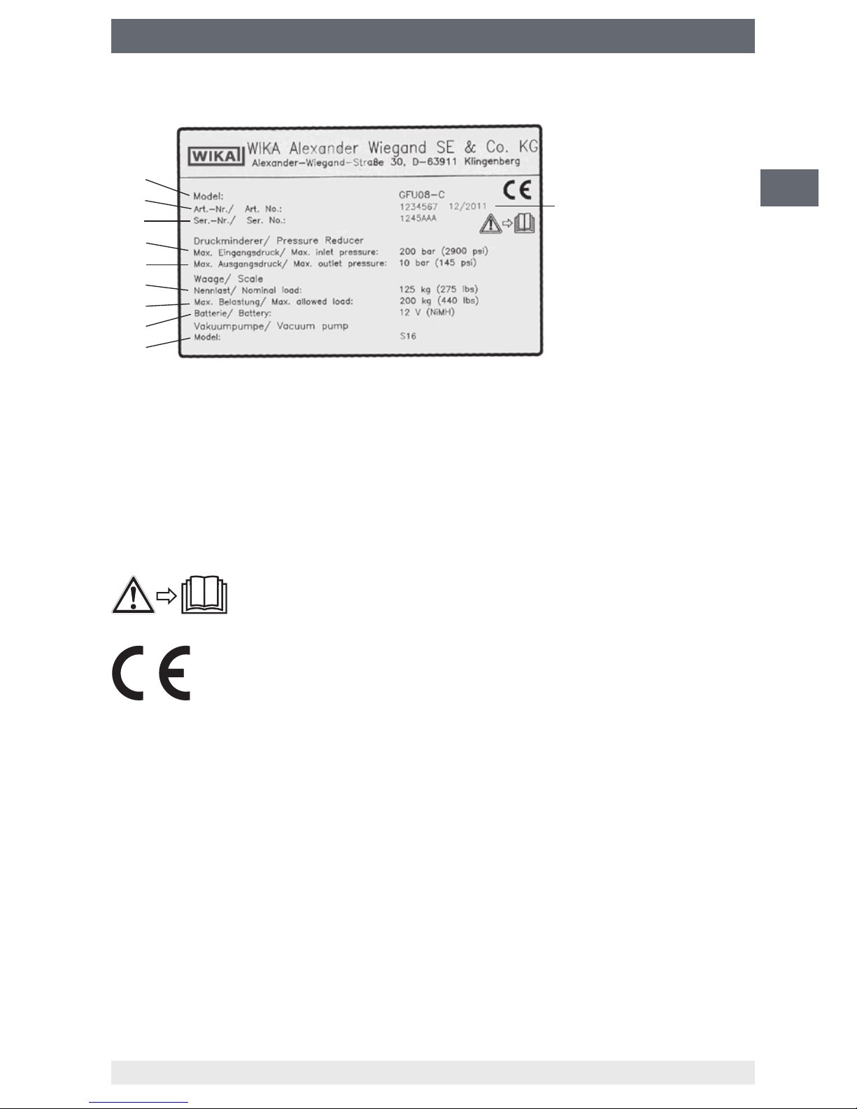
2.11 Labelling / Safety marks
Product label model GFU08-B:
Model GFU08-W lling cart: Filling cart with scales
Model GFU08-C: Filling cart with scales and vacuum pump
Date of manufacture
Page 15
15
WIKA operating instructions SF6 gas lling cart, model GFU08
14033074.01 11/2018 EN/DE/FR/ES
EN
2. Safety
Model description Scales:
Article number
Rated load
Serial number
Maximum loading
Pressure reducer:
Battery type
Maximum input pressure Vacuum pump:
Maximum output pressure
Model description
Date of manufacture
Explanation of symbols
Before mounting and commissioning the instrument, ensure you
read the operating instructions!
CE, Communauté Européenne
Instruments bearing this mark comply with the relevant European
directives.
Page 16

16
WIKA operating instructions SF6 gas lling cart, model GFU08
14033074.01 11/2018 EN/DE/FR/ES
EN
3. Specications
3. Specifications
Filling cart
Gas cylinder
connection
W 21.8 x 1/14" connector DIN 477 (others optional)
Connecting hose with bend protection; length 0.8 m (31.5")
Max. initial pressure 200 bar (2,900 psi)
Max. output pressure 10 bar (145 psi)
Gas cylinder tie-down 2 x self-storing ratchet strap 25 mm x 1.8 m (1" x 70"); marked per
EN 12195-2 for holding 250 daN each
optionally with chain
Filling hose 6 m (235") wire-braided stainless steel hose with DN 8 self-sealing
valves; other lengths optional
Rubber wheels Solid rubber 250 x 60 mm (9.8" x 2.4"); option:
Pneumatic tyres 260 x 85 mm (10.2" x 3.3")
Dimensions H x W x L: 1475 x 540 x 644 mm (58.1" x 21.3" x 25.4")
1)
Weight approx. 48 kg (105 lbs)
1) With models GFU08-W and GFU08-C: 1632 x 540 x 644 mm (64.3" x 21.3" x 25.4"), approx. 63 kg (138.9 lbs)
Models GFU08-W, GFU08-C
Scales
Rated load 125 kg (275 lbs)
Maximum load 200 kg (440 lbs)
Accuracy ±25 g (±0.02 % of the rated load), optionally ±10 g (±0.008 % of the rated
load)
Digital display 6-digit LCD display with LED backlighting
Rechargeable
battery
12 V battery pack (rechargeable NiMH)
Charger AC 110 ... 240 V, 50/60 Hz
Operating
environment
Ambient temperature: -10 ... +50 °C (14 ... 122 °F)
Air humidity: < 90 % non-condensing, IP65
Page 17

17
WIKA operating instructions SF6 gas lling cart, model GFU08
14033074.01 11/2018 EN/DE/FR/ES
EN
3. Specications
Models GFU08-E, GFU08-C
Vacuum pump
Model Working principle Nominal pumping
speed
Final partial pressure Weight
GVP-10
1)
Single-stage rotary
vane pump
9.0 m³/h
(5.9 cfm)
≤ 0.02 mbar
(≤ 0.015 Torr)
13 kg
(28.7 lbs)
S16
Single-stage rotary
vane pump
16.0 m³/h
(9.4 cfm)
≤ 1.0 mbar
(≤ 0.75 Torr)
20.5 kg
(45.3 lbs)
S25
Single-stage rotary
vane pump
26.0 m³/h
(15.3 cfm)
≤ 0.5 mbar
(≤ 0.4 Torr)
26.0 kg
(57.4 lbs)
S40
2)
Single-stage rotary
vane pump
44.0 m³/h
(25.9 cfm)
≤ 0.5 mbar
(≤ 0.4 Torr)
45.0 kg
(99.3 lbs)
D16
3)
Two-stage rotary vane
pump
18.9 m³/h
(11.1 cfm)
< 2.0 x 10⁻³ mbar
(< 1.5 x 10⁻³ Torr)
26.0 kg
(57.3 lbs)
D25
Two-stage rotary vane
pump
29.5 m³/h
(17.4 cfm)
< 2.0 x 10⁻³ mbar
(< 1.5 x 10⁻³ Torr)
32.0 kg
(70.6 lbs)
1) Standard
2) Model S40 only with three-phase supply (3-ph)
3) Photo on page 1 shows D16 + with oil lter and oil return
Voltage supply
Standard: 230 V, 50/60 Hz, 1-ph AC;
Option: 110 ... 120 V, 60 Hz 1-ph AC or 220 … 240/380 … 415 V, 50 Hz //
220 … 266/380 … 460 V, 60 Hz, 3-ph
Pressure measuring instrument
Robust pressure measuring instrument -1 … 0 bar, model 213.40 with forged brass case
Vacuum hose
6 m (235") wire-braided DN 8 stainless steel hose;
Optional: DN 20 hose and connections
other lengths optional
For further specications see WIKA data sheet SP 63.08 and the order documentation.
Page 18

18
WIKA operating instructions SF6 gas lling cart, model GFU08
14033074.01 11/2018 EN/DE/FR/ES
EN
4. Design and function
4. Design and function
4.1 Description
The GFU08 series of robust and modular gas cylinder transport carts are used for
the lling and relling of SF
6
gas in the required gas compartment. The modular
design enables worldwide application through the various mechanical and electrical
connections.
The model range is split into 4 versions:
■
Model GFU08-B: Filling cart
■
Model GFU08-W: Filling cart with scales
■
Model GFU08-E: Filling cart with vacuum pump
■
Model GFU08-C: Filling cart with scales and vacuum pump
Models GFU08-E and GFU08-C are tted with vacuum pumps. With these, the air is
extracted from the SF
6
gas compartments so that, afterwards, a professional SF6 gas
lling can be made. The 10 m³/h vacuum pump, built into the models GFU08-E and
GFU08-C as standard, enables a fast evacuation down to < 0.02 mbar (0.015 Torr).
For larger volumes, suction of up to 40 m³/h is available as an option. With 2-stage
pumps, the nal pressure can be reduced as far as 2 x 10
-3
mbar. The risk of either
too high humidity or air concentration in the SF
6
gas compartment is therefore not a
consideration.With the models GFU08-W and GFU08-C, gas cylinder scales are built
in, which enable the exact determination of the amount of SF
6
gas lled. Thus, the SF6
gas lling cart is an ideal tool for using the mass-balance method in accordance with the
IPCC directive for the preparation of emission reports.The special, at design of the load
cell under the gas cylinder allows easy loading and unloading of the heavy cylinder by
only one person.
4.2 Scope of delivery
Cross-check scope of delivery with delivery note.
Page 19

19
WIKA operating instructions SF6 gas lling cart, model GFU08
14033074.01 11/2018 EN/DE/FR/ES
EN
5. Transport, packaging and storage
5. Transport, packaging and storage
5.1 Transport
Check the SF
6
gas lling cart for any damage that may have been caused by transport.
Obvious damage must be reported immediately.
5.2 Packaging
Do not remove packaging until just before mounting.Keep the packaging, as it provides
optimum protection during transport (e.g. change in operating site, sending for repair).
5.3 Storage
To store the optional components of vacuum pump or scales, the respective operating
instructions must be observed.
The SF
6
gas lling carts are tested for fault-free functioning and packed in our factory.
The connections are sealed with plastic protection caps or adhesive foil.
Unless otherwise stated, the protection caps and the adhesive foils must be removed
before commissioning.
■
Only store the SF6 gas lling cart in an upright position
■
Move the lling cart exclusively by means of the transport handle
Permissible conditions at the place of storage:
■
Storage temperature: 0 ... 60 °C
■
Humidity: 67 % relative humidity (no condensation)
Avoid exposure to the following factors:
■
Direct sunlight or proximity to hot objects
■
Mechanical vibration, mechanical shock (putting it down hard)
■
Soot, vapour, dust and corrosive gases
■
Hazardous environments, ammable atmospheres
Page 20

20
WIKA operating instructions SF6 gas lling cart, model GFU08
14033074.01 11/2018 EN/DE/FR/ES
EN
6. Commissioning, operation
6. Commissioning, operation
Commissioning must only be carried out by trained skilled personnel. The leak tightness
of the SF
6
gas filling cart has been completely checked ex works before delivery using
pure SF
6
gas at a transport pressure of approx. 200 mbar. This transport filling of approx.
200 mbar can be measured between the gas cylinder connection and initial pressure
gauge.
6.1 Explanation of terms
Self-storing
ratchet strap
Models GFU08-E, GFU08-C
Adapter
Connecting hose for
gas cylinders
Digital display
of the scales
(only model GFU08W/C)
Vacuum
pressure gauge
Initial pressure
gauge
Output pressure gauge
Handle for pressure
setting
Filling hose
Outlet valve
of pressure
reducer
Gas cylinder
valve
Vacuum suction
hose
Vacuum pump
Illustration with vacuum pump model D16,
other versions similar.
Page 21
21
WIKA operating instructions SF6 gas lling cart, model GFU08
14033074.01 11/2018 EN/DE/FR/ES
EN
6. Commissioning, operation
6.2 Commissioning the vacuum pump (models GFU08-E and GFU08-C)
The vacuum pump is delivered ex works without oil lling. Thus, before the rst start-up
of the vacuum pump, it should be lled with the accompanying oil. By unscrewing the oil
mist separator, the accompanying oil can be lled up to the height of the “middle sight
glass” in the vacuum pump which must be standing on the level.
The oil level must not lled beyond the “middle sight glass”. After lling the
oil, screw the oil mist separator back in.
To start the pump, the suction pipe must be opened. For this, remove the
cap (in addition, turn the stopcock to the setting “Flow”).
6.3 Evacuation of a gas compartment before filling it with SF
6
gas (models
GFU08-E and GFU08-C with vacuum pump)
■
Before switching on the vacuum pump, connect the vacuum suction hose to the
gas compartment and make sure that the connection is gas-tight and without leaks.
The gas compartment, lled with air, must not have a higher pressure than the
atmosphere.
■
In accordance with the operating instructions included from the manufacturer, the
vacuum pump must be operationally safe (oil level, power supply).
■
After switching on the vacuum pump, the pressure display will show the negative
pressure range smaller than 0 bar after a few seconds. If the pressure does not drop
below 0 bar, the vacuum pump must be switched o immediately.
→ See chapter 10 “Faults” for this.
■
Seal the gas compartment after the required nal pressure has been reached or after
the required pump-o time and make sure that it is gas-tight. Afterwards, switch the
vacuum pump o.
■
After switching o the vacuum pump, there should be no vacuum over a longer
period at the suction joint of the vacuum pump. Dismount the vacuum hose and
ventilate it.
6.4 Preparation of the SF
6
gas filling
6.4.1 Mounting the gas cylinder
CAUTION!
Use only appropriate adapters for the cylinder types to be connected! Risk
of accidents if unsuitable adapters are used.
■
After a successful evacuation, the gas outlet on the SF6 gas cylinder can be
connected properly and without leakage to the connecting hose of the gas cylinder
on the SF
6
gas lling cart by means of an adapter.
Page 22
22
WIKA operating instructions SF6 gas lling cart, model GFU08
14033074.01 11/2018 EN/DE/FR/ES
EN
6. Commissioning, operation
■
Protect the gas cylinder valve by an appropriate valve protection.
■
To test the leak tightness, a model GIR-10 leak detector or a comparable leak
detector must be used.
■
Close the outlet valve at the pressure reducer.
■
After opening the gas cylinder valve, the initial pressure is available at the pressure
reducer.
6.5 Filling and refilling of SF
6
gas
6.5.1 Connecting the filling hose
Establish a gas-tight connection between the SF
6
gas lling cart and the gas
compartment to be lled using the lling hose included.
6.5.2 Adjusting the pressure reducer
Use the pressure setting handle to set the pressure reducer to the desired output
pressure. For this, read the pressure on the output pressure gauge.
6.5.3 Weighing the quantity of the filled SF
6
gas (models GFU08-W and GFU08-C
with scales)
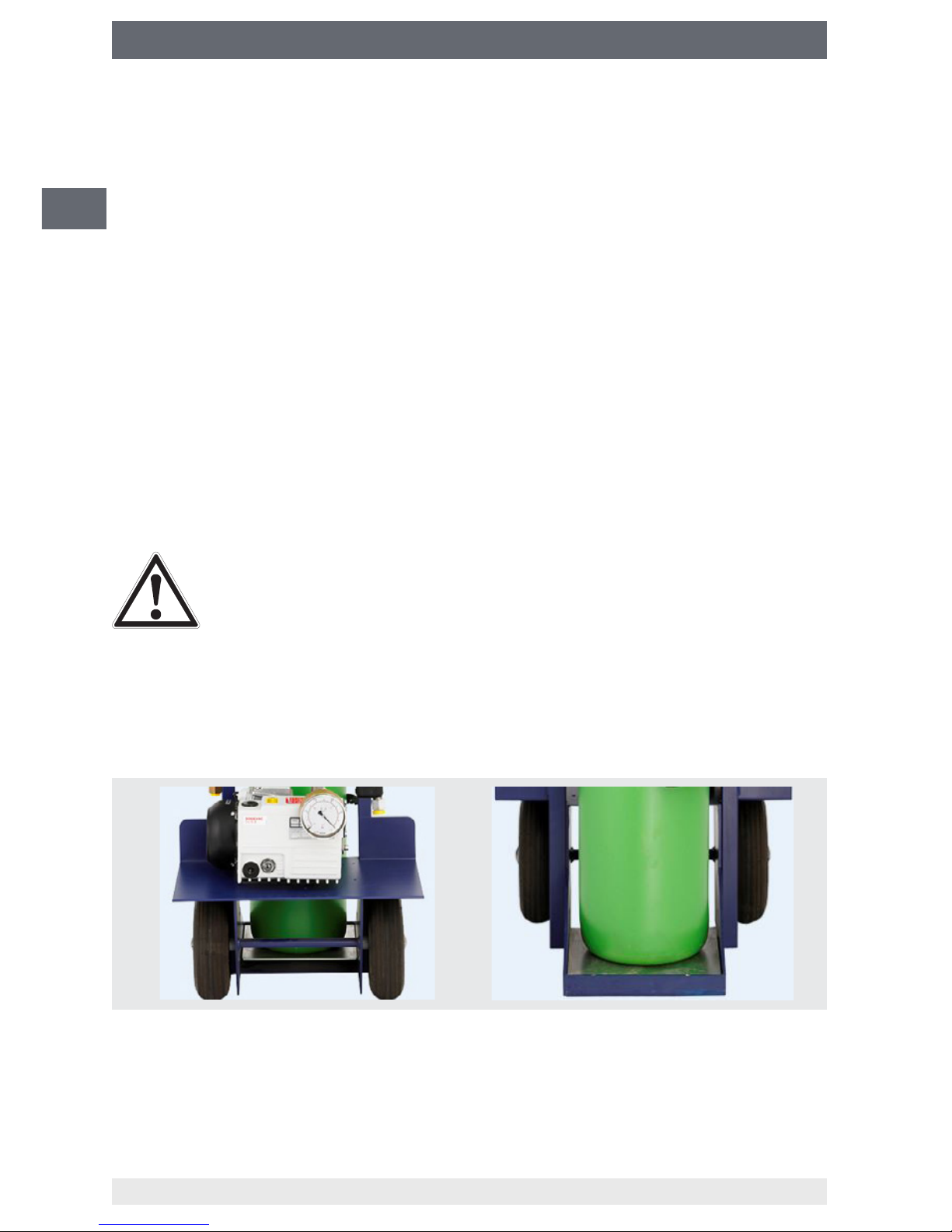
CAUTION!
Place the gas cylinder without the shunt forces of the fastening elements
(ratchet strap or chain) on the scale plate.
Secure the gas cylinder against falling over!
Place the SF
6
gas lling cart level on solid ground in order to make a precise weight
measurement.
Correct position of the gas cylinder on the scale plate:
Page 23

23
WIKA operating instructions SF6 gas lling cart, model GFU08
14033074.01 11/2018 EN/DE/FR/ES
EN
MODE
TARE
Press the TARE button on the digital display. The display shows 0.000 kg or 0.00 lbs,
depending on the set unit or number of decimal places.
6. Commissioning, operation
6.5.4 SF6 gas flows into the gas compartment
CAUTION!
Wear suitable gloves to protect your hands against frostbite.
■
Slowly open the outlet valve on the pressure reducer so that the SF6 gas can ow into
the gas compartment provided for this. Based on the gas properties, it is possible
that the gas, due to the quick expansion, gets very cold if the cylinder is opened very
quickly.
■
Fill the gas compartment according to the lling parameters indicated by the
manufacturer. Use suitable measuring devices.
■
Remove the lling hose from the gas compartment after having reached the lling
parameters.
6.5.5 Reading the filled gas quantity (models GFU08-W and GFU08-C with scales)
After the lling process, the quantity lled into the gas compartment is displayed with
negative sign on the digital display of the scales.
The MODE button can be used to switch between the complete weight and the TARE
weight (GROSS/NET).
Further information on the digital display of the scales: → See chapter 7 “Display unit”.
Page 24

24
WIKA operating instructions SF6 gas lling cart, model GFU08
14033074.01 11/2018 EN/DE/FR/ES
EN
7. Display unit
7.1 Display
7. Display unit
Lights up with external voltage supply
MODE button
Digital display
TARE button
C button
ZERO button
ENTER/PRINT button
Control light
Button Function
C/i
■
Switches the display unit on/off.
■
With numeric input, the current value is set to zero.
■
In SETUP: Leaves the step without confirming any change.
■
Displays the metric information: Capacity, graduations, minimum
weight for each configured range.
ENTER/PRINT
■
Enables the execution of a specific function, dependent on the
functionality selected in SETUP.
■
Numeric input: Confirmation of the input or change
■
In SETUP: Confirmation of the input, opening a parameter for
changing.
MODE
■
Enables the operating mode previously selected in SETUP.
■
With numeric input, one selects the value to be altered, from left to
right.
Page 25
25
WIKA operating instructions SF6 gas lling cart, model GFU08
14033074.01 11/2018 EN/DE/FR/ES
EN
Button Function
TARE
■
With a short press, the semi-automatic tare function will be executed.
■
After a longer press, a manual input can be made.
■
Annuls the negative tare value.
■
With numeric input, the figure will be increased.
ZERO
■
Annuls the negative tare value.
■
With a numeric entry, this reduces the number to be changed.
Settings in SETUP can only be carried out by WIKA personnel.
7.1.1 Numeric input
Via the five buttons of the display unit, a numeric value can be entered as follows:
Button Function
C/i
■
Short press: Displayed value will be set to zero.
■
Longer press: Return to weighing mode - without saving the
changes.
ENTER/PRINT
■
Confirms the entered value.
■
Quit input phase.
MODE
■
Select the figure to be changed (blinking).
■
Cursor moves from left to right.
TARE
■
Increases the selected figure.
ZERO
■
Reduces the selected figure.
7.1.2 Display
The letters and numbers on the display are represented as follows:
A B C D E F G H I J K L M
A B C D E F g h I J K L N
N O P Q R S T U V W X Y Z
n o P Q R S T u V W H Y 2
0 1 2 3 4 5 6 7 8 9
0 1 2 3 4 5 6 7 8 9
7. Display unit
Page 26

26
WIKA operating instructions SF6 gas lling cart, model GFU08
14033074.01 11/2018 EN/DE/FR/ES
EN
7.1.3 Automatic zero setting on start
If, during the start, a weight of ± 10 % of the nominal load/weighing capacity is
determined, an automatic zero setting is carried out. If the weight lies outside of this
range, the display on the display unit shows the current weight after a few moments.
7.1.4 Keylock
In order to prevent unwanted entries, the buttons of the display unit can be locked. The
settings for the keylock are made in SETUP.
Automatic keylock
The keypad will be locked after 15 seconds of inactivity in the weighing status (the
display indicates “LoC.key”).
Functions with keylock:
■
Switch the display unit off by pressing the C button for 10 seconds. Switches the
display unit back on.
■
Unlocking the keypad: Press the ZERO and ENTER/PRINT buttons one after the
other. (Display shows the message “unl.key”). By pressing any other button, the
display shows the message “Press Zero to unlock”. By pressing the ZERO
button, the display shows the message “now Press Print to unlock”.
Keylock via optional input
The keypad will be locked on closing the input and only unlocked again after opening it.
The display shows no message on locking/unlocking. If a button is pressed, the display
shows the message “LoCkin”.
7.2 Switching the display unit on
To switch the display unit on, press the C button until the display unit switches on.
Release the button.
Indication on the display after switching on:
Step Display Description
1
HH.YY
Indicates the installed software version.
2 Indicates all segments and symbols in the display.
3
NAH HHH.HHH
Weighing capacity of channel 1.
or
Naster
by selecting the function range “Nastr”.
or
ripE
by selecting the function range “rEpE”.
4
bt HHH
Indicates the charge status of the battery - “H” corresponds to
a number from 0 to 100.
5 Display of weighing capacity and scale divisions.
7. Display unit
Page 27

27
WIKA operating instructions SF6 gas lling cart, model GFU08
14033074.01 11/2018 EN/DE/FR/ES
EN
Step Display Description
6
hirES
Non-calibratable display unit.
or
LEGAL
Calibratable display unit.
7 Display unit performs countdown for self-checking.
7.2.1 Switching off
Keep the C button pressed until the message “-off-” is shown in the display.
In order to the switch the display unit off and then on again, keep the C button pressed
for 8 seconds. The display unit switches off and then automatically switches back on.
7.3 Zeroing the scales
If the gross weight lies within ± 2 % of the nominal load, it is possible to set the display
unit to zero by pressing the ZERO button. The display no longer indicates any weight
and the power-on lamp lights up, and symbols are shown on the display.
7.4 Function of the MODE button
Operating
modes
Button
Effect Button Effect Button
STANDARD MODE Change units
between kg and lb
NET/GROSS MODE Switching between
gross and net
weight
SETPOINT ENTER With model GFU-08
SF
6
gas lling cart,
without function
IN/OUT MODE Input weight ENTER Output weight
ALIBI MEMORY MODE Input of recall
number
ENTER Input of ID number ENTER
TOLERANCE
CHECK
MODE Input of target
weight
ENTER Input of minus
tolerance weight
>>>>>
ENTER Input of plus
tolerance weight
ENTER Input of minimum
weight
ENTER
PERCENT MODE Input of % value ENTER MODE button:
a) Changes % to
weight
MODE button 2 sec.:
b) Piece
7. Display unit
Page 28

28
WIKA operating instructions SF6 gas lling cart, model GFU08
14033074.01 11/2018 EN/DE/FR/ES
EN
Operating
modes
Button
Effect Button Effect Button
DISPLAY x 10 MODE Activates/deactiva-
tes the 10 x higher
resolution
HOLD MODE Activates/deactiva-
tes the weight/hold
function
PEAK MODE Activates/deactiva-
tes the peak value
display
TOTALISER MODE Total
Individual weighing
ENTER Total
ENTER 2 seconds: Overall
total
NUMBER OF
ITEMS
MODE Enters the number
of parts
ENTER MODE button:
a) Changes pieces to
weight
MODE button 2 sec.:
b) Piece
7.5 Tare function
With the tare function, before filling, the weight of the gas cylinder can be tared. With
this, the exact filling weight can be read off the display unit.
7.5.1 Semi-automatic taring
By pressing the TARE button, the weight resting on the scales is tared. The display
indicates “tArE” for a moment and then “0” (net weight). Semi-automatic taring only
occurs when the weight is at least one digit, is stable, and has a valid value, i.e. no
overload condition is allowed.
7.5.2 Taring via the keypad
1. Press the TARE button for a few seconds.
⇒
On the display is indicated: “- tn -”, then “000000”.
2
.
Enter the required value via the buttons.
→ see chapter 6.1.1 “Numerical input”.
3
.
Confirm with ENTER/PRINT button.
⇒
The value will be subtracted from the applied weight. The control light lights up.
7. Display unit
Page 29

29
WIKA operating instructions SF6 gas lling cart, model GFU08
14033074.01 11/2018 EN/DE/FR/ES
EN
7.5.3 Deleting the tare
The tare value can be cleared in the following ways:
■
Remove the load from the scales and press the TARE button (only with net weight at
zero and not negative)
■
Unload the scales and press the ZERO button
■
When using the tare function several times, one after the other, load the scales in
stages (each time press the TARE button once)
■
Press button C without unloading the scales
■
Enter “0” as the manual tare value
■
Tare value is deleted automatically (→ see chapter 6.5.4 “Tare locked/unlocked/
deactivated”)
7.5.4 Tare locked / unlocked / deactivated
Press the MODE button twice, one after the other, in order to set the tare type:
Display Description
loCK
Tar e locked:
If the tare value has been entered, on unloading the scales, the display shows
the value of the tare with a minus sign.With manual input of the tare value, or
adopting the value from memory, the net weight before the unloading of the
scales must be stable to at least two digits.
unloCk
Tar e unlocked:
The tare value will be deleted for each loading of the scales.
Auto
Automatic tare:
If a weight is placed on the empty scales, it is tared automatically only if there is
no existing tare and a stable gross weight of at least 5 g is present.
disAblE
Tar e deactivated:
All tare processes are deactivated.
The display stores the last values selected.
7.5.5 Limitations of the tare functions
For scales with a nominal load of 100 kg, all tare functions are switched off.
For scales with a nominal load/weighing capacity over 100 kg:
■
The value of the semi-automatic taring cannot, with a manual tare or from the
memory, be changed, i.e. the manual tare or from the memory can only be entered
for unladen scales and when the tare is 0.
■
The value of the taring can only be deleted with unladen scales if the ZERO button is
pressed or a manual taring of 0 is entered.
7. Display unit
Page 30

30
WIKA operating instructions SF6 gas lling cart, model GFU08
14033074.01 11/2018 EN/DE/FR/ES
EN
7.6 Automatic power-off
The “Automatic power-off” function is activated/deactivated via SETUP.
If the weighing platform is unladen, if the load is not moved or if, in the set time period
(1 to 255 minutes), no button is pressed, the display will show a blinking “-oFF-”. After
an audible signal, the display unit will automatically switch off.
7.7 Automatic stand-by function
The “Auto stand-by” function is activated/deactivated via SETUP.
The display unit is generally in stand-by mode (the display is switched off, except for the
decimal point). On pressing any button, the message “- on -” will be shown briefly. The
weight on the scales will be displayed for 30 seconds. After this time, the display unit will
return to the stand-by mode.
7.8 Setting the date/time
The display unit can be fitted with the date/time option or it could already be fitted. As
soon as the display unit is (for the first time) switched on, the display shows “CloCK”.The
setting of date and time is made in the SETUP area.
7.9 Print
If a printer is connected, there is the possibility to print the programmed weight data,
such as:
■
4 headers, each of 24 characters
■
Gross weight
■
Net weight
■
Number of print document
■
Hour and date (optional or as standard, depending on model)
■
Barcode from model 39
It is also possible to send the weight data to a PC via the printer port. This is achieved
via standard or extended string (parameter “ALL.Std/ALL.EHt o PrPC.St/PrPC.EH in
Pr.NodE”).
■
The print is confirmed by the display of the “PRinT” message in the display, or the
message “-tot-” in the case of totalising.
■
If the printing is no longer activated, the display shows the message “no.0.un.5”.
■
For unstable weights, the display shows the message “unStAb”.
■
If the gross or net weight is smaller than the required minimum load, after pressing
the ENTER/PRINT button, the display shows the error message “LoW”.
■
If the display unit has an under or overload, after pressing the ENTER/PRINT button,
the display shows the error message “un.oVEr”
.
7. Display unit
Page 31

31
WIKA operating instructions SF6 gas lling cart, model GFU08
14033074.01 11/2018 EN/DE/FR/ES
EN
7.9.1 Restoring the printing and display functions
During the use of the display unit, it is possible that the error “no.0.un5” is shown on
the display and a signal tone sounds. This means that the printing or the function to be
carried out must be re-enabled (in order to prevent unwanted applications).This function
is very useful in order to, for example, prevent a duplicate data output on the printer
or PC, or even a double summation.It is possible to define this restoration in different
ways in the SETUP area: “Returning the net weight over 0”, “Instability of the weight” or
“always”.
7.9.2 Display of the metric data
The display unit is fitted with the function “inFO”. Through this it is possible to display the
metric data of the scales:
▶
hold the C button down until the word “inFO” is shown on the display or
▶
press the MODE + C buttons
7.10 Selecting the operating mode
In addition to the standard weighing mode, tare deduction and the output of data, the
display unit can be switched to the following operating modes:
■
Changing over weight unit
■
Switching between gross/net
■
Input/output (“inout”)
7.10.1 Changing over the weight unit
By pressing the MODE button, it switches between kg and lb and vice versa.
▶
The calculation is carried out for the weight unit that is set during the
calibration.
▶
After changing the weight units over, the display unit must be
recalibrated.
7.10.2 Switching between GROSS/NET
If a tare has been entered, by pressing the MODE button, the gross weight is shown
on the display for 3 seconds.During the display of the gross weight, no printing can be
made.
7. Display unit
Page 32

32
WIKA operating instructions SF6 gas lling cart, model GFU08
14033074.01 11/2018 EN/DE/FR/ES
EN
7.10.3 Input/output (“inout”)
Simple weighing function in input/output mode: The operator selects two weight values
which the display acquires as input weight and as output weight. The electronics
calculate the difference between these two values and automatically prints out the data
(when a printer is connected).
In this operating mode, all tare procedures are deactivated
Performing the weighing function
1. Press the MODE button for the first weighing
⇒
Shown on the display: “--I---” accompanied by a long tone
2
.
Carry out the weighing.
3
.
Press the MODE button again for the second weighing.
⇒
Shown on the display: “--2---” accompanied by a long tone
4 Carry out the weighing.
5
⇒
Data is printed.
Annulling the weighing process
How to interrupt the weighing cycle:
1. Press the ENTER/PRINT button after completing the first weighing.
⇒
Shown on the display: “CLEARP” accompanied by a long tone
2
.
Press the ENTER/PRINT button in order to confirm the deletion of the first weighing.
OR
press any other button to continue with the second weighing - without deletion.
7. Display unit
Page 33

33
WIKA operating instructions SF6 gas lling cart, model GFU08
14033074.01 11/2018 EN/DE/FR/ES
EN
8. Instrument messages during operation
Display Description
2ERO
The scales are trying to effect a zero setting
AL.Err
The alibi memory is selected, but on starting the scales, no alibi memory is connected or the data communication between the display and the keypad is faulty.
Er I.b.H
A function is linked to input X (from 1 to 4) and is not “present”. See SETUP area
under “input5”.
Er.r.b.H
In a switch point function, the relay X (from 1 to 4) has been set and is not “present”.
See SETUP area under “output”.
busy
Printing is in progress (serial connection PRN is busy) or the display unit is waiting to
be able to send a print to the PC.
unstAb
Printing attempt with an unstable weight.
un.oUEr
Printing attempt in over or underload condition, i.e. with a weight that is 9 scale divisions greater than the nominal load or 100 scale divisions under the gross zero.
LoW
The net weight is less than the minimum load required for printing or totalling, or less
than the minimum weight for transferring a data string by pushbutton.
no.0..un5
Weight has not passed net 0 or was not unstable (depending on configuration).
ConU.
On legally calibrated instruments, an attempt was made to print in the standard
setting while the instrument was adjusting the weight unit.
no in
In the input/output function (activated as “in .out”), a second attempt was made to
acquire the input weight.
no out
In the input/output function (activated as “in .out”), a second attempt was made to
acquire the output weight.
no 1
In the input/output function (activated as “G.t.” or “1St.2nd”), a second attempt was
made to acquire the input weight.
no 2
In the input/output function (activated as “G.t.” or “1St.2nd”), a second attempt was
made to acquire the output weight.
Er.Not
Unstable weight.
Error
In counting mode, the reference determination was not or not properly performed, or
a larger reference quantity is required. During the comparison procedure, the load
cell with which the comparison is performed does not correspond to the rated load or
values have not been entered or have been entered in the wrong order.
E9..Err
Is displayed when the execution of the comparison was not possible.
StorE
Is displayed when data has been stored in the permanent memory of the instrument
(switch points, tare, updated record, etc.)
Err.Clk
Problem with the date/time cards. Setting of “F.NodE” >> “Clock” in SETUP.
SEt.Clk
Date/Time not set. Setting of “F.NodE” >> “Clock” in SETUP.
PrEC.
Is displayed when attempting to perform the zero calibration without first confirming
the number of calibration points.
8. Instrument messages during operation
Page 34

34
WIKA operating instructions SF6 gas lling cart, model GFU08
14033074.01 11/2018 EN/DE/FR/ES
EN
Display Description
Er.Pnt
During the acquisition of a calibration point, an invalid value is read from the transducer.
Err.rF
Is displayed if, during the selection of the function “NAStEr” and the activation of
the power-saving mode of the indicator, a SLAVE instrument is not found after 60
seconds. This message is displayed if the radio module is activated.This message is
displayed for 3 seconds and then the display is switched off.
Er 11
Calibration error: Too low a comparison weight has been used; it is recommended to
use a weight that corresponds to at least half the nominal load of the scales.
Er 12
Calibration error: The acquired calibration point (“tP1” or “tP2” or “tP3”) is the same as
the zero point (“tP0”).
Er 37
The number of points of the transducer for the subdivision of the scales is less than
two. Carry out the calibration again (correctly), paying attention to the nominal load
and the scale divisions.
Er 39
Occurs when the instrument is not yet initialised and calibrated.
When the instrument displays “ER 39”, press the TARE button, in order to access
the SETUP area. Carry out the initialisation of the display unit (Parameter “dEFAu”),
the selection of the keypad type (parameter “keyb”), the programming of all parame-
ters of the SETUP area and the calibration of the instrument.
ER 85
Occurs when the instrument has been initialised, but not yet calibrated.
When the instrument displays “ER 85”, press the TARE button, in order to access
the SETUP area.
C.Er.36
During calibration, internal, negative points have been calculated:
■
The calibration point lies below the zero point.
■
The signal is negative (check the cable connections to the load cell).
undEr
(blinking)
The scale is in underload (i.e. the weight on the scale is ≤ 100 scale divisions under
the gross zero, when the instrument is legally calibrated). This message is accompanied by an acoustic signal.
oVEr
(blinking)
The scales are in overload (i.e. the weight on the scales is 9 scale divisions greater
than the nominal load/weighing capacity). This message is accompanied by an
acoustic signal.
Eco H
Is shown for a moment when the master instrument manages to connect to the slave
instrument X. When the connection is not possible, the message persists and the
master instrument emits an acoustic signal.
tilt
The connected tilt sensor is preventing a weighing process.
The message is displayed when the tilt of a pallet truck is greater than 2 % or, with a
fork-lift truck, is greater than 5 %.The activation of the “TILT alarm” is carried out with
approx. 3 seconds delay.
8. Instrument messages during operation
Page 35

35
WIKA operating instructions SF6 gas lling cart, model GFU08
14033074.01 11/2018 EN/DE/FR/ES
EN
9. Maintenance and cleaning
9.1 Maintenance
The SF
6
gas lling cart is maintenance-free. Information on the maintenance of the
optional vacuum pump components see chapter “Vacuum pump”.
Vacuum pump (models GFU08-E and GFU08-C)
The most important maintenance factor for a vacuum pump is the oil. This must be
replaced when it is strongly contaminated (dark or cloudy oil). After the evacuation of
contaminated refrigerant, the oil must also be replaced. In particular, moisture/water
which remains in the pump until the next use can lead to damage of the pump through
corrosion.
Contaminated oil can damage the vacuum pump.
Process for oil change:
1. Let the pump run warm to the working temperature, then switch o and pull out the
mains plug.
2
.
Unscrew the oil mist separator.
3
.
Drain the oil by opening the outlet plug, or pour it out through the hole of the oil mist
separator by tilting the pump.
4. Plug in the mains plug - switch the pump on. Let it run for approx. 5-10 seconds with
the suction pipe open, so the residual oil is forced out of the pressure stages.
5. Switch the pump o - pull out the mains plug.
6. Drain or pour out the residual oil.
7. Screw the oil drain plug back in tightly.
8. Fill the new oil back to the ll level “middle sight glass”.
9. Screw in the oil mist separator. Briey switch on the pump for a few seconds.
With heavily contaminated oil, it is recommended to repeat the oil change
after about 30 minutes running in order to rinse out all of the contamination.
In order to achieve the specied performance and to not damage the pump, only ever
use WIKA oil.
The used oil must be disposed of properly by the pump operator in
accordance with regulations!
Repairs must only be carried out by the manufacturer.
9. Maintenance and cleaning
Page 36

36
WIKA operating instructions SF6 gas lling cart, model GFU08
14033074.01 11/2018 EN/DE/FR/ES
EN
9.2 Cleaning
CAUTION!
■
Clean the instrument with a moist cloth.
■
Do not use aggressive cleaning agents
■
Do not use any pointed or hard objects for cleaning.
10. Faults
In the event of leaks on lines lled with SF6 gas, the system must be stopped immediately
by closing the gas cylinder valve and the leaks must be eliminated by skilled personnel.
The SF
6
gas lling cart can, following successful leak testing, e.g. with a WIKA model
GIR-10, be put back into service.
Faults in the display unit
Faults Causes Measures
Display unit without function. Display unit not switched on. Switch on the display unit.
Battery empty. Charge the battery.
Display unit indicates no
value, even though there is a
weight on the scales.
Defective connection cable/
cable break.
Check the connection of the
display unit with the scales.
If complaint is unjustified, we will charge you the complaint processing fees.
Faults in the vacuum pump
Faults Causes Measures
Pump is dicult to start. The
speed is too low.
Oil too cold. Place the pump in a warm
environment.
Third-party oil is too viscous. Replace with original oil.
Pump is dirty. Carry out the oil change.
Motor windings defective. Ask customer service.
The connection cable is too
long.
Use a shorter connection
cable.
Mains voltage is too low. Pump is designed for mains
voltage ± 10 %.
Motor will not start. Capacitor defective. Replace capacitor.
Switch defective. Replace switch.
Motor too hot. Allow it to cool.
Cable defective. Replace cable.
9. Maintenance and cleaning / 10. Faults
Page 37

37
WIKA operating instructions SF6 gas lling cart, model GFU08
14033074.01 11/2018 EN/DE/FR/ES
EN
Faults Causes Measures
Engine hums - pump
blocked.
Pump contaminated. Pump
silted up.
Replace the pressure stage.
Ask customer service.
Motor is running ⇒ No power Coupling pin broken. Ask customer service.
Oil splashes on the oil mist
separator.
Oil reservoir is overlled. Oil level to “middle sight
glass”. Drain o excess oil.
Oil mist formation Operating pressure = atmos-
pheric pressure
Oil mist reduces after the
build up of suction pressure.
Oil level not visible. Oil volume too low. Rell with oil.
Oil contaminated/cloudy. Dirty refrigerant/oil sucked in. Carry out the oil change.
Pump does not achieve
vacuum.
Open the gas ballast valve. Turn the gas ballast valve to
closed.
Loosen the cap on the intake
port.
Screw the cap tight.
O-ring in the cap of the intake
port is defective.
Replace the O-ring.
Oil level too low. Rell with oil.
Oil silted up or contaminated. Change oil.
Line leaking. Check line, seal it.
Pump is worn after long
usage.
Repair or replace the pump.
Pump generates noise Motor bearings defective. Ask customer service.
Ventilator defective. Replace the ventilator.
Pump is losing oil. Oil housing sealing defect. Replace the O-ring.
Oil drain plug leaking. Replace drain plug.
Sight glass sealing defective. Replace the sight glass.
Oil housing tting leaking. Replace the seals of the oil
housing tting.
Shaft seal defective. Ask customer service.
10. Faults
Page 38

38
WIKA operating instructions SF6 gas lling cart, model GFU08
14033074.01 11/2018 EN/DE/FR/ES
EN
11. Dismounting and disposal
WARNING!
Residual media in the dismounted SF
6
gas lling cart can result in a risk
to persons, the environment and equipment.
Take sucient precautionary measures.
11.1 Dismounting
Only disconnect the SF
6
gas lling cart once the system has been depressurised!
11.2 Disposal
Incorrect disposal can put the environment at risk.
Dispose of instrument components and packaging materials in an environmentally
compatible way and in accordance with the country-specic waste disposal regulations.
11. Dismounting and disposal
Page 39

39
WIKA Betriebsanleitung SF6-Gas Füllwagen, Typ GFU08
DE
14033074.01 11/2018 EN/DE/FR/ES
Inhalt
1. Allgemeines 40
2. Sicherheit 41
3. Technische Daten 52
4. Aufbau und Funktion 54
5. Transport, Verpackung und Lagerung 55
6. Inbetriebnahme, Betrieb 56
7. Anzeigeeinheit 60
8. Gerätemeldungen während der Nutzung 69
9. Wartung und Reinigung 71
10. Störungen 72
11. Demontage und Entsorgung 74
Inhalt
Page 40

40
WIKA Betriebsanleitung SF6-Gas Füllwagen, Typ GFU08
DE
14033074.01 11/2018 EN/DE/FR/ES
1. Allgemeines
1. Allgemeines
■
Der in der Betriebsanleitung beschriebene SF6-Gas-Füllwagen wird nach den
neuesten Erkenntnissen konstruiert und gefertigt. Alle Komponenten unterliegen
während der Fertigung strengen Qualitäts- und Umweltkriterien. Unsere
Managementsysteme sind nach ISO 9001 und ISO 14001 zertiziert.
■
Diese Betriebsanleitung gibt wichtige Hinweise zum Umgang mit dem Gerät.
Voraussetzung für sicheres Arbeiten ist die Einhaltung aller angegebenen
Sicherheitshinweise und Handlungsanweisungen.
■
Die für den Einsatzbereich des Gerätes geltenden örtlichen
Unfallverhütungsvorschriften und allgemeinen Sicherheitsbestimmungen einhalten.
■
Die Betriebsanleitung ist Produktbestandteil und muss in unmittelbarer Nähe des
Gerätes für das Fachpersonal jederzeit zugänglich aufbewahrt werden.
■
Das Fachpersonal muss die Betriebsanleitung vor Beginn aller Arbeiten sorgfältig
durchgelesen und verstanden haben.
■
Die Haftung des Herstellers erlischt bei Schäden durch bestimmungswidrige
Verwendung, Nichtbeachten dieser Betriebsanleitung, Einsatz ungenügend
qualizierten Fachpersonals sowie eigenmächtiger Veränderung am Gerät.
■
Es gelten die allgemeinen Geschäftsbedingungen in den Verkaufsunterlagen.
■
Technische Änderungen vorbehalten.
■
Weitere Informationen:
- Internet-Adresse: www.wika.de/sf6, www.wika.com/sf6
- zugehöriges Datenblatt: SP 63.08
- Anwendungsberater:
Tel.: (+49) 9372/132-8971
E-Mail: sf6-sales@wika.de
Page 41

41
WIKA Betriebsanleitung SF6-Gas Füllwagen, Typ GFU08
DE
14033074.01 11/2018 EN/DE/FR/ES
2. Sicherheit
2. Sicherheit
2.1 Bedeutung dieser Betriebsanleitung
■
Diese Betriebsanleitung gibt wichtige Hinweise zum Umgang mit dem SF6-GasFüllwagen. Voraussetzung für sicheres Arbeiten ist die Einhaltung aller angegebenen
Sicherheitshinweise und Handlungsanweisungen. Zuwiderhandlungen können zu
gefährlichen Situationen führen.
■
Betriebsanleitung an nachfolgende Benutzer oder Besitzer des SF6-Gas-Füllwagens
weitergeben.
■
Vor allen Arbeiten muss der Betreiber sicherstellen, dass das Personal die Betriebsanleitung und Sicherheitsdatenblätter sorgfältig durchgelesen hat.
■
Die aufgabenbezogen Sicherheitshinweise sind am Anfang der jeweiligen Kapitel zu
nden (z. B. Transport, Inbetriebnahme, ...)
2.2 Symbolerklärung
GEFAHR!
... weist auf eine unmittelbar gefährliche Situation hin, die zum Tod oder
zu schweren Verletzungen führt, wenn sie nicht gemieden wird.
GEFAHR!
... kennzeichnet Gefährdungen durch elektrischen Strom. Bei Nichtbeachtung der Sicherheitshinweise besteht die Gefahr schwerer oder tödlicher
Verletzungen.
WARNUNG!
... weist auf eine möglicherweise gefährliche Situation hin, die zum Tod
oder zu schweren Verletzungen führen kann, wenn sie nicht gemieden
wird.
VORSICHT!
... weist auf eine möglicherweise gefährliche Situation hin, die zu geringfügigen oder leichten Verletzungen bzw. Sach- und Umweltschäden
führen kann, wenn sie nicht gemieden wird.
Information
... hebt nützliche Tipps und Empfehlungen sowie Informationen für einen
ezienten und störungsfreien Betrieb hervor.
Page 42

42
WIKA Betriebsanleitung SF6-Gas Füllwagen, Typ GFU08
DE
14033074.01 11/2018 EN/DE/FR/ES
2. Sicherheit
Handlungsanweisungen
2. 3. Handlungssequenz
Handlungsanweisungen sind in vorgegebener Reihenfolge durchzuführen.
▶
Handlungsanweisung
Handlungsanweisungen ohne vorgegebene Reihenfolge.
⇒
Resultat
Beschreibt das Resultat einer Handlung.
→ Querverweis
Verweist auf eine weitere Stelle in der Betriebsanleitung.
2.3 Bestimmungsgemäße Verwendung
Das Gerät ist ausschließlich für den hier beschriebenen bestimmungsgemäßen Verwendungszweck konzipiert und konstruiert und darf nur dementsprechend verwendet
werden. Ansprüche jeglicher Art aufgrund von nicht bestimmungsgemäßer Verwendung
sind ausgeschlossen.
Verwendungszweck
Der SF
6
-Gas-Füllwagen dient der Füllung bzw. Nachfüllung von SF6-Gas in dafür vorgesehene und zugelassene gasdichte Behälter. Dabei kann der Fülldruck am eingebauten
Druckminderer eingestellt werden.
Der SF
6
-Gas-Füllwagen Typ GFU08-W bzw. GFU08-C enthält zusätzlich eine Waage
zur Messung der transferierten Masse SF
6
-Gas.
Der Typ GFU08-E bzw. GFU08-C enthält zusätzlich eine Vakuumpumpe, mit der der
Gasraum vor der Füllung evakuiert werden kann.
Es ist darauf zu achten, dass die Vakuumpumpe nur zum Abpumpen von Luft und nicht
von SF
6
-Gas verwendet wird.
Einsatzbereiche
Den SF₆-Gas Füllwagen nur in Anwendungen verwenden, die innerhalb seiner technischen Leistungsgrenzen liegen (z. B. max. Umgebungstemperatur, Materialverträglichkeit, ...).
→ Leistungsgrenzen siehe Kapitel 3 „Technische Daten“.
Der SF₆-Gas Füllwagen eignet sich für den Innen- und Außeneinsatz. Für einen siche-
ren Betrieb muss der Aufstellort folgende Vorraussetzungen erfüllen:
■
Aufstellort ist jederzeit durch Fachpersonal beaufsichtigt oder nicht allgemein
zugänglich.
■
Der Untergrund ist stets waagerecht und eben.
■
Nicht-explosionsfähige Atmosphäre.
■
Nicht-korrosionsverursachende Atmosphäre.
■
Keine stark staubhaltige Atmosphäre.
■
Kein Betrieb im Außenbereich bei Regen oder Gewitter (IP20).
Page 43

43
WIKA Betriebsanleitung SF6-Gas Füllwagen, Typ GFU08
DE
14033074.01 11/2018 EN/DE/FR/ES
2. Sicherheit
■
Der Aufstellort muss genügend Platz aufweisen, damit ein sicherer Betrieb möglich
ist. Das Bedien- und Wartungspersonal muss sich frei um das Gerät bewegen
können.
■
Max. zulässige Umgebungstemperatur wird nicht überschritten.
SF
6
-Gas-Füllwagen mit Waage (Typ GFU08-W bzw. GFU08-C):
■
Elektronische Komponenten mit erforderlicher Sorgfalt behandeln (vor Nässe,
Stößen, starken Magnetfeldern, statischer Elektrizität und extremen Temperaturen
schützen, keine Gegenstände in das Gerät bzw. Önungen einführen). Stecker und
Buchsen vor Verschmutzung schützen.
■
Wird das Gerät von einer kalten in eine warme Umgebung transportiert, so kann
durch Kondensatbildung eine Störung der Gerätefunktion eintreten. Vor einer erneuten Inbetriebnahme die Angleichung der Gerätetemperatur an die Raumtemperatur
abwarten.
Die technischen Spezifikationen in dieser Betriebsanleitung sind einzuhalten. Eine
unsachgemäße Handhabung oder ein Betreiben des Gerätes außerhalb der technischen Spezifikationen macht die sofortige Stilllegung und Überprüfung durch einen
autorisierten WIKA-Servicemitarbeiter erforderlich.
Eigenmächtige Umbauten durch den Betreiber sind nicht gestattet, insbesondere an
Sicherheitseinrichtungen. Eigenmächtige Umbauten können dazu führen, dass Sicherheitseinrichtungen nicht ordnungsgemäß funktionieren und lebensgefährliche Situationen daraus resultieren.
WIKA haftet nicht für Änderungen, welche von Personen vorgenommen werden, die
nicht durch WIKA autorisiert sind.
Ansprüche jeglicher Art aufgrund von nicht bestimmungsgemäßer Verwendung sind
ausgeschlossen.
Technische Einschränkungen
Die technischen Spezikationen in dieser Betriebsanleitung sind einzuhalten. Eine
unsachgemäße Handhabung oder ein Betreiben des Gerätes außerhalb der techni-
schen Spezikationen macht die sofortige Stilllegung und Überprüfung durch einen
autorisierten WIKA-Servicemitarbeiter erforderlich.
Technische Spezikationen:
→ Siehe Kapitel 3 „Technische Daten“.
2.4 Verantwortung des Betreibers
Das Gerät wird im gewerblichen Bereich eingesetzt. Der Betreiber unterliegt daher den
gesetzlichen Pflichten zur Arbeitssicherheit.
Die Sicherheitshinweise dieser Betriebsanleitung, sowie die für den Einsatzbereich des
Gerätes gültigen Sicherheits-, Unfallverhütungs- und Umweltschutzvorschriften einhalten.
Page 44

44
WIKA Betriebsanleitung SF6-Gas Füllwagen, Typ GFU08
DE
14033074.01 11/2018 EN/DE/FR/ES
2. Sicherheit
Der Betreiber ist verpflichtet, das Typenschild lesbar zu halten.
Für ein sicheres Arbeiten am Gerät muss der Betreiber sicherstellen,
■
dass eine entsprechende Erste-Hilfe-Ausrüstung vorhanden ist und bei Bedarf jederzeit Hilfe zur Stelle ist.
■
dass das Bedienpersonal regelmäßig in allen zutreffenden Fragen von Arbeitssicherheit, Erste Hilfe und Umweltschutz unterwiesen wird, sowie die Betriebsanleitung
und insbesondere die darin enthaltenen Sicherheitshinweise kennt.
■
dass das Gerät gemäß der bestimmungsgemäßen Verwendung für den Anwendungsfall geeignet ist.
■
dass die persönliche Schutzausrüstung verfügbar ist.
2.5 Personalqualifikation
Alle Arbeiten an und mit dem SF
6
-Gas-Füllwagen dürfen nur durch geschultes und
autorisiertes Personal erfolgen.Es sind die jeweils gültigen nationalen Vorschriften zu
beachten, speziell zu Gefahrengut und Qualifikation des Personals.
Für Schulungen den Anwendungsberater kontaktieren.
Tel.: +49 9372 132-0
Fax: +49 9372 132-406.
Transport
Es sind die jeweils gültigen nationalen Vorschriften zu beachten, speziell zu Gefahren-
gut und Qualikation des Personals.
Bedienung
Es sind die jeweils gültigen nationalen Vorschriften zu beachten, speziell zu Gefahren-
gut und Qualikation des Personals.
In Europa muss das Bedienpersonal nach folgenden Verordnungen qualiziert sein:
■
F-Gase-Verordnung (EU) 517/2014
■
Verordnung (EG) 305/2008
Wartung
Die in dieser Betriebsanleitung beschriebenen Wartungsarbeiten dürfen nur von Personen durchgeführt werden, welche durch den Betreiber autorisiert sind. Wartungsarbeiten, welche in den Betriebsanleitungen von Zulieferkomponenten beschrieben werden,
sind nach deren Vorgaben und Anweisungen durchzuführen.
Verwendung in Hochspannungsanlagen
Der Betreiber muss sicherstellen, dass die Handhabung von SF₆-Gas durch ein hierzu
qualifiziertes Unternehmen oder von gemäß IEC 61634 Abschnitt 4.3.1 bzw. IEC 60480
Abschnitt 10.3.1 geschulten Mitarbeitern durchgeführt wird.
In der Europäischen Union muss jede Tätigkeit in Zusammenhang mit fluorierten Treibhausgasen von zertifiziertem Fachpersonal durchgeführt werden. Die Zertifizierung
muss gemäß Verordnung (EG) Nr. 305/2008 erfolgt sein.
Page 45

45
WIKA Betriebsanleitung SF6-Gas Füllwagen, Typ GFU08
DE
14033074.01 11/2018 EN/DE/FR/ES
2. Sicherheit
2.6 Zusätzliche Sicherheitshinweise für die Verwendung in Schaltanlagen
Der Betreiber muss sicherstellen, dass die Handhabung von SF
6
-Gas durch ein hierzu
qualifiziertes Unternehmen oder von gemäß IEC 61634 Abschnitt 4.3.1 bzw. IEC 60480
Abschnitt 10.3.1 geschulten Mitarbeitern durchgeführt wird.
Geltende Normen für SF
6
-Gas
■
Installation, Errichtung, Inbetriebnahme:
IEC 61634 (Handhabung von SF
6
),
IEC 60376 (neues SF
6
, technisches SF6),
IEC 60480 (gebrauchtes SF
6
),
CIGRE-report 276, 2005 (Practical SF
6
handling instructions)
■
Leckagen während des Betriebs:
IEC 60376 (neues SF
6
, technisches SF6),
IEC 60480 (gebrauchtes SF
6
),
CIGRE 2002 („SF
6
in the Electric Industry“)
■
Reparaturarbeiten und Wartung:
IEC 61634 (Use and handling of SF
6
in high-voltage switchgear and controlgear),
CIGRE 1991 (Handhabung von SF₆),
CIGRE-report 276, 2005 (Practical SF
6
handling instructions),
CIGRE-report 163, 2000 (Guide for SF₆ gas mixtures)
SF
6
-Gas ist farb-, bzw. geruchlos, chemisch neutral, inert, nicht entamm-
bar und ca. 5-mal schwerer als Luft, nicht toxisch und nicht ozonschädi-
gend. Detaillierte Angaben nden sich in IEC 60376 und IEC 61634.
2.7 Persönliche Schutzausrüstung
Die persönliche Schutzausrüstung dient dazu, das Personal gegen Gefahren zu schützen, die dessen Sicherheit oder Gesundheit bei der Arbeit beeinträchtigen könnten.
Beim Ausführen der verschiedenen Arbeiten an und mit dem SF
6
-Gas-Füllwagen muss
das Personal persönliche Schutzausrüstung tragen.
Die hier angegebene persönliche Schutzausrüstung steht ausschließlich im direkten
Zusammenhang mit dem beschriebenen Produkt. Weitere Anforderungen, die sich aus
den Umgebungsbedingungen am Ort der Nutzung, anderer Produkte oder der Verknüpfung mit anderen Produkten ergeben, sind nicht berücksichtigt.
Die erforderliche persönliche Schutzausrüstung muss vom Betreiber zur Verfügung
gestellt werden. Der Betreiber wird durch diese Vorschläge in keinster Weise von seinen
arbeitsrechtlichen Pflichten zur Sicherheit und dem Schutz der Gesundheit der Arbeitnehmer entbunden.
Die Bemessung der persönlichen Schutzausrüstung muss unter Berücksichtigung aller
Betriebsparameter des Einsatzortes erfolgen.
Page 46

46
WIKA Betriebsanleitung SF6-Gas Füllwagen, Typ GFU08
DE
14033074.01 11/2018 EN/DE/FR/ES
2. Sicherheit
Für eine sichere Handhabung des SF6-Gas-Füllwagens wird folgende persönliche
Schutzausrüstung benötigt:
Sicherheitsschuhe
Die Sicherheitsschuhe müssen bei Arbeiten an Gasbehältern (z. B.
Gaszylinder, Tanks) über die gesamte Dauer hinweg getragen werden.
Die Sicherheitsschuhe schützen die Füße vor herunterfallenden Teilen
und Flüssigkeitsspritzern.
Schutzbrille
Die Schutzbrille muss bei Arbeiten an Schläuchen oder Gasbehältern
(z. B. Gaszylinder, Tanks) über die gesamte Dauer hinweg getragen
werden. Die Schutzbrille schützt die Augen vor umherfliegenden Teilen,
austretendem Gas und Flüssigkeitsspritzern.
Schutzhandschuhe
Aufgrund der Gaseigenschaften kann es passieren, das bei schnellem
Öffnen das Gas durch die rasche Expansion sehr kalt wird.
Zum Schutz vor Erfrierungen Schutzhandschuhe tragen.
Sollten bei einer Gefährdungsanalyse des Betreibers verunreinigte Gase festgestellt
werden, sind bei nachträglichen Wartungsarbeiten der Verunreinigung entsprechende
Schutzmaßnahmen einzuleiten.
Atemschutzmaske
Die Atemschutzmaske muss bei Wartungsarbeiten der Schutzstufe
entsprechen, die für das entsprechende Gas im Sicherheitsdatenblatt
angegeben ist.
Schutzanzug
Die spezifische Schutzbekleidung muss bei Wartungsarbeiten über die
gesamte Dauer hinweg getragen werden. Die Schutzkleidung schützt den
Körper vor verunreinigtem SF₆-Gas. Der Betreiber muss die spezifische
Schutzkleidung entsprechend auswählen.
Page 47

47
WIKA Betriebsanleitung SF6-Gas Füllwagen, Typ GFU08
DE
14033074.01 11/2018 EN/DE/FR/ES
2. Sicherheit
2.8 Allgemeine Sicherheitshinweise
Inhalt der allgemeinen Sicherheitshinweise
Dieses Kapitel befasst sich mit der allgemeinen Sicherheit im Umgang mit SF
6
-Gas und
dem SF
6
-Gas-Füllwagen.
Die aufgabenbezogen Sicherheitshinweise sind am Anfang der jeweiligen Kapitel zu
nden und zu beachten (z. B. Transport, Inbetriebnahme, ...).
Umgang mit SF₆-Gas
SF₆-Gas ist ein Treibhausgas, das im Kyoto-Protokoll gelistet ist. Das SF₆-Gas darf
nicht in die Atmosphäre gelangen, sondern muss in geeigneten Behältern gesammelt
werden.
Eigenschaften von SF₆-Gas
■
Farb- und geruchlos
■
Chemisch neutral
■
Inert
■
Nicht entflammbar
■
Fünfmal schwerer als Luft
■
Nicht toxisch
■
Nicht ozonschädigend
Detaillierte Angaben befinden sich in der IEC 60376 und IEC 61634.
Erstickungsgefahr durch SF₆-Gas
Hohe Konzentrationen von SF₆-Gas können zur Erstickung führen, da beim Einatmen
von SF₆-Gas die Atemluft aus den Lungen verdrängt wird. Da SF₆-Gas schwerer ist
als Luft, sammelt es sich insbesondere in Bodennähe oder tiefer gelegenen Räumen
unterhalb des Bezugsniveaus an (z. B. Kellerräume). Dies ist besonders gefährlich, da
SF₆-Gas farb- und geruchlos ist und somit vom Menschen nicht wahrgenommen wird.
Gefährdung duch Zersetzungsprodukte
SF₆-Gas in elektrischen Anlagen kann durch Lichtbogeneinwirkung Zersetzungsprodukte
enthalten:
■
Gasförmige Schwefelflouride
■
Schwefeloxyfluoride
■
Feste staubförmige Metallfluoride, -sulfide und -oxide
■
Fluorwasserstoff
■
Schwefeldioxid
Zersetzungsprodukte können gesundheitsschädlich sein.
■
Durch Einatmen, Verschlucken oder Hautberührung kann es zu einer Vergiftung
kommen.
■
Augen, Atmungsorgane oder die Haut können gereizt und verätzt werden.
■
Durch Einatmen größerer Mengen kann die Lunge geschädigt werden.
Page 48

48
WIKA Betriebsanleitung SF6-Gas Füllwagen, Typ GFU08
DE
14033074.01 11/2018 EN/DE/FR/ES
Folgende Sicherheitshinweise beachten, um Gefahren durch SF₆-Gas zu vermeiden:
■
Persönliche Schutzausrüstung tragen.
■
Das Sicherheitsdatenblatt des Gaslieferanten lesen.
■
Für gute Belüftung sorgen.
■
Dichtigkeit der Betriebsmittel mit Gasdetektor sicherstellen (z. B. Typ GIR-10).
Verwendung von Zubehör und Ersatzteilen
Es wird empfohlen, nur Originalzubehör und Originalersatzteile von WIKA zu verwenden. Die Verwendung von Zubehör- und Ersatzteilen Dritter können aufgrund von Qualitätsmängeln oder anderer Ursachen zu Schäden am Gerät oder Unfällen führen.
WIKA übernimmt keine Haftung für Schäden oder Unfälle, die durch eine Fehlfunktion oder Nichteignung von Zubehör- und Ersatzteilen entstehen, die nicht von WIKA
stammen (z. B. undichte Verbindungsteile). Es können keine Garantieansprüche geltend
gemacht werden, die aufgrund einer Fehlfunktion oder Nichteignung eines Zubehöroder Ersatzteiles Dritter entstehen.
Stolpergefahr durch unsachgemäße Verlegung von Verbindungen
Unsachgemäß verlegte Verbindungen wie Kabel, Schläuche oder Rohrleitungen stellen
Stolperquellen dar und können dadurch zu erhebliche Verletzungen führen.
Verbindungen immer so verlegen, dass keine Stolperquellen entstehen. Unumgängliche
Stolperstellen mit gelbschwarzem Markierband kennzeichnen.
2.9 Restgefahren
Was sind Restgefahren?
Das Gerät wurde so konstruiert, dass keine Person vermeidbaren Gefahren ausgesetzt
ist. Besondere Gefahrenstellen werden durch spezielle Schutzeinrichtungen gesichert.
In der Betriebsanleitung wird durch die Sicherheitshinweise auf diese Gefahrenstellen
und das erforderliche Verhalten des Personals hingewiesen, um aus den Gefahrenstellen resultierende Risiken zu minimieren.
2.10 Regelmäßige Sicherheitsüberprüfung
Der Betreiber ist verantwortlich, das Gerät mindestens einmal jährlich oder nach besonderen Vorkommnissen zu überprüfen. Die Überprüfung ist nur durch WIKA oder von
WIKA-Partnerfirmen autorisierte und ausgebildete Personen durchzuführen.
Dabei muss eine vollständige Prüfung des technischen Zustandes in Bezug auf Unfallsicherheit durchgeführt werden. Außerdem muss das Gerät samt aller Komponenten
gründlich auf Beschädigungen untersucht werden.
Für die umgehende Beseitigung von Mängeln muss der Betreiber sorgen.
2. Sicherheit
Page 49

49
WIKA Betriebsanleitung SF6-Gas Füllwagen, Typ GFU08
DE
14033074.01 11/2018 EN/DE/FR/ES
2. Sicherheit
2.11 Besondere Gefahren
GEFAHR!
Lebensgefahr durch elektrischen Strom
Bei Berührung mit spannungsführenden Teilen besteht unmittelbare
Lebensgefahr.
■
Einbau und Montage des Gerätes dürfen nur durch Fachpersonal
erfolgen.
■
Bei Betrieb mit einem defekten Netzgerät (z. B. Kurzschluss von
Netzspannung zur Ausgangsspannung) können am Gerät lebensgefährliche Spannungen auftreten!
WARNUNG!
■
Die medienberührten Teile wurden ausschließlich für SF6-Gas bzw.
mit Verwendung eines optional erhältlichen Adapters auch für N
2
konzipiert.
■
Die Leitungen bei montiertem Füllschlauch sind mit SF6-Gas vorgefüllt. Der Fülldruck der Transportfüllung beträgt ca. 200 mbar (2.9 psi)
SF
6
-Gas.
Typen GFU08-E, GFU08-C
WARNUNG!
■
Das Anklemmen elektrischer Anschlüsse ist nur durch Elektrofachpersonal zulässig
■
Nach korrekter Inbetriebnahme darf der SF6-Gas-Füllwagen nur in
aufrechter Position bewegt werden. Andernfalls kann Öl aus dem
Gehäuse auslaufen.
■
Zur Evakuierung mit der Vakuumpumpe nur den mitgelieferten
Schlauch verwenden
■
Den SF6-Gas-Füllwagen nicht im Regen bzw. in feuchter Umgebung
betreiben
■
Ölstand der Vakuumpumpe regelmäßig überprüfen und ggf. anpassen
■
Mit der Vakuumpumpe kein SF6-Gas abpumpen
Page 50

50
WIKA Betriebsanleitung SF6-Gas Füllwagen, Typ GFU08
DE
14033074.01 11/2018 EN/DE/FR/ES
2. Sicherheit
Herstellungsdatum
FüllwagenTyp GFU08-W: Füllwagen mit Waage
Herstellungsdatum
■
Um den Füllprozess aus dem SF6-Gaszylinder zu beschleunigen, kann
der SF
6
-Gaszylinder erwärmt werden. Nur dafür geeignete Flaschen-
wärmer verwenden.
■
Zum Überprüfen der Dichtheit des Flaschenanschlusses sollte periodisch ein SF
6
-Lecksuchgerät z. B. Typ GIR-10 eingesetzt werden
■
Für die Typen GFU08-E und GFU08-C ist geeignetes Vakuumpumpenöl (siehe Vakuumpumpenbetriebsanleitung) zu bevorraten, um durch
Nachfüllen den erforderlichen Ölstand herstellen zu können.
2.12 Beschilderung / Sicherheitskennzeichnungen
Typenschild Typ GFU08-B:
Typ GFU08-E: Füllwagen mit Vakuumpumpe
Herstellungsdatum
Page 51

51
WIKA Betriebsanleitung SF6-Gas Füllwagen, Typ GFU08
DE
14033074.01 11/2018 EN/DE/FR/ES
2. Sicherheit
Typbezeichnung Waage:
Artikelnummer
Nennlast
Seriennummer
Maximale Belastung
Druckminderer:
Batterietyp
Maximaler Eingangsdruck Vakuumpumpe:
Maximaler Ausgangsdruck
Typbezeichnung
Herstellungsdatum
Symbolerklärung
Vor Montage und Inbetriebnahme des Gerätes unbedingt die
Betriebsanleitung lesen!
CE, Communauté Européenne
Geräte mit dieser Kennzeichnung stimmen überein mit den zutreenden
europäischen Richtlinien.
Typ GFU08-C: Füllwagen mit Waage und Vakuumpumpe
Page 52

52
WIKA Betriebsanleitung SF6-Gas Füllwagen, Typ GFU08
DE
14033074.01 11/2018 EN/DE/FR/ES
3. Technische Daten
3. Technische Daten
Füllwagen
Gaszylinderanschluss W 21,8 x 1/14" Anschluss DIN 477 (anderer optional)
Verbindungsschlauch mit Knickschutz; Länge 0,8 m (31,5")
Max. Vordruck 200 bar (2.900 psi)
Max. Hinterdruck 10 bar (145 psi)
Gaszylinderbefestigung 2 x Zurrgurt mit Aufrollautomatik 25 mm x 1,8 m (1" x 70"); gekenn-
zeichnnach EN 12195-2 jeweils 250 daN Zurrkraft
optional mit Kette
Füllschlauch 6 m (235") Edelstahlschlauch mit Drahtumechtung und selbstschlie-
ßenden Ventilen DN 8; andere Längen optional
Gummiräder Vollgummi 250 x 60 mm (9,8" x 2,4");
Option: Luftreifen 260 x 85 mm (10,2" x 3,3")
Abmessungen H x B x L: 1475 x 540 x 644 mm (58,1" x 21,3" x 25,4")
1)
Gewicht ca. 48 kg (105 lbs)
1) Bei Typen GFU08-W und GFU08-C: 1632 x 540 x 644 mm (64,3“ x 21,3“ x 25,4“), ca. 63 kg (138,9 lbs)
Typen GFU08-W, GFU08-C
Waage
Nennlast 125 kg (275 lbs)
Maximallast 200 kg (440 lbs)
Genauigkeit ± 25 g (± 0,02 % der Nennlast) optional ± 10 g (± 0,008 % der Nennlast)
Digitalanzeige 6 digit - LCD-Display mit LED-Hinterleuchtung
Akku 12 V Akkupack (wiederauadbar NiMH)
Ladegerät AC 110 ... 240 V, 50/60 Hz
Betriebsumge-
bung
Umgebungstemperatur: -10 ... +50 °C (14 ... 122 °F)
Luftfeuchte: < 90 % nicht-kondensierend, IP65
Page 53

53
WIKA Betriebsanleitung SF6-Gas Füllwagen, Typ GFU08
DE
14033074.01 11/2018 EN/DE/FR/ES
3. Technische Daten
Typen GFU08-E, GFU08-C
Vakuumpumpe
Typ Arbeitsprinzip Nennsaugvermögen Endpartialdruck Gewicht
GVP-10
1)
Einstuge
Drehschieberpumpe
9,0 m³/h
(5,9 cfm)
≤ 0,02 mbar
(≤ 0,015 Torr)
13 kg
(28,7 lbs)
S16
Einstuge
Drehschieberpumpe
16,0 m³/h
(9,4 cfm)
≤ 1,0 mbar
(≤ 0,75 Torr)
20,5 kg
(45,3 lbs)
S25
Einstuge
Drehschieberpumpe
26,0 m³/h
(15,3 cfm)
≤ 0,5 mbar
(≤ 0,4 Torr)
26,0 kg
(57,4 lbs)
S40
2)
Einstuge
Drehschieberpumpe
44,0 m³/h
(25,9 cfm)
≤ 0,5 mbar
(≤ 0,4 Torr)
45,0 kg
(99,3 lbs)
D16
3)
Zweistuge
Drehschieberpumpe
18,9 m³/h
(11,1 cfm)
< 2,0 x 10⁻³ mbar
(< 1,5 x 10⁻³ Torr)
26,0 kg
(57,3 lbs)
D25
Zweistuge
Drehschieberpumpe
29,5 m³/h
(17,4 cfm)
< 2,0 x 10⁻³ mbar
(< 1,5 x 10⁻³ Torr)
32,0 kg
(70,6 lbs)
1) Standard
2) Typ S40 nur mit Drehstromversorgung (3-ph)
3) Foto auf Seite 1 zeigt D16 + mit Öllter und Ölrückführung
Spannungsversorgung
Standard: 230 V, 50/60 Hz, 1-ph AC;
Option: 110 ... 120 V, 60 Hz 1-ph AC oder 220 … 240/380 … 415 V, 50 Hz //
220 … 266/380 … 460 V, 60 Hz, 3-ph
Druckmessgerät
Robustes Druckmessgerät -1 … 0 bar, Typ 213.40 mit Pressmessinggehäuse
Vakuumschlauch
6 m (235“) CrNi-Stahlschlauch mit Drahtumechtung DN 8;
Optional: DN 20 Schlauch und Anschlüsse
andere Längen optional
Weitere technische Daten siehe WIKA Datenblatt SP 63.08 und Bestellunterlagen.
Page 54

54
WIKA Betriebsanleitung SF6-Gas Füllwagen, Typ GFU08
DE
14033074.01 11/2018 EN/DE/FR/ES
4. Aufbau und Funktion
4. Aufbau und Funktion
4.1 Beschreibung
Die robusten und modular aufgebauten Gasaschentransportwagen der Typenreihe
GFU08 kommen beim Befüllen bzw. Nachfüllen von SF
6
-Gas in den gewünschten
Gasraum zum Einsatz. Die Modulbauweise erlaubt den weltweiten Einsatz mittels variabler mechanischer und elektrischer Anschlüsse.
Die Typenreihe ist in 4 Bauarten unterteilt:
■
Typ GFU08-B: Füllwagen
■
Typ GFU08-W: Füllwagen mit Waage
■
Typ GFU08-E: Füllwagen mit Vakuumpumpe
■
Typ GFU08-C: Füllwagen mit Waage und Vakuumpumpe
Die Typen GFU08-E und GFU08-C sind mit Vakuumpumpe ausgestattet. Mit dieser wird
Luft aus den SF
6
-Gasräumen abgesaugt damit danach die fachgerechte SF6-Gasfüllung
erfolgen kann. Die im Standard der Typen GFU08-E und GFU08-C verbaute 10 m³/h
Vakuumpumpe erlaubt schnelle Abpumpzeiten bis auf < 0,02 mbar (0,015 Torr). Für
größere Volumina stehen bis zu 40 m³/h Saugleistung optional zur Verfügung. Mit
2-stugen Pumpen können die Enddrücke auf bis zu 2 x 10
-3
mbar reduziert werden.
Das Risiko von zu hohen Feuchte- bzw. Luftkonzentrationen im SF
6
-Gasraum ist damit
nicht gegeben.
Bei den Typen GFU08-W und GFU08-C ist eine Gaszylinderwaage eingebaut, die das
exakte Ermitteln der abgefüllten SF
6
-Gasmenge ermöglicht. Damit ist der SF6-GasFüllwagen ein ideales Werkzeug zur Anwendung der Massenbilanzmethode gemäß
IPCC-Richtlinie zur Erstellung von Emissionsberichten.
Die ache Sonderbauform der Wägezelle unter dem Gaszylinder erlaubt das Be- und
Entladen des schweren Gaszylinders von nur einer Person.
4.2 Lieferumfang
Lieferumfang mit dem Lieferschein abgleichen.
Page 55

55
WIKA Betriebsanleitung SF6-Gas Füllwagen, Typ GFU08
DE
14033074.01 11/2018 EN/DE/FR/ES
5. Transport, Verpackung und Lagerung
5. Transport, Verpackung und Lagerung
5.1 Transport
SF
6
-Gas-Füllwagen auf eventuell vorhandene Transportschäden untersuchen.
Oensichtliche Schäden unverzüglich mitteilen.
5.2 Verpackung
Verpackung erst unmittelbar vor der Montage entfernen.
Die Verpackung aufbewahren, denn diese bietet bei einem Transport einen optimalen
Schutz (z. B. wechselnder Einsatzort, Reparatursendung).
5.3 Lagerung
Für die Lagerung der optionalen Komponenten Vakuumpumpe bzw. Waage gilt die
jeweilige Betriebsanleitung.
Die SF
6
-Gas-Füllwagen werden in unserem Werk auf einwandfreie Funktion überprüft
und verpackt.
Die Anschlüsse sind mit Kunststo-Schutzkappen bzw. Klebefolie verschlossen.
Diese Schutzkappen und Klebefolien müssen vor der Inbetriebnahme abgezogen
werden, falls nicht anders angemerkt wird.
■
SF6-Gas-Füllwagen nur aufrecht stehend lagern
■
Füllwagen ausschließlich über den durchgehenden Transportgri bewegen
Zulässige Bedingungen am Lagerort:
■
Lagertemperatur: 0 ... 60 °C
■
Feuchtigkeit: 67 % relative Feuchte (keine Betauung)
Folgende Einüsse vermeiden:
■
Direktes Sonnenlicht oder Nähe zu heißen Gegenständen
■
Mechanische Vibration, mechanischer Schock (hartes Aufstellen)
■
Ruß, Dampf, Staub und korrosive Gase
■
Explosionsgefährdete Umgebung, entzündliche Atmosphären
Page 56

56
WIKA Betriebsanleitung SF6-Gas Füllwagen, Typ GFU08
DE
14033074.01 11/2018 EN/DE/FR/ES
6. Inbetriebnahme, Betrieb
6. Inbetriebnahme, Betrieb
Die Inbetriebnahme darf nur von geschultem Fachpersonal durchgeführt werden. Der
SF
6
-Gas-Füllwagen wurde ab Werk komplett dichtheitsgeprüft und vor Auslieferung mit
reinem SF
6
-Gas mit einem Transportdruck von ca. 200 mbar gefüllt. Diese Transportfüllung von ca. 200 mbar steht zwischen Gasflaschenanschluss und Vordruckmanometer
an.
6.1 Begriffserklärungen
Aufrollzurrgurt
Typen GFU08-E, GFU08-C
Anschlussstück
Gasaschen-
Anschlussschlauch
Digitalanzeige
der Waage
(nur Typ GFU08-W/C)
Vakuumdruckmessgerät
Vordruckmanometer
Hinterdruckmanometer
Druckeinstellgri
Füllschlauch
AuslassventilDruckminderer
Gasaschenventil
Vakuumsaugschlauch
Vakuumpumpe
Darstellung mit Vakuumpumpe Typ D16,
andere Ausführungen ähnlich.
Page 57

57
WIKA Betriebsanleitung SF6-Gas Füllwagen, Typ GFU08
DE
14033074.01 11/2018 EN/DE/FR/ES
6. Inbetriebnahme, Betrieb
6.2 Inbetriebnahme der Vakuumpumpe (Typen GFU08-E und GFU08-C)
Die Vakuumpumpe wird ab Werk ohne Ölfüllung ausgeliefert. Daher ist vor dem erstmaligen Starten der Vakuumpumpe vom beigepackten Öl einzufüllen. Durch Abschrauben
des Ölnebelabscheiders kann das beigepackte Öl bis zur Höhe "Mitte Schauglas" in die
waagrecht stehende Vakuumpumpe eingefüllt werden.
Ölstand "Mitte Schauglas" nicht überschreiten! Nach dem Einfüllen des
Öls den Ölnebelabscheider wieder aufschrauben.
Zum Starten der Pumpe ist der Saugstutzen zu önen. Dazu die Kappe
entfernen (zusätzlich den Absperrhahn auf Stellung "Durchuss" drehen).
6.3 Evakuieren eines Gasraumes vor der Füllung mit SF
6
-Gas (Typen GFU08-E
und GFU08-C mit Vakuumpumpe)
■
Vor Einschalten der Vakuumpumpe den Vakuumsaugschlauch zum Gasraum
gasdicht und leckagefrei verbinden.
Der mit Luft gefüllte Gasraum darf dabei keinen Überdruck gegenüber der
Atmosphäre aufweisen.
■
Die Vakuumpumpe muss sich gemäß der mitgelieferten Betriebsanleitung des
Herstellers in einem betriebssicheren Zustand benden (Ölstand, Hilfsenergie).
■
Nach dem Einschalten der Vakuumpumpe wird die Druckanzeige nach wenigen
Sekunden den negativen Druckbereich kleiner 0 bar anzeigen.
Falls der Druck nicht unter 0 bar sinkt, ist die Vakuumpumpe sofort auszuschalten.
→ Siehe dazu Kapitel 10 „Störungen“.
■
Den Gasraum nach Erreichen des geforderten Enddruckes bzw. nach geforderter
Abpumpzeit gasdicht verschließen. Danach die Vakuumpumpe abschalten.
■
Nach dem Abschalten der Vakuumpumpe darf kein Vakuum über einen längeren
Zeitraum am Saugstutzen der Vakuumpumpe anstehen. Vakuumsaugschlauch
abbauen bzw. belüften.
6.4 Vorbereitung der SF
6
-Gasfüllung
6.4.1 Montage der Gasflasche
VORSICHT!
Nur geeignete Anschlussstücke für den anzuschließenden Flaschentyp
verwenden! Unfallgefahr bei Verwendung nicht geeigneter Anschlussstücke.
■
Nach erfolgreicher Evakuierung kann der Gasauslass am SF6-Gaszylinder fachge-
recht und leckagefrei über ein passendes Anschlussstück mit dem Gasaschen-
Anschlussschlauch am SF
6
-Gas-Füllwagen verbunden werden.
Page 58

58
WIKA Betriebsanleitung SF6-Gas Füllwagen, Typ GFU08
DE
14033074.01 11/2018 EN/DE/FR/ES
6. Inbetriebnahme, Betrieb
■
Das Gasaschenventil durch einen geeigneten Ventilschutz sichern.
■
Zur Prüfung der Dichtheit ist ein Lecksuchgerät Typ GIR-10 oder ein vergleichbares
Lecksuchgerät zu verwenden.
■
Auslassventil am Druckminderer schließen.
■
Am Druckminderer steht nach Önen des Gasaschenventils der Vordruck an.
6.5 Füllen bzw. Nachfüllen von SF
6
-Gas
6.5.1 Füllschlauch anschließen
Mitgelieferten Füllschlauch zwischen SF
6
-Gas-Füllwagen und dem zu füllenden
Gasraum leckagefrei verbinden.
6.5.2 Druckminderer einstellen
Druckminderer mit dem Druckeinstellgri auf den gewünschten Hinterdruck einstellen.
Dazu den Druck am Hinterdruckmanometer ablesen.
6.5.3 Wiegen der eingefüllten SF
6
-Menge (Typen GFU08-W und GFU08-C mit
Waage)
VORSICHT!
Gasasche frei von Kraftnebenschlüssen der Befestigungselemente
(Spanngurt oder Kette) auf die Wiegeplatte stellen.
Gasasche ausreichend gegen Umfallen sichern!
SF
6
-Gas-Füllwagen zur präzisen Gewichtsmessung waagerecht auf festen Untergrund
stellen.
Korrekte Position der Gasasche auf der Wiegeplatte:
Page 59

59
WIKA Betriebsanleitung SF6-Gas Füllwagen, Typ GFU08
DE
14033074.01 11/2018 EN/DE/FR/ES
MODE
TARA
Taste TARA an der Digitalanzeige drücken. Die Anzeige zeigt 0,000 kg bzw. 0,00 lbs je
nach eingestellter Einheit bzw. Nachkommastellen.
6. Inbetriebnahme, Betrieb
6.5.4 SF6-Gas strömt in den Gasraum
VORSICHT!
Zum Schutz vor Erfrierungen geeignete Handschuhe tragen.
■
Das Auslassventil am Druckminderer langsam önen, damit das SF6-Gas in den
dafür vorgesehen Gasraum einströmen kann. Aufgrund der Gaseigenschaften kann
es passieren, dass bei schnellem Önen das Gas durch die rasche Expansion sehr
kalt wird.
■
Gasraum mit den vom Hersteller vorgegebenen Füllparametern befüllen. Geeignete
Messmittel verwenden.
■
Füllschlauch nach Erreichen der Füllparameter vom Gasraum entfernen.
6.5.5 Gefüllte Gasmasse ablesen (Typen GFU08-W und GFU08-C mit Waage)
Die in den Gasraum verfüllte Masse kann nach dem Beenden der Füllung von der
Digitalanzeige der Waage mit negativem Vorzeichen abgelesen werden.
Mit der Taste MODE kann man zwischen Komplettgewicht und TARA-Gewicht (GROSS/
NET) hin- und herschalten.
Weitere Informationen zur digitalen Anzeige der Waage:
→ Siehe Kapitel 7 „Anzeigeeinheit“.
Page 60

60
WIKA Betriebsanleitung SF6-Gas Füllwagen, Typ GFU08
DE
14033074.01 11/2018 EN/DE/FR/ES
7. Anzeigeeinheit
7.1 Display
7. Anzeigeeinheit
Leuchtet bei externer Spannungsversorgung
MODE-Taste
Digitalanzeige
TARA-Taste
C-Taste
ZERO-Taste
ENTER/PRINT-Taste
Kontrollleuchte
Taste Funktion
C/i
■
Schaltet die Anzeigeeinheit ein/aus.
■
Stellt bei numerischer Eingabe den aktuellen Wert auf Null.
■
Im SETUP: Schritt verlassen ohne die Änderung zu bestätigen.
■
Anzeige der metrischen Informationen: Kapazität, Teilung, Mindestgewicht für jeden konfigurierten Bereich.
ENTER/PRINT
■
Ermöglicht die Ausführung einer spezifischen Funktion, abhängig
von der im SETUP gewählten Funktionsweise.
■
Numerische Eingabe: Bestätigung der Eingabe oder Änderung
■
Im SETUP: Bestätigung der Eingabe, Öffnen eines Parameters zur
Änderung.
MODE
■
Ermöglicht die zuvor im SETUP gewählte Betriebsart.
■
Bei numerischer Eingabe wählt man den zu verändernden Wert aus,
von links nach rechts.
Page 61

61
WIKA Betriebsanleitung SF6-Gas Füllwagen, Typ GFU08
DE
14033074.01 11/2018 EN/DE/FR/ES
Taste Funktion
TARA
■
Bei kurzer Betätigung wird die halbautomatische Tara-Funktion
ausgeführt.
■
Nach längerer Betätigung kann eine Handeingabe erfolgen.
■
Anulliert den negativen Tara-Wert.
■
Bei numerischer Eingabe wird die Ziffer erhöht.
ZERO
■
Annuliert den negativen Tara-Wert.
■
Bei einer numerischen Eingabe wird hierdurch die zu verändernde
Zahl vermindert.
Einstellungen im SETUP können nur von WIKA-Personal durchgeführt
werden.
7.1.1 Numerische Eingabe
Über die fünf Tasten der Anzeigeeinheit kann ein numerischer Wert wie folgt eingegeben werden:
Taste Funktion
C/i
■
Kurzes Drücken: Angezeigter Wert wird auf Null gestellt.
■
Längeres Drücken: Zurück in Wägemodus - ohne Speichern der
Änderungen.
ENTER/PRINT
■
Eingegebenen Wert bestätigen.
■
Eingabe-Phase verlassen.
MODE
■
Zu ändernde Ziffer auswählen (blinkt).
■
Cursor läuft von links nach rechts.
TARA
■
Ausgewählte Ziffer erhöhen.
ZERO
■
Ausgewählte Ziffer vermindern.
7.1.2 Anzeige
Die Buchstaben und Zahlen auf dem Display werden wie folgt dargestellt:
A B C D E F G H I J K L M
A B C D E F g h I J K L N
N O P Q R S T U V W X Y Z
n o P Q R S T u V W H Y 2
0 1 2 3 4 5 6 7 8 9
0 1 2 3 4 5 6 7 8 9
7. Anzeigeeinheit
Page 62

62
WIKA Betriebsanleitung SF6-Gas Füllwagen, Typ GFU08
DE
14033074.01 11/2018 EN/DE/FR/ES
7.1.3 Automatische Nullstellung beim Start
Wird während des Starts ein Gewicht von ± 10 % der Nennlast/Wägebereichs ermittelt,
erfolgt eine automatische Nullstellung. Liegt das Gewicht außerhalb dieses Bereichs,
zeigt das Display der Anzeigeeinheit nach wenigen Augenblicken das gegenwärtige
Gewicht an.
7.1.4 Tastensperre
Um ungewollte Eingaben zu vermeiden, können die Tasten der Anzeigeeinheit gesperrt
werden. Die Einstellungen für die Tastensperre werden im SETUP vorgenommen.
Automatische Tastensperre
Die Tastatur wird nach 15 Sekunden Inaktivität im Wiegezustand gesperrt (das Display
zeigt die Meldung „LoC.key“ an).
Funktionen bei Tastensperre:
■
Anzeigeeinheit durch Drücken der Taste C für 10 Sekunden ausschalten. Anzeigeeinheit wieder anschalten.
■
Tastatur entsperren: Tasten ZERO und ENTER/PRINT nacheinander drücken.
(Display zeigt die Meldung „unl.key“). Beim Drücken einer anderen Taste zeigt das
Display die Meldung „Press Zero to Unlock“. Beim Drücken der Taste ZERO
zeigt das Display die Meldung „now Press Print to unlock“.
Tastensperre über optionalen Eingang
Die Tastatur wird beim Schließen des Eingangs gesperrt und erst nach Freigabe erneut
entsperrt. Das Display zeigt beim Sperren/Entsperren keine Meldung. Wird eine Taste
gedrückt, zeigt das Display die Meldung „LoCkin“.
7.2 Anzeigeeinheit einschalten
Zum Anschalten der Anzeigeeinheit die Taste C so lange drücken, bis sich die Anzeigeeinheit einschaltet. Taste loslassen.
Anzeige auf dem Display nach dem Einschalten:
Schritt Anzeige Beschreibung
1
HH.YY
Anzeige der installierten Softwareversion.
2 Anzeige aller Segemente und Symbole im Display.
3
NAH HHH.HHH
Wägebereich von Kanal 1.
oder
Naster
bei ausgewähltem Funktionsbereich „Nastr“.
oder
ripE
bei ausgewähltem Funktionsbereich „rEpE“.
4
bt HHH
Zeigt den Ladezustand der Batterie - „H“ entspricht einer Ziffer
von 0 bis 100.
5 Anzeige von Wägebereich und Ziffernschritt.
7. Anzeigeeinheit
Page 63

63
WIKA Betriebsanleitung SF6-Gas Füllwagen, Typ GFU08
DE
14033074.01 11/2018 EN/DE/FR/ES
Schritt Anzeige Beschreibung
6
hirES
Nicht eichfähige Anzeigeeinheit.
oder
LEGAL
Eichfähige Anzeigeeinheit.
7 Anzeigeeinheit führt Countdown zur Selbstkontrolle durch.
7.2.1 Ausschalten
Taste C gedrückt halten, bis die Meldung „-off-“ im Display angezeigt wird.
Um die Anzeigeeinheit Aus- und Wiedereinzuschalten, Taste C für 8 Sekunden gedrückt
halten. Die Anzeigeeinheit schaltet ab und automatisch wieder ein.
7.3 Waage nullstellen
Liegt das Brutto-Gewicht innerhalb ± 2 % der Nennlast, ist es möglich, die Anzeigeeinheit durch Drücken der Taste ZERO auf Null zu stellen. Das Display zeigt kein Gewicht
mehr an und die Power-On-Lampe leuchtet, bzw. auf dem Display werden Symbole
angezeigt.
7.4 Funktion der Taste MODE
Betriebsmodi Taste Wirkung Taste Wirkung Taste
STANDARD MODE Einheitenwechsel
zwischen kg und lb
NET/GROSS MODE Wechsel zwischen
Brutto- und Nettogewicht
SETPOINT ENTER Bei SF
6
-Gasfüllwagen Typ GFU-08
ohne Funktion
IN/OUT MODE Eingangsgewicht ENTER Ausgangsgewicht
ALIBI
SPEICHER
MODE Eingabe Rückhol-
nummer
ENTER Eingabe ID-Nummer ENTER
TOLERANZ
CHECK
MODE Eingabe Zielge-
wicht
ENTER Eingabe Minus-
Toleranz-Gewicht
>>>>>
ENTER Eingabe Plus-
Toleranz-Gewicht
ENTER Eingabe Mindest-
Gewicht
ENTER
PROZENT MODE Eingabe %-Wert ENTER Taste MODE:
a) Wechsel % zu
Gewicht
Taste MODE 2 Sek.:
b) Stück
7. Anzeigeeinheit
Page 64

64
WIKA Betriebsanleitung SF6-Gas Füllwagen, Typ GFU08
DE
14033074.01 11/2018 EN/DE/FR/ES
Betriebsmodi Taste Wirkung Taste Wirkung Taste
DISPLAY x 10 MODE Aktiviert/Deaktiviert
die 10 x höhere
Auösung
HOLD MODE Aktiviert/Deaktiviert
Gewicht-/Haltefunktion
PEAK MODE Aktiviert/Deaktiviert
Spitzenwertanzeige
TOTALISER MODE Summierung
Einzelwägung
ENTER Summierung
ENTER 2 Sekunden:
Gesamtsumme
STÜCKZÄHLEN MODE Eingabe Anzahl Teile ENTER Taste MODE:
a) Wechsel Stück zu
Gewicht
Taste MODE 2 Sek.:
b) Stück
7.5 Tara-Funktion
Mit der Tara-Funktion kann vor der Füllung das Gewicht des Gaszylinders tariert
werden. Damit lässt sich das exakte Füllgewicht auf der Anzeigeeinheit ablesen.
7.5.1 Halbautomatische Tarierung
Durch Drücken der Taste TARA wird ein auf der Waage liegendes Gewicht tariert. Das
Display zeigt für einen Moment „tArE“ an und dann „0“ (Nettogewicht). Die halbautomatische Tarierung erfolgt nur dann, wenn das Gewicht mindestens einen Ziffernschritt
beträgt, stabil ist und einen gültigen Wert aufweist d.h., es darf kein Überlastungszustand entstehen.
7.5.2 Tarierung über die Tastatur
1. Taste TARA für einige Sekunden drücken.
⇒
Anzeige auf dem Display: „- tn -“, dann „000000“.
2
.
Gewünschten Wert über Tasten eingeben.
→ siehe Kapitel 6.1.1 „Numerische Eingabe“.
3
.
Mit Taste ENTER/PRINT bestätigen.
⇒
Der Wert wird vom aufliegenden Gewicht subtrahiert. Die Kontrollleuchte leuchtet.
7. Anzeigeeinheit
Page 65

65
WIKA Betriebsanleitung SF6-Gas Füllwagen, Typ GFU08
DE
14033074.01 11/2018 EN/DE/FR/ES
7.5.3 Tara löschen
Der Tara-Wert kann auf die folgenden Möglichkeiten gelöscht werden:
■
Waage entladen und Taste TARA drücken (Nur bei Nettogewicht Null und nicht
negativ)
■
Waage entladen und Taste ZERO drücken
■
Bei mehrfach hintereinander ausgeführter Tara-Funktion, Entlastung der Waage in
Teilschritten (Taste TARA jeweils einmal drücken)
■
Taste C ohne Entladung der Waage drücken
■
„0" als manuellen Tara-Wert eingeben
■
Tara-Wert automatisch löschen (→ siehe Kapitel 6.5.4 „Tara gesperrt / Entsperrt /
deaktiviert“)
7.5.4 Tara gesperrt / entsperrt / deaktiviert
Taste MODE zweimal hintereinander drücken, um den Tara-Typ einzustellen:
Anzeige Beschreibung
loCK
Tar a gesperrt:
Ist der Tara -Wert eingegeben, zeigt das Display beim Entlasten der Waage den
Wert der Ta ra mit einem negativen Vorzeichen an.
Bei manueller Eingabe des Tara -Werts oder Übernahme des Wertes aus dem
Speicher muss das Nettogewicht vor der Entlastung der Waage mindestens
zwei Ziffernschritte stabil sein.
unloCk
Tar a entsperrt:
Der Tara -Wert wird bei jeder Entlastung der Waage gelöscht.
Auto
Tar a automatisch:
Wird auf die leere Waage ein Gewicht gelegt, wird es nur dann automatisch
tariert, wenn keine Tara vorhanden ist und ein stabiles Bruttogewicht von
mindestens 5 g vorliegt.
disAblE
Tar a deaktiviert:
Alle Tara -Vorgänge sind deaktiviert.
Die Anzeige speichert die zuletzt vorgenommene Wahl.
7.5.5 Beschränkung der Tara-Funktionen
Bei Waagen mit einer Nennlast von 100 kg sind alle Tara-Funktionen ausgeschaltet.
Bei Waagen mit einer Nennlast/Wägebereich über 100 kg:
■
Der Wert der halbautomatischen Tarierung kann mit einer manuellen Tara oder aus
dem Speicher nicht geändert werden, d. h. die manuelle Tara oder aus dem Speicher
kann nur bei einer entladenen Waage eingegeben werden, und wenn die Tara gleich
0 ist.
■
Der Wert der Tarierung kann nur bei einer entladenen Waage gelöscht werden, wenn
die Taste ZERO gedrückt wird oder eine manuelle Tarierung gleich 0 eingegeben
wird.
7. Anzeigeeinheit
Page 66

66
WIKA Betriebsanleitung SF6-Gas Füllwagen, Typ GFU08
DE
14033074.01 11/2018 EN/DE/FR/ES
7.6 Automatische Abschaltung
Die Funktion „Automatische Abschaltung“ wird über das SETUP aktiviert/deaktiviert.
Ist die Wägeplattform entlastet, wird das Gewicht nicht bewegt oder wird im eingestellten Zeitraum (1 bis 255 Minuten) keine Taste gedrückt, zeigt das Display blinkend
„-oFF-“. Nach einem akustischen Signal schaltet sich die Anzeigeeinheit automatisch
aus.
7.7 Automatische Stand-By-Funktion
Die Funktion „Auto Stand-By“ wird über das SETUP aktiviert/deaktiviert.
Die Anzeigeeinheit ist in der Regel im Stand-By-Modus (das Display ist ausgeschaltet, abgesehen vom Dezimalpunkt): Beim Druck einer beliebigen Taste wird kurz die
Meldung „- on -“ angezeigt. Das Gewicht auf der Waage wird für 30 Sekunden lang
angezeigt. Nach Ablauf dieser Zeit wird die Anzeigeeinheit wieder in den Stand-ByModus versetzt.
7.8 Einstellung Datum/Uhrzeit
Die Anzeigeeinheit kann mit der Datum/Zeit-Option ausgerüstet werden oder bereits
ausgestattet sein. Sobald die Anzeigeeinheit (erstmalig) eingeschaltet wird, zeigt die
Anzeige „CloCK“ an.
Die Einstellung von Datum und Uhrzeit wird in der SETUP-Umgebung vorgenommen.
7.9 Drucken
Ist ein Drucker angeschlossen, besteht die Möglichkeit, die programmierten Gewichtsdaten auszudrucken, wie z. B.:
■
4 Kopfzeilen, je 24 Zeichen
■
Bruttogewicht
■
Nettogewicht
■
Nummer des Druckbelegs
■
Uhrzeit und Datum (optional oder serienmäßig, modellabhängig)
■
Barcode vom Typ 39
Es ist auch möglich, Gewichtsdaten mittels des Drucker-Ports an den PC zu senden.
Dies erfolgt mittels Standard oder erweitertem String (Parameter „ALL.Std/ALL.EHt o
PrPC.St/PrPC.EH in Pr.NodE“).
■
Der Ausdruck wird durch Anzeige der „PRinT“-Meldung im Display bestätigt oder die
Meldung „-tot-“ im Falle der Totalisierung.
■
Wenn der Ausruck nicht wieder aktiviert wurde, zeigt das Display die Meldung
„no.0.un5“
.
■
Bei instabilem Gewicht zeigt das Display die Meldung „unStAb“.
■
Wenn das Brutto-oder Nettogewicht kleiner als die erforderliche Mindestlast ist, zeigt
das Display nach Drücken der Taste ENTER/PRINT die Fehlermeldung „LoW“.
■
Wenn die Anzeigeeinheit Unter- oder Überlast hat, zeigt das Display nach Drücken
der Taste ENTER/PRINT die Fehlermeldung „un.oVEr“
.
7. Anzeigeeinheit
Page 67

67
WIKA Betriebsanleitung SF6-Gas Füllwagen, Typ GFU08
DE
14033074.01 11/2018 EN/DE/FR/ES
7.9.1 Wiederherstellung des Ausdrucks und der Anzeigefunktionen
Während der Benutzung der Anzeigeeinheit ist es möglich, dass der Fehler „no.0.un5“
auf dem Display angezeigt wird und ein Signalton ertönt. Das bedeutet, dass der
Ausdruck oder die Funktion, die ausgeführt werden soll wieder ermöglicht werden muss
(um ungewollte Anwendungen zu vermeiden).
Diese Funktion ist sehr nützlich, um z. B. eine doppelte Datenausgabe an Drucker oder
PC bzw. eine doppelte Summierung zu vermeiden.
Es ist möglich, diese Wiederherstellung auf verschiedene Weisen in der SETUP-
Umgebung festzulegen: „Rückführen des Nettogewichts über 0“, „Instabilität des
Gewichts“ oder „immer“.
7.9.2 Anzeige der metrischen Daten
Die Anzeigeeinheit ist mit der Funktion „inFO“ ausgestattet. Dadurch lassen sich die
metrischen Daten der Waage anzeigen:
▶
die Taste C gedrückt halten, bis das Wort „inFO“ auf dem Display erscheint oder
▶
die Tasten MODE + C drücken
7.10 Betriebsarten wählen
Zusätzlich zum Standard-Wägemodus, Tara-Abzug und der Ausgabe von Daten kann
die Anzeigeeinheit auf folgende Betriebsarten umgeschaltet werden:
■
Umschaltung Gewichtseinheit
■
Umschaltung Brutto/Netto
■
Eingang/Ausgang („inout“)
7.10.1 Umschaltung der Gewichtseinheit
Durch Drücken der Taste MODE wird zwischen kg und lb gewechselt und umgekehrt.
▶
Die Umrechnung erfolgt für die Gewichtsheinheit, die während der
Kalibrierung eingestellt wurde.
▶
Nach der Umschaltung der Gewichtseinheit muss die Anzeigeeinheit
neu kalibriert werden.
7.10.2 Umschaltung BRUTTO/NETTO
Wenn eine Tara eingegeben wurde, erscheint auf dem Display beim Drücken der Taste
MODE für 3 Sekunden das Bruttogewicht.
Während der Anzeige des Bruttogewichtes kann kein Ausdruck durchgeführt werden.
7. Anzeigeeinheit
Page 68

68
WIKA Betriebsanleitung SF6-Gas Füllwagen, Typ GFU08
DE
14033074.01 11/2018 EN/DE/FR/ES
7.10.3 Eingang/Ausgang („inout“)
Einfache Wägefunktion in der Betriebsart Eingang/Ausgang: Der Bediener wählt zwei
Gewichtswerte, die die Anzeige als Eingangsgewicht und als Ausgangsgewicht erfasst.
Die Elektronik errechnet den Unterschied zwischen diesen beiden Werten und druckt
(wenn ein Drucker angeschlossen ist) automatisch die Daten aus.
In dieser Betriebsart sind alle Tara-Vorgänge deaktiviert
Wägefunktion ausführen
1. Taste MODE drücken für erste Wägung
⇒
Anzeige auf dem Display: „--I---“ begleitet von einem langen Ton
2
.
Wägung durchführen.
3
.
Taste MODE erneut drücken für zweite Wägung.
⇒
Anzeige auf dem Display: „--2---” begleitet von einem langen Ton
4 Wägung durchführen.
5
⇒
Daten werden ausgedruckt
Wiegevorgang annulieren
So unterbrechen Sie den Wägezyklus:
1. Taste ENTER/PRINT nach Abschluss der ersten Wägung drücken.
⇒
Anzeige auf dem Display: „CLEARP“ begleitet von einem langen Ton
2
.
ENTER/PRINT drücken, um Löschung der ersten Wägung zu bestätigen.
ODER
beliebige andere Taste drücken, um mit der zweiten Wägung - ohne Löschung fortzufahren.
7. Anzeigeeinheit
Page 69

69
WIKA Betriebsanleitung SF6-Gas Füllwagen, Typ GFU08
DE
14033074.01 11/2018 EN/DE/FR/ES
8. Gerätemeldungen während der Nutzung
Anzeige Beschreibung
2ERO
Die Waage versucht, eine Nullstellung herbeizuführen
AL.Err
Die Alibispeicherung ist ausgewählt, aber beim Starten der Waage kein Alibispeicher angeschlossen oder die Datenkommunikation zwischen der Anzeige und der
Tastatur ist fehlerhaft.
Er I.b.H
Eine Funktion ist mit dem Eingang X (von 1 bis 4) verknüpft und ist nicht „anwesend“.
Siehe SETUP-Umgebung unter „input5“.
Er.r.b.H
In einer Schaltpunkt-Funktion wurde das Relais X (von 1 bis 4) gesetzt und ist nicht
„anwesend“. Siehe SETUP-Umgebung unter „output“.
busy
Ausdruck ist in Bearbeitung (serieller Anschluss PRN ist besetzt) oder die Anzeigeeinheit wartet, um einen Druck zum PC senden zu können.
unstAb
Druckversuch bei instabilem Gewicht.
un.oUEr
Druckversuch in Über- oder Unterlast-Bedingung, d.h. mit einem Gewicht, das 9
Ziffernschritte größer als die Nennlast oder 100 Ziffernschritte unter Brutto Null ist.
LoW
Das Nettogewicht beträgt weniger als die zum Drucken oder Summieren notwendige Mindestlast oder auch weniger als das zur Übertragung eines Datenstrings per
Drucktaste vorgesehene Mindestgewicht.
no.0..un5
Gewicht hat nicht Netto 0 passiert oder war nicht instabil (je nach Konfiguration).
ConU.
Bei geeichten Geräten wurde in der Standardeinstellung versucht zu drucken,
während das Gerät die Gewichtseinheit anpasste.
no in
In der input/output Funktion (aktiviert als „in .out“) wurde ein zweites Mal versucht,
das Eingangsgewicht zu erfassen.
no out
In der input/output Funktion (aktiviert als „in .out“) wurde ein zweites Mal versucht,
das Ausgangsgewicht zu erfassen.
no 1
In der input/output Funktion (aktiviert als „G.t.“ oder „1St.2nd“) wurde ein zweites
Mal versucht, das Eingangsgewicht zu erfassen.
no 2
In der input/output Funktion (aktiviert als „G.t.“ oder „1St.2nd“) wurde ein zweites
Mal versucht, das Ausgangsgewicht zu erfassen.
Er.Not
Instabiles Gewicht.
Error
Im Zählmodus wurde die Referenzermittlung nicht oder nicht richtig durchgeführt,
oder eine größere Referenzmenge ist erforderlich. Während der Abgleichprozedur ist
die Wägezelle, mit der der Abgleich durchgeführt wird, nicht der Nennlast entsprechend oder es wurden Werte nicht bzw. in falscher Reihenfolge eingegeben.
E9..Err
Wird angezeigt, wenn eine Durchführung des Abgleichs nicht möglich war.
StorE
Wird angezeigt, wenn Daten im permanenten Speicher des Gerätes gespeichert
werden (Schaltpunkte, Tara, fortgeschriebener Beleg, etc.)
Err.Clk
Probleme mit der Datum/Uhrzeit Karte. Einstellung von „F.NodE“ >> „Clock“ im
SETUP.
SEt.Clk
Datum/Uhrzeit nicht eingestellt. Einstellung von „F.NodE“ >> „Clock“ im SETUP.
PrEC.
Wird angezeigt, wenn versucht wird, die Nullpunktkalibrierung durchzuführen, ohne
vorher die Anzahl der Kalibrierungspunkte bestätigt zu haben.
8. Gerätemeldungen während der Nutzung
Page 70

70
WIKA Betriebsanleitung SF6-Gas Füllwagen, Typ GFU08
DE
14033074.01 11/2018 EN/DE/FR/ES
Anzeige Beschreibung
Er.Pnt
Während der Erfassung eines Kalibrierungspunktes wurde ein ungültiger Wert vom
Wandler ausgelesen.
Err.rF
Wird angezeigt, wenn durch die Auswahl der Funktion „NAStEr“ und der Aktivierung des Energiesparmodus der Indikator nicht ein SLAVE-Gerät nach mehr als 60
Sekunden findet.
Diese Meldung wird angezeigt, wenn das Funkmodul aktiviert ist.
Diese Meldung wird für 3 Sekunden angezeigt, im Anschluss wird die Anzeige
abgeschaltet.
Er 11
Kalibrierungsfehler: Es wurde ein zu geringes Abgleichgewicht verwendet; es wird
empfohlen, ein Gewicht zu verwenden, das mindestens der Hälfte der Nennlast der
Waage entspricht.
Er 12
Kalibrierungsfehler: Der erfasste Kalibrierungspunkt („tP1“ oder „tP2“ oder „tP3“)
ist gleich dem Nullpunkt („tP0“).
Er 37
Die Anzahl der Punkte des Wandlers zur Unterteilung der Waage beträgt weniger als
zwei. Die Kalibrierung nochmals (richtig) ausführen und dabei auf die Nennlast und
den Ziffernschritt achten.
Er 39
Tritt auf, wenn das Instrument noch nicht initialisiert und kalibriert wurde.
Wenn das Instrument „ER 39“ anzeigt, drücken Sie die Taste TARA, um Zugang zur
SETUP-Umgebung zu erhalten. Die Initialisierung der Anzeigeeinheit (Parameter
„dEFAu“), die Wahl des Tastaturtyps (Parameter „keyb“), die Programmierung aller
Parameter der SETUP-Umgebung und die Kalibrierung des Geräts durchführen.
ER 85
Tritt auf, wenn das Instrument zwar initialisiert, jedoch nicht kalibriert wurde.
Wenn das Instrument „Er 85“ anzeigt, drücken Sie die Taste TARA, um Zugang zur
SETUP-Umgebung zu erhalten.
C.Er.36
Während der Kalibrierung wurden interne, negative Punkte berechnet:
■
Der Kalibrierungspunkt liegt unter dem Nullpunkt.
■
Das Signal ist negativ (die Kabel-Verbindungen zur Wägezelle kontrollieren).
undEr
(blinkend)
Die Waage ist in Unterlast (d.h. das Gewicht auf der Waage ist ≤ 100 Ziffernschritte
unter Brutto Null, wenn das Instrument geeicht ist). Diese Nachricht wird durch ein
akustischen Signal begleitet.
oVEr
(blinkend)
Die Waage ist in Überlast (d.h. das Gewicht auf der Waage ist 9 Ziffernschritte größer
als die Nennlast/Wägebereich). Diese Nachricht wird durch ein akustischen Signal
begleitet.
Eco H
Wird für einen Moment angezeigt, wenn es dem Master-Gerät gelingt, sich mit
dem Slave-Gerät X zu verbinden. Wenn die Verbindung nicht möglich ist, bleibt die
Meldung bestehen und das Master-Gerät sendet ein akustisches Signal aus.
tilt
Der angeschlossene Neigungssensor verhindert einen Wägevorgang.
Die Meldung wird angezeigt, wenn die Neigung eines Gabelhubwagens größer als
2 % oder beim Gabelstapler größer als 5 % ist.
Die Aktivierung des „TILT-Alarms“ erfolgt mit ca. 3 Sekunden Verzögerung.
8. Gerätemeldungen während der Nutzung
Page 71

71
WIKA Betriebsanleitung SF6-Gas Füllwagen, Typ GFU08
DE
14033074.01 11/2018 EN/DE/FR/ES
9. Wartung und Reinigung
9.1 Wartung
Der SF
6
-Gas-Füllwagen ist wartungsfrei. Informationen zur Wartung der optionalen
Komponente Vakuumpumpe → siehe Kapitel "Vakuumpumpe".
Vakuumpumpe (Typen GFU08-E, GFU08-C)
Der wichtigste Wartungsfaktor einer Vakuumpumpe ist das Öl. Dieses ist bei starker
Verschmutzung (dunkles oder trübes Öl) zu ersetzen. Nach dem Absaugen von
verschmutzten Kältemitteln ist das Öl ebenfalls zu wechseln. Insbesondere Feuchtigkeit/Wasser, welches in der Pumpe bis zum nächsten Einsatz zurück bleibt, kann zur
Beschädigung der Pumpe durch Korrosion führen.
Verschmutztes Öl kann die Vakuumpumpe beschädigen.
Vorgehen bei Ölwechsel:
1. Pumpe auf Arbeitstemperatur warm laufen lassen, dann abschalten und Netzstecker
ziehen.
2
.
Ölnebelabscheider abschrauben.
3
.
Das Öl durch Önen des Ablassstopfens ablassen, oder durch Kippen der Pumpe
durch die Önung des Ölnebelabscheiders ausgießen.
4. Netzstecker einstecken - Pumpe einschalten. Circa 5-10 Sekunden mit geönetem
Saugstutzen laufen lassen, damit Rest-Öl aus den Druckstufen heraus gedrückt
wird.
5. Pumpe ausschalten – Netzstecker abziehen.
6. Rest-Öl ablassen oder ausgießen.
7. Ölablass-Stopfen wieder dicht einschrauben.
8. Neues Öl bis Pegelstand "Mitte Schauglas" einfüllen.
9. Ölnebelabscheider einschrauben. Pumpe kurz ein paar Sekunden einschalten.
Bei stark verschmutztem Öl empehlt es sich, nach einer Laufzeit von
30 Minuten den Ölwechsel zu wiederholen, um so alle Verunreinigungen
auszuspülen.
Um die vorgegebenen Leistungen zu erreichen und die Pumpe nicht zu beschädigen,
ist ausschließlich WIKA-Öl zu verwenden.
Das Altöl ist vom Pumpenbetreiber nach Vorschrift fachgerecht zu
entsorgen!
Reparaturen sind ausschließlich vom Hersteller durchzuführen.
9. Wartung und Reinigung
Page 72

72
WIKA Betriebsanleitung SF6-Gas Füllwagen, Typ GFU08
DE
14033074.01 11/2018 EN/DE/FR/ES
9.2 Reinigung
VORSICHT!
■
Das Gerät mit einem feuchten Tuch reinigen.
■
Keine scharfen Reinigungsmittel verwenden
■
Keine spitzen bzw. harten Gegenstände zur Reinigung verwenden.
10. Störungen
Treten Leckagen an den SF6-Gas gefüllten Leitungen auf, so ist die Anlage durch
Verschließen des Gasaschenventiles sofort stillzulegen und die Leckagen sind von
Fachpersonal zu beseitigen.
Der SF
6
-Gas-Füllwagen kann nach erfolgreicher Dichtheitsprüfung, z. B. mit WIKA
Typ GIR-10, wieder in Betrieb genommen werden.
Störungen der Anzeigeeinheit
Störungen Ursachen Maßnahmen
Anzeigeeinheit ohne Funktion. Anzeigeeinheit nicht einge-
schaltet.
Anzeigeeinheit einschalten.
Akku leer. Akku laden.
Anzeigeeinheit zeigt keinen
Wert an, obwohl Gewicht auf
der Waage.
Verbindungskabel defekt/
Kabelbruch.
Verbindung der Anzeigeeinheit mit Waage prüfen.
Im unberechtigten Reklamationsfall berechnen wir die Reklamationsbearbeitungskosten.
Störungen der Vakuumpumpe
Störungen Ursachen Maßnahmen
Pumpe läuft nur schwer an.
Drehzahl zu niedrig.
Öl zu kalt. Pumpe in warme Umgebung
stellen.
Fremd-Öl zu dicküssig. Durch Original-Öl ersetzen.
Pumpe verschmutzt. Ölwechsel vornehmen.
Motorwicklung defekt. Kundendienst anfragen.
Das Anschlusskabel ist zu
lang.
Kürzeres Anschlusskabel
verwenden.
Netzspannung ist zu niedrig. Pumpe ist für ± 10 %
Netzspannung ausgelegt.
9. Wartung und Reinigung / 10. Störungen
Page 73

73
WIKA Betriebsanleitung SF6-Gas Füllwagen, Typ GFU08
DE
14033074.01 11/2018 EN/DE/FR/ES
Störungen Ursachen Maßnahmen
Motor läuft nicht an. Kondensator defekt. Kondensator ersetzen.
Schalter defekt. Schalter ersetzen.
Motor zu heiss. Abkühlen lassen.
Kabel defekt. Kabel ersetzen.
Motor brummt - Pumpe
blockiert.
Pumpe verunreinigt. Pumpe
verschlammt.
Druckstufe ersetzen. Kunden-
dienst anfragen.
Motor läuft ⇒ Keine Leistung Kupplungsstift gebrochen. Kundendienst anfragen.
Ölspritzer am Ölnebelab-
scheider.
Ölbehälter überfüllt. Ölpegel auf "Mitte Schaug-
las". Überschüssiges Öl
ablassen.
Ölnebelbildung Betriebsdruck = atmosphäri-
scher Druck
Ölnebel reduziert sich nach
Aufbau von Saugdruck.
Ölpegel nicht sichtbar. Ölmenge zu gering. Öl nachfüllen.
Öl verunreinigt/trüb. Schmutziges Kältemittel/ Öl
angesaugt.
Ölwechsel vornehmen.
Pumpe erreicht Vakuum
nicht.
Gasballastventil oen. Gasballastventil zudrehen.
Lose Kappe am Ansaugstut-
zen.
Kappe fest schrauben.
O-Ring in der Kappe vom
Ansaugstutzen ist defekt.
O-Ring ersetzen.
Ölstand zu niedrig. Öl nachfüllen.
Öl verschlammt oder verun-
reinigt.
Öl wechseln.
Leitung undicht. Leitung prüfen, abdichten.
Pumpe ist nach langem
Gebrauch abgenutzt.
Pumpe reparieren oder
ersetzen.
Pumpe erzeugt Lärm Motorlager defekt. Kundendienst anfragen.
Ventilator defekt. Ventilator ersetzen.
Pumpe verliert Öl. Ölgehäusedichtung defekt. O-Ring ersetzen.
Ölablassschraube undicht. Ablassschraube ersetzen.
Schauglasdichtung defekt. Schauglas ersetzen.
Ölgehäuseverschraubung
undicht.
Dichtungen der Ölgehäuse-
verschraubung ersetzen.
Wellendichtring defekt. Kundendienst anfragen.
10. Störungen
Page 74

74
WIKA Betriebsanleitung SF6-Gas Füllwagen, Typ GFU08
DE
14033074.01 11/2018 EN/DE/FR/ES
11. Demontage und Entsorgung
WARNUNG!
Messstoreste im ausgebauten SF
6
-Gas-Füllwagen können zur Gefährdung von Personen, Umwelt und Einrichtung führen.
Ausreichende Vorsichtsmaßnahmen ergreifen.
11.1 Demontage
SF
6
-Gas-Füllwagen nur im drucklosen Zustand demontieren!
11.2 Entsorgung
Durch falsche Entsorgung können Gefahren für die Umwelt entstehen.
Gerätekomponenten und Verpackungsmaterialien entsprechend den landesspezischen Abfallbehandlungs- und Entsorgungsvorschriften umweltgerecht entsorgen.
11. Demontage und Entsorgung
Page 75

75
Mode d'emploi pour le chariot de remplissage de gaz SF6 WIKA, type GFU08
14033074.01 11/2018 EN/DE/FR/ES
FR
Sommaire
1. Généralités 76
2. Sécurité 77
3. Spécications 88
4. Conception et fonction 90
5. Transport, emballage et stockage 91
6. Mise en service, utilisation 92
7. Unité d'achage 96
8. Messages d'instrument durant le fonctionnement 105
9. Entretien et nettoyage 107
10. Dysfonctionnements 108
11.
1. Démontage et mise au rebut
110
Sommaire
Page 76

76
Mode d'emploi pour le chariot de remplissage de gaz SF6 WIKA, type GFU08
14033074.01 11/2018 EN/DE/FR/ES
FR
1. Généralités
2. Généralités
■
Le chariot de remplissage de gaz SF6 décrit dans le mode d'emploi est conçu
et fabriqué selon les dernières technologies en vigueur. Tous les composants
sont soumis à des exigences environnementales et de qualité strictes durant la
fabrication. Nos systèmes de gestion sont certiés selon ISO 9001 et ISO 14001.
■
Ce mode d'emploi donne des indications importantes concernant l'utilisation
de l'instrument. Il est possible de travailler en toute sécurité avec ce produit en
respectant toutes les consignes de sécurité et d'utilisation.
■
Respecter les prescriptions locales de prévention contre les accidents et les
prescriptions générales de sécurité en vigueur pour le domaine d‘application de
l'instrument.
■
Le mode d'emploi fait partie de l'instrument et doit être conservé à proximité
immédiate de l'instrument et accessible à tout moment pour le personnel qualié.
■
Le personnel qualié doit, avant de commencer toute opération, avoir lu
soigneusement et compris le mode d'emploi.
■
La responsabilité du fabricant n'est pas engagée en cas de dommages provoqués
par une utilisation non conforme à l'usage prévu, de non respect de ce mode
d'emploi, d'utilisation de personnel peu qualié de même qu'en cas de modications
de l'instrument eectuées par l'utilisateur.
■
Les conditions générales de vente mentionnées dans les documents de vente
s'appliquent.
■
Sous réserve de modications techniques.
■
Pour obtenir d'autres informations :
- Consulter notre site Internet : www.wika.de/sf6, www.wika.com/sf6
- Fiche technique correspondante : SP 63.08
- Conseiller applications :
Tel.: 0 820 951010 (0,15 €/min)
+33 1 787049-46
E-mail: sf6-sales@wika.de
Page 77

77
Mode d'emploi pour le chariot de remplissage de gaz SF6 WIKA, type GFU08
14033074.01 11/2018 EN/DE/FR/ES
FR
2. Sécurité
3. Sécurité
3.1 Importance de ce mode d'emploi
■
Ce mode d'emploi contient des informations importantes concernant l'utilisation
du chariot de remplissage de gaz SF
6
. Il est possible de travailler en toute sécurité
avec ce produit en respectant toutes les consignes de sécurité et d'utilisation. Un
non-respect peut conduire à des situations dangereuses.
■
Coner le mode d'emploi à l'utilisateur ou propriétaire ultérieur du chariot de
remplissage de gaz SF
6
.
■
Avant tout travail, l'opérateur doit assurer que le personnel a lu avec soin le mode
d'emploi et les ches techniques de sécurité des matériaux.
■
Les instructions de sécurité pertinentes pour la tâche en question se trouvent au
début des chapitres respectifs (par exemple transport, mise en service, ...).
3.2 Explication des symboles
DANGER !
... indique une situation dangereuse pouvant entraîner la mort ou des
blessures graves si elle n'est pas évitée.
DANGER !
... indique les dangers liés au courant électrique. Danger de blessures
graves ou mortelles en cas de non respect des consignes de sécurité.
AVERTISSEMENT !
… indique une situation présentant des risques susceptibles de
provoquer la mort ou des blessures graves si elle n'est pas évitée.
ATTENTION !
… indique une situation potentiellement dangereuse et susceptible de
provoquer de légères blessures ou des dommages pour le matériel et
pour l'environnement si elle n'est pas évitée.
Information
... met en exergue les conseils et recommandations utiles de même que
les informations permettant d'assurer un fonctionnement ecace et
normal.
Page 78

78
Mode d'emploi pour le chariot de remplissage de gaz SF6 WIKA, type GFU08
14033074.01 11/2018 EN/DE/FR/ES
FR
2. Sécurité
Instructions de manipulation
2. 3. Suite d'opérations
Les instructions de manipulation doivent être eectuées dans l'ordre indiqué.
▶
Instructions de manipulation
Instructions de manipulation sans ordre spécié.
⇒
Résultat
Décrit le résultat d'une opération.
→ Référence croisée
Réfère à une autre section dans le mode d'emploi.
3.3 Utilisation conforme à l'usage prévu
Ces instruments sont conçus et construits exclusivement pour une utilisation conforme
à l'usage prévu décrit ici, et ne doivent être utilisés qu'à cet effet. Aucune réclamation ne
peut être recevable en cas d'utilisation non conforme à l'usage prévu.
Utilisation conforme à l'usage prévu
Le chariot de remplissage de gaz SF
6
est utilisé pour remplir et réapprovisionner du
gaz SF
6
dans des cuves de gaz étanches fournies et homologuées pour cet usage. La
pression de remplissage peut être réglée sur le détendeur intégré.
Les chariots de remplissage de gaz SF
6
types GFU08-W et GFU08-C comprennent, en
plus, une balance pour mesurer la masse de gaz SF
6
transférée.
Le type GFU08-E ou GFU08-C comprend une pompe à vide supplémentaire avec
laquelle le compartiment de gaz peut être évacué avant le remplissage.
Assurez-vous que la pompe à vide est utilisée exclusivement pour pomper de l'air vers
l'extérieur et non du gaz SF
6
.
Domaines d'application
Utiliser le chariot de remplissage de gaz SF₆ uniquement dans des applications qui se
trouvent dans les limites de ses performances techniques (par exemple température
ambiante maximale, compatibilité de matériau, ...).
→ Pour limites de performance voir chapitre 3 “Spécifications”
Le chariot de remplissage de gaz SF₆ convient pour une utilisation à l'intérieur et à
l'extérieur. Pour un fonctionnement en toute sécurité, le lieu d'installation doit satisfaire
les exigences suivantes :
■
Il doit être toujours surveillé par du personnel qualifié et ne doit pas être ouvertement
accessible.
■
La surface d'installation doit être horizontale et plane.
■
Atmosphère non-explosive.
■
L'atmosphère ne doit pas provoquer de corrosion.
■
L'atmosphère ne doit pas contenir de hauts niveaux de poussière.
■
Pas de fonctionnement en extérieur durant des épisodes de pluie ou des orages
(IP20).
Page 79

79
Mode d'emploi pour le chariot de remplissage de gaz SF6 WIKA, type GFU08
14033074.01 11/2018 EN/DE/FR/ES
FR
2. Sécurité
■
Le lieu d'installation doit offrir suffisamment d'espace pour permettre un
fonctionnement en toute sécurité. Le personnel de fonctionnement et d'entretien doit
être en mesure de se déplacer librement autour de l'instrument.
■
La température ambiante admissible ne doit pas être dépassée.
Chariot de remplissage de gaz SF
6
avec balance (type GFU08-W ou GFU08-C) :
■
Traiter des composants électroniques avec le soin requis (protéger l'instrument
contre l'humidité, les chocs, les forts champs magnétiques, l'électricité statique et les
températures extrêmes, n'introduire aucun objet dans l'instrument ou les ouvertures).
Il est impératif de protéger les connecteurs et les prises contre les salissures.
■
Si l'instrument est transporté d'un environnement froid dans un environnement
chaud, la formation de condensation peut provoquer un dysfonctionnement
fonctionnel de l'instrument. Il est nécessaire d'attendre que la température de
l'instrument se soit adaptée à la température ambiante avant une nouvelle mise en
service.
Les spécifications techniques mentionnées dans ce mode d'emploi doivent être
respectées. En cas d'utilisation non conforme ou de fonctionnement de l'instrument en
dehors des spécifications techniques, un arrêt et contrôle doivent être immédiatement
effectués par un collaborateur autorisé du service de WIKA. Il est interdit à l'opérateur
de procéder à des modifications non-autorisées, particulièrement sur les dispositifs
de sécurité. Des modifications non-autorisées pourraient provoquer un mauvais
fonctionnement de l'équipement de sécurité et donc aboutir à des situations
dangereuses pour la vie.
WIKA n'est pas responsable de changements effectués par des personnes qui n'ont pas
été autorisées par WIKA.
Aucune réclamation ne peut être recevable en cas d'utilisation non conforme à l'usage
prévu.
Restrictions techniques
Les spécications techniques mentionnées dans ce mode d'emploi doivent être
respectées. En cas d'utilisation non conforme ou de fonctionnement de l'instrument en
dehors des spécications techniques, un arrêt et contrôle doivent être immédiatement
eectués par un collaborateur autorisé du service de WIKA. Spécications techniques :
→ Siehe Kapitel 3 “Spécications”.
3.4 Responsabilité de l'opérateur
L'instrument est prévu pour un usage dans le domaine industriel. L'opérateur est de ce
fait responsable des obligations légales en matière de sécurité du travail.
Les instructions de sécurité de ce mode d'emploi comme les réglementations liées à
la sécurité, à la prévention des accidents et à la protection de l'environnement pour le
domaine d'application doivent être respectées.
L'opérateur doit s'assurer que la plaque signalétique reste lisible.
Page 80

80
Mode d'emploi pour le chariot de remplissage de gaz SF6 WIKA, type GFU08
14033074.01 11/2018 EN/DE/FR/ES
FR
2. Sécurité
Afin de travailler en toute sécurité sur l'instrument, la société exploitante doit s'assurer
■
qu'un équipement de premier secours adapté est disponible et que les premiers
soins peuvent être dispensés sur place à tout moment en cas de besoin.
■
que le personnel de service soit formé à intervalles réguliers sur tous les sujets
concernant la sécurité du travail, les premiers secours et la protection de
l'environnement et qu'il connaît le mode d'emploi et particulièrement les consignes
de sécurité contenues dans celui-ci.
■
que l'instrument est adapté à l'application en respect de l'usage prévu de
l'instrument.
■
qu'un équipement de protection est disponible.
3.5 Qualification du personnel
Tout travail sur et avec le chariot de remplissage de gaz SF
6
devra être effectué
seulement par du personnel formé et autorisé. Observer les régulations nationales
en vigueur, en particulier concernant les matériaux dangereux et la qualification du
personnel.
Pour recevoir une formation, veuillez contacter notre conseiller applications.
Tél. : +33 1 343084-84
Fax : +33 1 343084-94
Transport
Observer les régulations nationales en vigueur, en particulier concernant les matériaux
dangereux et la qualication du personnel.
Utilisation
Observer les régulations nationales en vigueur, en particulier concernant les matériaux
dangereux et la qualication du personnel.
En Europe, le personnel opérationnel doit être qualié en conformité avec les
régulations suivantes :
■
Règlement (UE) 517/2014 relatif aux gaz à eet de serre uorés
■
Règlement (CE) 305/2008
Entretien
Les opérations d'entretien décrites dans ce mode d'emploi ne doivent être eectuées
que par du personnel autorisé par l'opérateur. Les opérations d'entretien décrites dans
le mode d'emploi des sous-composants doivent être eectuées en conformité avec
leurs spécications et instructions.
Utilisation dans des installations haute tension
L'opérateur des installations doit s'assurer que la manipulation du gaz SF₆ est effectuée
seulement par une entreprise qualifiée ou par du personnel qualifié ayant suivi une
formation spéciale conformément à la norme CEI 61634, section 4.3.1 ou CEI 60480,
section 10.3.1.
Page 81

81
Mode d'emploi pour le chariot de remplissage de gaz SF6 WIKA, type GFU08
14033074.01 11/2018 EN/DE/FR/ES
FR
2. Sécurité
Dans l'Union Européenne, toute activité en relation avec les gaz fluorés à effet de serre
doit être effectuée par du personnel certifié et qualifié. La certification doit être effectuée
dans le respect du règlement (CE) N° 305/2008.
3.6 Instructions de sécurité supplémentaires pour une utilisation dans des
systèmes de commutation
L'opérateur doit s'assurer que le gaz SF
6
est manipulé par une entreprise qualifiée pour
cela ou par des employés formés en conformité avec les normes CEI 61634 chapitre
4.3.1 et CEI 60480
chapitre 10.3.1.
Standards en vigueur pour le gaz SF
6
■
Installation, version, mise en service :
CEI 61634 (manipulation de SF
6
),
CEI 60376 (nouveau SF
6
, technique SF6),
CEI 60480 (SF
6
déjà utilisé),
rapport CIGRE 276, 2005 (Instructions pratiques concernant la manipulation du gaz
SF
6
)
■
Fuites pendant le fonctionnement :
CEI 60376 (nouveau SF
6
, technique SF6),
CEI 60480 (SF
6
utilisé),
CIGRE 2002 (“SF
6
dans l'industrie électrique”)
■
Réparation et entretien :
CEI 61634 (Utilisation et manipulation de SF
6
dans du matériel de commutation et de
contrôle placé sous haute tension),
CIGRE 1991 (Manipulation de SF₆),
Rapport CIGRE 276, 2005 (Instructions pratiques de manipulation de SF
6
),
Rapport CIGRE 163, 2000 (Guide pour les mélanges de gaz SF₆)
Le SF
6
est un gaz incolore et inodore, chimiquement neutre, inerte et
non inammable qui est approximativement cinq fois plus lourd que l'air,
non toxique et qui ne nuit pas à la couche d'ozone. Voir des informations
détaillées dans le normes CEI 60376 et CEI 61634
Page 82

82
Mode d'emploi pour le chariot de remplissage de gaz SF6 WIKA, type GFU08
14033074.01 11/2018 EN/DE/FR/ES
FR
2. Sécurité
3.7 Equipement de protection individuelle
L'équipement de protection individuelle sert à protéger le personnel qualifié contre
les dangers pouvant entraver la sécurité et la santé de ce dernier durant le travail. Le
personnel qualifié doit porter l'équipement de protection individuelle lors de l'exécution
des différents travaux sur et avec le chariot de remplissage de gaz SF
6
. L'équipement
de protection individuelle spécifié ici se réfère exclusivement au produit décrit ici.
D'autres exigences relevant des conditions environnementales au lieu d'installation,
d'autres produits ou un lien avec d'autres produits n'ont pas été prises en considération.
L'équipement de protection individuelle requis doit être mis à disposition par la société
exploitante.
L'opérateur n'est en aucun cas relevé de ses obligations conformément au droit du
travail pour la sécurité et la protection de la santé des travailleurs.
La version de l'équipement de protection individuelle doit prendre en compte tous les
paramètres de fonctionnement de l'endroit utilisé.
Pour une manipulation sûre du chariot de remplissage de gaz SF
6,
l'équipement de
protection individuelle suivant est requis :
Chaussures de sécurité
Les chaussures de sécurité doivent être portées sur toute la période
de travail sur les conteneurs de gaz (par exemple bouteilles de gaz,
réservoirs). Les chaussures de sécurité protègent les pieds contre des
objets qui pourraient tomber et contre les éclaboussures de liquide.
Lunettes de sécurité
Les lunettes de sécurité doivent être portées sur toute la période de
travail sur les flexibles et les conteneurs de gaz (par exemple exemple
bouteilles de gaz, réservoirs).
Les lunettes de sécurité protègent les yeux de toutes les particules
volantes, le gaz qui s'échapperait et les éclaboussures.
Gants de protection
Compte tenu des propriétés du gaz, il est possible que le gaz, à cause
de sa rapide détente, devienne très froid si on ouvre le cylindre très
rapidement.
Porter des gants de protection pour se protéger des gelures.
Si, lors d'une analyse de risques par l'opérateur, on venait à détecter des gaz
contaminés, il faudrait prendre des mesures appropriées contre la contamination pour
toute opération d'entretien à venir.
Masque respiratoire
Pour les travaux d'entretien, le masque respiratoire doit correspondre
au niveau de protection spécifié pour le gaz correspondant dans la fiche
technique de sécurité du matériau.
Page 83

83
Mode d'emploi pour le chariot de remplissage de gaz SF6 WIKA, type GFU08
14033074.01 11/2018 EN/DE/FR/ES
FR
2. Sécurité
Vêtements de protection
Pour les opérations d'entretien, il faut porter constamment des vêtements
de protection spécifiques. Les vêtements de protection protègent le
corps du gaz SF₆ contaminé. L'opérateur doit choisir les vêtements de
protection spécifiques en conséquence.
Consignes générales de sécurité
Contenu des consignes générales de sécurité
Ce chapitre traite de la sécurité générale concernant la manipulation du gaz SF
6
et
du chariot de remplissage de gaz SF
6
. Les instructions de sécurité pertinentes pour la
tâche en question se trouvent au début des chapitres respectifs (par exemple transport,
mise en service, ...) et doivent être respectées.
Manipulation du gaz SF₆
Le gaz SF₆ est un gaz à effet de serre figurant dans le Protocole de Kyoto. Le gaz SF₆
ne doit pas s'échapper dans l'atmosphère, mais doit être récupéré dans des containers
adéquats.
Propriétés du gaz SF₆
■
Sans odeur et sans couleur
■
Neutre chimiquement
■
Inerte
■
Ininflammable
■
Cinq fois plus lourd que l'air
■
Non-toxique
■
Il n'endommage pas la couche d'ozone
Voir des informations détaillées dans le normes CEI 60376 et CEI 61634
Risque d'asphyxie par le SF₆
De hautes concentrations de gaz SF₆ peuvent provoquer une asphyxie, car l'air
respirable est déplacé depuis les poumons lorsqu'on inhale du gaz SF₆. Comme le gaz
SF₆ est plus lourd que l'air, il est collecté, en particulier, au niveau du sol ou de pièces
situées à un niveau bas en-dessous du niveau de référence (par exemple des caves).
Ceci est particulièrement dangereux, car le gaz SF₆ est incolore et inodore et peut ainsi
être imperceptible pour les gens.
Danger causé par des produits de décomposition
Le gaz SF₆ présent dans des systèmes électriques peut contenir des produits de
décomposition générés par les arcs électriques.
■
Fluorure de soufre gazeux
■
Hexafluorure de soufre
■
Fluorures de métaux solides et atomisés, sulfures de métal, oxydes de métal
■
Fluorure d'hydrogène
■
Dioxyde de soufre
Page 84

84
Mode d'emploi pour le chariot de remplissage de gaz SF6 WIKA, type GFU08
14033074.01 11/2018 EN/DE/FR/ES
FR
Les produits de décomposition peuvent être nocifs pour la santé.
■
Ils peuvent provoquer un empoisonnement par inhalation, ingestion ou contact avec
la peau.
■
Ils peuvent être irritants pour les yeux, le système respiratoire ou la peau et les brûler.
■
L'inhalation de grandes quantités peut endommager les poumons.
Respecter les instructions de sécurité suivantes pour éviter tout danger provenant du
gaz SF₆ :
■
porter un équipement de protection individuelle.
■
lire la fiche technique de sécurité concernant le matériau éditée par le fournisseur de
gaz.
■
Assurer une bonne ventilation.
■
S'assurer que l'équipement est étanche au moyen d'un détecteur de gaz (par
exemple type GIR-10).
Utilisation des accessoires et pièces de rechange
Il est recommandé d'utiliser des accessoires d'origine et des pièces de rechange
d'origine WIKA. L'utilisation d'accessoires et de pièces de rechange provenant de tiers
peut entraîner des dommages à l'instrument ou des accidents, en raison de défauts
de qualité ou pour toute autre raison. WIKA n'assume aucune responsabilité pour
des dommages ou des accidents causés par des accessoires ou des pièces non
adéquats ou qui fonctionnent mal ne provenant pas de WIKA (par exemple de pièces de
raccordement non scellées). Aucun recours en garantie ne peut être intenté qui serait
dû à un mauvais fonctionnement ou une non-adéquation de tout accessoire ou pièce
provenant de tiers.
Danger de trébucher dû à une mauvaise installation des raccords
Des raccordements mal effectués concernant par exemple des flexibles, tuyaux ou
conduites peuvent créer des dangers de trébuchement et causer de graves blessures.
Placer les raccordements de la machine de sorte qu'il n'y ait pas de danger de
trébuchement. Marquer les sources de trébuchement avec une bande jaune et noire.
3.8 Risques résiduels
Quels sont les risques résiduels ?
L'instrument a été conçu de sorte qu'aucun personnel ne soit exposé à des risques
évitables. Les points de danger particulier sont protégés par des systèmes spécifiques
de protection.
Dans le mode d'emploi, les instructions de sécurité traitent ces points dangereux et
expliquent la conduite à tenir par le personnel afin de minimiser les risques pouvant
survenir de ces points.
2. Sécurité
Page 85

85
Mode d'emploi pour le chariot de remplissage de gaz SF6 WIKA, type GFU08
14033074.01 11/2018 EN/DE/FR/ES
FR
2. Sécurité
3.9 Inspection de sécurité régulière
L'opérateur est responsable de la vérification de l'instrument au moins une fois par an
ou après des incidents spécifiques. Cette vérification devra être effectuée seulement
par du personnel formé et autorisé par WIKA ou une entreprise partenaire.
En même temps, un essai exhaustif pour tester l'état technique en relation avec la
prévention des accidents doit être effectué. En outre, l'instrument, y compris tous ses
composants, doit être examiné avec soin pour dépister un quelconque dommage.
L'opérateur doit assurer la rectification immédiate des défauts.
3.10 Dangers particuliers
DANGER !
Danger vital à cause du courant électrique
Lors du contact avec des parties sous tension, il y a un danger vital direct.
■
Le montage de l'instrument électrique ne doit être eectué que par du
personnel qualié.
■
En cas d'utilisation avec une unité d'alimentation défectueuse
(par exemple court-circuit entre la tension du secteur et la tension
de sortie), des tensions présentant un danger de mort peuvent
apparaître sur l'instrument !
AVERTISSEMENT !
■
Les parties en contact avec le uide ont été conçues exclusivement
pour le gaz SF
6
, ou si on utilise un adaptateur (disponible en option),
aussi pour N
2
.
■
Les conduites munies d'un exible de remplissage sont pré-remplies
avec du gaz SF
6
. La pression du remplissage de transport est
d'environ 200 mbar (2,9 psi) de gaz SF
6
.
Types GFU08-E, GFU08-C
AVERTISSEMENT !
■
Seuls des électriciens qualiés sont autorisés à brancher les
raccordements électriques
■
Après une mise en service correcte, le chariot de remplissage de gaz
SF
6
ne devra être déplacé que debout. Sinon de l'huile pourrait fuir du
carter.
■
Pour l'évacuation à l'aide de la pompe à vide, utilisez exclusivement le
exible fourni avec l'unité
■
Ne pas faire fonctionner le chariot de remplissage de gaz SF6 sous la
pluie ou dans un environnement humide
■
Contrôler le niveau d'huile de la pompe à vide à intervalles réguliers et
remettre de l'huile si nécessaire
■
Ne pas utiliser la pompe à vide pour pomper du gaz SF6 vers
l'extérieur
Page 86

86
Mode d'emploi pour le chariot de remplissage de gaz SF6 WIKA, type GFU08
14033074.01 11/2018 EN/DE/FR/ES
FR
2. Sécurité
Date de fabrication
Type GFU08-E: chariot de remplissage avec pompe à vide
Date de fabrication
■
Pour accélérer le processus de remplissage depuis la bouteille de gaz
SF
6
, on peut réchauer la bouteille de gaz SF6. Utiliser seulement un
réchaueur de bouteille approprié.
■
Pour vérier l'étanchéité du raccordement de la bouteille, il faut utiliser
un détecteur de fuite de gaz SF
6
à intervalles réguliers, par exemple le
détecteur type GIR-10
■
Pour les types GFU08-E et GFU08-C, il faut stocker de l'huile
adéquate pour pompe à vide (voir le mode d'emploi de la pompe à
vide) pour pouvoir maintenir le niveau d'huile requis en remettant de
l'huile si nécessaire.
3.11 Etiquetage / Marquages de sécurité
Plaque signalétique type GFU08-B :
Chariot de remplissage type GFU08-W : chariot de remplissage avec balance
Type GFU08-C : chariot de remplissage avec balance et pompe à vide
Date de fabrication
Page 87

87
Mode d'emploi pour le chariot de remplissage de gaz SF6 WIKA, type GFU08
14033074.01 11/2018 EN/DE/FR/ES
FR
2. Sécurité
Description du modèle Balance :
Numéro d'article
Charge nominale
Numéro de série
Charge maximale
Détendeur :
Type de batterie
Pression d'entrée maximale Pompe à vide :
Pression maximale de sortie
Description du modèle
Date de fabrication
Explication des symboles
Lire impérativement le mode d'emploi avant le montage et la mise
en service de l'instrument !
CE, Communauté Européenne
Les instruments avec ce marquage sont conformes aux directives
européennes applicables.
Page 88

88
Mode d'emploi pour le chariot de remplissage de gaz SF6 WIKA, type GFU08
14033074.01 11/2018 EN/DE/FR/ES
FR
3. Spécications
4. Spécifications
Chariot de remplissage
Raccordement du
cylindre de gaz
Raccord W 21,8 x 1/14" DIN 477 (autres en option)
Flexible de raccordement avec protection contre le pliage ; longueur
0,8 m (31,5")
Pression initiale
maximale
200 bar (2.900 psi)
Pression de sortie
maximale
10 bar (145 psi)
Fixation de la bouteille
de gaz
2 sangles de serrage à auto-rangement 25 mm x 1,8 m (1" x 70") ;
marquées selon EN 12195-2 pour contenir 250 daN chacune
en option avec chaîne
Flexible de remplissage 6 m (235"), exible en ls d'acier inox tressés avec des soupapes DN8
se fermant automatiquement ; autres longueurs en option
Roues en caoutchouc Caoutchouc solide 250 x 60 mm (9,8" x 2,4") ; en option :
Pneus remplis d'air de 260 x 85 mm (10,2" x 3,3")
Dimensions H x L x P : 1475 x 540 x 644 mm (58,1" x 21,3" x 25,4")
1)
Poids environ 48 kg (105 lbs)
1) Avec les types GFU08-W et GFU08-C : 1632 x 540 x 644 mm (64,3" x 21,3" x 25,4"), environ 63 kg (138,9 lbs)
Types GFU08-W, GFU08-C
Balance
Charge nominale 125 kg (275 lbs)
Charge maximale 200 kg (440 lbs)
Précision ±25 g (±0,02 % de la charge nominale) en option ±10 g (±0,008 % de
la charge nominale)
Achage numérique Achage à cristaux liquides 6 chires avec éclairage de fond par LED
Batterie rechargeable Jeu de piles 12 V (rechargeables NiMH)
Chargeur 110 ... 240 VAC, 50/60 Hz
Environnement de
fonctionnement
Température ambiante: -10 ... +50 °C (14 ... 122 °F)
Humidité de l'air : < 90 % sans condensation, IP 65
Page 89

89
Mode d'emploi pour le chariot de remplissage de gaz SF6 WIKA, type GFU08
14033074.01 11/2018 EN/DE/FR/ES
FR
3. Spécications
Types GFU08-E, GFU08-C
Pompe à vide
Type Principe de foncti-
onnement
Vitesse nominale de
pompage
Pression partielle
nale
Poids
GVP-10
1)
Pompe à palettes
rotative à un étage
9,0 m³/h
(5,9 cfm)
≤ 0,02 mbar
(≤ 0,015 Torr)
13 kg
(28,7 lbs)
S16
Pompe à palettes
rotative à un étage
16,0 m³/h
(9,4 cfm)
≤ 1,0 mbar
(≤ 0,75 Torr)
20,5 kg
(45,3 lbs)
S25
Pompe à palettes
rotative à un étage
26,0 m³/h
(15,3 cfm)
≤ 0,5 mbar
(≤ 0,4 Torr)
26,0 kg
(57,4 lbs)
S40
2)
Pompe à palettes
rotative à un étage
44,0 m³/h
(25,9 cfm)
≤ 0,5 mbar
(≤ 0,4 Torr)
45,0 kg
(99,3 lbs)
D16
3)
Pompe à palettes
rotative à deux étages
18,9 m³/h
(11,1 cfm)
< 2,0 x 10⁻³ mbar
(< 1,5 x 10⁻³ Torr)
26,0 kg
(57,3 lbs)
D25
Pompe à palettes
rotative à deux étages
29,5 m³/h
(17,4 cfm)
< 2,0 x 10⁻³ mbar
(< 1,5 x 10⁻³ Torr)
32,0 kg
(70,6 lbs)
1) Standard
2) Type S40 seulement avec une alimentation triphasée (3-ph)
3) La photo de la page 1 montre un D16 + avec ltre à huile et retour d'huile
Tension d'alimentation
Standard : 230 VAC, 50/60 Hz, 1-ph ;
En option : 110 ... 120 VAC, 60 Hz 1-ph ou 220 … 240/380 … 415 V, 50 Hz //
220 … 266/380 … 460 V, 60 Hz, 3-ph
Instrument de mesure de pression
Instrument de mesure de pression robuste de -1 … 0 bar, type 213.40 avec boîtier en
laiton matricé
Flexible pour vide
Flexible en ls d'acier inox tressés 6 m (235") DN 8 ;
En option : exible et raccords DN 20
Autres longueurs en option
Pour de plus amples spécications, voir la che technique WIKA SP 63.08 et la
documentation de commande.
Page 90

90
Mode d'emploi pour le chariot de remplissage de gaz SF6 WIKA, type GFU08
14033074.01 11/2018 EN/DE/FR/ES
FR
4. Conception et fonction
5. Conception et fonction
5.1 Description
La gamme GFU08 de chariots de transport robustes et modulaires pour cylindres de
gaz est utilisée pour le remplissage et le réapprovisionnement de gaz SF
6
dans les
compartiments de gaz. La conception modulaire permet une utilisation dans le monde
entier à l'aide de diverses possibilités de raccordements mécaniques et électriques.
La gamme se compose de 4 versions:
■
Type GFU08-B : chariot de remplissage
■
Type GFU08-W : chariot de remplissage avec balance
■
Type GFU08-E: chariot de remplissage avec pompe à vide
■
Type GFU08-C : chariot de remplissage avec balance et pompe à vide
Les types GFU08-E et GFU08-C sont équipés de pompes à vide. Elles permettent
d'extraire l'air des compartiments de gaz SF
6
an de permettre ensuite un remplissage
de gaz SF
6
professionnel. La pompe à vide 10 m³/h intégrée en standard aux types
GFU08-E et GFU08-C permet une évacuation rapide jusqu'à < 0,02 mbar (0,015 Torr).
Pour les volumes plus importants, une aspiration jusqu'à 40 m³/h est disponible en
option. Grâce aux pompes à 2 étapes, la pression nale peut être réduite jusqu'à
2 x 10
-3
mbar. Le risque d'humidité ou de concentration d'air trop élevée dans le
compartiment de gaz SF
6
n'est ainsi plus à prendre en compte. Avec les types
GFU08-W et GFU08-C, des balances pour bouteilles de gaz sont intégrées, ce qui
permet la détermination exacte de la quantité de gaz SF
6
qui a été remplie. Ainsi, le
chariot de remplissage de gaz SF
6
est un outil idéal pour utiliser la méthode de bilan
massique en accord avec la directive IPCC pour la préparation de rapports d'émissions.
L'exécution plate spéciale du capteur de force situé sous la bouteille de gaz permet le
chargement et le déchargement facile de la bouteille, qui est lourde, par une personne.
5.2 Détail de la livraison
Comparer le détail de la livraison avec le bordereau de livraison.
Page 91

91
Mode d'emploi pour le chariot de remplissage de gaz SF6 WIKA, type GFU08
14033074.01 11/2018 EN/DE/FR/ES
FR
5. Transport, emballage et stockage
6. Transport, emballage et stockage
6.1 Transport
Vérier s'il existe des dégâts liés au transport sur le chariot de remplissage de gaz SF
6
.
Communiquer immédiatement les dégâts constatés.
6.2 Emballage
N'enlever l'emballage que juste avant l'installation. Conserver l'emballage, car celui-ci
ore, lors d'un transport, une protection optimale (par exemple changement de lieu
d'utilisation, renvoi pour réparation).
5.3 Stockage
Pour stocker les composants optionnels que sont la pompe à vide ou la balance, il faut
observer les modes d'emploi respectifs.
Les chariots de remplissage de gaz SF
6
sont testés pour fonctionner de manière
irréprochable et emballés dans notre usine. Les branchements sont scellés avec des
capots de protection en plastique ou une enveloppe adhésive.
Sauf si le contraire est indiqué, les capots de protection et les enveloppes adhésives
doivent être retirés avant la mise en service.
■
Stocker le chariot de remplissage de gaz SF6 seulement en position verticale
■
Ne déplacer le chariot de remplissage qu'avec la poignée de transport
Conditions admissibles sur le lieu de stockage :
■
Température de stockage : 0 ... 60 °C
■
Humidité : 67 % d'humidité relative (sans condensation)
Eviter les inuences suivantes :
■
Lumière solaire directe ou proximité d'objets chauds
■
Vibrations mécaniques, chocs mécaniques (mouvements brusques en le posant)
■
Suie, vapeur, poussière et gaz corrosifs
■
Environnements dangereux, atmosphères inammables
Page 92

92
Mode d'emploi pour le chariot de remplissage de gaz SF6 WIKA, type GFU08
14033074.01 11/2018 EN/DE/FR/ES
FR
6. Mise en service, utilisation
7. Mise en service, utilisation
La mise en service ne doit être effectuée que par du personnel spécialisé et qualifié.
L'étanchéité du chariot de remplissage de gaz SF
6
a été vérifiée avec soin en usine
avant la livraison en utilisant un gaz SF
6
pur à une pression de transport d'environ
200 mbar. Ce remplissage de transport d'environ 200 mbar peut être mesuré entre le
raccordement du cylindre de gaz et le manomètre initial.
7.1 Explication des termes
Sangle de serrage
à autorangement
Types GFU08-E, GFU08-C
Adaptateur
Flexible de raccordement pour
bouteilles de gaz
Achage numérique
de la balance
(seulement pour le type
GFU08-W/C)
Manomètre de
pression de vide
Manomètre
initial
Manomètre
de sortie
Poignée pour le réglage de la pression
Flexible de
remplissage
Soupape de sortie du réducteur
de pression
Soupape de
cylindre de gaz
Tuyau de
succion de vide
Pompe à vide
Illustration avec le type pompe à vide D16,
autres versions similaires.
Page 93

93
Mode d'emploi pour le chariot de remplissage de gaz SF6 WIKA, type GFU08
14033074.01 11/2018 EN/DE/FR/ES
FR
6. Mise en service, utilisation
7.2 Mise en service de la pompe à vide (types GFU08-E et GFU08-C)
La pompe à vide est livrée au départ de l'usine sans remplissage d'huile. Ainsi, avant la
première mise en service de la pompe à vide, elle doit être remplie avec l'huile qui est
fournie. Lors du dévissage du séparateur de brouillard d'huile, l'huile qui est fournie peut
être remplie jusqu'à hauteur du “milieu du verre de regard” sur la pompe à vide qui doit
être placée sur une surface plane.
Le niveau d'huile ne doit pas dépasser le “milieu du verre de regard”.
Après avoir mis de l'huile, revisser le séparateur de brouillard d'huile pour
le remettre en place.
Pour le démarrage de la pompe, le tuyau d'aspiration doit être ouvert.
Pour cela, retirer le couvercle (en plus, tourner le robinet d'arrêt jusqu'á la
marque de réglage “Flux”).
7.3 Evacuation d'un compartiment de gaz avant le remplissage avec du gaz SF
6
(types GFU08-E et GFU08-C avec pompe à vide)
■
Avant d'allumer la pompe à vide, il faut raccorder le tuyau de succion de vide au
compartiment de gaz et s'assurer que le raccordement est bien étanche et ne fuit
pas. Le compartiment de gaz rempli d'air ne doit pas avoir une pression plus haute
que l'atmosphère.
■
En accord avec le mode d'emploi du fabricant inclus avec la livraison, la pompe
à vide doit pouvoir fonctionner en toute sécurité (niveau d'huile, alimentation
électrique).
■
Après l'allumage de la pompe à vide, l'achage de pression va indiquer la plage
de pression négative inférieure à 0 bar après quelques secondes. Si la pression ne
tombe pas en-dessous de 0 bar, la pompe à vide doit être éteinte immédiatement.
→ Voir le chapitre 10 “Dysfonctionnements” pour cela.
■
Sceller le compartiment de gaz après avoir atteint la pression nale requise ou après
la durée de pompage requise et vérier qu'il est bien étanche. Ensuite, éteindre la
pompe à vide.
■
Après avoir éteint la pompe à vide, vous ne devriez avoir aucun vide pendant une
longue période sur le joint de succion de la pompe à vide. Démontez le tuyau de vide
et ventilez-le.
7.4 Préparation du remplissage de gaz SF
6
7.4.1 Montage du cylindre de gaz
ATTENTION !
N'utilisez que des adaptateurs appropriés pour les types de cylindre
à raccorder! L'usage de mauvais adaptateurs pourrait conduire à des
accidents.
Page 94

94
Mode d'emploi pour le chariot de remplissage de gaz SF6 WIKA, type GFU08
14033074.01 11/2018 EN/DE/FR/ES
FR
6. Mise en service, utilisation
■
Après une évacuation couronnée de succès, la sortie de gaz sur la bouteille de gaz
SF
6
doit être raccordée correctement et sans fuites au exible de raccordement de la
bouteille de gaz du chariot de remplissage de gaz SF
6
au moyen d'un adaptateur.
■
Protéger la soupape de cylindre de gaz avec une protection de valve adéquate.
■
Il faut utiliser un détecteur de fuites type GIR-10 ou un appareil comparable pour
vérier qu'il n'y a pas de fuites.
■
Fermer la soupape de sortie sur le réducteur de pression.
■
Après que la soupape de cylindre de gaz a été ouverte, la pression initiale est
disponible sur le réducteur de pression.
7.5 Remplissage et réapprovisionnement de gaz SF
6
7.5.1 Raccordement du tuyau de remplissage
Etablir un raccordement étanche au gaz entre le chariot de remplissage de gaz SF
6
et
le compartiment de gaz à remplir au moyen du exible de remplissage inclus dans la
livraison.
7.5.2 Réglage du réducteur de pression
Utiliser la manette de réglage de pression pour mettre le réducteur de pression sur la
pression de sortie désirée. Pour ce faire, lire la pression sur le manomètre de sortie.
7.5.3 Pesage de la quantité remplie de gaz SF
6
(types GFU08-W et GFU08-C
avec balance)
ATTENTION !
Placer la bouteille de gaz sans les forces dérivées des éléments de
xation (sangle de serrage ou chaîne) sur la plaque de la balance.
Empêcher le cylindre de gaz de tomber!
Placer le chariot de remplissage de gaz SF
6
horizontalement sur un plan stable pour
eectuer une mesure de poids précise.
Corriger la position du cylindre de gaz sur la plaque de la balance :
Page 95

95
Mode d'emploi pour le chariot de remplissage de gaz SF6 WIKA, type GFU08
14033074.01 11/2018 EN/DE/FR/ES
FR
MODE
TARE
Presser la touche TARE sur l'achage numérique. L'achage indique 0,000 kg ou 0,00
lbs suivant l'unité qui a été réglée ou le nombre de chires après la virgule.
6. Mise en service, utilisation
7.5.4 Du gaz SF6 va dans le compartiment de gaz
ATTENTION !
Porter des gants adéquats pour protéger vos mains contre les gelures.
■
Ouvrir lentement la soupape de sortie du réducteur de pression pour que le gaz SF6
puisse s'écouler dans le compartiment de gaz prévu à cet eet. Compte tenu des
propriétés du gaz, il est possible que le gaz, à cause de sa rapide détente, devienne
très froid si on ouvre le cylindre très rapidement.
■
Remplir le compartiment de gaz en respectant les paramètres de remplissage
indiqués par le fabricant. Utiliser des appareils de mesure adaptés.
■
Retirer le tuyau de remplissage du compartiment de gaz lorsque les paramètres de
remplissage sont atteints.
7.5.5 Lecture de la quantité de gaz qui a été remplie (types GFU08-W et GFU08-C
avec balance)
Après le processus de remplissage, la quantité remplie dans le compartiment de gaz
est achée avec un signe négatif sur l'achage numérique de la balance.
On peut utiliser la touche MODE pour commuter entre le poids total ou le poids avec
TARE (BRUT/NET).
Pour plus d'informations sur l'achage numérique : → voir chapitre 7 “Unité d'achage”.
Page 96

96
Mode d'emploi pour le chariot de remplissage de gaz SF6 WIKA, type GFU08
14033074.01 11/2018 EN/DE/FR/ES
FR
8. Unité d'affichage
8.1 Affichage
7. Unité d'affichage
Elle s'allume avec une tension d'alimentation externe
Touche MODE
Affichage numérique
Touche TARE
Touche C
Touche ZERO
Touche ENTER/PRINT
Voyant de contrôle
Touche Fonction
C/i
■
Allume et éteint l'unité d'affichage.
■
Avec une entrée numérique, la valeur de courant est placée sur zéro.
■
Dans SETUP : quitte l'étape sans confirmer aucun changement.
■
Affiche les informations métriques : capacité, graduations, poids
minimum pour chaque étendue configurée.
ENTER/PRINT
■
Permet l'exécution d'une fonction spécifique, suivant la fonctionnalité
choisie dans SETUP.
■
Entrée numérique : confirmation de l'entrée ou changement
■
Dans SETUP : confirmation de l'entrée, ouverture d'un paramètre
pour le changement.
MODE
■
Autorise le mode de fonctionnement sélectionné précédemment
dans SETUP.
■
Avec une entrée numérique, on choisit la valeur à modifier, de
gauche à droite.
Page 97

97
Mode d'emploi pour le chariot de remplissage de gaz SF6 WIKA, type GFU08
14033074.01 11/2018 EN/DE/FR/ES
FR
Touche Fonction
TARE
■
Avec une courte pression, la fonction semi-automatique de tare sera
exécutée.
■
Après une longue pression, une entrée manuelle peut être effectuée.
■
Annule la valeur négative de tare.
■
Avec l'entrée numérique, le chiffre va augmenter.
ZERO
■
Annule la valeur négative de tare.
■
Avec une entrée numérique, ceci réduit le nombre à modifier.
Les réglages dans SETUP peuvent être seulement effectués par du
personnel WIKA.
8.1.1 Entrée numérique
Au moyen des cinq touches de l'unité d'affichage, une valeur numérique peut être
entrée comme suit :
Touche Fonction
C/i
■
Courte pression : la valeur affichée sera mise à zéro.
■
Pression plus longue : retour au mode de pesage, sans enregistrer
les modifications.
ENTER/PRINT
■
Confirme la valeur entrée.
■
Quitter la phase d'entrée.
MODE
■
Sélectionner le chiffre à modifier (clignotant).
■
Le curseur se déplace de la gauche vers la droite.
TARE
■
Augmente le chiffre sélectionné.
ZERO
■
Réduit le chiffre sélectionné.
8.1.2 Affichage
Les lettres et les nombres sur l'affichage sont représentés comme suit :
A B C D E F G H I J K L M
A B C D E F g h I J K L N
N O P Q R S T U V W X Y Z
n o P Q R S T u V W H Y 2
0 1 2 3 4 5 6 7 8 9
0 1 2 3 4 5 6 7 8 9
7. Unité d'affichage
Page 98

98
Mode d'emploi pour le chariot de remplissage de gaz SF6 WIKA, type GFU08
14033074.01 11/2018 EN/DE/FR/ES
FR
8.1.3 Réglage automatique du point zéro au départ
Si, lors du démarrage, un poids de ± 10 % de la capacité nominale de charge/de
pesage est déterminé, un réglage automatique du zéro est effectué. Si le poids se
trouve hors de cette étendue, l'affichage sur l'écran indique le poids actuel après
quelques instants.
8.1.4 Blocage de touches
Afin d'empêcher des entrées inopinées, les touches de l'unité d'affichage peuvent être
bloquées. Les réglages du blocage de touches se font dans SETUP.
Blocage de touches automatique
Le clavier sera bloqué après 15 secondes d'inactivité dans le statut de pesage
(l'affichage indique “LoC.key”).
Fonctions avec le blocage de touches :
■
Eteindre l'unité d'affichage en appuyant sur la touche C pendant 10 secondes.
Réallume l'unité d'affichage.
■
Déblocage du clavier : appuyer successivement sur les touches ZERO et ENTER/
PRINT. (L'afficheur donne le message “unl.key”). Lorsqu'on presse n'importe quelle
autre touche, l'afficheur donne le message “Presser Zéro pour débloquer”.
Lorsqu'on presse la touche ZERO, l'afficheur donne le message “Presser
maintenant Print pour débloquer”.
Blocage de touches par entrée optionnelle
Le clavier sera bloqué lors de la fermeture de l'entrée et débloqué à nouveau seulement
après l'ouverture. L'affichage n'indique aucun message concernant bloquer/débloquer.
Si une touche est appuyée, l'affichage donne le message “LoCkin”.
8.2 Allumage de l'unité d'affichage
Pour allumer l'unité d'affichage, presser la touche C jusqu'à ce que l'unité d'affichage
s'allume. Relâcher la touche.
Affichage sur l'écran après l'allumage :
Palier Affichage Description
1
HH.YY
Ache la version de logiciel qui est installée.
2 Affiche tous les segments et symboles sur l'écran.
3
NAH HHH.HHH
Capacité de pesage du canal 1.
ou
Naster
en sélectionnant la gamme de fonctions “Nastr”.
ou
ripE
en sélectionnant la gamme de fonctions “rEpE”.
4
bt HHH
Indique le statut de charge de la batterie - “H” correspond à un
nombre situé entre 0 et 100.
5 Affichage de la capacité de pesage et des divisions de la
balance.
7. Unité d'affichage
Page 99

99
Mode d'emploi pour le chariot de remplissage de gaz SF6 WIKA, type GFU08
14033074.01 11/2018 EN/DE/FR/ES
FR
Palier Affichage Description
6
hirES
Unité d'achage non-étalonnable.
ou
LEGAL
Unité d'achage étalonnable.
7 L'unité d'achage eectue un compte à rebours pour auto-
vérication.
8.2.1 Extinction
Garder la touche C appuyée jusqu'à ce que le message “-off-” apparaisse sur l'écran.
Pour éteindre l'unité d'affichage et la rallumer ensuite, garder la touche C pressée
pendant 8 secondes. L'unité d'affichage s'éteint et se rallume ensuite automatiquement.
8.3 Mettre la balance à zéro
Si le poids brut se trouve dans les ± 2 % de la charge nominale, il est possible de mettre
à zéro l'unité d'affichage en appuyant sur la touche ZERO. L'afficheur n'indique plus
aucun poids et le voyant d'allumage s'éclaire, et des symboles apparaissent sur l'écran.
8.4 Fonctionnement de la touche MODE
Modes de
fonctionnement
To u -
che
Effet Tou -
che
Effet Touche
STANDARD MODE Changement
d'unités entre kg
et lb
NET/GROSS
(NET/BRUT)
MODE Commutation entre
poids brut et poids
net
SETPOINT ENTER Avec le chariot de
remplissage de gaz
SF
6
type GFU-08,
sans fonction
IN/OUT MODE Poids d'entrée ENTER Poids de sortie
ALIBI MEMORY MODE Entrée d'un nombre
de rappel
ENTER Entrée d'un nombre
d'identication
ENTER
TOLERANCE
CHECK
MODE Entrée du poids
cible
ENTER Entrée de poids de
tolérance inférieure
>>>>>
ENTER Entrée de poids de
tolérance supérieure
ENTER Entrée du poids
minimum
ENTER
PERCENT MODE Entrée de la valeur
en pourcentage
ENTER Touche MODE :
a) Change le % en
poids
Touche MODE 2 sec.
: b) Pièce
7. Unité d'affichage
Page 100

100
Mode d'emploi pour le chariot de remplissage de gaz SF6 WIKA, type GFU08
14033074.01 11/2018 EN/DE/FR/ES
FR
Modes de
fonctionnement
To u -
che
Effet Tou -
che
Effet Touche
DISPLAY
(ECRAN) x 10
MODE Active/désactive la
résolution multipliée
par 10
HOLD MODE Active/désactive la
fonction poids/hold
PEAK MODE Active/désactive
l'affichage de la
valeur de pic
TOTALISER MODE Total
Pesage individuel
ENTER Total
ENTER 2 secondes : total
global
NUMBER
OF ITEMS
(NOMBRE
D'ELEMENTS)
MODE Entre le nombre de
pièces
ENTER Touche MODE :
a) Change les pièces
en poids
Touche MODE 2 sec. :
b) Pièce
8.5 Fonction tare
Avec la fonction tare, avant le remplissage, le poids de la bouteille de gaz peut être taré.
Ainsi, on peut lire le poids exact de remplissage sur l'unité d'affichage.
8.5.1 Tarage semi-automatique
En pressant la touche TARE, le poids reposant sur la balance est taré. L'afficheur
indique “tArE” pendant un moment et ensuite “0” (poids net). Le tarage
semi-automatique ne fonctionne que si le poids a au moins un chiffre, est stable, et a
une valeur valide, et donc aucune condition de surcharge ne sera permise.
8.5.2 Tarage au moyen du clavier
1. Presser la touche TARE pendant quelques secondes.
⇒
Sur l'écran apparaît : “- tn -”, et ensuite “000000”.
2
.
Entrer la valeur requise au moyen des touches.
voir chapitre 6.1.1 “Entrée numérique”.
3
.
Confirmer avec la touche ENTER/PRINT.
⇒
La valeur sera soustraite du poids appliqué. Le voyant de contrôle s'allume.
7. Unité d'affichage
 Loading...