

Page 1
Operating instructions
Betriebsanleitung
Mode d‘emploi
Manual de instrucciones
Gas density monitor, model GDM-100-TI/TA
Gasdichtewächter, Typ GDM-100-TI/TA
Densimètre, type GDM-100-TI/TA
Densimetro, modelo GDM-100-TI/TA
EN
DE
FR
ES
Model GDM-100-TI
Model GDM-100-TA
Page 2

Operating instructions model GDM-100-TI/TA Page 3 - 24
EN
Betriebsanleitung Typ GDM-100-TI/TA Seite 25 - 46
DE
Mode d‘emploi type GDM-100-TI/TA Seite 47 - 68
FR
Betriebsanleitung modelo GDM-100-TI/TA Seite 69 - 91
ES
© 04/2019 WIKA Alexander Wiegand SE & Co. KG
All rights reserved. / Alle Rechte vorbehalten.
®
WIKA
is a registered trademark in various countries.
®
WIKA
ist eine geschützte Marke in verschiedenen Ländern.
Prior to starting any work, read the operating instructions!
Keep for later use!
Vor Beginn aller Arbeiten Betriebsanleitung lesen!
Zum späteren Gebrauch aufbewahren!
Lire le mode d‘emploi avant de commencer toute opération !
A conserver pour une utilisation ultérieure !
¡Leer el manual de instrucciones antes de comenzar cualquier trabajo!
¡Guardar el manual para una eventual consulta!
2
WIKA operating instructions, models GDM-100-TI, GDM-100-TA
14300398.01 04/2019 EN/DE/FR/ES
Page 3

Contents
Contents
1. General information 4
2. Design and function 5
3. Safety 6
4. Transport, packaging and storage 11
5. Commissioning, operation 12
6. Faults 17
7. Maintenance, cleaning and recalibration 19
8. Dismounting, return and disposal 20
9. Specifications 21
Declarations of conformity can be found online at www.wika.com.
EN
14300398.01 04/2019 EN/DE/FR/ES
3WIKA operating instructions, models GDM-100-TI, GDM-100-TA
Page 4

1. General information
1. General information
■
The instrument described in the operating instructions has been designed and
manufactured using state-of-the-art technology. All components are subject to strin-
EN
gent quality and environmental criteria during production. Our management systems
are certified to ISO 9001 and ISO 14001.
■
These operating instructions contain important information on handling the instrument. Working safely requires that all safety instructions and work instructions are
observed.
■
Observe the relevant local accident prevention regulations and general safety regulations for the instrument’s range of use.
■
The operating instructions are part of the product and must be kept in the immediate
vicinity of the instrument and readily accessible to skilled personnel at any time. Pass
the operating instructions on to the next operator or owner of the instrument.
■
Skilled personnel must have carefully read and understood the operating instructions
prior to beginning any work.
■
The general terms and conditions contained in the sales documentation shall apply.
■
Subject to technical modifications.
■
Further information:
- Internet address: www.wika.de / www.wika.com
- Relevant data sheets:
SP 60.05 Model GDM-100-TI
SP 60.06 Model GDM-100-TA
- Application consultant: Tel.: +49 9372 132-0
Fax: +49 9372 132-406
info@wika.de
4
WIKA operating instructions, models GDM-100-TI, GDM-100-TA
14300398.01 04/2019 EN/DE/FR/ES
Page 5
2. Design and function
2. Design and function
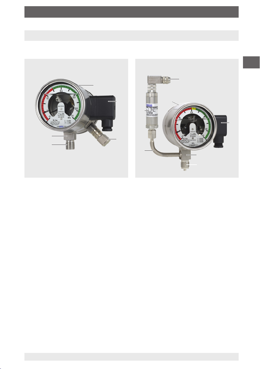
2.1 Overview
Gas density monitor with integrated transmitter
Model GDM-100-TI
Product label
Electrical connection, cable socket
Transmitter
Process connection, spanner flats
Process connection, thread
Gas density monitor with built-in transmitter
Model GDM-100-TA
Electrical connection, transmitter
Electrical connection, switch contacts
Process connection, spanner flats
Process connection, thread
Extension for transmitter
Product label, transmitter
Product label, gas density monitor
EN
2.2 Description
Switch contacts
The switch contacts permanently installed in the gas density monitor close or open at
set limit values, depending on the switching function. Switching functions are: Normally
closed, normally open, change-over contact.
The magnetic snap-action contacts are auxiliary current switches which open or close
connected electric circuits via a contact arm which is moved by the instrument pointer.
2.3 Scope of delivery
Cross-check scope of delivery with delivery note.
14300398.01 04/2019 EN/DE/FR/ES
5WIKA operating instructions, models GDM-100-TI, GDM-100-TA
Page 6

3. Safety
3. Safety
3.1 Explanation of symbols
EN
3.2 Intended use
Wherever the gas density of SF₆ gas has to be indicated locally and, at the same time,
circuits need to be switched, the model GDM-100 gas density monitor finds its use. The
transmitter transmits the measured gas density as an electrical signal.
Gas density monitors are modified contact pressure gauges, specially developed for the
use of SF₆ gas. Temperature influences acting on the enclosed SF₆ gas are compensated by a compensation system.
The gas density monitors are specially designed for the respective application in switch-
gear (pure SF₆ gas, gas mixtures, calibration pressure, switch points ...). Before use,
check whether this instrument is suitable for the intended application.
WARNING!
... indicates a potentially dangerous situation that can result in serious
injury or death, if not avoided.
CAUTION!
... indicates a potentially dangerous situation that can result in light injuries
or damage to property or the environment, if not avoided.
Information
... points out useful tips, recommendations and information for efficient
and trouble-free operation.
Only use the instrument in applications that lie within its technical performance limits
(e.g. max. ambient temperature, material compatibility, ...).
→ For performance limits see chapter 9 “Specifications”.
This instrument is not permitted to be used in hazardous areas!
The instrument has been designed and built solely for the intended use described here,
and may only be used accordingly.
6
WIKA operating instructions, models GDM-100-TI, GDM-100-TA
14300398.01 04/2019 EN/DE/FR/ES
Page 7

3. Safety
The technical specifications contained in these operating instructions must be
observed. Improper handling or operation of the instrument outside of its technical
specifications requires the instrument to be taken out of service immediately and
inspected by an authorised WIKA service engineer.
The manufacturer shall not be liable for claims of any type based on operation contrary
to the intended use.
3.3 Improper use
WARNING!
Injuries through improper use
Improper use of the instrument can lead to hazardous situations and
injuries.
▶
Refrain from unauthorised modifications to the instrument.
▶
Do not use the instrument within hazardous areas.
Any use beyond or different to the intended use is considered as improper use.
3.4 Responsibility of the operator
The instrument is used in the industrial sector. The operator is therefore responsible for
legal obligations regarding safety at work.
The safety instructions within these operating instructions, as well as the safety,
accident prevention and environmental protection regulations for the application area
must be maintained.
EN
The operator is obliged to maintain the product label in a legible condition.
To ensure safe working on the instrument, the operating company must ensure
■
that suitable first-aid equipment is available and aid is provided whenever required.
■
that the operating personnel are regularly instructed in all topics regarding work
safety, first aid and environmental protection and know the operating instructions and
in particular, the safety instructions contained therein.
■
that the instrument is suitable for the particular application in accordance with its
intended use.
■
that personal protective equipment is available.
14300398.01 04/2019 EN/DE/FR/ES
7WIKA operating instructions, models GDM-100-TI, GDM-100-TA
Page 8

3. Safety
3.5 Personnel qualification
WARNING!
Risk of injury should qualification be insufficient
EN
Skilled personnel
Skilled personnel, authorised by the operator, are understood to be personnel who,
based on their technical training, knowledge of measurement and control technology
and on their experience and knowledge of country-specific regulations, current standards and directives, are capable of carrying out the work described and independently
recognising potential hazards.
Specically when using SF₆ gas
The plant operator must ensure that the handling of SF
qualied company or by qualied persons who have been specially trained in accordance with IEC 61634, section 4.3.1 or IEC 60480, section 10.3.1.
3.6 Personal protective equipment
The personal protective equipment is designed to protect the skilled personnel from
hazards that could impair their safety or health during work. When carrying out the
various tasks on and with the instrument, the skilled personnel must wear personal
protective equipment.
Improper handling can result in considerable injury and damage to equipment.
▶
The activities described in these operating instructions may only be
carried out by skilled personnel who have the qualifications described
below.
gas is only carried out by a
6
Follow the instructions displayed in the work area regarding personal protective
equipment!
The requisite personal protective equipment must be provided by the operating company.
Safety goggles in accordance with EN 166, class 2, mechanical
strength class S
The safety goggles must be worn over the entire period when working on
hoses or gas containers (e.g. gas cylinders, tanks).
The safety goggles protect the eyes from any flying particles, escaping
gas and liquid splashes.
Protective gloves against heat in accordance with EN ISO 13732-1
and against cold in accordance with EN ISO 13732-3
The protective gloves must be worn over the entire period when working
on hoses, gas containers (e.g. gas cylinders, tanks) or components which
heat up to over 60 °C.
8
WIKA operating instructions, models GDM-100-TI, GDM-100-TA
14300398.01 04/2019 EN/DE/FR/ES
Page 9

3. Safety
3.7 Handling of insulating gases and gas mixtures
SF₆ gas is a greenhouse gas which is listed in the Kyoto Protocol. SF₆ gas must not be
released into the atmosphere, but must be collected in suitable containers.
Properties of insulating gases
■
Colourless and odourless
■
Chemically neutral
■
Inert
■
Not flammable
■
Heavier than air
■
No toxicity
■
No damage to the ozone layer
Detailed information is given in IEC 60376 and IEC 61634.
Danger of suocation caused by insulating gases and gas mixtures
High concentrations of gases can lead to asphyxiation, since breathable air is displaced
from the lungs with the inhalation of gas.
Since SF₆ gas is heavier than air, it collects, especially, at ground level or lower-lying
rooms below the reference level (e.g. cellars). This is particularly dangerous since SF₆
gas is colourless and odourless and thus may be imperceptible to people.
3.8 Danger caused by decomposition products
Insulating gas in electrical systems may contain decomposition products generated by
electric arcs:
■
Gaseous sulphur fluorides
■
Sulphur hexafluorides
■
Solid and atomized metal fluorides, metal sulfides, metal oxides
■
Hydrogen fluoride
■
Sulphur dioxide
Decomposition products can be harmful to health.
■
They can cause poisoning by inhalation, ingestion or contact with the skin.
■
They may be irritating to the eyes, the respiratory system or the skin and burn them.
■
Inhalation of large quantities may damage the lungs.
EN
Observe the following safety instructions in order to avoid danger from insulating gas:
■
Wear personal protective equipment.
■
Read the material safety data sheet of the gas supplier.
■
With large leaks, evacuate the area quickly.
■
Ensure good ventilation.
■
Ensure the leak tightness of the equipment with a leak detector (e.g. model GIR-10).
14300398.01 04/2019 EN/DE/FR/ES
9WIKA operating instructions, models GDM-100-TI, GDM-100-TA
Page 10

3. Safety
3.9 Applicable standards and directives for installation, assembly, commissioning
■
BGI 753 (SF₆ plants and equipment in Germany)
■
IEC 61634 (Handling of SF₆ gas)
■
IEC 60376 (New SF₆ gas, technical grade SF₆ gas)
■
EN
IEC 60480 (Used SF₆ gas)
■
CIGRE report 276, 2005 (Practical SF₆ gas handling instructions)
Leaks during operation:
■
IEC 60376 (New SF₆ gas, technical grade SF₆ gas)
■
IEC 60480 (Used SF₆ gas)
■
CIGRE 2002 (“SF₆ gas in the electrical industry”)
SF
is a colourless and odourless, chemically neutral, inert and non-am-
6
mable gas which is approx. ve times heavier than air, non-toxic and not
harmful to the ozone layer.
Detailed information is given in IEC 60376 and IEC 61634.
3.10 Labelling, safety marks
Product label (gas density monitor)
Dichtewächter mit Kontakteinrichtung
Density monitor with alarm contacts
Schaltzustand bei Skalenanfangswert / Status of switch at minimum scale value Made in Germany
Model designation
Pin assignment
Case filling
P# Product No.
Date of manufacture
Switching thresholds
Electrical characteristics
Model designation of the switch contact
10
14300398.01 04/2019 EN/DE/FR/ES
WIKA operating instructions, models GDM-100-TI, GDM-100-TA
Page 11

3. Safety / 4. Transport, packaging and storage
Product label (transmitter)
Model designation
Measuring range
Output signal
Power supply
S# Article No.
P# Product No.
Pin assignment
Date of manufacture
EN
4. Transport, packaging and storage
4.1 Transport
Check the instrument for any damage that may have been caused by transport.
Obvious damage must be reported immediately.
CAUTION!
Damage through improper transport
With improper transport, a high level of damage to property can occur.
▶
When unloading packed goods upon delivery as well as during internal
transport, proceed carefully and observe the symbols on the packaging.
▶
With internal transport, observe the instructions in chapter 4.2 “Packaging and storage”.
4.2 Packaging and storage
Do not remove packaging until just before mounting.
Keep the packaging as it will provide optimum protection during transport (e.g. change
in installation site, sending for repair).
14300398.01 04/2019 EN/DE/FR/ES
11WIKA operating instructions, models GDM-100-TI, GDM-100-TA
Page 12

4.Transport, ... / 5. Commissioning, operation
WARNING!
Physical injuries and damage to property and the environment
caused by hazardous decomposition products
Before storing the instrument, any residual decomposition products must
EN
Permissible conditions at the place of storage:
■
Storage temperature: -40 ... +60 °C
■
Humidity: 45 ... 75 % r.h. (non-condensing)
Avoid exposure to the following factors:
■
Soot, vapour, dust and corrosive gases
■
Hazardous environments, flammable atmospheres
Store the instrument in its original packaging in a location that fulfils the conditions
listed above. If the original packaging is not available, pack and store the instrument as
described below:
1. Place the instrument, along with the shock-absorbent material, in the packaging.
2. If stored for a prolonged period of time (more than 30 days), place a bag containing
a desiccant inside the packaging.
be removed.
▶
For cleaning, see chapter 7.2 “Cleaning”
5. Commissioning, operation
5.1 Mechanical mounting
CAUTION!
Physical injuries and damage to property and the environment
through faulty instrument
Prior to commissioning, the instrument must be subjected to a visual
inspection. Only use the instrument if it is in perfect condition with respect
to safety.
5.1.1 Requirements for the installation point
■
For outdoor applications, the selected installation location has to be suitable for the
specified ingress protection, so that the instrument is not exposed to impermissible
weather conditions.
■
The sealing faces at the instrument and at the measuring point have to be undamaged and clean.
12
WIKA operating instructions, models GDM-100-TI, GDM-100-TA
14300398.01 04/2019 EN/DE/FR/ES
Page 13
5. Commissioning, operation
5.1.2 Installation
■
With transport or storage, it can occur that gas density monitors warm up or cool down
and this results in pointer movements. These pointer movements are caused by the
compensation system. To make sure that the instruments have adapted sufficiently to
ambient temperature, at least 2 hours at 20 °C must be allowed for adaptation to the
temperature. Then, in the depressurised state, the pointer will sit within the tolerance
bar.
■
Corresponding to the general technical rules for pressure gauges (e.g. EN 837-2
“Selection and installation recommendations for pressure gauges”) when screwing in
the instrument, the force required to do this must not be applied through the case, but
only through the spanner flats provided for this purpose and using a suitable tool.
■
When screwing in, do not tilt the threads.
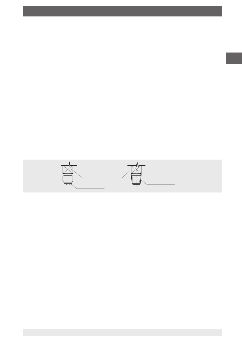
For parallel threads, use flat gaskets, lens-type sealing rings or WIKA profile sealings
at the sealing face . With tapered threads (e.g. NPT threads), sealing is made in the
threads , using a suitable sealing material (EN 837-2).
The tightening torque depends on the sealing used. In order to orientate the measuring
instrument so that it can be read as well as possible, a connection with LH-RH union or
union nut should be used. When a blow-out device is fitted to an instrument, it must be
protected against being blocked by debris and dirt.
Spanner ats
Sealing face
Sealing in the thread
EN
5.1.3 Temperature load
The installation of the instrument should be made in such a way that the permissible
operating temperature, also considering the effects of convection and thermal radiation,
neither exceeds nor falls below the permissible limits.
The influence of temperature on the indication and measurement accuracy must be
observed.
5.2 Electrical mounting of the gas density monitor
■
The instrument must be grounded via the process connection.
■
For cable outlets, make sure that no moisture enters at the cable end.
■
Select a cable diameter that matches the cable bushing of the connector. Make sure
that the cable gland of the mounted plug has a tight fit and that the seals are present
and undamaged. Tighten the threaded connection and check that the sealing is
correctly seated, in order to ensure the ingress protection.
■
Connection details and switching functions are given on the product label. Connection terminals and ground terminal are appropriately marked.
14300398.01 04/2019 EN/DE/FR/ES
13WIKA operating instructions, models GDM-100-TI, GDM-100-TA
Page 14

5. Commissioning, operation
5.2.1 Limit values for the contact load with resistive load
gas-filled instruments liquid-filled instruments
EN
Maximum rated operating
voltage Ueff
Rated operating current
Switch-on current 1 A 1 A
Switch-off current 1 A 1 A
Continuous current 0.6 A 0.6 A
Maximum switching power 30 W, 50 VA 20 W, 20 VA
Do not exceed the limit values. In order to permanently ensure safe operation, the
following load values are recommended:
AC 250 V AC 250 V
Voltage
gas-filled instruments liquid-filled instruments
(per IEC 38)
resistive load inductive
load
DC/AC DC AC cos ϕ >0.7 DC AC cos ϕ >0.7
230 V 100 mA 120 mA 65 mA 65 mA 90 mA 40 mA
110 V 200 mA 240 mA 130 mA 130 mA 180 mA 85 mA
48 V 300 mA 450 mA 200 mA 190 mA 330 mA 130 mA
24 V 400 mA 600 mA 250 mA 250 mA 450 mA 150 mA
resistive load inductive load
The switching current must not be less than 20 mA with low voltages for switching reliability reasons.
For higher loads, and for instruments with liquid-lled cases, WIKA model
905.1X contact protection relays are recommended
Overcurrent protectors
The instruments do not provide for incorporated overcurrent protectors. Should protectors be required, the following values in accordance with EN 60 947-5-1 are to be
recommended.
■
Voltage 24 V: 2 A
■
Voltage 250 V: 1 A
14
WIKA operating instructions, models GDM-100-TI, GDM-100-TA
14300398.01 04/2019 EN/DE/FR/ES
Page 15

5. Commissioning, operation
5.2.2 Contact protection measures
Mechanical contacts must not exceed the specified electrical values for switching
current, switching voltage and switching power independent of each other, not even for
a short time only.
For capacitive or inductive loads we recommend one of the following protective circuits:
Inductive load with DC voltage
With DC voltage the contact protection can be achieved via a free-wheeling diode,
connected in parallel to the load. The polarity of the diode must be arranged so that it
closes when the operating voltage is on.
Example:
Contact protection
measure with freewheeling diode
Contact
EN
Diode
Load
Inductive load with AC voltage
With AC voltage two protection measures are possible:
Example:
Contact protection
measure with
voltage-dependent
resistor VDR
Example:
Contact protection
measure with RC
element
Load
Load
14300398.01 04/2019 EN/DE/FR/ES
15WIKA operating instructions, models GDM-100-TI, GDM-100-TA
Page 16

U
U
+
-
U
A
UB+/Sig+
0V/Sig-
5. Commissioning, operation
Capacitive load
With capacitive loads elevated switch-on currents arise. These can be reduced by
series-connecting resistors in the supply line.
EN
Examples: Contact protection measure with current-limiting resistor
B
R
1
Load Load
B
R
1
5.3 Electrical mounting of the transmitter
Requirements for voltage supply
Power supply: DC 10 ... 30 V
The supply must be made via an energy-limited circuit in accordance with IEC 61010-1.
Requirements for electrical connection
■
Cable diameter matches the cable bushing of the mating connector.
■
Cable gland and seals of the mating connector are correctly seated.
■
With cable outlets, no humidity can ingress at the cable end.
Requirement for shielding and grounding
The transmitter is grounded via the process connection of the gas density monitor. The
transmitter is connected with the process connection of the gas density monitor via the
mounting.
Pin assignment
Transmitter, angular connector (2-pin)
16
WIKA operating instructions, models GDM-100-TI, GDM-100-TA
14300398.01 04/2019 EN/DE/FR/ES
Page 17

5. Commissioning, operation / 6. Faults
5.4 Switch point setting
The switch points have a fixed setting as standard and cannot be adjusted. Thus, an
undesired adjustment of the switch points is excluded.
With customer-specific, adjustable switch points, with the accompanying adjustment
key, the desired set point can be set via the adjustment lock in the window.
6. Faults
CAUTION!
Physical injuries and damage to property and the environment
If faults cannot be eliminated by means of the listed measures, the instrument must be taken out of operation immediately.
▶
Ensure that pressure or signal is no longer present and protect against
accidental commissioning.
▶
Contact the manufacturer.
▶
If a return is needed, please follow the instructions given in chapter 9.2
“Return”.
EN
For contact details see chapter 1 “General information” or the back page
of the operating instructions.
14300398.01 04/2019 EN/DE/FR/ES
17WIKA operating instructions, models GDM-100-TI, GDM-100-TA
Page 18

EN
6. Faults
Faults Causes Measures
Contact is no longer
switching in line with the
specification
Switching status remains
unchanged despite
reaching the switch point/
reset point
No pointer movement
despite change in pressure
Pointer movement, even
though depressurised
No output signal Cable break Replace connection cable
Deviating zero point signal Overpressure limit exceeded Observe the permissible
Constant output signal
upon change in pressure
Signal span varies EMC interference sources in
Signal span varies/
inaccurate
Signal span drops/too
small
Electrical connection is
interrupted.
Electrical load unsuitable for
the switch contact model.
Contact contaminated.
Contacts defective (e.g. fused
contact zone).
Movement blocked. Replace instrument.
Warming or cooling of the
measuring instrument (no
damage)
Too high/low working temperature
Mechanical overload caused
by overpressure
the environment; for example,
frequency converter
Too high/low working
temperature
Mechanical overload caused
by overpressure
Carry out a continuity test on
the electrical connection lines.
Maintain the permissible
electrical loads for the switch
contact model.
Replace instrument. Before
recommissioning the
new instrument, provide
a protective circuit for the
contact.
Let the instrument settle for 2
hours at 20 °C.
overpressure limit
Observe the permissible
temperatures
Replace instrument; if it
fails repeatedly, contact the
manufacturer
Shield instrument; cable
shield; remove source of
interference
Observe the permissible
temperatures
Replace instrument; if it
fails repeatedly, contact the
manufacturer
For claims, the serial and product numbers must be stated. The serial number is printed
on the dial, the product number on the product label. With claims, the atmospheric
pressure and the temperature during the measurement must be given, as well as the
data on the reference standard (model, class).
18
WIKA operating instructions, models GDM-100-TI, GDM-100-TA
14300398.01 04/2019 EN/DE/FR/ES
Page 19

7. Maintenance, cleaning and recalibration
7. Maintenance, cleaning and recalibration
7.1 Maintenance
These gas density monitors are maintenance-free.
The indication and switching function should be checked once or twice every year. For
this the instrument must be disconnected from the gas compartment to check with a
pressure testing device.
Repairs must only be carried out by the manufacturer.
The instruments must not be opened, since this can lead to indication and switch point
errors.
7.2 Cleaning
CAUTION!
Physical injuries and damage to property and the environment
Improper cleaning may lead to physical injuries and damage to property
and the environment. Decomposition products in the dismounted instrument can result in a risk to persons, the environment and equipment.
▶
Carry out the cleaning process as described below.
1. Before cleaning, correctly disconnect the instrument from the pressure supply and
switch o the current.
2. Use the requisite protective equipment.
3. Clean the instrument with a moist cloth.
Electrical connections must not come into contact with moisture!
EN
CAUTION!
Damage to the instrument
Improper cleaning may lead to damage to the instrument!
▶
Do not use any aggressive cleaning agents.
▶
Do not use any hard or pointed objects for cleaning.
4. Wash or clean the dismounted instrument, in order to protect people and the environment from exposure to residual decomposition products.
Information on returns can be found under the heading “Service” on our
local website.
7.3 Calibration
The gas density monitor can be calibrated via a special calibration system for gas densi-
ty measuring instruments (e.g. WIKA BCS-10).
The gas density monitor must be dismounted professionally. In this case, it may be
necessary to take the entire system temporarily out of service.
14300398.01 04/2019 EN/DE/FR/ES
19WIKA operating instructions, models GDM-100-TI, GDM-100-TA
Page 20

8. Dismounting, return and disposal
8. Dismounting, return and disposal
8.1 Dismounting
EN
Before dismantling the instrument, evacuate the gas filling.
Only dismount the instrument when it is depressurised and free from current.
8.2 Return
When returning the instrument, use the original packaging or a suitable transport
packaging.
To avoid damage:
1. Place the instrument, along with the shock-absorbent material, in the packaging.
Place shock-absorbent material evenly on all sides of the transport packaging.
2. If possible, place a bag containing a desiccant inside the packaging.
WARNING!
Physical injuries and damage to property and the environment
caused by hazardous decomposition products
Upon contact with hazardous decomposition products, there is a danger
of physical injuries and damage to property and the environment.
▶
Wear the requisite protective equipment (see chapter 3.6 “Personal
protective equipment”).
WARNING!
Strictly observe the following when shipping the instrument:
All instruments delivered to WIKA must be free from any kind of hazard-
ous substances (e.g. decomposition products) and must therefore be
cleaned before being returned.
Information on returns can be found under the heading “Service” on our
local website.
8.3 Disposal
Incorrect disposal can put the environment at risk.
Dispose of instrument components and packaging materials in an environmentally
compatible way and in accordance with the country-specific waste disposal regulations.
20
WIKA operating instructions, models GDM-100-TI, GDM-100-TA
14300398.01 04/2019 EN/DE/FR/ES
Page 21

9. Specifications
9. Specifications
Measuring ranges
Nominal size in mm 100
Measuring range Vacuum and overpressure range with measuring span of 1.6 ... 25 bar
(at an ambient temperature of 20 °C and gaseous phase)
Pressure element
Leak rate ≤ 1 · 10 -8 mbar · l / s
Test method Helium mass spectrometry
Output signals
Output signal 4 ... 20 mA, 2-wire
Permissible max. load
R
A
Switch contacts
Number of contacts Max. 4 magnetic snap-action contacts
Switching function Normally open, normally closed, change-over contact (max. 2 switch
Switch point setting secured switch points, not adjustable (option: Adjustable switch
Switching power For cases with gas filling: 30 W / 50 VA, max. 1 A
RA ≤ (UB - 10 V) / 0.02 A with RA in ohms and UB in volts
points)
points)
With cases with filling liquid: 20 W / 20 VA, max. 1 A
EN
Voltage supply
Power supply DC 10 ... 30 V
Accuracy specifications
Mechanical display ±1 % at an ambient temperature of 20 °C [68 °F]
±2.5 % at an ambient temperature of -20 … +60 °C and with
calibration pressure in accordance with reference isochore (reference
diagram KALI-Chemie AG, Hanover, prepared by Dr. Döring 1979)
Transmitter
Point of optimal
density
14300398.01 04/2019 EN/DE/FR/ES
-40 °C: 3 % of span
20 °C: 1 % of span
60 °C: 2.3 % of span
21WIKA operating instructions, models GDM-100-TI, GDM-100-TA
Page 22

9. Specifications
Accuracy specifications
Start and end of the
measuring range
EN
Stability per year ≤ 0.3 % of span
Switch contacts Switching accuracy in the temperature range -20 … +60 °C
Operating conditions
Permissible temperature range
Ambient -20 ... +60 °C (gaseous phase)
Storage -40 ... +60 °C
Ingress protection per
IEC/EN 60529
Intended medium pure SF
High-voltage test 100 % 2 kV, 50 Hz, 1 s (wiring against case)
Electromagnetic
compatibility (EMC) to
IEC 61000-4
-40 °C: 4 % of span
20 °C: 2 % of span
60 °C: 3.3 % of span
Switch point = calibration pressure P
specification
Switch point ≠ calibration pressure PE: Parallel to the reference iso-
chore of the calibration pressure
IP65
gas, further gas mixtures on request
6
IEC 61000-4-2 (ESD): Test level 4 (8 kV)
IEC 61000-4-3 (Field): Test level 3 (10 V/m)
IEC 61000-4-4 (Burst): Test level X (±2 kV)
IEC 61000-4-5 (Surge): Test level 2 (±1 kV)
IEC 61000-4-6 (Conducted RFI): Test level 3 (10 V)
: In accordance with customer
E
Process connections
Process connection G ½ B per EN 837, lower mount
Spanner flats 22 mm
(Option: Flange connection)
other connections and connection locations on request
Electrical connection
Switch contacts Cable socket with M20 x 1.5 cable gland
Wire cross-section max. 2.5 mm²
(Option: Plug-in cable box)
Transmitter With built-in transmitter: Cable outlet
With built-in transmitter: Angular connector (2-pin), IP67 (option:
Field case, stainless steel, IP67)
Electrical safety Protection against reverse polarity and overvoltage
22
WIKA operating instructions, models GDM-100-TI, GDM-100-TA
14300398.01 04/2019 EN/DE/FR/ES
Page 23

9. Specifications
Materials
Movement Stainless steel
Bimetal link (temperature compensation)
Dial Aluminium, red, yellow, green area as specified in the order
Pointer Aluminium, black
Case Stainless steel, with silicone oil or nitrogen filling
Gas-tight: Leak rate ≤ 1 · 10-5 mbar · l / s
Switch contacts 80 % Ag / 20 % Ni, gold-plated
Transmitter Stainless steel
Window Laminated safety glass (option: Clear non-splintering plastic win-
dow)
Ring Bayonet ring, stainless steel, secured by means of 3 welding
spots
Process connection Stainless steel
Internal transmission
fluid
Media chamber with pro-
cess connection (wetted)
Pressure element Stainless steel, welded
Synthetic oil
Stainless steel 316Ti (1.4571)
EN
Approvals
Logo Description Country
EU declaration of conformity
■
EMC directive
■
Pressure equipment directive
■
Low voltage directive
EAC
■
EMC directive
■
Pressure equipment directive
■
Low voltage directive
■
Machinery directive
■
Gas appliances directive
For further specifications, see the order documentation.
14300398.01 04/2019 EN/DE/FR/ES
European Union
Eurasian Economic
Community
23WIKA operating instructions, models GDM-100-TI, GDM-100-TA
Page 24
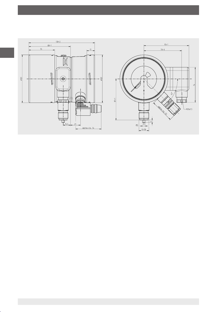
9. Specifications
Dimensions in mm
EN
Weight: approx. 1.2 kg
24
WIKA operating instructions, models GDM-100-TI, GDM-100-TA
14300398.01 04/2019 EN/DE/FR/ES
Page 25

Inhalt
Inhalt
1. Allgemeines 26
2. Aufbau und Funktion 27
3. Sicherheit 28
4. Transport, Verpackung und Lagerung 33
5. Inbetriebnahme, Betrieb 34
6. Störungen 39
7. Wartung, Reinigung und Rekalibrierung 41
8. Demontage, Rücksendung und Entsorgung 42
9. Technische Daten 43
Konformitätserklärungen finden Sie online unter www.wika.de.
DE
14300398.01 04/2019 EN/DE/FR/ES
25WIKA Betriebsanleitung, Typen GDM-100-TI, GDM-100-TA
Page 26

1. Allgemeines
1. Allgemeines
■
Das in der Betriebsanleitung beschriebene Gerät wird nach dem aktuellen Stand der
Technik konstruiert und gefertigt. Alle Komponenten unterliegen während der Fertigung strengen Qualitäts- und Umweltkriterien. Unsere Managementsysteme sind
nach ISO 9001 und ISO 14001 zertifiziert.
DE
■
Diese Betriebsanleitung gibt wichtige Hinweise zum Umgang mit dem Gerät.
Voraussetzung für sicheres Arbeiten ist die Einhaltung aller angegebenen
Sicherheitshinweise und Handlungsanweisungen.
■
Die für den Einsatzbereich des Gerätes geltenden örtlichen
Unfallverhütungsvorschriften und allgemeinen Sicherheitsbestimmungen einhalten.
■
Die Betriebsanleitung ist Produktbestandteil und muss in unmittelbarer Nähe des
Gerätes für das Fachpersonal jederzeit zugänglich aufbewahrt werden. Betriebsanleitung an nachfolgende Benutzer oder Besitzer des Gerätes weitergeben.
■
Das Fachpersonal muss die Betriebsanleitung vor Beginn aller Arbeiten sorgfältig
durchgelesen und verstanden haben.
■
Es gelten die allgemeinen Geschäftsbedingungen in den Verkaufsunterlagen.
■
Technische Änderungen vorbehalten.
■
Weitere Informationen:
- Internet-Adresse: www.wika.de / www.wika.com
- zugehörige Datenblätter:
SP 60.05 Typ GDM-100-TI
SP 60.06 Typ GDM-100-TA
- Anwendungsberater: Tel.: +49 9372 132-0
Fax: +49 9372 132-406
info@wika.de
26
WIKA Betriebsanleitung, Typen GDM-100-TI, GDM-100-TA
14300398.01 04/2019 EN/DE/FR/ES
Page 27

2. Aufbau und Funktion
2. Aufbau und Funktion
2.1 Überblick
Gasdichtewächter mit integriertem Transmitter
Typ GDM-100-TI
Typenschild
Elektrischer Anschluss, Kabeldose
Transmitter
Prozessanschluss, Schlüsselfläche
Prozessanschluss, Gewinde
Gasdichtewächter mit angebautem Transmitter
Typ GDM-100-TA
Elektrischer Anschluss, Transmitter
Elektrischer Anschluss, Schaltkontakte
Prozessanschluss, Schlüsselfläche
Prozessanschluss, Gewinde
Anbau für Transmitter
Typenschild, Transmitter
Typenschild, Gasdichtewächter
DE
2.2 Beschreibung
Schaltkontakte
Die im Gasdichtewächter fest eingebauten Schaltkontakte schließen oder öffnen
bei eingestellten Grenzwerten je nach Schaltfunktion. Schaltfunktionen sind: Öffner,
Schließer, Wechsler.
Die Magnetspringkontakte sind Hilfsstromschalter, die angeschlossene elektrische
Stromkreise über einen vom Gerätezeiger bewegten Kontaktarm öffnen oder schließen.
2.3 Lieferumfang
Lieferumfang mit dem Lieferschein abgleichen.
14300398.01 04/2019 EN/DE/FR/ES
27WIKA Betriebsanleitung, Typen GDM-100-TI, GDM-100-TA
Page 28

3. Sicherheit
3. Sicherheit
3.1 Symbolerklärung
WARNUNG!
... weist auf eine möglicherweise gefährliche Situation hin, die zum Tod
DE
3.2 Bestimmungsgemäße Verwendung
Überall dort, wo die Gasdichte von SF₆-Gas vor Ort angezeigt werden muss und gleichzeitig Stromkreise geschaltet werden sollen, findet der Gasdichtewächter Typ GDM-100
seinen Einsatz. Der Transmitter überträgt die gemessene Gasdichte als elektrisches
Signal.
Gasdichtewächter sind abgewandelte Kontaktmanometer, die speziell für die Verwen-
dung von SF₆-Gas entwickelt wurden. Temperatureinflüsse die auf das eingeschlossene
SF₆-Gas wirken, werden durch ein Kompensationssystem ausgeglichen.
oder zu schweren Verletzungen führen kann, wenn sie nicht gemieden
wird.
VORSICHT!
... weist auf eine möglicherweise gefährliche Situation hin, die zu geringfügigen oder leichten Verletzungen bzw. Sach- und Umweltschäden führen
kann, wenn sie nicht gemieden wird.
Information
... hebt nützliche Tipps und Empfehlungen sowie Informationen für einen
effizienten und störungsfreien Betrieb hervor.
Die Gasdichtewächter sind speziell für den jeweiligen Einsatzfall in der Schaltanlage
ausgelegt (reines SF₆-Gas, Gasgemische, Eichdruck, Schaltpunkte ...). Vor der Verwendung überprüfen, ob das vorliegende Gerät für den vorgesehenen Einsatzfall geeignet
ist.
Das Gerät nur in Anwendungen verwenden, die innerhalb seiner technischen Leistungs-
grenzen liegen (z. B. max. Umgebungstemperatur, Materialverträglichkeit, ...).
→ Leistungsgrenzen siehe Kapitel 9 „Technische Daten“.
Dieses Gerät ist nicht für den Einsatz in explosionsgefährdeten Bereichen zugelassen!
Das Gerät ist ausschließlich für den hier beschriebenen bestimmungsgemäßen
Verwendungszweck konzipiert und konstruiert und darf nur dementsprechend verwendet werden.
28
WIKA Betriebsanleitung, Typen GDM-100-TI, GDM-100-TA
14300398.01 04/2019 EN/DE/FR/ES
Page 29

3. Sicherheit
Die technischen Spezifikationen in dieser Betriebsanleitung sind einzuhalten. Eine
unsachgemäße Handhabung oder ein Betreiben des Gerätes außerhalb der technischen Spezifikationen macht die sofortige Stilllegung und Überprüfung durch einen
autorisierten WIKA-Servicemitarbeiter erforderlich.
Ansprüche jeglicher Art aufgrund von nicht bestimmungsgemäßer Verwendung sind
ausgeschlossen.
3.3 Fehlgebrauch
WARNUNG!
Verletzungen durch Fehlgebrauch
Fehlgebrauch des Gerätes kann zu gefährlichen Situationen und Verletzungen führen.
▶
Eigenmächtige Umbauten am Gerät unterlassen.
▶
Gerät nicht in explosionsgefährdeten Bereichen einsetzen.
Jede über die bestimmungsgemäße Verwendung hinausgehende oder andersartige
Benutzung gilt als Fehlgebrauch.
3.4 Verantwortung des Betreibers
Das Gerät wird im gewerblichen Bereich eingesetzt. Der Betreiber unterliegt daher den
gesetzlichen Pflichten zur Arbeitssicherheit.
DE
Die Sicherheitshinweise dieser Betriebsanleitung, sowie die für den Einsatzbereich des
Gerätes gültigen Sicherheits-, Unfallverhütungs- und Umweltschutzvorschriften einhalten.
Der Betreiber ist verpflichtet das Typenschild lesbar zu halten.
Für ein sicheres Arbeiten am Gerät muss der Betreiber sicherstellen,
■
dass eine entsprechende Erste-Hilfe-Ausrüstung vorhanden ist und bei Bedarf jederzeit Hilfe zur Stelle ist.
■
dass das Bedienpersonal regelmäßig in allen zutreffenden Fragen von Arbeitssicherheit, Erste Hilfe und Umweltschutz unterwiesen wird, sowie die Betriebsanleitung
und insbesondere die darin enthaltenen Sicherheitshinweise kennt.
■
dass das Gerät gemäß der bestimmungsgemäßen Verwendung für den
Anwendungsfall geeignet ist.
■
dass die persönliche Schutzausrüstung verfügbar ist.
14300398.01 04/2019 EN/DE/FR/ES
29WIKA Betriebsanleitung, Typen GDM-100-TI, GDM-100-TA
Page 30

3. Sicherheit
3.5 Personalqualifikation
WARNUNG!
Verletzungsgefahr bei unzureichender Qualifikation
Unsachgemäßer Umgang kann zu erheblichen Personen- und Sachschäden führen.
▶
DE
Fachpersonal
Das vom Betreiber autorisierte Fachpersonal ist aufgrund seiner fachlichen Ausbildung,
seiner Kenntnisse der Mess- und Regelungstechnik und seiner Erfahrungen sowie
Kenntnis der landesspezifischen Vorschriften, geltenden Normen und Richtlinien in der
Lage, die beschriebenen Arbeiten auszuführen und mögliche Gefahren selbstständig zu
erkennen.
Speziell beim Einsatz von SF₆-Gas
Der Betreiber muss sicherstellen, dass die Handhabung von SF
qualiziertes Unternehmen oder von gemäß IEC 61634 Abschnitt 4.3.1 bzw. IEC 60480
Abschnitt 10.3.1 geschulten Mitarbeitern durchgeführt wird.
3.6 Persönliche Schutzausrüstung
Die persönliche Schutzausrüstung dient dazu, das Fachpersonal gegen Gefahren
zu schützen, die dessen Sicherheit oder Gesundheit bei der Arbeit beeinträchtigen
könnten. Beim Ausführen der verschiedenen Arbeiten an und mit dem Gerät muss das
Fachpersonal persönliche Schutzausrüstung tragen.
Die in dieser Betriebsanleitung beschriebenen Tätigkeiten nur durch
Fachpersonal nachfolgend beschriebener Qualifikation durchführen
lassen.
-Gas durch ein hierzu
6
Im Arbeitsbereich angebrachte Hinweise zur persönlichen Schutzausrüstung
befolgen!
Die erforderliche persönliche Schutzausrüstung muss vom Betreiber zur Verfügung
gestellt werden.
Schutzbrille nach EN 166 Klasse 2, mechanische Festigkeit Klasse S
Die Schutzbrille muss bei Arbeiten an Schläuchen oder Gasbehältern (z.
B. Gaszylinder, Tanks) über die gesamte Dauer hinweg getragen werden.
Die Schutzbrille schützt die Augen vor umherfliegenden Teilen, austretendem Gas und Flüssigkeitsspritzern.
Schutzhandschuhe gegen Wärme nach EN ISO 13732-1 und gegen
Kälte nach EN ISO 13732-3
Die Schutzhandschuhe müssen bei Arbeiten an Schläuchen, Gasbehältern (z. B. Gaszylinder, Tanks) oder Teilen die sich auf über 60 °C erwärmen über die gesamte Dauer hinweg getragen werden.
30
WIKA Betriebsanleitung, Typen GDM-100-TI, GDM-100-TA
14300398.01 04/2019 EN/DE/FR/ES
Page 31

3. Sicherheit
3.7 Umgang mit Isoliergasen und Gasgemischen
SF₆-Gas ist ein Treibhausgas, das im Kyoto-Protokoll gelistet ist. Das SF₆-Gas darf
nicht in die Atmosphäre gelangen, sondern muss in geeigneten Behältern gesammelt
werden.
Eigenschaften von Isoliergasen
■
Farb- und geruchlos
■
Chemisch neutral
■
Inert
■
Nicht entflammbar
■
Schwerer als Luft
■
Keine Toxizität
■
Nicht ozonschädigend
Detaillierte Angaben benden sich in der IEC 60376 und IEC 61634.
Erstickungsgefahr durch Isoliergase und Gasgemische
Hohe Konzentrationen von Gasen können zur Erstickung führen, da beim Einatmen von
Gas die Atemluft aus den Lungen verdrängt wird.
Da SF₆-Gas schwerer ist als Luft, sammelt es sich insbesondere in Bodennähe oder
tiefer gelegenen Räumen unterhalb des Bezugsniveaus an (z. B. Kellerräume). Dies ist
besonders gefährlich, da SF6-Gas farb- und geruchlos ist und somit vom Menschen
nicht wahrgenommen wird.
3.8 Gefährdung duch Zersetzungsprodukte
Isoliergas in elektrischen Anlagen kann durch Lichtbogeneinwirkung Zersetzungsprodukte enthalten:
■
Gasförmige Schwefelflouride
■
Schwefeloxyfluoride
■
Feste staubförmige Metallfluoride, -sulfide und -oxide
■
Fluorwasserstoff
■
Schwefeldioxid
DE
Zersetzungsprodukte können gesundheitsschädlich sein.
■
Durch Einatmen, Verschlucken oder Hautberührung kann es zu einer Vergiftung
kommen.
■
Augen, Atmungsorgane oder die Haut kann gereizt und verätzt werden.
■
Durch Einatmen größerer Mengen kann die Lunge geschädigt werden.
Folgende Sicherheitshinweise beachten, um Gefahren durch Isoliergas zu vermeiden:
■
Persönliche Schutzausrüstung tragen.
■
Das Sicherheitsdatenblatt des Gaslieferanten lesen.
■
Bei großen Leckagen schnell den Ort verlassen.
■
Für gute Belüftung sorgen.
■
Dichtigkeit der Betriebsmittel mit Lecksuchgerät sicherstellen (z. B. Typ GIR-10).
14300398.01 04/2019 EN/DE/FR/ES
31WIKA Betriebsanleitung, Typen GDM-100-TI, GDM-100-TA
Page 32

3. Sicherheit
3.9 Geltende Normen und Richtlinien für Installation, Errichtung, Inbetriebnahme
■
BGI 753 (SF₆-Anlagen und Betriebsmittel in Deutschland)
■
IEC 61634 (Handhabung von SF₆-Gas)
■
IEC 60376 (neues SF6-Gas, technisches SF₆-Gas)
■
IEC 60480 (gebrauchtes SF₆-Gas)
■
CIGRE report 276, 2005 (Practial SF₆ gas handling instructions)
DE
Leckagen während des Betriebs:
■
IEC 60376 (neues SF₆-Gas, technisches SF₆-Gas)
■
IEC 60480 (gebrauchtes SF₆-Gas)
■
CIGRE 2002 („SF₆ gas in the electrical industry“)
SF
-Gas ist farb- und geruchlos, chemisch neutral, inert, nicht entamm-
6
bar und etwa fünfmal schwerer als Luft, nicht toxisch und nicht ozonschädigend.
Detaillierte Angaben benden sich in der IEC 60376 und IEC 61634.
3.10 Beschilderung, Sicherheitskennzeichnungen
Typenschild (Gasdichtewächter)
Schaltzustand bei Skalenanfangswert / Status of switch at minimum scale value Made in Germany
Typbezeichnung
Anschlussbelegung
Gehäusefüllung
P# Erzeugnis-Nr.
Herstelldatum
Schaltschwellen
Elektrische Kennwerte
Typbezeichnung des Schaltkontakts
32
Dichtewächter mit Kontakteinrichtung
Density monitor with alarm contacts
WIKA Betriebsanleitung, Typen GDM-100-TI, GDM-100-TA
14300398.01 04/2019 EN/DE/FR/ES
Page 33

3. Sicherheit / 4.Transport, Verpackung und Lagerung
Typenschild (Transmitter)
Typbezeichnung
Messbereich
Ausgangssignal
Hilfsenergie
S# Artikel-Nr.
P# Erzeugnis-Nr.
Anschlussbelegung
Herstelldatum
DE
4. Transport, Verpackung und Lagerung
4.1 Transport
Gerät auf eventuell vorhandene Transportschäden untersuchen.
Offensichtliche Schäden unverzüglich mitteilen.
VORSICHT!
Beschädigungen durch unsachgemäßen Transport
Bei unsachgemäßem Transport können Sachschäden in erheblicher Höhe
entstehen.
▶
Beim Abladen der Packstücke bei Anlieferung sowie innerbetrieblichem
Transport vorsichtig vorgehen und die Symbole auf der Verpackung
beachten.
▶
Bei innerbetrieblichem Transport die Hinweise unter Kapitel 4.2 „Verpackung und Lagerung“ beachten.
4.2 Verpackung und Lagerung
Verpackung erst unmittelbar vor der Montage entfernen.
Die Verpackung aufbewahren, denn diese bietet bei einem Transport einen optimalen
Schutz (z. B. wechselnder Einbauort, Reparatursendung).
14300398.01 04/2019 EN/DE/FR/ES
33WIKA Betriebsanleitung, Typen GDM-100-TI, GDM-100-TA
Page 34

4.Transport, ... / 5. Inbetriebnahme, Betrieb
WARNUNG!
Körperverletzungen, Sach- und Umweltschäden durch gefährliche
Zersetzungsprodukte
Vor der Einlagerung müssen alle anhaftenden Zersetzungsprodukte
entfernt werden.
▶
Reinigung siehe Kapitel 7.2 „Reinigung“
DE
Zulässige Bedingungen am Lagerort:
■
Lagertemperatur: -40 ... +60 °C
■
Feuchtigkeit: 45 ... 75 % r. F. (nicht kondensierend)
Folgende Einflüsse vermeiden:
■
Ruß, Dampf, Staub und korrosive Gase
■
Explosionsgefährdete Umgebung, entzündliche Atmosphären
Das Gerät in der Originalverpackung an einem Ort lagern, der die oben gelisteten
Bedingungen erfüllt. Wenn die Originalverpackung nicht vorhanden ist, dann das Gerät
wie folgt verpacken und lagern:
1. Das Gerät mit dem Dämmmaterial in der Verpackung platzieren.
2. Bei längerer Einlagerung (mehr als 30 Tage) einen Beutel mit Trocknungsmittel der
Verpackung beilegen.
5. Inbetriebnahme, Betrieb
5.1 Mechanische Montage
VORSICHT!
Körperverletzungen, Sach- und Umweltschäden durch defektes
Gerät
Vor der Inbetriebnahme das Gerät optisch prüfen. Das Gerät nur in
sicherheitstechnisch einwandfreiem Zustand einsetzen.
5.1.1 Anforderungen an die Einbaustelle
■
Bei Anwendungen im Freien ist ein für die angegebene Schutzart geeigneter Aufstellort zu wählen, damit das Gerät keinen unzulässigen Witterungseinflüssen ausgesetzt
ist.
■
Dichtflächen am Gerät und an der Messstelle müssen unbeschädigt und frei von
Verschmutzungen sein.
5.1.2 Installation
■
Beim Transport oder der Lagerung kann es vorkommen, dass sich Gasdichtewächter
erwärmen oder abkühlen und dies in Zeigerbewegungen resultiert. Diese Zeigerbewegungen werden durch das Kompensationssystem hervorgerufen. Um sicherzustellen, dass sich die Geräte ausreichend der Umgebungstemperatur angepasst haben,
müssen sie min. 2 Std. bei 20 °C temperiert werden. Danach steht der Zeiger im
drucklosen Zustand innerhalb des Toleranzbalkens.
34
WIKA Betriebsanleitung, Typen GDM-100-TI, GDM-100-TA
14300398.01 04/2019 EN/DE/FR/ES
Page 35

5. Inbetriebnahme, Betrieb
■
Entsprechend den allgemeinen technischen Regeln für Manometer (z.B. EN 837-2
„Auswahl und Einbauempfehlungen für Druckmessgeräte“) darf beim Einschrauben des Gerätes die dazu erforderliche Kraft nicht über das Gehäuse aufgebracht
werden, sondern nur mit geeignetem Werkzeug über die dafür vorgesehene
Schlüsselfläche.
■
Beim Einschrauben die Gewindegänge nicht verkanten.
Für zylindrische Gewinde sind an der Dichtfläche Flachdichtungen, Dichtlinsen oder
WIKA-Profildichtungen einzusetzen. Bei kegeligen Gewinden (z. B. NPT-Gewinde)
erfolgt die Abdichtung im Gewinde , mit geeignetem Dichtungswerkstoff (EN 837-2).
Das Anzugsmoment ist von der eingesetzten Dichtung abhängig. Um das Messgerät
in die Stellung zu bringen, in der es sich am besten ablesen lässt, ist ein Anschluss mit
Spannmuffe oder Überwurfmutter zu empfehlen. Sofern ein Gerät eine Ausblasvorrichtung besitzt, muss diese vor Blockierung durch Geräteteile oder Schmutz geschützt
sein.
Schlüsseläche
Dichtäche
Abdichtung im Gewinde
5.1.3 Temperaturbelastung
Die Anbringung des Gerätes ist so auszuführen, dass die zulässige Betriebstemperatur,
auch unter Berücksichtigung des Einflusses von Konvektion und Wärmestrahlung,
weder unter- noch überschritten wird.
Der Temperatureinfluss auf die Anzeige- bzw. Messgenauigkeit ist zu beachten.
5.2 Elektrische Montage des Gasdichtewächters
■
Das Gerät über den Prozessanschluss erden.
■
Beim Kabelausgang sicherstellen, dass am Ende des Kabels keine Feuchtigkeit
eintritt.
■
Den Kabeldurchmesser passend zur Kabeldurchführung des Steckers wählen.
Darauf achten, dass die Kabelverschraubung des montierten Steckers korrekt sitzt
und dass die Dichtungen vorhanden und nicht beschädigt sind. Die Verschraubung
festziehen und den korrekten Sitz der Dichtungen überprüfen, um die Schutzart zu
gewährleisten.
■
Die Belegung der Anschlüsse und die Schaltfunktionen sind auf dem Typenschild
am Gerät angegeben und die Anschlussklemmen sowie die Erdungsklemme sind
entsprechend gekennzeichnet.
DE
14300398.01 04/2019 EN/DE/FR/ES
35WIKA Betriebsanleitung, Typen GDM-100-TI, GDM-100-TA
Page 36

5. Inbetriebnahme, Betrieb
5.2.1 Grenzwerte für die Kontaktbelastung bei ohmscher Belastung
gasgefüllte Geräte flüssigkeitsgefüllte
Geräte
Maximale Nennbetriebsspannung Ueff
DE
Nennbetriebsstrom
Einschaltstrom 1 A 1 A
Ausschaltstrom 1 A 1 A
Dauerstrom 0,6 A 0,6 A
Maximale Schaltleistung 30 W, 50 VA 20 W, 20 VA
Die Grenzwerte nicht überschreiten. Um dauerhaft eine sichere Funktion zu gewährleisten, werden folgende Belastungswerte empfohlen:
AC 250 V AC 250 V
Spannung
gasgefüllte Geräte flüssigkeitsgefüllte Geräte
(nach IEC 38)
ohmsche
Belastung
DC/AC DC AC cos ϕ >0,7 DC AC cos ϕ >0,7
230 V 100 mA 120 mA 65 mA 65 mA 90 mA 40 mA
110 V 200 mA 240 mA 130 mA 130 mA 180 mA 85 mA
48 V 300 mA 450 mA 200 mA 190 mA 330 mA 130 mA
24 V 400 mA 600 mA 250 mA 250 mA 450 mA 150 mA
induktive
Belastung
ohmsche
Belastung
induktive
Belastung
Bei niedrigen Spannungen darf der Schaltstrom aus Gründen der Schaltsicherheit nicht
kleiner als 20 mA sein.
Für höhere Belastungen, sowie für Geräte mit üssigkeitsgefüllten
Gehäusen, werden WIKA-Kontaktschutzrelais Typen 905.1X empfohlen
Überstrom-Schutzeinrichtungen
In den Geräten sind keine Überstrom-Schutzeinrichtungen eingebaut. Falls Schutzeinrichtungen gefordert werden, sind folgende Werte nach EN 60 947-5-1 zu empfehlen.
■
Spannung 24 V: 2 A
■
Spannung 250 V:1 A
36
WIKA Betriebsanleitung, Typen GDM-100-TI, GDM-100-TA
14300398.01 04/2019 EN/DE/FR/ES
Page 37

5. Inbetriebnahme, Betrieb
5.2.2 Kontaktschutzmaßnahmen
Mechanische Kontakte dürfen die angegebenen elektrischen Werte für Schaltstrom,
Schaltspannung und Schaltleistung unabhängig voneinander, auch kurzzeitig, nicht
überschreiten.
Für kapazitive oder induktive Lasten empfehlen wir eine der folgenden Schutzbeschaltungen:
Induktive Last bei Gleichspannung
Bei Gleichspannung kann der Kontaktschutz durch eine parallel zur Last geschalteten Freilaufdiode erzielt werden. Die Polung der Diode muss so erfolgen, dass sie bei
angelegter Betriebsspannung sperrt.
Beispiel:
Kontaktschutzmaßnahme mit Freilaufdiode
Kontakt
Diode
Last
Induktive Last bei Wechselspannung
Bei Wechselspannung gibt es zwei mögliche Schutzmaßnahmen:
Beispiel:
Kontaktschutzmaßnahme mit Spannungsabhängigem
Widerstand VDR
Last
DE
Beispiel:
Kontaktschutzmaßnahme mit
RC-Glied
14300398.01 04/2019 EN/DE/FR/ES
Last
37WIKA Betriebsanleitung, Typen GDM-100-TI, GDM-100-TA
Page 38

U
U
+
-
U
A
UB+/Sig+
0V/Sig-
5. Inbetriebnahme, Betrieb
Kapazitive Last
Bei kapazitiven Lasten treten erhöhte Einschaltströme auf. Diese können durch Reihenschalten von Widerständen in der Zuleitung verringert werden.
Beispiele: Kontaktschutzmaßnahme mit Widerstand zur Strombegrenzung
DE
B
R
1
Last Last
B
R
1
5.3 Elektrische Montage des Transmitters
Anforderungen an Spannungsversorgung
Hilfsenergie: DC 10 ... 30 V
Die Versorgung muss durch einen energiebegrenzten Stromkreis gemäß IEC 61010-1
erfolgen.
Anforderungen an elektrische Verbindung
■
Kabeldurchmesser passt zur Kabeldurchführung des Gegensteckers.
■
Kabelverschraubung und Dichtungen des Gegensteckers sitzen korrekt.
■
Bei Kabelausgängen kann keine Feuchtigkeit am Kabelende eindringen.
Anforderung an Schirmung und Erdung
Der Transmitter wird über den Prozessanschluss des Gasdichtewächters geerdet. Der
Transmitter ist über den Anbau elektrisch mit dem Prozessanschluss des Gasdichtewächters verbunden.
Anschlussbelegung
Transmitter, Winkelstecker (2-polig)
38
WIKA Betriebsanleitung, Typen GDM-100-TI, GDM-100-TA
14300398.01 04/2019 EN/DE/FR/ES
Page 39

5. Inbetriebnahme, Betrieb / 6. Störungen
5.4 Schaltpunkteinstellung
Die Schaltpunkte sind standardmäßig fest eingestellt und können nicht verstellt werden.
Dadurch ist ein ungewolltes Verstellen der Schaltpunkte ausgeschlossen.
Bei kundenspezifischen verstellbaren Schaltpunkten, lässt sich mittels mitgelieferten
Verstellschlüssels der gewünschte Sollwert über das Verstellschloss in der Sichtscheibe
einstellen.
6. Störungen
DE
VORSICHT!
Körperverletzungen, Sach- und Umweltschäden
Können Störungen mit Hilfe der aufgeführten Maßnahmen nicht beseitigt
werden, Gerät unverzüglich außer Betrieb setzen.
▶
Sicherstellen, dass kein Druck bzw. Signal mehr anliegt und gegen
versehentliche Inbetriebnahme schützen.
▶
Kontakt mit dem Hersteller aufnehmen.
▶
Bei notwendiger Rücksendung die Hinweise unter Kapitel 9.2
„Rücksendung“ beachten.
Kontaktdaten siehe Kapitel 1 „Allgemeines“ oder Rückseite der Betriebs-
anleitung.
14300398.01 04/2019 EN/DE/FR/ES
39WIKA Betriebsanleitung, Typen GDM-100-TI, GDM-100-TA
Page 40

6. Störungen
Störungen Ursachen Maßnahmen
Kontakt schaltet nicht mehr
gemäß Spezifikation.
DE
Schaltzustand bleibt
trotz Erreichen des
Schaltpunktes/Rückschaltpunktes unverändert.
Keine Zeigerbewegung
trotz Druckänderung.
Zeigerbewegung obwohl
drucklos.
Kein Ausgangssignal Leitungsbruch Anschlusskabel tauschen
Abweichendes Nullpunkt-
Signal
Gleichbleibendes
Ausgangssignal bei
Druckänderung
Signalspanne schwankend EMV-Störquellen in Umge-
Signalspanne schwankend/
ungenau
Signalspanne fällt ab/zu
klein
Elektrische Verbindung ist
unterbrochen.
Elektrische Last für den
Schaltkontakt-Typ ungeeignet.
Kontakt verunreinigt.
Kontakte defekt (z. B. Kontakt-
zone verschmolzen).
Messwerk blockiert. Gerät austauschen.
Erwärmung oder Abkühlung
des Messgerätes (keine Stö-
rung)
Überlast-Druckgrenze überschritten
Zu hohe/niedrige Einsatztemperatur
Mechanische Überlastung
durch Überdruck
bung, z. B. Frequenzumrichter
Zu hohe/niedrige Einsatztemperatur
Mechanische Überlastung
durch Überdruck
Durchgangsprüfung der elektrischen Verbindungsleitungen
durchführen.
Zulässige elektrische Lasten
des Schaltkontakt-Typs einhalten.
Gerät austauschen. Vor erneuter Inbetriebnahme des neuen
Gerätes Schutzbeschaltung
für den Kontakt vorsehen.
Gerät 2 Stunden bei 20 °C
temperieren.
Zulässige Überlast-Druckgrenze einhalten
Zulässige Temperaturen einhalten
Gerät austauschen; bei
wiederholtem Ausfall Rücksprache mit Hersteller
Gerät abschirmen; Leitungsabschirmung; Störquelle entfernen
Zulässige Temperaturen einhalten
Gerät austauschen; bei
wiederholtem Ausfall Rücksprache mit Hersteller
Bei Reklamationen sind die Fertigungs- und Erzeugnisnummern anzugeben. Die
Fertigungsnummer ist auf dem Ziffernblatt angebracht, die Erzeugnisnummer auf dem
Typenschild. Bei Reklamationen ist stets der Luftdruck und die Temperatur während der
Messung anzugeben, ebenso die Daten des Vergleichsnormals (Typ, Klasse).
40
WIKA Betriebsanleitung, Typen GDM-100-TI, GDM-100-TA
14300398.01 04/2019 EN/DE/FR/ES
Page 41

7. Wartung, Reinigung und Rekalibrierung
7. Wartung, Reinigung und Rekalibrierung
7.1 Wartung
Diese Gasdichtewächter sind wartungsfrei.
Eine Überprüfung der Anzeige und der Schaltfunktion sollte etwa 1 bis 2 mal pro Jahr
erfolgen. Dazu ist das Gerät vom Gasraum zu trennen und mit einer Druckprüfvorrichtung zu kontrollieren.
Reparaturen sind ausschließlich vom Hersteller durchzuführen.
Die Geräte dürfen nicht geöffnet werden, da dadurch Anzeige- und Schaltpunktfehler
entstehen.
7.2 Reinigung
VORSICHT!
Körperverletzungen, Sach- und Umweltschäden
Eine unsachgemäße Reinigung führt zu Körperverletzungen, Sach- und
Umweltschäden. Zersetzungsprodukte im ausgebauten Gerät können zur
Gefährdung von Personen, Umwelt und Einrichtung führen.
▶
Reinigungsvorgang wie folgt beschrieben durchführen.
1. Vor der Reinigung das Gerät ordnungsgemäß von der Druckversorgung trennen und
stromlos schalten.
2. Notwendige Schutzausrüstung verwenden.
3. Das Gerät mit einem feuchten Tuch reinigen.
Elektrische Anschlüsse nicht mit Feuchtigkeit in Berührung bringen!
DE
VORSICHT!
Beschädigung des Gerätes
Eine unsachgemäße Reinigung führt zur Beschädigung des Gerätes!
▶
Keine aggressiven Reinigungsmittel verwenden.
▶
Keine harten und spitzen Gegenstände zur Reinigung verwenden.
4. Ausgebautes Gerät spülen bzw. säubern, um Personen und Umwelt vor Gefährdung
durch anhaftende Zersetzungsprodukte zu schützen.
Hinweise zur Rücksendung befinden sich in der Rubrik „Service“ auf
unserer lokalen Internetseite.
7.3 Kalibrierung
Der Gasdichtewächter kann über ein spezielles Kalibriersystem für Gasdichtemessge-
räte (z. B. WIKA BCS-10) kalibriert werden.
Der Gasdichtewächter muss fachgerecht demontiert werden. Hierbei kann es nötig sein,
die gesamte Anlage vorübergehend außer Betrieb zu nehmen.
14300398.01 04/2019 EN/DE/FR/ES
41WIKA Betriebsanleitung, Typen GDM-100-TI, GDM-100-TA
Page 42

8. Demontage, Rücksendung und Entsorgung
8. Demontage, Rücksendung und Entsorgung
8.1 Demontage
WARNUNG!
Körperverletzungen, Sach- und Umweltschäden durch gefährliche
DE
Vor der Demontage des Gerätes die Gasfüllung evakuieren.
Das Gerät nur im druck- und stromlosen Zustand demontieren.
8.2 Rücksendung
Zur Rücksendung des Gerätes die Originalverpackung oder eine geeignete
Transportverpackung verwenden.
Zersetzungsprodukte
Bei Kontakt mit gefährlichen Zersetzungsprodukten besteht die Gefahr
von Körperverletzungen, Sach- und Umweltschäden.
▶
Notwendige Schutzausrüstung tragen (siehe Kapitel 3.6 „Persönliche
Schutzausrüstung“).
WARNUNG!
Beim Versand des Gerätes unbedingt beachten:
Alle an WIKA gelieferten Geräte müssen frei von Gefahrstoen (z.B.
Zersetzungsprodukten) sein und sind daher vor der Rücksendung zu
reinigen.
Um Schäden zu vermeiden:
1. Das Gerät mit dem Dämmmaterial in der Verpackung platzieren.
Zu allen Seiten der Transportverpackung gleichmäßig dämmen.
2. Wenn möglich einen Beutel mit Trocknungsmittel der Verpackung beifügen.
Hinweise zur Rücksendung befinden sich in der Rubrik „Service“ auf
unserer lokalen Internetseite.
8.3 Entsorgung
Durch falsche Entsorgung können Gefahren für die Umwelt entstehen.
Gerätekomponenten und Verpackungsmaterialien entsprechend den
landesspezifischen Abfallbehandlungs- und Entsorgungsvorschriften umweltgerecht
entsorgen.
42
WIKA Betriebsanleitung, Typen GDM-100-TI, GDM-100-TA
14300398.01 04/2019 EN/DE/FR/ES
Page 43

9. Technische Daten
9. Technische Daten
Messbereiche
Nenngröße in mm 100
Messbereich Vakuum- und Überdruckbereich mit Messspanne 1,6 ... 25 bar
(bei einer Umgebungstemperatur von 20 °C und Gasphase)
Messglied
Leckrate ≤ 1 · 10-8 mbar · l / s
Prüfmethode Heliummassenspektrometrie
Ausgangssignale
Ausgangssignal 4 ... 20 mA, 2-Leiter
Zulässige max. Bürde
R
A
Schaltkontakte
Anzahl Kontakte Max. 4 Magnetspringkontakte
Schaltfunktion Schließer, Öffner, Wechsler (max. 2 Schaltpunkte)
Schaltpunkteinstellung gesicherte Schaltpunkte, nicht verstellbar (Option: verstellbare
Schaltleistung Bei Gehäuse mit Gasfüllung: 30 W / 50 VA, max. 1 A
RA ≤ (UB - 10 V) / 0,02 A mit RA in Ohm und UB in Volt
Schaltpunkte)
Bei Gehäuse mit Füllflüssigkeit: 20 W / 20 VA, max. 1 A
DE
Spannungsversorgung
Hilfsenergie DC 10 ... 30 V
Genauigkeitsangaben
Mechanische Anzeige ±1 % bei einer Umgebungstemperatur von 20 °C [68 °F]
±2,5 % bei einer Umgebungstemperatur von -20 … +60 °C und bei
Eichdruck nach Referenzisochore (Referenzdiagramm KALI-Chemie
AG, Hannover, erstellt von Dr. Döring 1979)
Transmitter
Punkt der optimalen
Dichte
14300398.01 04/2019 EN/DE/FR/ES
-40 °C: 3 % der Spanne
20 °C: 1 % der Spanne
60 °C: 2,3 % der Spanne
43WIKA Betriebsanleitung, Typen GDM-100-TI, GDM-100-TA
Page 44

9. Technische Daten
Genauigkeitsangaben
Anfang und Ende
des Messbereiches
Stabilität pro Jahr ≤ 0,3 % der Spanne
DE
Schaltkontakte Schaltgenauigkeit im Temperaturbereich -20 … +60 °C
Einsatzbedingungen
Zulässiger Temperaturbereich
Umgebung -20 ... +60 °C (Gasphase)
Lagerung -40 ... +60 °C
Schutzart nach
IEC/EN 60529
Vorgesehener Messstoff reines SF
Hochspannungstest
100 %
Elektromagnetische Ver-
träglichkeit (EMV) nach
IEC 61000-4
-40 °C: 4 % der Spanne
20 °C: 2 % der Spanne
60 °C: 3,3 % der Spanne
Schaltpunkt = Eichdruck P
Schaltpunkt ≠ Eichdruck PE: Parallel zur Referenzisochore des Eich-
druckes
IP65
-Gas, weitere Gasgemische auf Anfrage
6
2 kV, 50 Hz, 1 s (Verdrahtung gegen Gehäuse)
IEC 61000-4-2 (ESD): test level 4 (8 kV)
IEC 61000-4-3 (Field): test level 3 (10 V/m)
IEC 61000-4-4 (Burst): test level X (±2 kV)
IEC 61000-4-5 (Surge): test level 2 (±1 kV)
IEC 61000-4-6 (Conducted RFI): test level 3 (10 V)
: Nach Kundenspezifikation
E
Prozessanschlüsse
Prozessanschluss G ½ B nach EN 837, unten
Schlüsselfläche 22 mm
(Option: Flanschanschluss)
weitere Anschlüsse und Anschlusslagen auf Anfrage
Elektrischer Anschluss
Schaltkontakte Kabeldose mit Kabelverschraubung M20 x 1,5
Aderquerschnitt max. 2,5 mm²
(Option: Steckbare Kabelbox)
Transmitter Bei eingebautem Transmitter: Kabelausgang
Bei angebautem Transmitter: Winkelstecker (2-polig), IP67 (Option: Feldgehäuse CrNi-Stahl, IP67)
Elektrische Sicherheit Verpolungs- und Überspannungsschutz
44
WIKA Betriebsanleitung, Typen GDM-100-TI, GDM-100-TA
14300398.01 04/2019 EN/DE/FR/ES
Page 45

9. Technische Daten
Werkstoffe
Zeigerwerk CrNi-Stahl
Bimetallzugstange (Temperaturkompensation)
Zifferblatt Aluminium, Rot-, Gelb-, Grünbereich nach Bestellspezifikation
Zeiger Aluminium, schwarz
Gehäuse CrNi-Stahl, mit Silikonöl oder Stickstofffüllung
Gasdicht: Leckrate ≤ 1 · 10-5 mbar · l / s
Schaltkontakte 80 % Ag / 20 % Ni, vergoldet
Transmitter CrNi-Stahl
Sichtscheibe Mehrschichten-Sicherheitsglas (Option: Acrylglas Sichtscheibe)
Ring Bajonettring, CrNi-Stahl, mit 3 Schweißpunkten gesichert
Prozessanschluss CrNi-Stahl
Interne
Übertragungsflüssigkeit
Messstoffraum mit
Prozessanschluss (messstoffberührt)
Messglied CrNi-Stahl, geschweißt
Zulassungen
Synthetisches Öl
CrNi-Stahl 316Ti (1.4571)
DE
Logo Beschreibung Land
EU-Konformitätserklärung
■
EMV-Richtlinie
■
Druckgeräterichtlinie
■
Niederspannungsrichtlinie
EAC
■
EMV-Richtlinie
■
Druckgeräterichtlinie
■
Niederspannungsrichtlinie
■
Maschinenrichtlinie
■
Gasgeräterichtlinie
Weitere technische Daten siehe Bestellunterlagen.
14300398.01 04/2019 EN/DE/FR/ES
Europäische Union
Eurasische
Wirtschaftsgemeinschaft
45WIKA Betriebsanleitung, Typen GDM-100-TI, GDM-100-TA
Page 46

9. Technische Daten
Abmessungen in mm
DE
Gewicht: ca. 1,2 kg
46
WIKA Betriebsanleitung, Typen GDM-100-TI, GDM-100-TA
14300398.01 04/2019 EN/DE/FR/ES
Page 47

Sommaire
Sommaire
1. Généralités 48
2. Conception et fonction 49
3. Sécurité 50
4. Transport, emballage et stockage 55
5. Mise en service, utilisation 56
6. Dysfonctionnements 61
7. Entretien, nettoyage et réétalonnage 63
8. Démontage, retour et mise au rebut 64
9. Spécifications 65
Déclarations de conformité disponibles sur www.wika.fr.
FR
14300398.01 04/2019 EN/DE/FR/ES
47WIKA mode d'emploi types GDM-100-TI, GDM-100-TA
Page 48

1. Généralités
1. Généralités
■
L'instrument décrit dans le mode d'emploi est conçu et fabriqué selon les dernières
technologies en vigueur. Tous les composants sont soumis à des exigences environnementales et de qualité strictes durant la fabrication. Nos systèmes de gestion sont
certifiés selon ISO 9001 et ISO 14001.
■
Ce mode d'emploi donne des indications importantes concernant l'utilisation de l'ins-
FR
trument. Il est possible de travailler en toute sécurité avec ce produit en respectant
toutes les consignes de sécurité et d'utilisation.
■
Respecter les prescriptions locales de prévention contre les accidents et les
prescriptions générales de sécurité en vigueur pour le domaine d‘application de
l'instrument.
■
Le mode d'emploi fait partie de l'instrument et doit être conservé à proximité
immédiate de l'instrument et accessible à tout moment pour le personnel qualifié.
Confier le mode d'emploi à l'utilisateur ou propriétaire ultérieur de l'instrument.
■
Le personnel qualifié doit, avant de commencer toute opération, avoir lu soigneusement et compris le mode d'emploi.
■
Les conditions générales de vente mentionnées dans les documents de vente
s'appliquent.
■
Sous réserve de modifications techniques.
■
Pour obtenir d'autres informations :
- Consulter notre site Internet : www.wika.fr
- Fiches techniques correspondantes :
SP 60,05 Type GDM-100-TI
SP 60,06 Type GDM-100-TA
- Conseiller applications : Tél. : +33 1 787049-46
Fax : 0 891 03 58 91
info@wika.fr
48
WIKA mode d'emploi types GDM-100-TI, GDM-100-TA
14300398.01 04/2019 EN/DE/FR/ES
Page 49

2. Conception et fonction
2. Conception et fonction
2.1 Vue générale
Densimètre avec transmetteur intégré
Type GDM-100-TI
Plaque signalétique
Raccordement électrique, prise de câble
Transmetteur
Raccord process, six pans
Raccord process, filetage
Densimètre avec transmetteur rattaché
Type GDM-100-TA
Raccordement électrique, transmetteur
Raccordement électrique, contacts
électriques
Raccord process, six pans
Raccord process, filetage
Extension pour le transmetteur
Plaque signalétique, transmetteur
Plaque signalétique, densimètre
FR
2.2 Description
Contacts électriques
Les contacts électriques installés dans le densimètre se ferment ou s'ouvrent à des
valeurs limites réglées, en fonction de la fonction de commutation. Les fonctions de
commutation sont : normalement ouvert, normalement fermé, contact inverseur.
Les contacts secs magnétiques sont des contacts auxiliaires qui ouvrent ou ferment des
circuits électriques au moyen d'un bras de contact déplacé par l'aiguille de l'instrument.
2.3 Détail de la livraison
Comparer le détail de la livraison avec le bordereau de livraison.
14300398.01 04/2019 EN/DE/FR/ES
49WIKA mode d'emploi types GDM-100-TI, GDM-100-TA
Page 50

3. Sécurité
3. Sécurité
3.1 Explication des symboles
AVERTISSEMENT !
… indique une situation présentant des risques susceptibles de provoquer
la mort ou des blessures graves si elle n'est pas évitée.
FR
3.2 Utilisation conforme à l'usage prévu
Le densimètre type GDM-100 peut être utilisé partout où la densité de gaz SF₆ doit être
affichée localement et où il est nécessaire en même temps de commuter des contacts.
Le transmetteur envoie la densité de gaz mesurée sous forme de signal électrique.
Les densimètres sont des manomètres à contact modifiés développés spécialement
pour l'utilisation avec du gaz SF₆. Les influences de la température sur le gaz SF₆ confiné sont compensées par un système de compensation.
Les densimètres sont conçus spécialement pour les applications concernées liées aux
disjoncteurs (gaz SF₆ pur, mélanges de gaz, pression d'étalonnage, points de seuil ...).
Avant l'utilisation, vérifier si cet l'instrument est adapté à l'application prévue.
Utiliser l'instrument uniquement dans des applications qui se trouvent dans les limites
de ses performances techniques (par exemple température ambiante maximale,
compatibilité de matériau, ...).
ATTENTION !
… indique une situation potentiellement dangereuse et susceptible de
provoquer de légères blessures ou des dommages pour le matériel et
pour l'environnement si elle n'est pas évitée.
Information
... met en exergue les conseils et recommandations utiles de même que
les informations permettant d'assurer un fonctionnement efficace et
normal.
→ Pour les limites de performance voir chapitre 9 “Spécifications”.
Cet instrument n'est pas certifié pour être utilisé en zones explosives !
50
WIKA mode d'emploi types GDM-100-TI, GDM-100-TA
14300398.01 04/2019 EN/DE/FR/ES
Page 51

3. Sécurité
Ces instruments sont conçus et construits exclusivement pour une utilisation conforme
à l'usage prévu décrit ici, et ne doivent être utilisés qu'à cet effet.
Les spécifications techniques mentionnées dans ce mode d'emploi doivent être respectées. En cas d'utilisation non conforme ou de fonctionnement de l'instrument en dehors
des spécifications techniques, un arrêt et contrôle doivent être immédiatement effectués par un collaborateur autorisé du service de WIKA.
Aucune réclamation ne peut être recevable en cas d'utilisation non conforme à l'usage
prévu.
3.3 Utilisation inappropriée
AVERTISSEMENT !
Blessures causées par une utilisation inappropriée
Une utilisation inappropriée peut conduire à des situations dangereuses et
à des blessures.
▶
S'abstenir de modifications non autorisées sur l'instrument
▶
Ne pas utiliser l'instrument en zone explosive.
Toute utilisation différente ou au-delà de l'utilisation prévue est considérée comme
inappropriée.
3.4 Responsabilité de l'opérateur
L'instrument est prévu pour un usage dans le domaine industriel. L'opérateur est de ce
fait responsable des obligations légales en matière de sécurité du travail.
FR
Les instructions de sécurité de ce mode d'emploi comme les réglementations liées à
la sécurité, à la prévention des accidents et à la protection de l'environnement pour le
domaine d'application doivent être respectées.
L'opérateur doit s'assurer que la plaque signalétique reste lisible.
Afin de travailler en toute sécurité sur l'instrument, la société exploitante doit s'assurer
■
qu'un équipement de premier secours adapté est disponible et que les premiers
soins peuvent être dispensés sur place à tout moment en cas de besoin.
■
que le personnel de service soit formé à intervalles réguliers sur tous les sujets
concernant la sécurité du travail, les premiers secours et la protection de l'environne-
ment et qu'il connaît le mode d'emploi et particulièrement les consignes de sécurité
contenues dans celui-ci.
■
que l'instrument est adapté à l'application en respect de l'usage prévu de l'instrument.
■
qu'un équipement de protection est disponible.
14300398.01 04/2019 EN/DE/FR/ES
51WIKA mode d'emploi types GDM-100-TI, GDM-100-TA
Page 52

3. Sécurité
3.5 Qualification du personnel
AVERTISSEMENT !
Danger de blessure en cas de qualification insuffisante
Une utilisation non conforme peut entraîner d'importants dommages
corporels et matériels.
▶
Les opérations décrites dans ce mode d'emploi ne doivent être effectuées que par un personnel ayant la qualification décrite ci-après.
FR
Personnel qualifié
Le personnel qualifié, autorisé par l'opérateur, est, en raison de sa formation spécialisée, de ses connaissances dans le domaine de l'instrumentation de mesure et de
régulation et de son expérience, de même que de sa connaissance des réglementations nationales et des normes en vigueur, en mesure d'effectuer les travaux décrits et
d'identifier de façon autonome les dangers potentiels.
En particulier lors de l'utilisation de gaz SF₆
L'opérateur des installations doit s'assurer que la manipulation du gaz SF
seulement par une entreprise qualiée ou par du personnel qualié ayant suivi une
formation spéciale conformément à la norme CEI 61634, section 4.3.1 ou CEI 60480,
section 10.3.1.
3.6 Equipement de protection individuelle
L'équipement de protection individuelle sert à protéger le personnel qualifié contre
les dangers pouvant entraver la sécurité et la santé de ce dernier durant le travail. Le
personnel qualifié doit porter l'équipement de protection individuelle lors de l'exécution
des différents travaux sur et avec l'instrument.
est eectuée
6
Respecter les indications concernant l'équipement de protection individuelle
dans la zone de travail !
L'équipement de protection individuelle requis doit être mis à disposition par l'utilisateur.
Lunettes de sécurité en conformité avec EN 166, classe 2,
résistance mécanique classe S
Les lunettes de sécurité doivent être portées sur toute la période de travail
sur les flexibles et les conteneurs de gaz (par exemple exemple bouteilles
de gaz, réservoirs).
Les lunettes de sécurité protègent les yeux de toutes les particules
volantes, le gaz qui s'échapperait et les éclaboussures.
Gants de protection contre la chaleur en conformité avec
EN ISO 13732-1 et contre le froid en conformité avec EN ISO 13732-3
Les gants de protection doivent être portés sur toute la période de travail
sur les flexibles et les conteneurs de gaz (par exemple bouteilles de gaz,
cuves) ou sur les composants qui dépassent 60 °C.
52
WIKA mode d'emploi types GDM-100-TI, GDM-100-TA
14300398.01 04/2019 EN/DE/FR/ES
Page 53

3. Sécurité
3.7 Manipulation de gaz isolants et de mélanges gazeux
Le gaz SF₆ est un gaz à eet de serre gurant dans le Protocole de Kyoto. Le gaz SF₆
ne doit pas s'échapper dans l'atmosphère, mais doit être récupéré dans des containers
adéquats.
Propriétés des gaz isolants
■
Sans odeur et sans couleur
■
Neutre chimiquement
■
Inerte
■
Ininflammable
■
Plus lourds que l'air
■
Non-toxiques
■
Ils n'endommagent pas la couche d'ozone
Voir des informations détaillées dans le normes CEI 60376 et CEI 61634
Danger de suocation causé par des gaz isolants et des mélanges de gaz
De hautes concentrations de gaz peuvent provoquer une asphyxie, car l'air respirable
est déplacé depuis les poumons lorsqu'on inhale du gaz.
Comme le gaz SF₆ est plus lourd que l'air, il est collecté, en particulier, au niveau du sol
ou de pièces situées à un niveau bas en-dessous du niveau de référence (par exemple
des caves). Ceci est particulièrement dangereux, car le gaz SF₆ est incolore et inodore
et peut ainsi être imperceptible pour les gens.
3.8 Danger causé par des produits de décomposition
Le gaz isolant présent dans des systèmes électriques peut contenir des produits de
décomposition générés par les arcs électriques.
■
Fluorures de soufre gazeux
■
Hexafluorures de soufre
■
Fluorures de métaux solides et atomisés, sulfures de métal, oxydes de métal
■
Fluorure d'hydrogène
■
Dioxyde de soufre
FR
Les produits de décomposition peuvent être nocifs pour la santé.
■
Ils peuvent provoquer un empoisonnement par inhalation, ingestion ou contact avec
la peau.
■
Ils peuvent être irritants pour les yeux, le système respiratoire ou la peau et les brûler.
■
L'inhalation de grandes quantités peut endommager les poumons.
Respecter les instructions de sécurité suivantes pour éviter tout danger provenant du
gaz isolant :
■
porter un équipement de protection individuelle.
■
lire la fiche technique de sécurité concernant le matériau éditée par le fournisseur de gaz.
■
Dans le cas de fuites importantes, évacuer rapidement la zone.
■
Assurer une bonne ventilation.
■
Assurez-vous que l'équipement est étanche au moyen d'un détecteur de fuites
(par exemple type GIR-10).
14300398.01 04/2019 EN/DE/FR/ES
53WIKA mode d'emploi types GDM-100-TI, GDM-100-TA
Page 54

3. Sécurité
3.9 Normes et directives applicables pour l'installation, l'assemblage et la mise en
service
■
BGI 753 (installations et équipements SF₆ en Allemagne)
■
CEI 61634 (manipulation du gaz SF₆)
■
CEI 60376 (nouveau gaz SF₆, gaz SF₆ technique)
■
CEI 60480 (gaz SF₆ utilisé)
■
Rapport CIGRE 276, 2005 (Instructions pratiques pour la manipulation de gaz SF₆)
Fuites survenant pendant le travail :
■
FR
CEI 60376 (nouveau gaz SF₆, gaz SF₆ technique)
■
CEI 60480 (gaz SF₆ utilisé)
■
CIGRE 2002 (“Le gaz SF₆ dans l'industrie électrique”)
Le SF
est un gaz incolore et inodore, chimiquement neutre, inerte et non
6
inammable qui est approximativement cinq fois plus lourd que l'air, non
toxique et qui ne nuit pas à la couche d'ozone.
Voir des informations détaillées dans le normes CEI 60376 et CEI 61634
3.10 Etiquetage, marquages de sécurité
Plaque signalétique (densimètre)
Dichtewächter mit Kontakteinrichtung
Density monitor with alarm contacts
Schaltzustand bei Skalenanfangswert / Status of switch at minimum scale value Made in Germany
Désignation du type
Configuration du raccordement
Remplissage de boîtier
P# N° Produit
Date de fabrication
Seuils de commutation
Caractéristiques électriques
Désignation de type du contact électrique
54
14300398.01 04/2019 EN/DE/FR/ES
WIKA mode d'emploi types GDM-100-TI, GDM-100-TA
Page 55

3. Sécurité / 4. Transport, emballage et stockage
Plaque signalétique (transmetteur)
Désignation du type
Etendue de mesure
Signal de sortie
Alimentation
S# N° d'article
P# N° Produit
Configuration du raccordement
Date de fabrication
FR
4. Transport, emballage et stockage
4.1 Transport
Vérifier s'il existe des dégâts sur l'instrument liés au transport.
Communiquer immédiatement les dégâts constatés.
ATTENTION !
Dommages liés à un transport inapproprié
Un transport inapproprié peut donner lieu à des dommages importants.
▶
Lors du déchargement des colis à la livraison comme lors du transport des colis en interne après réception, il faut procéder avec soin et
observer les consignes liées aux symboles figurant sur les emballages.
▶
Lors du transport en interne après réception, observer les instructions
du chapitre 4.2 “Emballage et stockage”.
4.2 Emballage et stockage
N'enlever l'emballage qu'avant le montage.
Conserver l'emballage, celui-ci offre, lors d'un transport, une protection optimale (par ex.
changement de lieu d'utilisation, renvoi pour réparation).
14300398.01 04/2019 EN/DE/FR/ES
55WIKA mode d'emploi types GDM-100-TI, GDM-100-TA
Page 56

4. Transport, ... / 5. Mise en service, exploitation
AVERTISSEMENT !
Blessures physiques et dommages aux équipements et à l'environnement causés par les produits de décomposition dangereux
Enlever tous les produits de décomposition résiduels avant l'entreposage
de l'instrument.
▶
Pour le nettoyage, voir chapitre 7.2 “Nettoyage”
Conditions admissibles sur le lieu de stockage :
■
Température de stockage : -40 ... +60 °C
■
FR
Humidité : 45 ... 75 % h.r. (sans condensation)
Eviter les influences suivantes :
■
Suie, vapeur, poussière et gaz corrosifs
■
Environnements dangereux, atmosphères inflammables
Conserver l'instrument dans l'emballage original dans un endroit qui satisfait aux conditions susmentionnées. Si l'emballage d'origine n'est pas disponible, emballer et stocker
l'instrument comme suit :
1. Placer l'instrument avec le matériau isolant dans l'emballage.
2. En cas d'entreposage pour une longue période (plus de 30 jours), mettre également
un sachet absorbeur d'humidité dans l'emballage.
5. Mise en service, utilisation
5.1 Montage mécanique
ATTENTION !
Blessures physiques et dommages aux équipements et à l'environnement liés à un instrument défectueux
Avant la mise en service, l'instrument doit être soumis à un contrôle visuel.
L'instrument ne doit être utilisé qu'en parfait état de sécurité technique.
5.1.1 Exigences relatives au point de montage
■
Pour les applications en extérieur, l'emplacement sélectionné de l'installation doit
être adapté à l'indice de protection spécifié, de sorte que l'instrument ne soit pas
exposé à des conditions météorologiques inadmissibles.
■
Les surfaces d'étanchéité sur l'instrument et au point de mesure doivent être non-endommagées et propres.
56
WIKA mode d'emploi types GDM-100-TI, GDM-100-TA
14300398.01 04/2019 EN/DE/FR/ES
Page 57

5. Mise en service, utilisation
5.1.2 Installation
■
Avec le transport et le stockage, il peut arriver que les densimètres se réchauffent
ou se refroidissent et que cela provoque des mouvements de l'aiguille. Ces mouvements d'aiguille sont causés par le système de compensation. Pour assurer que les
instruments ont été suffisamment adaptés à la température ambiante, il faut consacrer au moins 2 heures à 20 °C d'acclimatation. Alors, en état dépressurisé, l'aiguille
résidera dans les limites de la barre de tolérance.
■
En correspondance avec les régulations techniques générales pour les manomètres
(par exemple EN 837-2 “Recommandations pour la sélection et l'installation de
manomètres”), lors du vissage de l'instrument, le couple de serrage ne doit pas être
appliqué sur le boîtier mais seulement sur le carré prévu à cet effet et ce avec un outil
approprié.
■
Lorsque vous vissez, ne pas abîmer les filetages.
Pour les filetages parallèles, utiliser des joints d'étanchéité plats, des bagues d'étanchéité de type lentille ou des joints à écrasement WIKA sur la face d'étanchéité . Pour
des filetages coniques (par exemple des filetages NPT), l'étanchéité doit se faire sur les
filetages en utilisant un matériau d'étanchéité approprié (EN 837-2).
Le couple de serrage dépend du joint d'étanchéité utilisé. Pour orienter l'instrument
de mesure de sorte qu'il puisse être consulté aussi bien que possible, un raccordement avec un manchon de serrage ou un écrou-chapeau doit être utilisé. Au cas où un
instrument est équipé d'une paroi arrière éjectable, celle-ci doit être protégée contre un
blocage par des pièces d'appareil et contre la crasse.
FR
Surfaces de clé
Surface d'étanchéité
Etanchéité sur letage
5.1.3 Charge de température
L'installation de l'instrument doit être faite de telle sorte que la température de fonctionnement admissible, compte tenu également des effets de convection et de rayonnement thermique, ne dépasse ni ne tombe au-dessous des limites admissibles.
L'influence de la température sur la précision de l'indication et de la mesure doit être
considérée.
5.2 Montage électrique du densimètre
■
L'instrument doit être mis à la terre par le raccord process.
■
Protéger les départs de câble contre la pénétration d'humidité.
■
Choisir un diamètre de câble qui correspond au passe-câble du connecteur. Vérifier
que le passe-câble de la prise montée est bien serré et que les joints sont bien
présents et intacts. Serrer la liaison filetée et vérifier que le joint est bien fixé pour
assurer l'indice de protection.
■
L'affectation des branchements et les fonctions de commutation sont indiquées sur
la plaque signalétique. Les bornes de raccordement ainsi que la borne de terre sont
marquées en conséquence.
14300398.01 04/2019 EN/DE/FR/ES
57WIKA mode d'emploi types GDM-100-TI, GDM-100-TA
Page 58

5. Mise en service, utilisation
5.2.1 Valeurs limites pour le pouvoir de coupure avec charge résistive
Tension nominale de fonctionnement maximum Ueff
Courant de service nominal
FR
Courant de démarrage 1 A 1 A
Courant de coupure 1 A 1 A
Courant continu 0,6 A 0,6 A
Puissance de commutation
maximale
instruments remplis de
gaz
250 VAC 250 VAC
30 W, 50 VA 20 W, 20 VA
instruments remplis de
liquide
Ne pas dépasser les valeurs limites. Pour garantir un fonctionnement sûr à long terme,
nous recommandons les charges suivantes :
Tension
(selon CEI 38)
DC/AC DC AC cos ϕ >0,7 DC AC cos ϕ >0,7
230 V 100 mA 120 mA 65 mA 65 mA 90 mA 40 mA
110 V 200 mA 240 mA 130 mA 130 mA 180 mA 85 mA
48 V 300 mA 450 mA 200 mA 190 mA 330 mA 130 mA
24 V 400 mA 600 mA 250 mA 250 mA 450 mA 150 mA
instruments remplis de
gaz
charge résistive charge
inductive
instruments remplis de liquide
charge résistive charge inductive
Sous basses tensions, le courant de commutation ne doit, pour des raisons de sécurité
de commutation, pas être inférieur à 20 mA.
Pour des charges plus élevées et dans le cas d‘instruments avec boîtier
rempli de liquide, nous recommandons d‘utiliser les relais de protection
WIKA type 905.1X
Dispositif de protection de surtension
Aucun dispositif de protection de surtension n‘est installé dans les instruments. Si des
dispositifs de protection de surtension s'avèrent nécessaires, les valeurs suivantes en
conformité avec EN 60 947-5-1 doivent être recommandées.
■
Tension 24 V : 2 A
■
Tension 250 V : 1 A
58
WIKA mode d'emploi types GDM-100-TI, GDM-100-TA
14300398.01 04/2019 EN/DE/FR/ES
Page 59

5. Mise en service, utilisation
5.2.2 Dispositifs de protection pour contact
Les contacts mécaniques ne doivent pas dépasser les valeurs électriques indiquées
pour le courant de commutation, la tension de commutation et la puissance de commutation indépendants les uns des autres, même pour une durée brève.
Pour les charges capacitives ou inductives, nous recommandons l'un des circuits de
protection suivants :
Charge inductive sous tension continue
En cas de tension continue, la protection par contact peut être obtenue par une diode
de récupération de self-induction commutée parallèlement à la charge. La polarité de la
diode doit garantir qu'elle bloque lorsque la tension de service est appliquée.
Exemple :
dispositif de protection
avec diode de
récupération de selfinduction
Charge inductive sous tension alternative
En cas de tension alternative, il existe deux dispositifs de protection :
Contact
Diode
Charge
FR
Exemple :
dispositif de
protection avec une
varistance VDR
Exemple :
dispositif de protection avec élément
RC
14300398.01 04/2019 EN/DE/FR/ES
Charge
Charge
59WIKA mode d'emploi types GDM-100-TI, GDM-100-TA
Page 60

U
U
+
-
U
A
UB+/Sig+
0V/Sig-
5. Mise en service, utilisation
Charge capacitive
En cas de charges capacitives, des courants de démarrage plus importants
apparaissent. Ils peuvent être réduits par la commutation en série de résistances dans
le câble d'alimentation.
Exemples : dispositif de protection avec résistance pour limiter le courant
FR
B
R
1
Charge Charge
B
R
1
5.3 Raccordement électrique du transmetteur
Exigences concernant la tension d'alimentation
Alimentation : 10 ... 30 VDC
L'alimentation doit se faire au moyen d'un circuit limité en énergie en conformité avec
CEI 61010-1.
Exigences concernant le raccordement électrique
■
Le diamètre du câble correspond au passe-câble du contre-connecteur.
■
Le presse-étoupe et les joints d'étanchéité du contre-connecteur sont posés
correctement.
■
Avec les sorties câble, aucune humidité ne peut pénétrer à l'extrémité du câble.
Exigences concernant le blindage et la mise à la terre
Le transmetteur est mis à la terre au moyen du raccord process du densimètre. Le transmetteur est relié par l'installation au raccord process du densimètre.
Configuration du raccordement
Transmetteur, connecteur coudé (2 plots)
60
WIKA mode d'emploi types GDM-100-TI, GDM-100-TA
14300398.01 04/2019 EN/DE/FR/ES
Page 61

5. Mise en service, utilisation / 6. Dysfonctionnements
5.4 Réglage du point de seuil
Les points de seuil ont un réglage fixe en standard et ne peuvent pas être réglés. Ainsi,
un réglage intempestif des points de seuil est exclu.
Avec des points de seuil réglables spécifiques au client, avec la clé de réglage fournie
avec la livraison, il est possible de régler le point voulu au moyen du verrouillage de
réglage situé dans le voyant.
6. Dysfonctionnements
FR
ATTENTION !
Blessures physiques, dommages aux équipements et à
l'environnement
Si les défauts ne peuvent pas être éliminés au moyen des mesures
listées, l'instrument doit être mis hors service immédiatement.
▶
S'assurer que la pression ou le signal n'est plus présent et protéger
contre une mise en service accidentelle.
▶
Contacter le fabricant.
▶
S'il est nécessaire de retourner l'instrument au fabricant, respecter les
indications mentionnées au chapitre 9.2 “Retour”.
Pour le détail des contacts voir le chapitre 1 “Généralités” ou au dos du
mode d'emploi.
14300398.01 04/2019 EN/DE/FR/ES
61WIKA mode d'emploi types GDM-100-TI, GDM-100-TA
Page 62

6. Dysfonctionnements
Dysfonctionnements Raisons Mesures
Le contact ne commute
plus en ligne avec la spécification
FR
L'état de commutation
demeure inchangé bien
que le point de seuil ou de
réinitialisation ait été atteint
L'aiguille ne bouge pas
malgré un changement au
niveau de la pression
L'aiguille bouge, même
si l'instrument est hors
pression
Pas de signal de sortie Câble sectionné Remplacer le câble de raccor-
Déviation du signal de
point zéro
Signal de sortie constant
après une variation de
pression
Le signal de sortie varie Sources d'interférence CEM
Plage de signaux varie/
n'est pas précis
Plage de signaux tombe/
trop petite
Le raccordement électrique
est interrompu.
L'alimentation ne convient
pas pour le type de contact
électrique.
Contact contaminé.
Contacts défectueux (par
exemple zone de contact
fondue).
Mouvement bloqué. Remplacer l'instrument.
Réchauffement ou refroidissement de l'instrument de
mesure (aucun dommage)
Limite de surpression dépassée
Température de fonctionnement trop haute/trop basse
Surcharge mécanique causée
par une surpression
dans l'environnement ; par ex.
convertisseur de fréquence
Température de
fonctionnement trop haute/
trop basse
Surcharge mécanique causée
par une surpression
Effectuer un test de continuité sur les lignes de raccordement électrique.
Verifier l'alimentation
admissible pour ce type de
contact électrique.
Remplacer l'instrument. Avant
de mettre en service le nouvel
instrument, installer un circuit
de protection pour le contact.
Laisser reposer l'instrument
pendant 2 heures à 20 °C.
dement
Respectez la limite de
surpression admissible
Respectez les températures
admissibles
Remplacer l'instrument ; s'il
tombe en panne de manière
répétée, contacter le fabricant
Utiliser un blindage pour
l'instrument; câble blindé;
Se débarrasser de la source
d'interférences.
Respectez les températures
admissibles
Remplacer l'instrument ; s'il
tombe en panne de manière
répétée, contacter le fabricant
Pour des réclamations, il faudra fournir les numéros de série et de produit. Le numéro
de série est imprimé sur le cadran, le numéro de produit se trouve sur la plaque signalétique. Lors d'une réclamation, il faudra indiquer la pression atmosphérique et la température pendant la mesure ainsi que les données concernant l'étalon de référence (type,
classe).
62
WIKA mode d'emploi types GDM-100-TI, GDM-100-TA
14300398.01 04/2019 EN/DE/FR/ES
Page 63

7. Entretien, nettoyage et réétalonnage
7. Entretien, nettoyage et réétalonnage
7.1 Entretien
Ces densimètres ne nécessitent pas d'entretien.
La fonction d'affichage et de commutation doit être contrôlée une à deux fois par an.
Pour ce faire, l'appareil doit être déconnecté du compartiment de gaz à l'aide d'un
dispositif de contrôle de la pression.
Les réparations ne doivent être effectuées que par le fabricant.
Les instruments ne doivent pas être ouverts, car cela peut conduire à des erreurs d'affichage et de point de seuil.
7.2 Nettoyage
ATTENTION !
Blessures physiques, dommages aux équipements et à
l'environnement
Un nettoyage inapproprié peut conduire à des blessures physiques et à
des dommages aux équipements ou à l'environnement. Les produits de
décomposition se trouvant dans l'instrument démonté peuvent mettre en
danger les personnes, l'environnement ainsi que l'installation.
▶
Effectuer la procédure de nettoyage comme décrit ci-dessous.
1. Avant le nettoyage, déconnecter correctement l'instrument de la source de pression
et couper le courant.
2. Utiliser l'équipement de protection requis.
3. Nettoyer l'instrument avec un chiffon humide.
Eviter tout contact des raccordements électriques avec l'humidité !
ATTENTION !
Dommages à l'instrument
Un nettoyage inapproprié peut endommager l'instrument !
▶
Ne pas utiliser de détergents agressifs.
▶
Ne pas utiliser d'objets pointus ou durs pour le nettoyage.
4. Laver et décontaminer l'instrument démonté afin de protéger les personnes et
l'environnement contre une exposition aux produits de décomposition résiduels.
FR
Des informations relatives à la procédure de retour sont disponibles sur
notre site Internet à la rubrique “Services”.
7.3 Etalonnage
Le densimètre peut être étalonné au moyen d'un système d'étalonnage spécial pour les
instruments de mesure de densité de gaz (par exemple WIKA BCS-10).
Le densimètre doit être démonté par un professionnel. Dans ce cas, il peut s'avérer
nécessaire de mettre temporairement hors service le système tout entier.
14300398.01 04/2019 EN/DE/FR/ES
63WIKA mode d'emploi types GDM-100-TI, GDM-100-TA
Page 64

8. Démontage, retour et mise au rebut
8. Démontage, retour et mise au rebut
8.1 Démontage
AVERTISSEMENT !
Blessures physiques et dommages aux équipements et à l'environnement causés par les produits de décomposition dangereux
Lors du contact avec des produits de décomposition dangereux, il y a un
risque de blessures physiques et de dommages aux équipements et à
FR
Avant de démonter l'instrument, évacuer le gaz de remplissage.
Ne démonter l'instrument que s'il est dépressurisé et libre de courant.
8.2 Retour
l'environnement.
▶
Porter les équipements de protection requis (voir chapitre 3.6 “Equipement de protection individuelle”).
AVERTISSEMENT !
En cas d'envoi de l'instrument, il faut respecter impérativement
ceci :
Tous les instruments retournés à WIKA doivent être exempts de toute
substance dangereuse (par exemple des produits de décomposition) et
doivent donc être nettoyés avant d'être retournés.
Pour retourner l'instrument, utiliser l'emballage original ou un emballage adapté pour le
transport.
Pour éviter des dommages :
1. Placer l'instrument avec le matériau isolant dans l'emballage.
Isoler de manière uniforme tous les côtés de l'emballage de transport.
2. Mettre si possible un sachet absorbeur d'humidité dans l'emballage.
Des informations relatives à la procédure de retour sont disponibles sur
notre site Internet à la rubrique “Services”.
8.3 Mise au rebut
Une mise au rebut inadéquate peut entraîner des dangers pour l'environnement.
Eliminer les composants des instruments et les matériaux d'emballage conformément
aux prescriptions nationales pour le traitement et l'élimination des déchets et aux lois de
protection de l'environnement en vigueur.
64
WIKA mode d'emploi types GDM-100-TI, GDM-100-TA
14300398.01 04/2019 EN/DE/FR/ES
Page 65

9. Spécifications
9. Spécifications
Etendues de mesure
Diamètre en mm 100
Etendue de mesure Etendue de vide et de surpression avec intervalle de mesure de
1,6 ... 25 bar
(à une température ambiante de 20 °C et phase gazeuse)
Elément de mesure
Taux de fuite ≤ 1 · 10 -8 mbar · l/s
Méthode de test Spectrométrie de masse d'hélium
Signaux de sortie
Signal de sortie 4 ... 20 mA, 2 fils
Charge maximale
admissible R
A
RA ≤ (UB - 10 V) / 0,02 A avec RA en ohms et UB en volts
Contacts électriques
Nombre de contacts 4 contacts secs magnétiques au maximum
Fonction de commu-
tation
Réglage du point de
seuil
Pouvoir de coupure Pour boîtiers avec remplissage de gaz : 30 W / 50 VA, max. 1 A
Normalement ouvert, normalement fermé, contact inverseur (2 points
de seuil maximum)
points de seuil sécurisés, non réglables (en option : points de seuil
réglables)
Avec des boîtiers avec remplissage de liquide : 20 W / 20 VA, max. 1 A
Tension d'alimentation
Alimentation 10 ... 30 VDC
FR
Caractéristiques de précision
Affichage mécanique ±1 % à une température ambiante de 20 °C [68 °F]
±2,5 % à une température ambiante de -20 … +60 °C et avec une
pression d'étalonnage en conformité avec l'isochore de référence
(diagramme de référence KALI-Chemie AG, Hanovre, préparé par Dr.
Döring 1979)
Transmetteur
Point de densité
optimale
14300398.01 04/2019 EN/DE/FR/ES
-40 °C : 3 % de l'échelle
20 °C : 1 % de l'échelle
60 °C : 2,3 % de l'échelle
65WIKA mode d'emploi types GDM-100-TI, GDM-100-TA
Page 66

9. Spécifications
Caractéristiques de précision
Démarrage et fin de
l'étendue de mesure
Stabilité sur un an ≤ 0,3 % de l'échelle
Contacts électriques
FR
Conditions de fonctionnement
Plages de températures admissibles
Ambiante -20 ... +60 °C (phase gazeuse)
Stockage -40 ... +60 °C
Indice de protection
selon CEI/EN 60529
Fluide prévu gaz SF
Test haute tension 100 % 2 kV, 50 Hz, 1 s (raccordement électrique versus boîtier)
Compatibilité
électromagnétique (CEM)
selon CEI 61000-4
-40 °C : 4 % de l'échelle
20 °C : 2 % de l'échelle
60 °C : 3,3 % de l'échelle
Précision de commutation dans la plage de température -20 … +60 °C
Point de seuil = pression d'étalonnage PE : en accord avec la
spécification du client
Point de seuil ≠ pression d'étalonnage PE : parallèle à l'isochore de
référence de la pression d'étalonnage
IP65
pur, autres mélanges de gaz sur demande
6
CEI 61000-4-2 (ESD) : niveau de test 4 (8 kV)
CEI 61000-4-3 (champ) : niveau de test 3 (10 V/m)
CEI 61000-4-4 (éclatement) : niveau de test X (±2 kV)
CEI 61000-4-5 (surtension) : niveau de test 2 (±1 kV)
CEI 61000-4-6 (RFI conduite) : niveau de test 3 (10 V)
Raccords process
Raccord process G ½ B selon EN 837, raccord vertical
Carré pour clé 22 mm
(En option : raccord par bride)
autres raccords et lieux de raccordement sur demande
Raccordement électrique
Contacts électriques Prise de câble avec presse-étoupe M20 x 1,5
Section de fil max. 2,5 mm²
(En option : boîtier de câbles enfichable)
Transmetteur Avec transmetteur intégré : sortie câble
Avec transmetteur intégré : connecteur coudé (2 plots), IP67 (en
option : boîtier de terrain, acier inox, IP67)
Sécurité électrique protégé contre les inversions de polarité et les surtensions
66
WIKA mode d'emploi types GDM-100-TI, GDM-100-TA
14300398.01 04/2019 EN/DE/FR/ES
Page 67

9. Spécifications
Matériaux
Mouvement Acier inox
Bielle bimétallique (compensation en température)
Cadran Aluminium, zone rouge, jaune, verte comme spécifié dans la com-
mande
Aiguille Aluminium, noir
Boîtier Acier inox, avec remplissage d'huile de silicone ou d'azote
Etanche au gaz : taux de fuite ≤ 1 · 10-5 mbar · l / s
Contacts électriques 80 % Ag / 20 % Ni, plaqués or
Transmetteur Acier inox
Voyant Verre de sécurité feuilleté (en option : voyant en matière plastique
transparente ne s'écaillant pas)
Joint Lunette à baïonnette, acier inox, sécurisée au moyen de 3 points
de soudure
Raccord process Acier inox
Liquide de transmission
interne
Chambre de mesure
avec raccord process (en
contact avec le fluide)
Elément de mesure Acier inox, soudé
Huile silicone
Acier inox 316Ti (1.4571)
FR
Agréments
Logo Description Pays
Déclaration de conformité UE
■
Directive CEM
■
Directive relative aux équipements sous pression
■
Directive basse tension
EAC
■
Directive CEM
■
Directive relative aux équipements sous pression
■
Directive basse tension
■
Directive machines
■
Directive sur les appareils fonctionnant au gaz
Pour de plus amples spécifications, voir la documentation de commande.
14300398.01 04/2019 EN/DE/FR/ES
Union européenne
Communauté économique
eurasiatique
67WIKA mode d'emploi types GDM-100-TI, GDM-100-TA
Page 68

9. Spécifications
Dimensions en mm
FR
Poids : environ 1,2 kg
68
WIKA mode d'emploi types GDM-100-TI, GDM-100-TA
14300398.01 04/2019 EN/DE/FR/ES
Page 69

Contenido
Contenido
1. Información general 70
2. Diseño y función 71
3. Seguridad 72
4. Transporte, embalaje y almacenamiento 77
5. Puesta en servicio, funcionamiento 78
6. Errores 83
7. Mantenimiento, limpieza y recalibración 85
8. Desmontaje, devolución y eliminación de residuos 86
9. Datos técnicos 87
Declaraciones de conformidad puede encontrar en www.wika.es.
ES
14300398.01 04/2019 EN/DE/FR/ES
69WIKA manual de instrucciones, modelos GDM-100-TI, GDM-100-TA
Page 70

1. Información general
1. Información general
■
El instrumento descrito en el manual de instrucciones está construido y fabricado
según el estado actual de la técnica. Todos los componentes están sujetos a
rigurosos criterios de calidad y medio ambiente durante la producción. Nuestros
sistemas de gestión están certificados según ISO 9001 e ISO 14001.
■
Este manual de instrucciones proporciona indicaciones importantes acerca del
manejo del instrumento. Para un trabajo seguro, es imprescindible cumplir con todas
las instrucciones de seguridad y manejo indicadas.
■
ES
Cumplir siempre las normativas sobre la prevención de accidentes y las normas de
seguridad en vigor en el lugar de utilización del instrumento.
■
El manual de instrucciones es una parte integrante del instrumento y debe guardarse
en la proximidad del mismo para que el personal especializado pueda consultarlo
en cualquier momento. Entregar el manual de instrucciones al usuario o propietario
siguiente del instrumento.
■
El personal especializado debe haber leído y entendido el manual de instrucciones
antes de comenzar cualquier trabajo.
■
Se aplican las condiciones generales de venta incluidas en la documentación de
venta.
■
Modificaciones técnicas reservadas.
■
Para obtener más informaciones consultar:
- Página web: www.wika.es
- Hojas técnicas correspondientes:
SP 60.05 Modelo GDM-100-TI
SP 60.06 Modelo GDM-100-TA
- Servicio técnico: Tel.: +49 9372 132-0
Fax: +49 9372 132-406
info@wika.de
70
WIKA manual de instrucciones, modelos GDM-100-TI, GDM-100-TA
14300398.01 04/2019 EN/DE/FR/ES
Page 71

2. Diseño y función
2. Diseño y función
2.1 Resumen
Densímetro con transmisor integrado
Modelo GDM-100-TI
Placa de identificación
Conexión eléctrica, conector hembra
Transmisor
Conexión al proceso, área para llave
Conexión al proceso, rosca
Densímetro con transmisor incorporado
Modelo GDM-100-TA
Conexión eléctrica, transmisor
Conexión eléctrica, contactos eléctricos
Conexión al proceso, área para llave
Conexión al proceso, rosca
Montaje para transmisor
Placa de identificación, transmisor
Placa de identificación, densímetro
ES
2.2 Descripción
Contactos eléctricos
Los contactos eléctricos instalados en el densímetro se cierran o se abren, según
la función de conmutación, al alcanzar determinados valores límites ajustados. Las
funciones de conmutación son: contacto normalmente cerrado, contacto normalmente
abierto, conmutador
Los contactos magnéticos de ruptura brusca son interruptores auxiliares que abren o
cierran circuitos eléctricos conectados a través de un brazo de contacto movido por el
indicador del instrumento.
2.3 Alcance del suministro
Comparar mediante el albarán si se han entregado todas las piezas.
14300398.01 04/2019 EN/DE/FR/ES
71WIKA manual de instrucciones, modelos GDM-100-TI, GDM-100-TA
Page 72

3. Seguridad
3. Seguridad
3.1 Explicación de símbolos
¡ADVERTENCIA!
... indica una situación probablemente peligrosa que puede causar la
muerte o lesiones graves si no se la evita.
¡CUIDADO!
... indica una situación probablemente peligrosa que puede causar lesiones leves o medianas, o daños materiales y medioambientales, si no se la
ES
3.2 Uso conforme a lo previsto
El densímetro modelo GDM-100 es óptimo para la medición de la densidad del gas SF₆
, lavisualización simultánea in situ y la conmutación de circuitos eléctricos. El transmisor transmite la densidad del gas medido mediante una señal eléctrica.
Los densímetros son manómetros de contacto modificados, especialmente desarrolla-
dos para el uso con gas SF₆ Las influencias de la temperatura que actúan sobre el gas
SF₆ se compensan mediante un sistema de compensación.
evita.
Información
... destaca consejos y recomendaciones útiles así como informaciones
para una utilización eficiente y libre de errores.
Los densímetros están especialmente diseñados para la aplicación respectiva en
el equipo de conmutación (gas SF₆ puro, mezclas de gases, presión de calibración,
puntos de conmutación....). Antes del uso, comprobar la idoneidad del dispositivo para
la aplicación prevista.
Utilizar el instrumento únicamente en aplicaciones que están dentro de sus límites de
rendimiento técnicos (por ej. temperatura ambiente máxima, compatibilidad de materia-
les, ...).
→ Para límites de rendimiento véase el capítulo 9 “Datos técnicos”.
¡Este dispositivo no está homologado para aplicaciones en zonas potencialmente
explosivas!
El instrumento ha sido diseñado y construido únicamente para la finalidad aquí descrita
y debe utilizarse en conformidad a la misma.
72
WIKA manual de instrucciones, modelos GDM-100-TI, GDM-100-TA
14300398.01 04/2019 EN/DE/FR/ES
Page 73

3. Seguridad
Cumplir las especificaciones técnicas de este manual de instrucciones. Un manejo no
apropiado o una utilización del instrumento no conforme a las especificaciones técnicas requiere la inmediata puesta fuera de servicio y la comprobación por parte de un
técnico autorizado por WIKA.
No se admite ninguna reclamación debido a una utilización no conforme a lo previsto.
3.3 Uso incorrecto
¡ADVERTENCIA!
Lesiones por uso incorrecto
El uso incorrecto del dispositivo puede causar lesiones graves o la
muerte.
▶
Abstenerse realizar modificaciones no autorizadas del dispositivo.
▶
No utilizar el dispositivo en zonas potencialmente explosivas.
Cualquier uso que no sea el previsto para este dispositivo es considerado como uso
incorrecto.
3.4 Responsabilidad del usuario
El dispositivo se utiliza en el sector industrial. Por lo tanto, el usuario está sujeto a las
responsabilidades legales para la seguridad en el trabajo.
Se debe cumplir las notas de seguridad en este manual de instrucciones, así como la
validez de las normas de seguridad de la unidad, de prevención de accidentes y protección del medio ambiente.
ES
El usuario está obligado a mantener la placa de identificación bien legible.
Para realizar un trabajo seguro en el instrumento el propietario ha de asegurarse de
que,
■
esté siempre disponible un kit de primeros auxilios y que en caso necesario se
cuente con asistencia sanitaria.
■
los operadores reciban periódicamente instrucciones sobre todos los temas referidos a seguridad de trabajo, primeros auxilios y protección del medio ambiente, y
conozcan además el manual de instrucciones y en particular las instrucciones de
seguridad del mismo.
■
el instrumento sea adecuado de acuerdo con el uso previsto para la aplicación.
■
el equipo de protección individual esté disponible.
14300398.01 04/2019 EN/DE/FR/ES
73WIKA manual de instrucciones, modelos GDM-100-TI, GDM-100-TA
Page 74

3. Seguridad
3.5 Cualificación del personal
¡ADVERTENCIA!
Riesgo de lesiones debido a una insuficiente cualificación
Un manejo no adecuado puede causar considerables daños personales y
materiales.
▶
Las actividades descritas en este manual de instrucciones deben
realizarse únicamente por personal especializado con la consiguiente
cualificación.
Personal especializado
Debido a su formación profesional, a sus conocimientos de la técnica de regulación
ES
y medición así como a su experiencia y su conocimiento de las normativas, normas y
directivas vigentes en el país de utilización el personal especializado autorizado por el
usuario es capaz de ejecutar los trabajos descritos y reconocer posibles peligros por sí
solo.
Especial para aplicaciones con gas SF₆
El propietario debe asegurar que la manipulación del gas SF6 esté a cargo de una
empresa calicada para ello o de personal capacitado conforme a IEC 61634, sección
4.3.1 o IEC 60480, sección 10.3.1.
3.6 Equipo de protección individual
El equipo de protección individual protege al personal especializado contra peligros
que puedan perjudicar la seguridad y salud del mismo durante el trabajo. El personal
especializado debe llevar un equipo de protección individual durante los trabajos
diferentes en y con el instrumento.
¡Cumplir las indicaciones acerca del equipo de protección individual en el área
de trabajo!
El propietario debe proporcionar el equipo de protección individual.
Gafas de protección según EN 166 clase 2, resistencia mecánica
clase S
Las gafas de protección deben llevarse durante toda la duración de los
trabajos en las mangueras o depósitos de gas (p. ej. cilindros de gas,
depósitos).
Las gafas de protección protegen los ojos de piezas desplazadas por el
aire, escapes de gas y salpicaduras de líquidos.
Guantes de protección contra el calor según EN ISO 13732-1 y
contra el frío según EN ISO 13732-3
Los guantes de protección deben usarse durante toda la duración de
los trabajos en las mangueras o depósitos de gas (p. ej. cilindros de gas,
depósitos) o en piezas que se calienten por encima de 60 °C.
74
WIKA manual de instrucciones, modelos GDM-100-TI, GDM-100-TA
14300398.01 04/2019 EN/DE/FR/ES
Page 75

3. Seguridad
3.7 Manipulación de gases aislantes y mezclas de gases
El gas SF₆ es un gas de efecto invernadero listado en el protocolo de Kyoto. El gas
SF₆ no debe ser descargado a la atmósfera, sino que debe recogerse en recipientes
adecuados.
Características de los gases aislantes
■
Incoloros e inodoros
■
Químicamente neutrales
■
Inertes
■
No inflamable
■
Más pesados que el aire
■
No tóxicos
■
No dañan el ozono
Los datos detallados se encuentran en el IEC 60376 y e IEC 61634.
Peligro de asxia debido a gases aislantes y mezclas de gases
Elevadas concentraciones de gases pueden producir asxia, ya que la inhalación del
gas expulsa el aire de respiración de los pulmones.
Dado que el gas SF₆ es más pesado que el aire, se acumula sobre todo en las proximidades del piso o en recintos situados debajo del nivel de referencia (p. ej. sótanos). Esto
es particularmente peligroso, ya que el gas SF6 es incoloro e inodoro, por lo cual no es
percibido por los seres humanos.
3.8 Peligro debido a productos de descomposición
Debido a la acción de arcos eléctricos, el gas aislante en instalaciones eléctricas puede
contener productos de descomposición:
■
Fluoruro de azufre gaseoso
■
Oxifluoruros de azufre
■
Sólidos en polvo de metal fluoruros, sulfuros y óxidos
■
Fluoruro de hidrógeno
■
Dióxido de azufre
ES
Los productos de descomposición pueden ser nocivos para la salud.
■
La inhalación, la ingestión o el contacto con la piel pueden producir una intoxicación.
■
Los ojos, los órganos respiratorios o la piel pueden sufrir irritaciones y lesiones
cáusticas.
■
La inhalación de grandes cantidades puede dañar los pulmones.
Observar las siguientes indicaciones de seguridad para evitar peligros provenientes los
gases aislantes:
■
Usar equipo de protección individual.
■
Leer la hoja de datos de seguridad del proveedor de gas.
■
En caso de fugas mayores abandonar de inmediato el lugar.
■
Procurar una buena ventilación.
■
Asegurar la estanqueidad de los equipos mediante un detector de fugas (p. ej.
modelo GIR-10).
14300398.01 04/2019 EN/DE/FR/ES
75WIKA manual de instrucciones, modelos GDM-100-TI, GDM-100-TA
Page 76

3. Seguridad
3.9 Normas y directivas aplicables para la instalación, montaje y puesta en
servicio
■
BGI 753 (Instalaciones y equipos de SF₆ en Alemania)
■
IEC 61634 (manipulación de gas SF₆)
■
IEC 60376 (gas SF6 nuevo, gas SF₆ técnico)
■
IEC 60480 (gas SF₆ usado)
■
CIGRE report 276, 2005 (Practial SF₆ gas handling instructions)
Fugas durante el funcionamiento:
■
IEC 60376 (gas SF₆ nuevo, gas SF₆ técnico)
■
IEC 60480 (gas SF₆ usado)
■
ES
CIGRE 2002 („SF₆ gas in the electrical industry“)
El gas SF
mable, y cerca de cinco veces más pesado que el aire; no es tóxico y no
daña el ozono.
Los datos detallados se encuentran en el IEC 60376 y e IEC 61634.
3.10 Rótulos, marcajes de seguridad
Placa de identificación (densímetro)
es incoloro e inodoro, químicamente neutro, inerte, no ina-
6
Dichtewächter mit Kontakteinrichtung
Density monitor with alarm contacts
Schaltzustand bei Skalenanfangswert / Status of switch at minimum scale value Made in Germany
Indicación de modelo
Detalles del conexionado
Relleno de la caja
P# nº de artículo
Fecha de fabricación
Umbrales de conexión
Características eléctricas
Indicación de modelo del contacto eléctrico
76
WIKA manual de instrucciones, modelos GDM-100-TI, GDM-100-TA
14300398.01 04/2019 EN/DE/FR/ES
Page 77

3. Seguridad / 4. Transporte, embalaje y almacenamiento
Placa de identificación (transmisor)
Indicación de modelo
Rango de medición
Señal de salida
Alimentación auxiliar
S# Nº de art.
P# nº de artículo
Detalles del conexionado
Fecha de fabricación
ES
4. Transporte, embalaje y almacenamiento
4.1 Transporte
Comprobar si el instrumento presenta eventuales daños causados en el transporte.
Notificar daños obvios de forma inmediata.
¡CUIDADO!
Daños debidos a un transporte inadecuado
Transportes inadecuados pueden causar daños materiales considerables.
▶
Tener cuidado al descargar los paquetes durante la entrega o el transporte dentro de la compañía y respetar los símbolos en el embalaje.
▶
Observar las instrucciones en el capítulo 4.2 “Embalaje y almacenamiento” en el transporte dentro de la compañía.
4.2 Embalaje y almacenamiento
No quitar el embalaje hasta justo antes del montaje.
Guardar el embalaje ya que es la protección ideal durante el transporte (por ejemplo si
el lugar de instalación cambia o si se envía el instrumento para posibles reparaciones).
14300398.01 04/2019 EN/DE/FR/ES
77WIKA manual de instrucciones, modelos GDM-100-TI, GDM-100-TA
Page 78

4. Transporte, ... / 5. Puesta en servicio, funcionamiento
¡ADVERTENCIA!
Lesiones corporales, daños materiales y del medio ambiente
causados por productos de descomposición peligrosos
Todos los productos de descomposición adheridos deben retirarse antes
del almacenamiento.
▶
Para limpieza, véase el capítulo 7.2 “Limpieza”
Condiciones admisibles en el lugar de almacenamiento:
■
Temperatura de almacenamiento: -40 ... +60 °C
■
Humedad: 45 ... 75 % humedad relativa (sin condensación)
Evitar lo siguiente:
■
ES
Hollín, vapor, polvo y gases corrosivos
■
Entorno potencialmente explosivo, atmósferas inflamables
Almacenar el instrumento en su embalaje original en un lugar que cumple las condiciones arriba mencionadas. Si no se dispone del embalaje original, empaquetar y almacenar el instrumento como sigue:
1. Colocar el instrumento junto con el material aislante en el embalaje.
2. Para un almacenamiento prolongado (más de 30 días) meter una bolsa con un
secante en el embalaje.
5. Puesta en servicio, funcionamiento
5.1 Montaje mecánico
¡CUIDADO!
Lesiones corporales, daños materiales y del medio ambiente
debido a un dispositivo defectuoso
Inspeccionar visualmente el instrumento antes de ponerlo en servicio.
Utilizar el dispositivo sólo si encuentra en condiciones de funcionamiento
absolutamente seguras.
5.1.1 Requerimientos en el lugar de instalación
■
En caso de aplicación al aire libre, se debe seleccionar un lugar de instalación
adecuado para el tipo de protección indicado para que el instrumento no sea sometida a influencias atmosféricas inadmisibles.
■
Las superficies de sellado en el instrumento y en el punto de medición deben estar
libres de suciedad.
5.1.2 Instalación
■
Durante el transporte o el almacenamiento, los densímetros pueden calentarse o
enfriarse, lo que provoca movimientos del indicador. Estos movimientos del indicador
son causados por el sistema de compensación. Para garantizar que los dispositivos
se han adaptado suficientemente a la temperatura ambiente, deberán mantenerse
a 20 °C durante al menos 2 horas. Entonces, el indicador permanece sin presión
dentro de la barra de tolerancia.
78
WIKA manual de instrucciones, modelos GDM-100-TI, GDM-100-TA
14300398.01 04/2019 EN/DE/FR/ES
Page 79

5. Puesta en servicio, funcionamiento
■
De acuerdo con las normas técnicas generales para manómetros (p. ej. EN 837-2
“Recomendaciones de selección e instalación para manómetros”), no se debe
aplicar fuerza sobre la carcasa al atornillar el instrumento, sino únicamente con una
herramienta adecuada sobre la superficie para llave prevista.
■
No bloquear las vueltas de la rosca al enroscar.
Para roscas cilíndricas deben emplearse juntas planas, arandelas de sellado o juntas
perfiladas WIKA en la superficie de sellado . Para roscas cónicas (p. ej., roscas NPT)
el sellado se realiza en la rosca , con material de sellado apropiado (EN 837-2).
El momento de arranque depende del tipo de cierre utilizado. Para poner el instrumento de medición en la posición que proporcionará la mejor lectura, se recomienda una
conexión con un manguito tensor o tuerca tapón. Si un instrumento está dotado de un
dispositivo de ventilación es necesario protegerlo contra blocaje por piezas de aparatos
o suciedad.
Supercie plana de
ajuste
Supercie de cierre
5.1.3 Carga de temperatura
La instalación del instrumento debe realizarse de tal forma que no se supere la temperatura de servicio admisible pero tampoco se sitúe por debajo de ella, aún teniendo en
cuenta la influencia de convección y radiación térmica.
Hay que vigilar los efectos de la temperatura sobre la precisión del indicador o de la
medición.
Junta en la rosca
ES
5.2 Montaje eléctrico del densímetro
■
Poner a tierra el instrumento a través de la conexión.
■
Con salida de cable, asegurarse de que no penetre humedad en las salidas en el
extremo del cable.
■
Seleccionar el correcto diámetro de cable para la entrada de cable del conector.
Prestar atención a que el prensaestopa del conector montado esté correctamente
fijado y que las juntas estén presentes y no dañadas. Apretar el racor y comprobar si
las juntas están bien asentadas, para garantizar el tipo de protección.
■
Las conexiones y las funciones de conmutación están indicadas en la placa de
identificación del instrumento, y los bornes de conexión y de puesta a tierra están
marcados.
14300398.01 04/2019 EN/DE/FR/ES
79WIKA manual de instrucciones, modelos GDM-100-TI, GDM-100-TA
Page 80

5. Puesta en servicio, funcionamiento
5.2.1 Valores límite para la carga del contacto con carga resistiva
Tensión de servicio nominal máxima Ueff
Corriente de servicio nominal
Corriente de conexión 1 A 1 A
Corriente de desconexión 1 A 1 A
ES
Corriente constante 0,6 A 0,6 A
Potencia máx. de ruptura 30 W, 50 VA 20 W, 20 VA
Dispositivos llenados
con gas
AC 250 V AC 250 V
Dispositivos llenados
con líquidos
No sobrepasar los valores límites Se recomiendan los siguientes valores de carga para
garantizar un funcionamiento seguro a largo plazo:
Tensión
(según IEC 38)
DC/AC DC AC cos ϕ >0,7 DC AC cos ϕ >0,7
230 V 100 mA 120 mA 65 mA 65 mA 90 mA 40 mA
110 V 200 mA 240 mA 130 mA 130 mA 180 mA 85 mA
48 V 300 mA 450 mA 200 mA 190 mA 330 mA 130 mA
24 V 400 mA 600 mA 250 mA 250 mA 450 mA 150 mA
Dispositivos llenados con
gas
carga resistiva carga
inductiva
Dispositivos llenados con líquidos
Carga resistiva Carga inductiva
En entornos caracterizados por bajas tensiones, por razones de seguridad, la corriente
de conmutación no debe ser inferior a 20 mA.
Para usos con cargas más elevadas e instrumentos con cajas con relleno
de líquido recomendamos los relés protectores de contacto modelo
905.1x de WIKA.
Dispositivos de seguridad contra sobrecorriente
Los instrumentos no incluyen dispositivos de seguridad contra sobrecorriente. Si se
requieren dispositivos de seguridad contra sobrecorriente, recomendamos los valores
siguientes según EN 60947-5-1.
■
Tensión 24 V: 2 A
■
Tensión 250 V: 1 A
80
WIKA manual de instrucciones, modelos GDM-100-TI, GDM-100-TA
14300398.01 04/2019 EN/DE/FR/ES
Page 81

5. Puesta en servicio, funcionamiento
5.2.2 Medidas de protección del contacto
Los contactos mecánicos, independientemente uno de otro, no deben exceder en
ningún momento los valores eléctricos de corriente, tensión de conmutación y potencia
de ruptura.
Para cargas capacitativas o inductivas recomendamos uno de los siguientes circuitos
protectores:
Carga inductiva sobre tensión continua
Con tensión continua puede garantizarse la protección del contacto por un diodo de
rueda libre conmutado en paralelo a la carga. La polaridad del diodo debe seleccionarse de modo que cierra cuando se aplica la tensión de servicio.
Ejemplo:
Protección del contacto mediante diodo
de rueda libre
Contacto
Diodo
Carga
Carga inductiva sobre tensión alternante
Con tensión alterna hay dos posibles medidas de protección:
Ejemplo:
Protección del contacto con resistor
alineal VDR
Carga
Ejemplo:
Protección del contacto con elemento
RC
ES
14300398.01 04/2019 EN/DE/FR/ES
Carga
81WIKA manual de instrucciones, modelos GDM-100-TI, GDM-100-TA
Page 82

U
U
+
-
U
A
UB+/Sig+
0V/Sig-
5. Puesta en servicio, funcionamiento
Carga capacitiva
Con cargas capacitativas se producen corrientes de conexión elevadas. Estas pueden
reducirse utilizando resistores conectados en serie en la línea de alimentación.
Ejemplos: Protección del contacto con resistor para limitación de corriente
B
R
1
Carga Carga
B
R
1
ES
5.3 Montaje eléctrico del transmisor
Exigencias referentes a la alimentación de corriente
Alimentación auxiliar: DC 10 … 30 V
Utilizar un circuito eléctrico con límite de energía según el párrafo IEC 61010-1.
Exigencias referentes a la conexión eléctrica
■
El diámetro del cable está adaptado a la entrada de cable del conector hembra.
■
El prensaestopa y las juntas del conector hembra están posicionados correctamente.
■
Es imposible la penetración de humedad en el extremo del cable en las salidas de
cable.
Exigencias referentes al blindaje y a la puesta a tierra
El transmisor se conecta a tierra a través de la conexión de proceso del densímetro. El
transmisor se conecta eléctricamente a través de la conexión de proceso del densímetro.
Detalles del conexionado
Transmisor, conector angular (2 pines)
82
WIKA manual de instrucciones, modelos GDM-100-TI, GDM-100-TA
14300398.01 04/2019 EN/DE/FR/ES
Page 83

5. Puesta en servicio, funcionamiento / 6. Errores
5.4 Ajuste del punto de interrupción
Los puntos de conmutación son fijos por defecto y no se pueden ajustar. De este modo
se evita el ajuste involuntario de los puntos de conmutación.
En el caso de puntos de conmutación ajustables específicos del cliente, el valor
nominal deseado se puede ajustar mediante el bloqueo de ajuste en la ventana de
visualización con la llave de ajuste suministrada.
6. Errores
ES
¡CUIDADO!
Lesiones corporales, daños materiales y del medio ambiente
Si no se pueden solucionar los defectos mencionados se debe poner el
dispositivo inmediatamente fuera de servicio.
▶
Asegurar que el dispositivo no queda expuesto a presión o una señal y
protegerlo contra usos accidentales.
▶
Contactar con el fabricante.
▶
Si desea devolver el instrumento, observar las indicaciones en el
capítulo 9.2 “Devolución”.
Datos de contacto ver capítulo 1 “Información general” o parte posterior
del manual de instrucciones.
14300398.01 04/2019 EN/DE/FR/ES
83WIKA manual de instrucciones, modelos GDM-100-TI, GDM-100-TA
Page 84

6. Errores
Errores Causas Medidas
El contacto ya no conmuta
según la especificación.
El estado de interrupción
permanece invariado a
pesar de alcanzar el punto
ES
de conmutación/punto de
rearme.
indicador sin movimiento a pesar del cambio de
presión.
Movimiento de la aguja sin
presión.
Ninguna señal de salida Cable roto Reemplazar el cable de cone-
Desviación de señal de
punto cero
La señal de salida no cambia cuando cambia la presión
Span de señal oscilante Fuentes de interferencias
Span de señal oscilante/
impreciso
Span de señal cae/insuficiente
La conexión eléctrica está
interrumpida.
Carga eléctrica inapropiada
para el modelo de contacto
eléctrico.
Contacto sucio.
Contactos defectuosos (p. ej.
zona de contacto fundida).
Mecanismo de medición bloqueado.
Calentamiento o enfriamiento
del instrumento (sin avería)
Límite de presión de sobrecarga excedido
Temperatura de utilización
demasiado alta/baja
Sobrecarga mecánica por
sobrepresión
CEM en el entorno, p. ej. convertidor de frecuencia
Temperatura de utilización
demasiado alta/baja
Sobrecarga mecánica por
sobrepresión
Efectuar un control de continuidad de los cables de conexión eléctricas.
Tener en cuenta las cargas
eléctricas admisibles del
modelo de contacto eléctrico.
Sustituir el instrumento Antes
volver a activar el nuevo instrumento, se debe colocar
un circuito protector para el
contacto.
Sustituir el instrumento
Atemperar la unidad durante 2
horas a 20 C.
xión
Observar el límite de presión
de sobrecarga permitido
Observar las temperaturas
admisibles
Sustituir el instrumento; con-
sultar al fabricante si falla
repetidas veces
Blindar el instrumento; blindaje del cable, quitar la fuente
de interferencias
Observar las temperaturas
admisibles
Sustituir el instrumento; consultar al fabricante si falla
repetidas veces
En caso de reclamación, deberán indicarse los números de fabricación y de producto.
El número de fabricación está impreso en la esfera y el número de producto en la placa
de identificación. En caso de reclamaciones, se debe indicar siempre la presión del aire
y la temperatura durante la medición, así como los datos del patrón de referencia (tipo,
clase).
84
WIKA manual de instrucciones, modelos GDM-100-TI, GDM-100-TA
14300398.01 04/2019 EN/DE/FR/ES
Page 85

7. Mantenimiento, limpieza y recalibración
7. Mantenimiento, limpieza y recalibración
7.1 Mantenimiento
Estos densímetros no requieren mantenimiento.
Controlar el instrumento y la función de conmutación una o dos veces al año. Para eso,
separar el instrumento de la cámara de gas y controlarlo con un dispositivo de control
de presión. Todas las reparaciones solamente las debe efectuar el fabricante.
Los instrumentos no deben abrirse, ya que esto puede provocar errores en la visualización y en el punto de conmutación.
7.2 Limpieza
¡CUIDADO!
Lesiones corporales, daños materiales y del medio ambiente
Una limpieza inadecuada provoca lesiones corporales, daños materiales
y del medio ambiente. Los productos de descomposición en el dispositivo
desmontado pueden causar riesgos para personas, medio ambiente e
instalación.
▶
Realizar el proceso de limpieza tal como se describe a continuación.
1. Antes de realizar la limpieza hay que separar debidamente el instrumento de
cualquier fuente de presión e interrumpir la alimentación de corriente.
2. Utilizar el equipo de protección necesario.
3. Limpiar el instrumento con un trapo húmedo.
¡Asegurarse de que las conexiones eléctricas no entran en contacto con humedad!
¡CUIDADO!
Daño al dispositivo
¡Una limpieza inadecuada puede dañar el dispositivo!
▶
No utilizar productos de limpieza agresivos.
▶
No utilizar ningún objeto puntiagudo o duro para la limpieza.
4. Enjuagar y limpiar el dispositivo desmontado para proteger a las personas y el medio
ambiente contra peligros por productos de descomposición adheridos.
Comentarios sobre el procedimiento de las devoluciones encuentra en el
apartado “Servicio” en nuestra página web local.
ES
7.3 Calibración
El densímetro puede calibrarse mediante un sistema de calibración especial para
instrumentos de medición de densidad de gases (p. ej. WIKA BCS-10).
El densímetro debe desmontarse correctamente. En este caso, puede ser necesario
apagar temporalmente todo el sistema.
14300398.01 04/2019 EN/DE/FR/ES
85WIKA manual de instrucciones, modelos GDM-100-TI, GDM-100-TA
Page 86

8. Desmontaje, devolución y eliminación de residuos
8. Desmontaje, devolución y eliminación de residuos
8.1 Desmontaje
¡ADVERTENCIA!
Lesiones corporales, daños materiales y del medio ambiente
causados por productos de descomposición peligrosos
En caso de contacto con gases o productos de descomposición peligrosos, existe el peligro de lesiones corporales, así como de daños materiales y al medio ambiente.
▶
Llevar equipo de protección necesario (ver capítulo 3.6 “Equipo de
ES
Antes de desmontar el dispositivo evacuar la carga de gas.
Desmontar el instrumento solo en estado despresurizado y de desconexión de la red
eléctrica.
8.2 Devolución
protección personal”).
¡ADVERTENCIA!
Es imprescindible observar lo siguiente para el envío del instrumento:
Todos los instrumentos enviados a WIKA deben estar libres de sustan-
cias peligrosas (productos de descomposición, etc.) y, por lo tanto,
deben limpiarse antes de enviarlos.
Utilizar el embalaje original o un embalaje adecuado para la devolución del instrumento.
Para evitar daños:
1. Colocar el instrumento junto con el material aislante en el embalaje.
Aislar uniformemente todos los lados del embalaje de transporte.
2. Si es posible, adjuntar una bolsa con secante.
Comentarios sobre el procedimiento de las devoluciones encuentra en el
apartado “Servicio” en nuestra página web local.
8.3 Eliminación de residuos
Una eliminación incorrecta puede provocar peligros para el medio ambiente.
Eliminar los componentes de los instrumentos y los materiales de embalaje conforme a
los reglamentos relativos al tratamiento de residuos y eliminación vigentes en el país de
utilización.
86
WIKA manual de instrucciones, modelos GDM-100-TI, GDM-100-TA
14300398.01 04/2019 EN/DE/FR/ES
Page 87

9. Datos técnicos
9. Datos técnicos
Rangos de medición
Diámetro en mm 100
Rango de medición Rango de vacío y sobrepresión con span de medición de 1,6.... 25 bar
(con una temperatura ambiente de 20 °C y en fase gaseosa)
Elemento sensible
Tasa de fuga ≤ 1 · 10-8 mbar · l/s
Método de
comprobación
Señales de salida
Señal de salida 4 ... 20 mA, 2 hilos
Carga máxima
admisible R
A
Contactos eléctricos
N° de contactos Máx. 4 contactos magnéticos de ruptura
Función de
conmutación
Ajuste del punto de
interrupción
Potencia de ruptura Para caja con llenado de gas: 30 W/50 VA, máx. 1 A
Espectrometría de masas de helio
RA ≤ (UB - 10 V) / 0,02 A con RA en Ohm y UB en voltios
Contacto normalmente abierto, normalmente cerrado, inversor (máx.
2 puntos de conmutación)
puntos de conmutación seguros, no ajustables (opción: puntos de
conmutación ajustables)
Para caja con llenado de líquido: 20 W/20 VA, máx. 1 A
ES
Alimentación de corriente
Alimentación auxiliar DC 10 ... 30 V
Datos de exactitud
Indicación mecánica ±1 % con una temperatura ambiente de 20 °C [68 °F]
±2,5 % con temperatura ambiente de -20 … +60 °C y presión de
calibración según isocora de referencia (diagrama de referencia
KALI-Chemie AG, Hannover, confeccionado por Dr. Döring 1979)
Transmisor
Punto de densidad
óptima
14300398.01 04/2019 EN/DE/FR/ES
-40 °C: 3 % del span
20 °C: 1 % del span
60 °C: 2,3 % del span
87WIKA manual de instrucciones, modelos GDM-100-TI, GDM-100-TA
Page 88

9. Datos técnicos
Datos de exactitud
Comienzo y fin del
rango de medición
Estabilidad anual ≤ 0,3 % del span
Contactos eléctricos Exactitud de medición de conmutación en el rango de temperatura
-40 °C: 4 % del span
20 °C: 2 % del span
60 °C: 3,3 % del span
-20 ... +60 °C
Punto de conmutación = presión de calibración P
ción del cliente
Punto de conmutación ≠ presión de calibración PE: paralelo al isós-
copo de referencia de la presión de calibración
ES
Condiciones de utilización
Rango de temperatura admisible
Ambiente -20 … +60 °C (fase gaseosa)
Almacenamiento -40 ... +60 °C
Tipo de protección según
IEC/EN 60529
Medio previsto gas SF
Prueba de alta tensión
100 %
Compatibilidad electro-
magnética (EMC) según
IEC 61000-4
IP65
puro, otras mezclas de gases bajo demanda
6
2 kV, 50 Hz, 1 s (cableado contra la caja)
IEC 61000-4-2 (ESD): test level 4 (8 kV)
IEC 61000-4-3 (Field): test level 3 (10 V/m)
IEC 61000-4-4 (Burst): test level X (±2 kV)
IEC 61000-4-5 (Surge): test level 2 (±1 kV)
IEC 61000-4-6 (Conducted RFI): test level 3 (10 V)
: según especifica-
E
Conexiones a proceso
Conexión a proceso G ½ B según EN 837, abajo
Plano para llave 22 mm
(Opción: conexiones bridada)
otras conexiones y posiciones de conexión a consultar
Conexión eléctrica
Contactos eléctricos Conector hembra para cable con prensaestopa M20 x 1,5
Sección de hilo máx. 2,5 mm2
(Opción: conector hembra enchufable)
Transmisor Con transmisor incorporado: salida de cable
Con transmisor incorporado: conector angular (2 pines), IP67
(opción: caja de campo de acero inoxidable, IP67)
Protección eléctrica Protección contra polarización inversa y sobretensiones
88
WIKA manual de instrucciones, modelos GDM-100-TI, GDM-100-TA
14300398.01 04/2019 EN/DE/FR/ES
Page 89

9. Datos técnicos
Materiales
Mecanismo Acero inoxidable
Barra de tracción bimetálica (compensación de temperatura)
Esfera Aluminio, zona de indicación roja, amarilla, verde según especifi-
caciones en el pedido
Aguja Aluminio, negro
Caja Acero inoxidable con relleno de aceite de silicona o nitrógeno
Estanqueidad del gas: tasa de fuga ≤ 1 · 10-5 mbar · l/s
Contactos eléctricos 80 % Ag / 20 % Ni, dorados
Transmisor Acero inoxidable
Mirilla Cristal de seguridad laminado (opción: mirilla de acrílico)
Anillo Aro bayoneta de acero inoxidable, asegurado con 3 puntos de
soldadura
Conexión a proceso Acero inoxidable
Líquido interno de trans-
misión
Cámara del medio con
conexión a proceso (en
contacto con el medio)
Elemento sensible Acero inoxidable soldado
aceite sintético
Acero inoxidable 316Ti (1.4571)
ES
Homologaciones
Logo Descripción País
Declaración de conformidad UE
■
Directiva CEM
■
Directiva de equipos a presión
■
Directiva de baja tensión
EAC
■
Directiva CEM
■
Directiva de equipos a presión
■
Directiva de baja tensión
■
Directiva de máquinas
■
Directiva de equipos a gas
Para más datos técnicos véase la documentación de pedido.
14300398.01 04/2019 EN/DE/FR/ES
Unión Europea
Comunidad Económica
Euroasiática
89WIKA manual de instrucciones, modelos GDM-100-TI, GDM-100-TA
Page 90

9. Datos técnicos
Dimensiones en mm
ES
Peso: aprox. 1,2 kg
90
WIKA manual de instrucciones, modelos GDM-100-TI, GDM-100-TA
14300398.01 04/2019 EN/DE/FR/ES
Page 91

ES
14300398.01 04/2019 EN/DE/FR/ES
91WIKA manual de instrucciones, modelos GDM-100-TI, GDM-100-TA
Page 92

WIKA subsidiaries worldwide can be found online at www.wika.com.
WIKA-Niederlassungen weltweit nden Sie online unter www.wika.de.
La liste des liales WIKA dans le monde se trouve sur www.wika.fr.
Sucursales WIKA en todo el mundo puede encontrar en www.wika.es.
WIKA Alexander Wiegand SE & Co. KG
Alexander-Wiegand-Straße 30
63911 Klingenberg • Germany
Tel. +49 9372 132-0
Fax +49 9372 132-406
info@wika.de
www.wika.de
92 WIKA manual de instrucciones, modelos GDM-100-TI, GDM-100-TA
14300398.01 04/2019 EN/DE/FR/ES
 Loading...