

Page 1

Operating Instructions
Digital Indicator Model A-RB-1
Page 2

2
Contents
Page Section Topic
4 1. General
5 2. Layout of front panel
5 2.1 LED display 'A'
5 2.2 MODE key 'H'
5 2.2.1 Real mode 'h'
5 2.2.2 HOLD mode 'h'
6 2.2.3 MIN mode (minimum memory) 'h'
6 2.2.4 MAX mode (maximum memory) 'h'
6 2.3 Set key descending value ( ) 'B'
6 2.4 Set key ascending value ( ) 'C'
6 2.5 Programming key PROG 'F'
(see also appendix A)
7 2.5.1 Programming the indication
Low end of scale
High end of scale
Decimal point
Input signal
Output signal
Damping
Reference for damping
Baud rate setting
10 2.5.2 Verification of programmed settings
10 2.5.3 Compensation of zero offset
11 2.6 Model A-RB-1-D with 2 alarms
(see also appendix B)
11 2.6.1 Setting of alarm 1
14 2.6.2 Setting of alarm 2
14 2.6.3 Verification of set points of alarm 1
14 2.6.4 Verification of set points of alarm 2
14 2.7 Reset key 'G'
14 2.7.1 Erase data memory
15 2.7.2 Exit programming mode
15 2.7.3 Exit verification mode
Page 3

3
Contents
Page Section Topic
15 3. Layout of back panel terminals
16 3.1 Layout of 15-pin plug 'J'
16 3.1.1 Opening the case
17 3.1.2 Scheme of line power settings
17 3.2 Layout of 9-pin plug 'K'
18 3.3 Wiring examples
19 3.4 Layout of 9-pin Sub-D plug 'L'
19 4. Option serial interface RS-232
20 4.1 Transfer of data and parameters
22 4.2 Programming of parameters
23 5. Error messages
24 5.1 Error messages E1/-E1
24 5.2 Error messages E2/-E2
24 5.3 Error messages E3/-E3
24 5.3.1 Error message E3
25 5.3.2 Error message -E3
26 6. Preparing for installation
26 7. Environment
26 8. Setting of physical unit
26 9. Maintenance
27 10. Specifications
28 App. A Schematic description of settings and data
transmission
32 App. B Schematic description of alarm settings
and verifications
34 App. C Dimensions
36 App. D Layout of front and back panel
Page 4

4
Safety Instructions
Preface
Many thanks for buying our digital indicator Model A-RB-1.
This operating manual includes instructions for the operation of the
digital indicator and information on its functionality. Read these operating instructions thoroughly prior to starting up the digital indicator. In
order to avoid any damage or injuries that might be caused by any nonobservance of the appropriate regulations, please ensure that the person
operating this digital indicator receives these operating instructions.
The appropriate national safety regulations (e.g. VDE 0100) must be
observed when mounting, starting up and operating these displays.
Serious injuries and/or damage can occur should the appropriate
regulations not be observed. Only appropriately qualified persons should
work on these instruments.
1. General
The digital indicators A-RB-1 are precision instruments for the measurement of current and voltage signals of pressure or other transmitters.
The instruments are normally DIN-Size panel mounting (96 x 48 x 190
mm) per IEC 61 554.
Indication is made via a 3 1/2 -digit LED display, covering a range from
-1999 to +1999 digits. The actual span to be indicated can be easily
programmed anywhere within this range. The same applies to decimal
point, signal input, analogue output damping and baud rate of the data
interface. All programming can be made while the instrument is
operative.
This versatility is achieved by means of a powerful microprocessor,
which also controls all other functions.
An inbuilt isolated transformer provides power supply of DC 24 V max.
30 mA to energise transmitters connected.
Analogue output of 0 … 10 V, 0 … 20 or 4 … 20 mA, adjustable
damping, as well as HOLD memory and MIN and MAX memory are serial
standard.
Page 5

5
Optionally available are 2 alarm contacts and also a serial RS-232
interface.
2. Layout of front panel
The position of the operation and connection elements is shown in
appendix C.
2.1 LED display 'A'
By means of the MODE key (see section 2.2), the display can be set to
optionally read the REAL value measured, or either one of the values
stored in the HOLD, MIN or MAX memory.
2.2 MODE key 'H'
The MODE key is found at the right-hand side next to the display,
indicated by REAL, HOLD, MIN and MAX. Hitting changes the modes in
consecutive order. A red LED indicates the active mode.
2.2.1 REAL mode 'h'
Indicates the current value measured.
2.2.2 HOLD mode 'h'
Hold the value indicated at the very moment the key is pressed.
Measurement continues in the background, meaning that the memories
of Minimum and Maximum as well as the alarm contacts continue to
operate. HOLD discontinues upon further hitting of the MODE key or
hitting of the RESET key (see 2.7).
Page 6

6
2.2.3 MIN mode (minimum memory) 'h'
The lowest value indicated since last hitting of the RESET key is
memorised and will be displayed in this mode. Measurement continues
in the background, meaning that the memories of MIN and MAX as well
as the alarm contacts continue to operate. MIN discontinues upon
further hitting of the MODE key. Hitting of the RESET key erases the
memory (see 2.7).
2.2.4 MAX mode (maximum memory) 'h'
The highest value indicated since last hitting of the RESET key is
memorised and will be displayed in this mode. Measurement continues
in the background, meaning, that the memories of MIN and MAX as well
as the alarm contacts continue to operate. MAX discontinues upon
further hitting of the MODE key. Hitting of the RESET key erases the
memory (see 2.7).
2.3 Set key descending value ( ) 'B'
Selects the next lower value or individual parameter during programming.
2.4 Set key ascending value ( ) 'C'
Selects the next higher value or individual parameter during programming.
2.5 Programming key PROG 'F'
Hitting of this key actuates the programming mode, at which all
operative parameters can be set and verified.
2.5.1 Programming the indication (see also appendix A)
All programming is made in consecutive order by initially holding the
PROG key pressed for approx. 5 seconds, until the message SCL (for
scaling) appears instead of PRO for programming.
Page 7

7
Press PROG once more: -A-appears, standing for "Low end of scale".
Press PROG once more: The "MIN" LED flashes and the corresponding
value is displayed. Change this value as desired by hitting the (
) and
(
) keys. Press PROG once more: The new value will be memorised.
This is indicated by 3 dashes "---" appearing for a few seconds.
The "MIN" LED extinguishes and -E-appears, standing for "High end of
scale". Press PROG once more: The "MAX" LED flashes and the
corresponding value is displayed. Change this value as desired by
hitting the (
) and ( ) keys. Press PROG once more: The new value
will be memorised. This is indicated by 3 dashes "---" appearing for a
few seconds.
The "MAX" LED extinguishes and dP appears, standing for "Decimal
point". Change the decimal point as desired by hitting the (
) and ( )
keys. Press PROG once more: The new position of the decimal point will
be memorised. This is indicated by 3 dashes "---" appearing for a few
seconds after which InX appears, standing for "Signal input X", where
"X" stands for figures 1 to 3 as explained below.
Change this value as desired by hitting the (
) and ( ) keys.
X = 1: In1 = Input signal voltage 0 ... 10 V
X = 2: In2 = Input signal current 0 ... 20 mA
X = 3: In3 = Input signal current 4 ... 20 mA
Press PROG once more: The new value will be memorised.
Page 8

8
This is indicated by 3 dashes "---" appearing for a few seconds after
which OuX appears, standing for "Output signal X", where "X" stands for
figures 1 to 3 as explained below. Change this value as desired by hitting
the (
) and ( ) keys.
X = 1: Ou1 = Output signal voltage 0 ... 10 V
X = 2: Ou2 = Output signal current 0 ... 20 mA
X = 3: Ou3 = Output signal current 4 ... 20 mA
Press PROG once more: The new value will be memorised .This is
indicated by 3 dashes "---" appearing for a few seconds.
Subsequently "-d- (damping)" appears automatically. After hitting the
key once more the current setting of the damping is displayed. The
damping can be set within a range of 0.1 s ... 50.0 s. The damping can
be changed in 0.1 s steps using the (
) and ( ) keys.
The damping is adapted from the behaviour of a capacitor. After the set
time (=t) has passed, approx. 63% of the changed value is applied. After
5 x t has passed, approx. 97% of the changed value is applied.
Press PROG once more: The new damping value will be memorised.
This is indicated by 3 dashes "---" appearing for a few seconds.
Then dXX (reference of damping) is displayed. XX stands for the selected
setting. The damping can be activated for the display, the analogue
output signal, the alarm contacts and the MIN / MAX memory in any
combination as specified in the following table:
Page 9

9
Setting Display Analogue Alarm MIN / MAX
d XX output contacts memory
d011000
d020100
d031100
d040010
d051010
d060110
d071110
d080001
d091001
d100101
d111101
d120011
d131011
d140111
d151111
(0: Damping deactivated, 1: Damping activated)
The value for dXX can be changed using the (
) and ( ) keys. Press
PROG once more: The new value will be memorised. This is indicated by
3 dashes "---" appearing for a few seconds.
With instruments not featuring the serial data interface, programming is
now complete and standard operating mode will be automatically
selected.
With instruments featuring the serial data interface, -b- appears. After
hitting the key once more the current setting of the Baud rate of the
serial interface (RS 232) is indicated. Change this value as desired by
hitting the (
) and ( ) keys.
Display Baud rate
01.2 1200 Baud
02.4 2400 Baud
04.8 4800 Baud
09.6 9600 Baud
19.2 19200 Baud
38.4 38400 Baud
Page 10

10
Press PROG once more: The new value will be memorised. This is
indicated by 3 dashes "---" appearing for a few seconds. Programming
is now complete and standard operating mode will be automatically
selected.
Programming can be terminated at any time by hitting the RESET key. In
this instance, only such changes are accepted that have been acknowledged by appearance of "---". Otherwise, previously set values remain in
effect.
2.5.2 Verification of programmed settings
(see also appendix A)
Short hitting of the PROG key initiates "Pro" to appear at the display,
followed by all current settings in consecutive order, where:
-A- Low end of scale
-E- High end of scale
dP Decimal point
InX Input signal
OuX Output signal
-d- Damping
dxx Reference of damping
-b- At digital interface: baud rate setting
Indication can be terminated at any time by hitting the RESET key. (see
also 2.7)
2.5.3 Compensation of zero offset
Despite careful calibration, the instrument may indicate a zero offset in
operation. This may be caused by a static head acting on the transmitter
or other process conditions. Preferably this should be compensated by
shifting the zero signal of the transmitter. If this cannot be accomplished,
true indication can be achieved by means of shifting low end and high
end indication correspondingly as per examples below.
Page 11

11
Example 1:
Scaling: 0 … 400 bar
Zero offset: 4 bar
Corrective: -4 … 396 bar
Example 2:
Scaling: 0 … 400 bar
Zero offset: -7 bar
Corrective: 7 … 407 bar
However, it is more favourable to compensate the offset by
adjustment the connected transmitter.
2.6 Model A-RB-1-D with 2 alarms
(see also appendix B)
The keys SET 1 (alarm 1) and SET 2 (alarm 2) actuate the programming
mode to enter and verify the settings of the alarms. The max. loading
capacity of the alarms is AC 250 V / 8 A.
2.6.1 Setting of alarm 1
(see also appendix B)
Programming of alarm 1 is made by initially holding the SET 1 key
pressed until SP1 (Set point 1) disappears and the message SE (Set
point makE) appears.
Press SET 1 once more: The red LED in the upper left hand corner of the
SET 1 key flashes and the corresponding value is displayed. Change this
value as desired by hitting the (
) and ( ) keys.
Press SET 1 once more: The new value will be memorised. This is
indicated by 3 dashes "---" appearing for a few seconds.
The LED extinguishes and SA appears, standing for "Set point breAk".
Press SET 1 once more: The red LED in the upper right corner of the
SET 1 key flashes and the corresponding value is displayed. Change this
value as desired by hitting the (
) and ( ) keys.
Page 12

12
Press SET 1 once more: The new value will be memorised. This is
indicated by 3 dashes "---" appearing for a few seconds and the LED
extinguishes.
Contact function can be selected to HIGH ALARM (meaning make on
rising value), or LOW ALARM (meaning make on falling value). This is
easily achieved by programming the make (SE) value either above or
below the corresponding break (SA) value.
Setting (SE) above (SA) means HIGH ALARM. (SE) will energise the alarm
circuit, which will remain energised until the display figure decreases to
reach the value of (SA).
Setting (SE) below (SA) means LOW ALARM. (SE) will energise the alarm
circuit, which will remain energised until the display figure increases to
reach the value of (SA).
The difference between (SE) and (SA) represents the hysteresis across
make and break points of the contact. (This must not be confused with
any hysteresis across approach of the set points with rising and falling
values. This sort of mechanical delay is not apparent with a digital
instrument).
Both values can be programmed without limitations, as the case
demands. Setting both, (SE) and (SA) at the same values, will automatically create HIGH ALARM function.
The LED's in the upper corners of the SET keys are intended to indicate
the alarm configuration together with the relay status. The left LED, when
lit, indicates energised alarm circuit at HIGH ALARM programmed. The
right LED, when lit, indicates energised alarm circuit at LOW ALARM
programmed.
SET 1 key corresponds to alarm 1, SET 2 key corresponds to alarm 2.
Programming of alarm contacts can be terminated at any time by hitting
the RESET key. In this instance, only such changes are accepted that
have been acknowledged by appearance of "---". Otherwise, previously
set values remain in effect.
Page 13

13
hysteresis
Relay on
Relay off
"-E-"
makE point
400
"-A-"
breAk point
500
value
"-A-"
breAk point
800
"-E-"
makE point
1000
hysteresis
Relay on
Relay off
value
Examples:
a) HIGH ALARM (make at 1000, break at 800)
The circuit relay is energised once the display value rises to 1000. It
remains energised until the display value falls to 800.
The left hand LED at the SET 1 key comes on at 1000 and is turned off
at 800.
b) LOW ALARM (make at 400, break at 500)
The circuit relay is energised once the display value falls to 400. It
remains energised until the display value rises to 500.
The right hand LED at the SET 1 key comes on at 400 and is turned off
at 500.
Page 14

14
2.6.2 Setting of alarm 2
(see also appendix B)
Programming of the alarm 2 contact is initiated by hitting key SET 2,
otherwise fully identically to the programming of no. 1.
2.6.3 Verification of set points of alarm 1
(see also appendix B)
Short hitting of the SET 1 key initiates "SP1" to appear at the display,
followed by the current settings of (SE) and (SA) of alarm contact no. 1
Indication can be terminated at any time by hitting the RESET key. (see
also 2.7)
2.6.4 Verification of set points of alarm 2
(see also appendix B)
Verification of the alarm 2 contact is initiated by hitting key SET 2,
otherwise fully identical to the verification of no. 1.
2.7 RESET key 'G'
The RESET key enables to - erase memories - exit programming mode exit verification mode.
2.7.1 Erase data memory
Hitting the RESET key while the instrument is operative erases the data
memories as explained below:
- When pressed in REAL mode (indication of value measured), the
MIN and MAX memories will be erased.
- When pressed in HOLD mode, this will reset the instrument into
REAL mode.
- When pressed in MIN mode, only the MIN memory will be erased.
- When pressed in MAX mode, only the MAX memory will be erased.
Page 15

15
2.7.2 Exit programming mode
(see also 2.5.1, 2.6.1 and 2.6.2)
Programming can be terminated at any time by hitting the RESET key. In
this instance, only such changes are accepted, that have been acknowledged by appearance of "---". Otherwise, previously set values remain in
effect.
2.7.3 Exit verification mode
(see also 2.5.2, 2.6.3 and 2.6.4)
The verification mode proceeds automatically and can be terminated at
any time by hitting the RESET key.
3. Layout of back panel terminals
(see illustration of appendix D)
The back panel features the 15-pin plug 'J', containing the terminals for
power supply and both alarm contacts, and the 9-pin plug 'K', containing the terminals of input signal, transmitter supply and analogue output.
Both racks are of the plug-terminal type for ease of wiring.
Every 2nd pin of the 15-pin plug remains blank to enable safe wiring of
the line voltage.
Instruments incorporating the serial interface will additionally feature a 9pin Sub-D plug 'L'.
Page 16

16
3.1 Layout of 15-pin plug 'J'
Pin Designation
1
3 Alarm 1 contact max. AC 250 V / 8 A
5
7
9 Alarm 2 contact max. AC 250 V / 8 A
11
13
15 AC 230 V ± 10 % or AC 115 V ± 10 %, 50 / 60 Hz
Internal jumpers provide adaption to line voltage AC 230 V
± 10 %, 50 / 60 Hz or AC 115 V ± 10 %, 50 / 60 Hz. To adjust,
open the enclosure and arrange jumpers next to the fuse as
indicated in the drawing. A replacement of the fuse is not
required.
3.1.1 Opening the case
Remember to disconnect the power supply prior
to opening the enclosure!
First strip the terminal blocks from the digital indicator. Then remove the
retaining screw in the centre of the case back and loosen the electronic
rack from the locking device by exerting a constant pressure on the 9pin female plug towards the front. Now you can pull the rack out of the
case.
For assembly please carry out these steps in reverse order.
Page 17

17
3.1.2 Scheme of line power settings
Power setting 230 VAC ± 10 %: Power setting 115 VAC ± 10 %:
3.2 Layout of 9-pin plug 'K'
Pin Designation
1+U
in
Voltage signal input
2-U
in
3+IinCurrent signal input
4-I
in
5 -out Common minus of current and voltage output
signal (pins 8 and 9)
6 +24 V Transmitter supply
7 -GND
8+U
out
Analogue output signal voltage
9+I
out
Analogue output signal current
Page 18

18
+ I-in 3
- I-in 4
GND 7
+ 24 V 6
+ signal
- power supply
+ power supply
+ U-in 1
- U-in 2
GND 7
+ 24 V 6
+ signal
- power supply
+ power supply
+ U-in 1
- U-in 2
GND 7
+ 24 V 6
+ signal
- signal
- power supply
+ power supply
+ I-in 3
- I-in 4
GND 7
+ 24 V 6
- terminal
+ terminal
3.3 Wiring examples:
a) 2-wire, 4 ... 20 mA transmitter signal
Digital indicator Transmitter
b) 3-wire, 0 ... 20 mA transmitter signal
Digital indicator Transmitter
c) 3-wire, 0 ... 10 V transmitter signal
Digital indicator Transmitter
d) 4-wire, 0 ... 10 transmitter signal
Digital indicator Transmitter
Page 19

19
3.4 Layout of 9-pin Sub-D plug 'L'
Layout of the serial interface is identical to that of commonly found
Personal Computers. This simplifies data input into these widely used
machines.
Pin Designation
2 TX DATA
3 RX DATA
5 GROUND
4. Option serial interface RS-232
The instrument can be optionally equipped with a serial RS-232 data
interface. The interface transmits data measured as well as enabling
programming of the instrument.
Data transmission and programming follows the same rule in principle.
Data reading requires a 5-byte command. The instrument responds by
acknowledging the command together with the respective data.
Programming requires a 5-byte command followed by a word of 1 to 6
bytes length. All commands transmitted and received are followed by
<CR>, Dec 13, (↵) (carriage Return).
Page 20

20
4.1 Transfer of data and parameters
Com- Response Meaning
mand No. of byte
Example
RREAL Value active value measrued incl.
5 + 6 byte + ↵ sign and decimal point
RREAL+12.34
RMODE 1 = REAL mode status message, indicating
2 = HOLD mode current mode of instrument
3 = MIN mode
4 = MAX mode
5 + 1 byte + ↵
RMODE1
RMINM Min value contents of MIN memory incl.
5 + 6 byte + ↵ sign and decimal point
RMINM+01.23
RMAXM Max value contents of MAX memory incl.
5 + 6 byte + ↵ sign and decimal point
RMAXM+14.56
RST1E SE of alarm 1 starting point alarm 1, incl.
5 + 6 byte + ↵ sign and decimal point
RST1E+10.00
RST1A SA of alarm 1 end point alarm 1, incl.
5 + 6 byte + ↵ sign and decimal point
RST1A+09.50
RST2E SE of alarm 2 starting point alarm 2, incl.
5 + 6 byte + ↵ sign and decimal point
RST2E+08.00
RST2A SA of alarm 2 end point alarm 2, incl.
5 + 6 byte + ↵ sign and decimal point
RST2A+08.50
Page 21

21
Com- Response Meaning
mand No. of byte
Example
RSCLA Low scale low end of scale value incl.
5 + 6 byte + ↵ sign and decimal point
RSCLA+00.00
RSCLE High scale high end of scale value incl.
5 + 6 byte + ↵ sign and decimal point
RSCLE+16.00
RINPX 1 = 0 ... 10 V input signal selected
2 = 0 ... 20 mA
3 = 4 ... 20 mA
5 + 1 byte + ↵
RINPX3
ROUTX 1 = 0 ... 10 V output signal selected
2 = 0 ... 20 mA
3 = 4 ... 20 mA
5 + 1 byte + ↵
ROUTX3
RDAEM Damping set value of damping in seconds
5 + 4 byte + ↵
RDAEM00.1
RDBEZ Damping reference set reference of damping
5 + 2 byte + ↵
RDBEZ01
All commands transmitter to the instrument must
terminate with <CR> Dec. 13 (
↵↵
↵↵
↵ ). All date received
from the instrument will terminate with <CR> Dec.
13 (
↵↵
↵↵
↵ ).
Page 22

22
4.2 Programming of parameters
Com- Response Meaning
mand No. of byte
Example
PMODE 1 = REAL mode signal to set
2 = HOLD mode mode of instrument
3 = MIN mode
4 = MAX mode
5 + 1 byte + ↵
PMODE1
PMINM 0 = Reset erase MIN memory
5 + 1 byte + ↵
PMINM0
PMAXM 0 = Reset erase MAX memory
5 + 1 byte + ↵
PMAXM0
PST1E SE of alarm 1 set switch-on value alarm 1, incl.
5 + 6 byte + ↵ sign and decimal point
PST1E+10.00
PST1A SA of alarm 1 set switch-off value alarm 1, incl.
5 + 6 byte + ↵ sign and decimal point
PST1A+09.50
PST2E SE of alarm 2 set switch-on value alarm 2, incl.
5 + 6 byte + ↵ sign and decimal point
PST2E+08.00
PST2A SA of alarm 2 set switch-off value alarm 2, incl.
5 + 6 byte + ↵ sign and decimal point
PST2A+08.50
PSCLA Low scale set low end of scale value incl.
5 + 6 byte + ↵ sign and decimal point
PSCLA+00.00
Page 23
23
Com- Response Meaning
mand No. of byte
Example
PSCLE High scale set high end of scale value incl.
5 + 6 byte + ↵ sign and decimal point
PSCLE+16.00
PINPX 1 = 0 ... 10 V set input signal at instrument
2 = 0 ... 20 mA
3 = 4 ... 20 mA
5 + 1 byte + ↵
PINPX3
POUTX 1 = 0 ... 10 V set output signal (analogue output)
2 = 0 ... 20 mA at instrument
3 = 4 ... 20 mA
5 + 1 byte + ↵
POUTX3
PDAEM Damping set value in seconds for damping
5 + 4 byte + ↵
PDAEM00.1
PDBEZ Damping reference set reference of damping
5 + 2 byte + ↵
PDBEZ01
All commands transmitted to the instrument must
terminate with <CR> Dec. 13 (
↵↵
↵↵
↵ ). The decimal
point must be entered with both, low end and high
end scale values, where the last value entered will
determine the actual decimal point, irrespective
of this being the low or high end value. Note
correct decimal point when entering the alarm
contact settings.
Page 24

24
5. Error messages
Altogether 6 different error messages may be displayed:
5.1 Error messages E1/-E1
The error messages E1/-E1 will appear, if the actual input signal exceeds
the programmed maximum signal value (10 V or 20 mA) by more than
9% or if it falls below the minimum signal value (0 V, 0 mA or 4 mA) by
more than 9 % of the maximum signal value, because the inbuilt A/D
converter is overloaded. E1 indicates a too high signal, -E1 indicates a
too low signal. Below table indicates the actual values at which this error
message will appear:
Message Set input signal Actual signal
E1 0 ... 10 V > 10.9 V
0 ... 20 mA > 21.8 mA
4 ... 20 mA > 21.8 mA
-E1 0 ... 10 V < -0.9 V
0 ... 20 mA < -1.8 mA
4 ... 20 mA < 2.2 mA
5.2 Error messages E2/-E2
E2 appears if the input value exceeds the corresponding indication of
+1999 digits. -E2 appears if the input value exceeds the corresponding
indication of -1999 digits.
5.3 Error messages E3/-E3
5.3.1 Error message E3
E3 will appear, if the actual input signal exceeds the maximum signal
value (10 V or 20 mA) by more than 6 %. This is still within the capacity
of the inbuilt A/D converter (see also 5.1).
If the value to display is still within the capacity of the indicator, the value
and the respective error message will flash intermittently. If the value
exceeds ±1999, E3 will be displayed permanently.
Page 25

25
Below table indicates the actual values at which this error message will
appear:
Message Set input signal Actual signal
E3 flashes 0 ... 10 V > 10.6 V and < 10.9 V
intermittently 0 ... 20 mA > 21.2 mA and < 21.8 mA
with measured 4 ... 20 mA > 21.2 mA and < 21.8 mA
value
E3 0 ... 10 V > 10.6 V and < 10.9 V and
display > +1999 or < -1999
0 ... 20 mA > 21.2 mA and < 21.8 mA and
display > +1999 or < -1999
4 ... 20 mA > -21.2 mA and < 21.8 mA
display > +1999 or < -1999
5.3.2 Error message -E3
-E3 will appear, if the actual input signal is below the minimum signal
value (0 V, 0 mA or 4 mA) by more than 6 % of the maximum signal
value. This is still within the capacity of the inbuilt A/D converter (see
also 5.1). If the value to display is still within the capacity of the indicator,
the value and the respective error message will flash intermittently. If the
value exceeds ±1999, -E3 will be displayed permanently.
Below table indicates the actual values at which this error message will
appear:
Message Set input signal Actual signal
-E3 flashes 0 ... 10 V < -0.6 V and > -0.9 V
intermittently 0 ... 20 mA < -1.2 mA and > -1.8 mA
with measured 4 ... 20 mA < 2.8 mA and > 2.2 mA
value
-E3 0 ... 10 V < -0.6 V and > -0.9 V and
display > +1999 or < -1999
0 ... 20 mA < -1.2 mA and > -1.8 mA and
display > +1999 or < -1999
4 ... 20 mA < 2.8 mA and > 2.2 mA and
display > +1999 or < -1999
Page 26

26
6. Preparing for installation
The instrument is designed to fit panels of 40 mm maximum thickness.
Panel cut out per IEC 61 554, 92 +0.8 mm wide and 45 + 0.6 mm high.
Panel clamps are supplied with the instrument.
7. Environment
The front panel of the instrument is protected against moisture and dust
(IP65) by means of a sealed foil. Full ingress protection may be achieved
by fitting an appropriate gasket between panel and instrument.
The ambient operating temperature should be maintained within the
range 0 to 50 °C. When the permissible ambient temperature is exceeded make sure that there is sufficient ventilation.
8. Setting of physical unit
The instrument is supplied with a variety of labels to suit most commonly
used units of pressure and temperature. A number of blank labels may
be used to indicate customised units.
The pocket 'I' above the MODE key is intended to accept the unit label.
To insert the label, pry the pocket open with a tipped instrument. Take
care not to loosen or damage the protective foil.
9. Maintenance
No subject to wear and tear parts or components requiring any regular
maintenance are contained in the instrument. In case of obvious
malfunction, it is recommended that you return the instrument to an
authorised WIKA service for repair.
The front foil may be cleaned using a moist cloth and some non abrasive
household detergent.
Page 27

27
Display
- Design 7-Segment-LED, red, 3 1/2 -digit
- Size of digits 14.56 mm
- Indication range -1999 ... +1999
Accuracy ± 0.05 % of span ± 2 digit
Measuring rate 10 measurements/s, damping selectable in 100 ms steps up to max. 50.0 s
Error messages E1: A/D converter overflow
E2: Display overflow (measured value exceeds maximum possible display value)
E3: Input signal is below the minimum signal value or exceeds the maximum
signal value
Scaling adjustment Menu driven, initial value and final value free adjustable between -1999 and +1999;
Adjustable decimal point
Signal input Selectable as:
0 ... 20 mA, 4 ... 20 mA
0 ... 10 V
Analogue output Selectable as:
0 ... 20 mA, 4 ... 20 mA
0 ... 10 V
Response time 100 ms
(10 ... 90 %)
{Serial interface} RS-232
Transmitter supply DC 24 V ± 5 %, max. 30 mA, galvanically isolated, short-circuit proof (for
approx. 8 minutes)
{Alarm contacts}
- Number 2, independently settable
- Function MAX/MIN-alarm adjustable by setting of the switch-on and switch-off value
- Switching point Adjustable over the complete indication range
- Hysteresis Adjustable over the complete indication range
- Accuracy True value by means of digital control
- Contacts 1 potential-free relay change over contact for each alarm contact
- Load AC 250 V 8 A with resistive load;
AC 250 V 1 A with cos ϕ = 0.1
HOLD memory Displayed value is fix, measurement and control of MIN and MAX values as
well as alarm contacts goes on in the background.
MIN/MAX memory Two separately working memories for MIN and MAX values;
Individual or common reset enabled by pressing the RESET key;
Unlimited data storage by digital memory
Power supply AC 230 V, 50/60 Hz, ± 10 % or
AC 115 V, 50/60 Hz, ± 10 %, changeable by means of internal jumper
Electrical connection Detachable screw terminals
-Max. cable diameter 2.5 mm
2
Permissible ambient 0 °C ... 50 °C
temperature
CE Conformity Conformity in accordance with 89/336/EWG
Interference emission per EN 60 000-6-4
Interference compatibility per EN 61 000-6-2
For cable lengths of > 30 m, shielded cables are to be used
Case According to IEC 61 554
- Material PC, ABS-Blend, black
- Ingress protection Front: IP65; Back: IP00 (according to IEC 60 529 / EN 60 529)
- Mass Approx. 530 g
- Mounting Removable screw elements for a wall thickness up to 40 mm
10. Specifications
Specification Model A-RB-1
{ } Items in curved brackets are optional extras for additional price.
Page 28
28
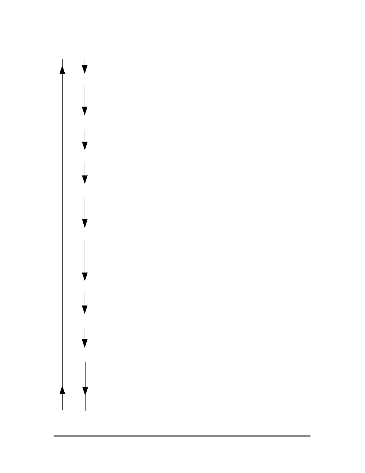
Appendix A Schematic description of settings and data transmission
Initial status: REAL mode
Press PROG and hold down
Pro appears at display and will change to
SCL indication programming mode.
Press PROG
- A- appears at display
Press PROG
current low scale value is displayed and MIN-LED flashs
Adjust value using (
) and ( ) keys
low scale value is changing.
Press PROG
- - - appears, indicating acceptance of new lower scale
value
-E- appears at display
Press PROG
current high scale value is displayed and MAX-LED flashs
Adjust value using (
) and ( ) keys
high scale value changes
Press PROG
- - - appears, indicating acceptance of new upper scale
value
dP. appears and current position of decimal point is
displayed
Page 29

29
Adjust value using ( ) and ( ) keys
decimal point changes
Press PROG
- - - appears, indicating acceptance of new decimal position
InX appears and current index of input signal is displayed
Adjust value using ( ) and ( ) keys
X index figure changes
Press PROG
- - - appears, indicating acceptance of new input signal
OuX appears at display
Adjust value using ( ) and ( ) keys
X index figure changes
Press PROG
- - - appears, indicating acceptance of new output signal
- d - appears at display
Press PROG
set value for damping in seconds appears
Adjust value using ( ) and ( ) keys
set time for damping is changed
Page 30

30
Press PROG
- - - appears, indicating acceptance of the time of damping
dXX appears automatically with the current reference of
damping
Adjust value using ( ) and ( ) keys
reference of damping changes
Press PROG
- - - acceptance of the reference of damping
with - b - appears at display
RS232
Press PROG
set baud rate appears
(values in kBaud).
Adjust value using ( ) and ( ) keys
stored value for the baud rate is
changed.
Press PROG
- - - appears, indicating acceptance of new
baud rate
Hitting RESET immediately terminates the programming mode at any
time. In this instance, the instrument resumes REAL mode.
Only such changes that have been acknowledged by appearance of
"---" will become effective. Otherwise, previously set values remain valid.
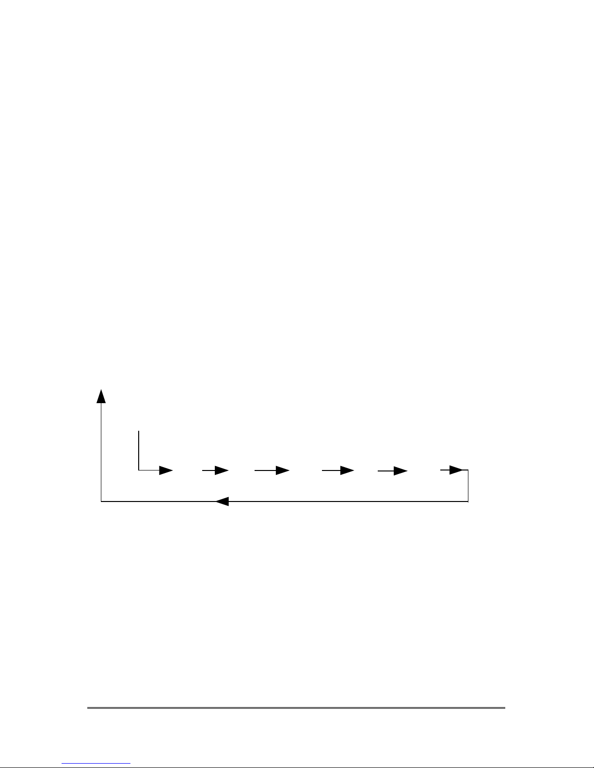
Page 31

31
Short hitting of the PROG key, while the instrument is in REAL mode,
initiates “PRO“ to appear at the display, followed by all current settings
in consecutive order.
Below flow diagram explains appearance of key words and values,
presuming settings of:
Examples:
Scale expansion: 0 ... 6.00 bar
Input signal: 4 ... 20 mA
Signal output: 0 ... 10 V
Damping
: 1.0 s
Reference of damping: Display
Baud rate 9600 baud
Initial status: REAL mode
Press PROG shortly
Pro SCL -A- 0.00 -E- 6.00
d.P In3 Ou1 -d- 01.0 d01
-b- 09.6
Hitting RESET immediately terminates verification mode at any time. In
this instance, the instrument resumes REAL mode.
Page 32
32
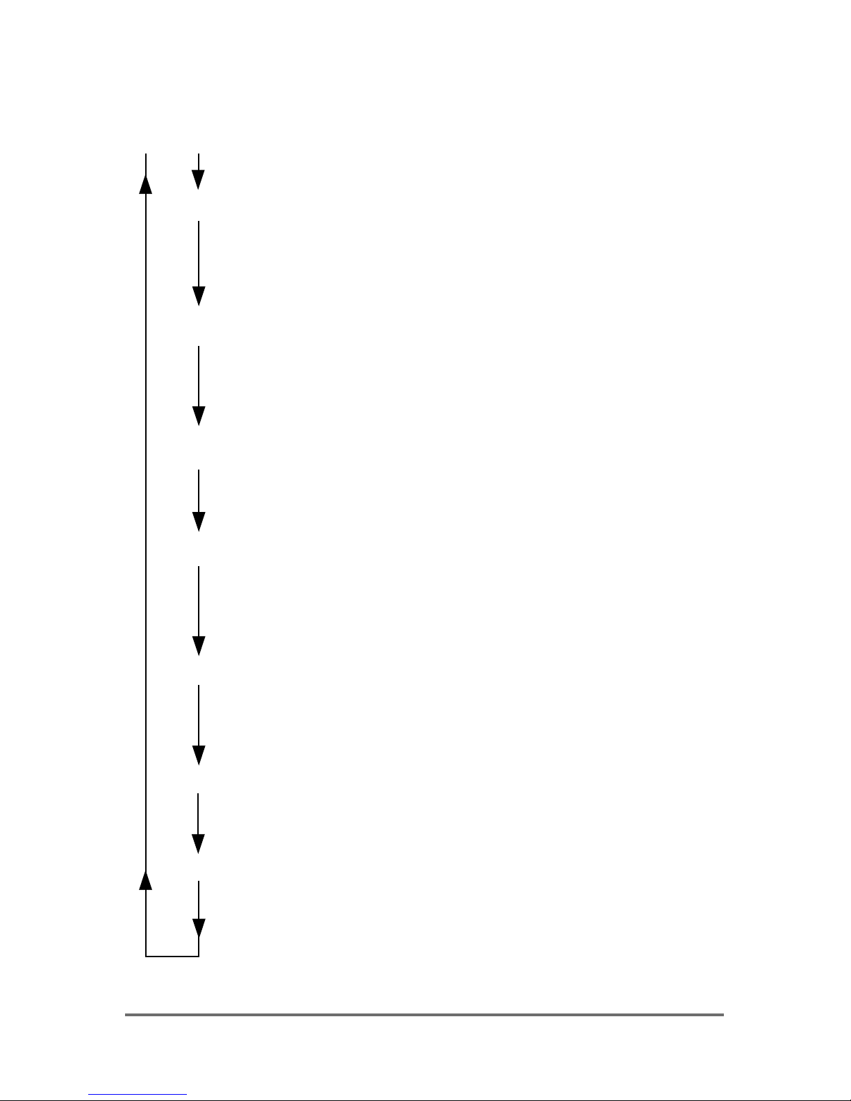
Appendix B Schematic description of alarm settings and verification
Initial status: REAL mode
Press SET 1 and hold down
SP1 appears at display and will change to
SE indicating programming mode
Press SET 1
current Set point make value no. 1 appears and the
- LED of alarm 1 flashs
Adjust value using (
) and ( ) keys
make value changes
Press SET 1
- - - appears, indicating acceptance of new Set point
make value
SA of alarm 1 appears at display
Press SET 1
current Set point break value no. 1 appears and the
- LED of alarm 1 flashs
Adjust value using (
) and ( ) keys
break value changes
Press SET 1
- - - appears, indicating acceptance of new Set point
break value
Page 33
33
Hitting RESET immediately terminates the programming mode at any
time. In this instance, the instrument resumes REAL mode.
Only such changes that have been acknowledged by appearance of
"---" will become effective. Otherwise, previously set values remain
valid.
Set points of alarm 2 are entered in the same manner.
Short hitting of the SET 1 (SET 2, respectively) key, while the instrument
is in REAL mode, initiates verification of the current settings of alarm 1
(2, respectively).
Example:
Set point make (SE): 4.00
Set point break (SA): 3.80
Initial status: REAL mode
Press SET 1 shortly
SP1 SE 4.00 SA 3.80
Hitting RESET immediately terminates verification mode at any time. In
this instance, the instrument resumes REAL mode.
Set points or alarm 2 are verified in the same manner.
Page 34

34
89.5
47.5
95.7
173.5
Appendix C Dimensions
Dimensions in mm
Page 35

35
8.9
42.3
45
+0.6
92
+0.8
Panel cutout in mm
Dimensions in mm
Page 36
36
AB CD EFG HI
d e h
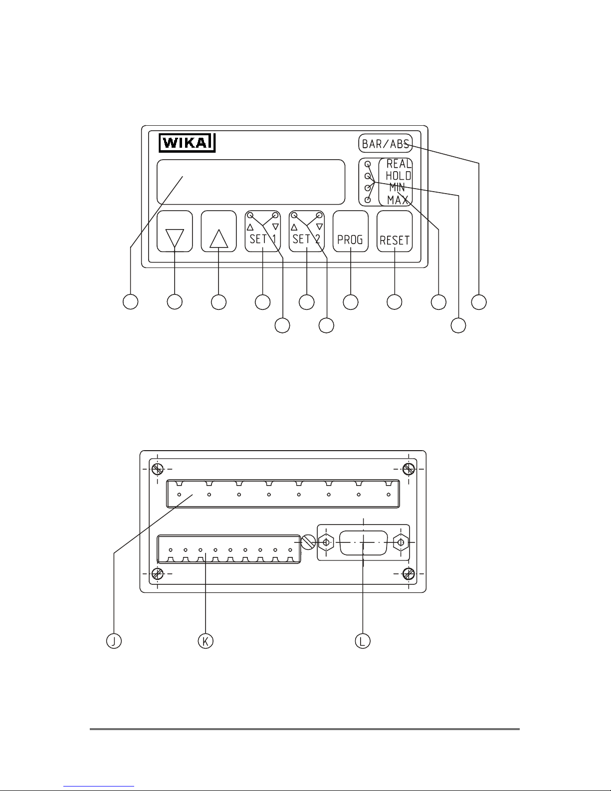
Appendix D Layout of front and back panel
Page 37

37
A LED-display
B Decrease value key
C Increase value key
D Check / set contacts no. 1
d ∆ - LED = MAX value; ∇ - LED = MIN value
E Check / set contacts no. 2
e ∆ - LED = MAX value; ∇ - LED = MIN value
F Select programming mode. Continue with programming
G RESET memories, CANCEL programming
H Select display mode (toggle between LED’s)
h REAL = display true value
HOLD = hold value displayed
MIN = contents of minimum memory displayed
MAX = contents of maximum memory displayed
I Pocket window holding unit label
J Terminal block power supply and contacts output
K Terminal block signal input, signal output and transmitter supply
L Sub-D serial port (optional)
Page 38

38
For your notes
Page 39

39
For your notes
Page 40

40
WIKA Alexander Wiegand GmbH & Co. KG
Alexander-Wiegand-Straße 30
63911 Klingenberg / Germany
Phone (+49) 93 72/132-9986
Fax (+49) 93 72/132-217
E-Mail testequip@wika.de
www.wika.de
1287974 04/2005 GB
 Loading...