

Page 1
Operating instructions
Betriebsanleitung
Mode d'emploi
Manual de instrucciones
Manuale d'uso
Dierential pressure transmitter model A2G-50
Dierenzdrucktransmitter Typ A2G-50
Transmetteur de pression diérentielle type A2G-50
Transmisor de presión diferencial modelo A2G-50
Trasmettitore di pressione dierenziale modello A2G-50
Dierential pressure transmitter model A2G-50
GB
D
F
E
I
Page 2

GB
Operating instructions model A2G-50 Page 3-12
D
Betriebsanleitung Typ A2G-50 Seite 13-22
F
Mode d'emploi type A2G-50 Page 23-32
E
Manual de instrucciones modelo A2G-50 Página 33-42
I
Manuale d'uso modello A2G-50 Pagina 43-52
© 2009 WIKA Alexander Wiegand SE & Co. KG
All rights reserved. / Alle Rechte vorbehalten.
®
WIKA
is a registered trademark in various countries.
®
WIKA
ist eine geschützte Marke in verschiedenen Ländern.
Prior to starting any work, read the operating instructions!
Keep for later use!
Vor Beginn aller Arbeiten Betriebsanleitung lesen!
Zum späteren Gebrauch aufbewahren!
Lire le mode d'emploi avant de commencer toute opération !
A conserver pour une utilisation ultérieure !
¡Leer el manual de instrucciones antes de comenzar cualquier trabajo!
¡Guardar el manual para una eventual consulta!
Prima di iniziare ad utilizzare lo strumento, leggere il manuale d'uso!
Conservare per future consultazioni!
2
WIKA operating instructions air2guide model A2G-50
40202780.02 05/2012 GB/D/F/E/I
Page 3

Contents
Contents
1. General information 4
2. Safety 5
3. Specications 6
Design and function
4.
5. Transport, packaging and storage 9
6. Commissioning, operation 9
7. Zero point adjustment 11
8. Options and accessories 12
9. Maintenance and cleaning 12
10. Disposal 12
8
GB
40202780.02 05/2012 GB/D/F/E/I
WIKA operating instructions air2guide model A2G-50
3
Page 4

1. General information
1. General information
■
The dierential pressure transmitter described in the operating
instructions has been designed and manufactured using state-of-theart technology. All components are subject to stringent quality and
GB
environmental criteria during production. Our management systems
are certied to ISO 9001 and ISO 14001.
■
These operating instructions contain important information on
handling the instrument. Working safely requires that all safety
instructions and work instructions are observed.
■
Observe the relevant local accident prevention regulations and
general safety regulations for the instrument’s range of use.
■
The operating instructions are part of the product and must be kept
in the immediate vicinity of the instrument and readily accessible to
skilled personnel at any time.
■
Skilled personnel must have carefully read and understood the
operating instructions, prior to beginning any work.
■
The manufacturer’s liability is void in the case of any damage caused
by using the product contrary to its intended use, non-compliance
with these operating instructions, assignment of insuciently
qualied skilled personnel or unauthorised modications to the
instrument.
■
The general terms and conditions contained in the sales
documentation shall apply.
■
Subject to technical modications.
■
Further information:
- Internet address: www.wika.de / www.wika.com
www.air2guide.com
- Relevant data sheet: SP 69.03
4
WIKA operating instructions air2guide model A2G-50
40202780.02 05/2012 GB/D/F/E/I
Page 5
1. General information / 2. Safety
Explanation of symbols
WARNING!
... indicates a potentially dangerous situation that can
result in serious injury or death, if not avoided.
Information
… points out useful tips, recommendations and
information for ecient and trouble-free operation.
2. Safety
WARNING!
Before installation, commissioning and operation, ensure
that the appropriate dierential pressure transmitter has
been selected in terms of measuring range, design and
specic measuring conditions.
Non-observance can result in serious injury and/or damage
to the equipment.
Further important safety instructions can be found in the
individual chapters of these operating instructions.
2.1 Intended use
This dierential pressure transmitter is used for:
■
Monitoring the dierential pressure of air and other non-inammable
and non-aggressive gases
■
Monitoring of air lters, blowers in ventilation ducts
■
Control of air and re dampers and for overpressure monitoring in
clean rooms and laboratories
GB
The instrument has been designed and built solely for the intended use
described here, and may only be used accordingly.
40202780.02 05/2012 GB/D/F/E/I
WIKA operating instructions air2guide model A2G-50
5
Page 6
2. Safety / 3. Specications
The manufacturer shall not be liable for claims of any type based on
operation contrary to the intended use.
2.2 Personnel qualication
GB
Skilled personnel
Skilled personnel are understood to be personnel who, based on their
technical training, knowledge of measurement and control technology
and on their experience and knowledge of country-specic regulations,
current standards and directives, are capable of carrying out the work
described and independently recognising potential hazards.
Explanation of symbols
3. Specications
WARNING!
Risk of injury if qualication is insucient!
Improper handling can result in considerable injury and
damage to equipment.
■
The activities described in these operating instructions
may only be carried out by skilled personnel who have
the qualications described below.
CE, Communauté Européenne
Instruments bearing this mark comply with the relevant
European directives.
Process connection
Connecting nozzle (ABS), for hoses with inner diameter 4 or 6 mm
Measuring element
Piezo measuring cell
Case
Plastic (ABS)
6
WIKA operating instructions air2guide model A2G-50
40202780.02 05/2012 GB/D/F/E/I
Page 7
3. Specications
Electrical connection
Cable gland M16, Screw terminals, max. 1.5 mm
Output signal
4 ... 20 mA or 0 … 10 V, 3-wire
Supply voltage
AC 24 V or DC 24 V ±10 %
Power < 1 W (1.5 W with 20 mA) 3-wire models
Long-term stability
0 ... 2,500 Pa ±8 Pa per year
0 ... 7,000 Pa ±24 Pa per year
-250 ... +250 Pa ±3 Pa per year
±1 Pa with automatic zero adjustment (option)
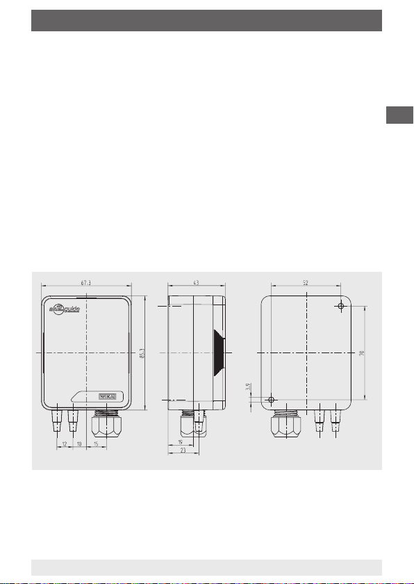
Dimensions in mm
2
GB
Weight
150 g
Ingress protection
IP 54 per EN 60529 / lEC 529
For further specications see WIKA data sheet SP 69.03 and the order
documentation.
40202780.02 05/2012 GB/D/F/E/I
WIKA operating instructions air2guide model A2G-50
7
Page 8

4. Design and function
4. Design and function
4.1 Description
Design
CE conformity:
GB
2004/108/EG Electromagnetic compatibility (EMC)
2002/95/EC RoHS (restriction of the use of certain hazardous
substances in electrical and electronic equipment)
Accuracy
±1.5 %
(with measuring range -250 ... +250 Pa: ±3 %)
Measuring ranges
■
Variant 1: 0 ... 2,500 Pa standard
(-100 ... +100/0 ... 100/250/500/1,000/1,500/2,000 Pa adjustable via
jumper)
■
Variant 2: 0 ... 7,000 Pa standard
(0 ... 1,000/1,500/2,000/2,500/3,000/4,000/5,000 Pa adjustable via
jumper)
■
Variant 3: -250 ... +250 Pa (-25 ... +25/-50 ... +50/
-100... +100/0 ... 25/50/100/250 Pa adjustable via jumper)
Pressure limitation
Maximum pressure: 25 kPa
Burst pressure: 50 kPa
Permissible temperature
Ambient: -20 … +70 °C
Operation: -5 … +50 °C
Permissible ambient humidity
0 … 95 % rH, non-condensing
4.2 Scope of delivery
Cross-check scope of delivery with the delivery note.
8
WIKA operating instructions air2guide model A2G-50
40202780.02 05/2012 GB/D/F/E/I
Page 9

5. Transport, packaging ... / 6. Commissioning, operation
5. Transport, packaging and storage
5.1 Transport
Check the dierential pressure transmitter for any damage that may
have been caused during transportation. Obvious damage must be
reported immediately.
5.2 Packaging
Do not remove packaging until just before mounting.
Keep the packaging as it will provide optimum protection during transport (e.g. change in installation site, sending for repair).
5.3 Storage
Permissible conditions at the place of storage:
Storage temperature: -20 ... +70 °C
Protect the instruments from moisture and dust.
6. Commissioning, operation
Installation and mechanical connection
■
Protect measuring instruments from contamination, high temperature
changes and vibrations
■
In order to avoid any additional heating, the instruments must not be
exposed to direct solar irradiation while in operation.
■
The dierential pressure transmitter must be screw-tted on a
suitable vertical surface. The instrument has to be mounted horizontally using the enclosed mounting screws.
GB
40202780.02 05/2012 GB/D/F/E/I
WIKA operating instructions air2guide model A2G-50
9
Page 10
6. Commissioning, operation
Electrical connection
The instruments are designed to operate with safety extra-low voltage
(SELV). When wiring up the instruments, the technical specications for
those instruments should be followed. As a rule, the transmitter should
GB
be operated in the middle of the measuring range, since deviations can
occur at the range limits. The ambient temperature of the transmitter
electronics should be kept constant.
The dierential pressure transmitters must be operated at a constant
operating voltage (±0.2 V). Current/voltage spikes from switching the
power supply on or o must be prevented by the customer.
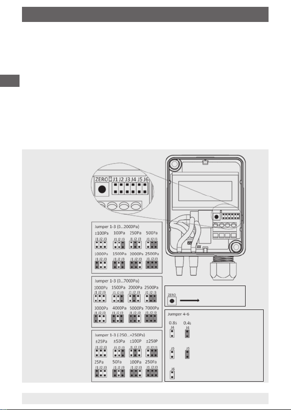
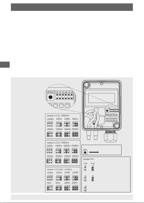
Connection diagram
Zeroing: Press the button
Select unit
Not in use
10
WIKA operating instructions air2guide model A2G-50
LED: Turns ON
Zeroing
Set response time
Note: Measuring unit
can be changed pressing
the ZERO button when
jumper 5 is placed.
Please remove jumper
after setting
40202780.02 05/2012 GB/D/F/E/I
Page 11
6. Commissioning, operation / 7. Zero point adjustment
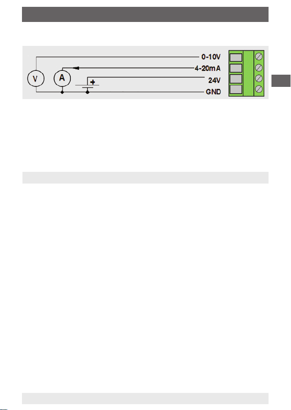
Connection diagram
Output signal 0 ... 10 V
Output signal 4 ... 20 mA
Supply voltage
AC 24 V / DC 24 V
Commissioning
A prerequisite for the commissioning is a proper installation of all
electrical supply, control and measuring lines and of the pressure
connection lines. Before commissioning, the leak tightness of the
pressure connection lines must be checked.
7. Zero point adjustment
7.1 Standard
■
Attention! The power supply must be connected one hour before
calibrating the zero point. Remove both hoses from the pressure
connections ⊕ and ⊖.
■
Press the zero key until the red LED switches on.
■
Wait until the LED switches o again and install the hoses to the
pressure connections again.
■
In normal operation, we recommend that a zero point calibration is
carried out every 12 months.
7.2 Automatic zero adjustment (option)
The automatic zero adjustment makes the instrument maintenancefree. The element adjusts the zero point from time to time and thus
prevents a zero point drift of the piezo-resistive sensor element.
During the zero adjustment the display and output value remains
at the last measured value. The automatic zero adjustment takes
4 seconds and is repeated every 10 minutes.
40202780.02 05/2012 GB/D/F/E/I
WIKA operating instructions air2guide model A2G-50
GB
11
Page 12

8. Options and accessories ... 10. Disposal
8. Options and accessories
Standard accessories
■
2 mounting screws
GB
Options
■
LC display for measured value display
■
Automatic zero adjustment
■
2 duct connectors
■
2 m PVC hose with 4 mm inner diameter
9. Maintenance and cleaning
The dierential pressure transmitter is maintenance-free and oers long
service life provided it is handled and operated properly.
Clean the instruments with a moist cloth (soap water).
Repairs must only be carried out by the manufacturer or appropriately
qualied skilled personnel.
10. Disposal
Incorrect disposal can put the environment at risk.
Dispose of instrument components and packaging materials in an
environmentally compatible way and in accordance with the country-
specic waste disposal regulations.
12
WIKA operating instructions air2guide model A2G-50
40202780.02 05/2012 GB/D/F/E/I
Page 13

Inhalt
Inhalt
1. Allgemeines 14
2. Sicherheit 15
3. Technische Daten 16
Aufbau und Funktion
4.
5. Transport, Verpackung und Lagerung 19
6. Inbetriebnahme, Betrieb 19
7. Nullpunkteinstellung 21
8. Optionen und Zubehör 22
9. Wartung und Reinigung 22
10. Entsorgung 22
18
D
40202780.02 05/2012 GB/D/F/E/I
WIKA Betriebsanleitung air2guide Typ A2G-50
13
Page 14

1. Allgemeines
1. Allgemeines
■
Der in der Betriebsanleitung beschriebene Dierenzdrucktransmitter
wird nach nach dem aktuellen Stand der Technik konstruiert und
gefertigt. Alle Komponenten unterliegen während der Fertigung
strengen Qualitäts- und Umweltkriterien. Unsere Managementsy-
steme sind nach ISO 9001 und ISO 14001 zertiziert.
D
■
Diese Betriebsanleitung gibt wichtige Hinweise zum Umgang mit
dem Gerät. Voraussetzung für sicheres Arbeiten ist die Einhaltung
aller angegebenen Sicherheitshinweise und Handlungsanweisungen.
■
Die für den Einsatzbereich des Gerätes geltenden örtlichen Unfallverhütungsvorschriften und allgemeinen Sicherheitsbestimmungen
einhalten.
■
Die Betriebsanleitung ist Produktbestandteil und muss in unmittelbarer Nähe des Gerätes für das Fachpersonal jederzeit zugänglich
aufbewahrt werden.
■
Das Fachpersonal muss die Betriebsanleitung vor Beginn aller
Arbeiten sorgfältig durchgelesen und verstanden haben.
■
Die Haftung des Herstellers erlischt bei Schäden durch bestimmungswidrige Verwendung, Nichtbeachten dieser Betriebsanleitung,
Einsatz ungenügend qualizierten Fachpersonals sowie eigenmächtiger Veränderung am Gerät.
■
Es gelten die allgemeinen Geschäftsbedingungen in den Verkaufsunterlagen.
■
Technische Änderungen vorbehalten.
■
Weitere Informationen:
- Internet-Adresse: www.wika.de / www.wika.com
www.air2guide.com
- zugehöriges Datenblatt: SP 69.03
14
WIKA Betriebsanleitung air2guide Typ A2G-50
40202780.02 05/2012 GB/D/F/E/I
Page 15
1. Allgemeines / 2. Sicherheit
Symbolerklärung
WARNUNG!
… weist auf eine möglicherweise gefährliche Situation hin,
die zum Tod oder zu schweren Verletzungen führen kann,
wenn sie nicht gemieden wird.
Information
… hebt nützliche Tipps und Empfehlungen sowie Infor-
mationen für einen ezienten und störungsfreien Betrieb
hervor.
2. Sicherheit
WARNUNG!
Vor Montage, Inbetriebnahme und Betrieb sicherstellen,
dass der richtige Dierenzdrucktransmitter hinsichtlich
Messbereich, Ausführung und spezischen Messbedin-
gungen ausgewählt wurde.
Bei Nichtbeachten können schwere Körperverletzungen
und/oder Sachschäden auftreten.
Weitere wichtige Sicherheitshinweise benden sich in den
einzelnen Kapiteln dieser Betriebsanleitung.
2.1 Bestimmungsgemäße Verwendung
Dieser Dierenzdrucktransmitter dient zur:
■
Überwachung des Dierenzdruckes von Luft und anderen nicht
brennbaren und nicht aggressiven Gasen
■
Überwachung von Luftltern, Gebläsen in Lüftungskanälen
■
Regelung von Luft- und Brandschutzklappen und zur Überdrucküberwachung von Reinräumen und Labors
D
Das Gerät ist ausschließlich für den hier beschriebenen bestimmungsgemäßen Verwendungszweck konzipiert und konstruiert und darf nur
dementsprechend verwendet werden.
40202780.02 05/2012 GB/D/F/E/I
WIKA Betriebsanleitung air2guide Typ A2G-50
15
Page 16
2. Sicherheit / 3. Technische Daten
Ansprüche jeglicher Art aufgrund von nicht bestimmungsgemäßer
Verwendung sind ausgeschlossen.
2.2 Personalqualikation
WARNUNG!
D
Fachpersonal
Das Fachpersonal ist aufgrund seiner fachlichen Ausbildung, seiner
Kenntnisse der Mess- und Regelungstechnik und seiner Erfahrungen
sowie Kenntnis der landesspezischen Vorschriften, geltenden Normen
und Richtlinien in der Lage, die beschriebenen Arbeiten auszuführen
und mögliche Gefahren selbstständig zu erkennen.
Symbolerklärung
3. Technische Daten
Verletzungsgefahr bei unzureichender Qualikation!
Unsachgemäßer Umgang kann zu erheblichen Personenund Sachschäden führen.
■
Die in dieser Betriebsanleitung beschriebenen
Tätigkeiten nur durch Fachpersonal nachfolgend
beschriebener Qualikation durchführen lassen.
CE, Communauté Européenne
Geräte mit dieser Kennzeichnung stimmen überein mit den
zutreenden europäischen Richtlinien.
Prozessanschluss
Anschlussstutzen (ABS), für Schläuche mit Innendurchmesser 4 oder
6 mm
Messelement
Piezo-Messzelle
Gehäuse
Kunststo (ABS)
16
WIKA Betriebsanleitung air2guide Typ A2G-50
40202780.02 05/2012 GB/D/F/E/I
Page 17

3. Technische Daten
Elektrischer Anschluss
Kabelverschraubung M16, Schraubklemmen max. 1,5 mm
Ausgangssignal
4 ... 20 mA oder 0 … 10 V, 3-Leiter
Versorgungsspannung
AC 24 V oder DC 24 V ±10 %
Leistung < 1 W (1,5 W mit 20 mA) 3-Leiter-Typen
Langzeitstabilität
0 ... 2.500 Pa ±8 Pa pro Jahr
0 ... 7.000 Pa ±24 Pa pro Jahr
-250 ... +250 Pa ±3 Pa pro Jahr
±1 Pa mit automatischer Nullpunktkorrektur (Option)
Abmessungen in mm
Schutzart
IP 54 nach EN 60529 / lEC 529
2
D
Gewicht
150 g
Weitere technische Daten siehe WIKA-Datenblatt SP 69.03 und
Bestellunterlagen.
40202780.02 05/2012 GB/D/F/E/I
WIKA Betriebsanleitung air2guide Typ A2G-50
17
Page 18

4. Aufbau und Funktion
4. Aufbau und Funktion
4.1 Beschreibung
Ausführung
CE-Konformität:
2004/108/EG Elektromagnetische Verträglichkeit
D
2002/95/EG RoHS (Beschränkung der Verwendung bestimmter
gefährlicher Stoe in Elektro- und Elektronikgeräten)
Genauigkeit
±1,5 %
(bei Messbereich -250 ... +250 Pa: ±3 %)
Messbereiche
■
Variante 1: 0 ... 2.500 Pa Standard
(-100 ... +100/0 ... 100/250/500/1.000/1.500/2.000 Pa über Jumper
einstellbar)
■
Variante 2: 0 ... 7.000 Pa Standard
(0 ... 1.000/1.500/2.000/2.500/3.000/4.000/5.000 Pa über Jumper
einstellbar)
■
Variante 3: -250 ... +250 Pa (-25 ... +25/-50 ... +50/
-100... +100/0 ... 25/50/100/250 Pa über Jumper einstellbar)
Druckbelastbarkeit
Maximaler Druck: 25 kPa
Berstdruck: 50 kPa
Zulässige Temperatur
Umgebung: -20 … +70 °C
Betrieb: -5 … +50 °C
Zulässige Umgebungsfeuchte
0 … 95 % rF, nicht kondensierend
4.2 Lieferumfang
Lieferumfang mit dem Lieferschein abgleichen.
18
WIKA Betriebsanleitung air2guide Typ A2G-50
40202780.02 05/2012 GB/D/F/E/I
Page 19

5. Transport, Verpackung ... / 6. Inbetriebnahme, Betrieb
5. Transport, Verpackung und Lagerung
5.1 Transport
Dierenzdrucktransmitter auf eventuell vorhandene Transportschäden
untersuchen. Oensichtliche Schäden unverzüglich mitteilen.
5.2 Verpackung
Verpackung erst unmittelbar vor der Montage entfernen.
Die Verpackung aufbewahren, denn diese bietet bei einem Transport
einen optimalen Schutz (z. B. wechselnder Einbauort, Reparatursendung).
5.3 Lagerung
Zulässige Bedingungen am Lagerort
Lagertemperatur: -20 … +70 °C
Geräte vor Feuchtigkeit und Staub schützen.
6. Inbetriebnahme, Betrieb
Installation und mechanischer Anschluss
■
Messgeräte vor Verschmutzung und starken Temperaturschwankungen und Vibrationen schützen
■
Um zusätzliche Aufheizungen zu vermeiden, dürfen die Geräte im
Betrieb keiner direkten Sonneneinstrahlung ausgesetzt sein.
■
Der Dierenzdrucktransmitter muss auf einer geeigneten vertikalen
Fläche aufgeschraubt werden. Das Gerät ist waagrecht mit den
beiliegenden Befestigungsschrauben zu befestigen.
D
40202780.02 05/2012 GB/D/F/E/I
WIKA Betriebsanleitung air2guide Typ A2G-50
19
Page 20

6. Inbetriebnahme, Betrieb
Elektrischer Anschluss
Die Geräte sind für den Betrieb an Schutzkleinspannung (SELV)
ausgelegt. Beim elektrischen Anschluss der Geräte gelten die
technischen Daten der Geräte. Der Dierenzdrucktransmitter sollte
in der Regel in der Messbereichsmitte betrieben werden, da an den
Messbereichsendpunkten erhöhte Abweichungen auftreten können.
Die Umgebungstemperatur der Messumformerelektronik sollte konstant
D
gehalten werden.
Die Dierenzdrucktransmitter müssen bei einer konstanten Betriebsspannung (±0,2 V) betrieben werden. Strom-/Spannungsspitzen beim
Ein-/Ausschalten der Versorgungsspannung müssen bauseitig vermieden werden.
Anschlussplan
Nullung: Taste drücken
Einheit wählen
Nicht genutzt
20
WIKA Betriebsanleitung air2guide Typ A2G-50
LED: Geht AN
Nullung
Einstellen der Ansprechzeit
Hinweis: Wenn Jumper
5 gesetzt ist, kann die
Messeinheit durch
Drücken der ZERO-Taste
geändert werden.
Bitte nach dem Einstellen
Jumper entfernen
40202780.02 05/2012 GB/D/F/E/I
Page 21

6. Inbetriebnahme, Betrieb / 7. Nullpunkteinstellung
Anschlussschema
Ausgangssignal 0 ... 10 V
Ausgangssignal 4 ... 20 mA
Hilfsenergie
AC 24 V / DC 24 V
Inbetriebnahme
Voraussetzung für die Inbetriebnahme ist die ordnungsgemäße
Installation aller elektrischen Versorgungs-, Schalt- und Messleitungen
und der Druckanschlussleitungen. Vor Inbetriebnahme ist die Dichtigkeit
der Druckanschlussleitungen zu prüfen.
7. Nullpunkteinstellung
7.1 Standard
■
Achtung! Die Spannungsversorgung muss eine Stunde vor der
Nullpunktkalibrierung angeschlossen sein. Beide Schläuche von
den Druckanschlüssen ⊕ und ⊖ lösen.
■
Null-Taste drücken bis sich die rote LED einschaltet.
■
Warten bis sich die LED wieder ausschaltet und anschließend die
Schläuche wieder an die Druckanschlüsse installieren.
■
Bei normalem Betrieb ist es empfehlenswert, die Nullpunktkalibrierung alle 12 Monate vorzunehmen.
D
7.2 Automatische Nullpunktkorrektur (Option)
Die automatische Nullpunktkorrektur macht das Gerät wartungsfrei.
Das Element korrigiert von Zeit zu Zeit den Nullpunkt und verhindert
somit einen Nullpunktdrift des piezoresistiven Sensorelements.
Während der Nullpunktkorrektur bleibt der Anzeige- und Ausgangswert
beim letzten gemessenen Wert stehen. Die automatische Nullpunktkorrektur dauert 4 Sekunden und wird alle 10 Minuten wiederholt.
40202780.02 05/2012 GB/D/F/E/I
WIKA Betriebsanleitung air2guide Typ A2G-50
21
Page 22

8. Optionen und Zubehör ... 10. Entsorgung
8. Optionen und Zubehör
Standardzubehör
■
2 Befestigungsschrauben
Optionen
■
LC-Display zur Messwertanzeige
D
■
Automatische Nullpunktkorrektur
■
2 Kanalanschlussnippel
■
2 m PVC-Schlauch Innendurchmesser 4 mm
9. Wartung und Reinigung
Der Dierenzdrucktransmitter ist wartungsfrei und zeichnet sich
bei sachgemäßer Behandlung und Bedienung durch eine hohe
Lebensdauer aus.
Reinigen der Geräte mit einem (in Seifenlauge) angefeuchteten Tuch.
Reparaturen sind ausschließlich vom Hersteller oder entsprechend
qualiziertem Fachpersonal durchzuführen.
10. Entsorgung
Durch falsche Entsorgung können Gefahren für die Umwelt entstehen.
Gerätekomponenten und Verpackungsmaterialien entsprechend den
landesspezischen Abfallbehandlungs- und Entsorgungsvorschriften
umweltgerecht entsorgen.
22
WIKA Betriebsanleitung air2guide Typ A2G-50
40202780.02 05/2012 GB/D/F/E/I
Page 23

Sommaire
Sommaire
1. Généralités 24
2. Sécurité 25
3. Spécications 26
Conception et fonction
4.
5. Transport, emballage et stockage 29
6. Mise en service, exploitation 29
7. Réglage du point zéro 31
8. Options et accessoires 32
9. Entretien et nettoyage 32
10. Mise au rebut 32
28
F
40202780.02 05/2012 GB/D/F/E/I
Mode d´emploi WIKA air2guide type A2G-50
23
Page 24

1. Généralités
1. Généralités
■
Le transmetteur de pression diérentielle décrit dans le mode
d'emploi est conçu et fabriqué selon les dernières technologies en
vigueur. Tous les composants sont soumis à des critères de qualité
et d'environnement stricts durant la fabrication. Nos systèmes de
gestion sont certiés selon ISO 9001 et ISO 14001.
■
Ce mode d’emploi donne des indications importantes concernant
F
l’utilisation de l’instrument. Il est possible de travailler en toute
sécurité avec ce produit en respectant toutes les consignes de
sécurité et d’utilisation.
■
Respecter les prescriptions locales de prévention contre les
accidents et les prescriptions générales de sécurité en vigueur pour
le domaine d‘application de l’instrument.
■
Le mode d’emploi fait partie du produit et doit être conservé à
proximité immédiate de l’instrument et être accessible à tout moment
pour le personnel qualié.
■
Le personnel qualié doit, avant de commencer toute opération,
avoir lu soigneusement et compris le mode d’emploi.
■
La responsabilité du fabricant n’est pas engagée en cas de
dommages provoqués par une utilisation non conforme à l’usage
prévu, de non respect de ce mode d’emploi, d’utilisation de
personnel peu qualié de même qu’en cas de modications de
l’instrument eectuées par l’utilisateur.
■
Les conditions générales de vente mentionnées dans les documents
de vente s'appliquent.
■
Sous réserve de modications techniques.
■
Pour obtenir d'autres informations :
- Consulter notre site internet : www.wika.fr
www.air2guide.com
- Fiche technique correspondante : SP 69.03
24
Mode d´emploi WIKA air2guide type A2G-50
40202780.02 05/2012 GB/D/F/E/I
Page 25
1. Généralités / 2. Sécurité
Explication des symboles
AVERTISSEMENT !
… indique une situation présentant des risques susceptibles de provoquer la mort ou des blessures graves si elle
n'est pas évitée.
Information
… met en exergue les conseils et recommandations utiles
de même que les informations permettant d'assurer un
fonctionnement ecace et normal.
2. Sécurité
AVERTISSEMENT !
Avant le montage, la mise en service et le fonctionnement,
s'assurer que le transmetteur de pression diérentielle
a été choisi de façon adéquate, en ce qui concerne la
plage de mesure, la version et les conditions de mesure
spéciques.
Un non-respect de cette consigne peut entraîner des
blessures corporelles graves et/ou des dégâts matériels.
Vous trouverez d'autres consignes de sécurité dans les
sections individuelles du présent mode d'emploi.
2.1 Utilisation conforme à l'usage prévu
Ce transmetteur de pression diérentiel est utilisé pour :
■
La surveillance de la pression diérentielle de l'air et d'autres gaz
non inammables et non agressifs
■
Surveillance de ltres à air, de soueries dans des canaux de
ventilation
■
La surveillance de registres d'air et de clapets coupe-feu et pour
la surveillance de la surpression dans des pièces propres et des
laboratoires
L’instrument est conçu et construit exclusivement pour une utilisation
conforme à l’usage prévu décrit ici et ne doit être utilisé qu’en
conséquence.
40202780.02 05/2012 GB/D/F/E/I
Mode d´emploi WIKA air2guide type A2G-50
F
25
Page 26

2. Sécurité / 3. Spécications
Aucune réclamation ne peut être recevable en cas d'utilisation non
conforme à l'usage prévu.
2.2 Qualication du personnel
AVERTISSEMENT !
Danger de blessure en cas de qualication insufsante!
F
Personnel qualié
Le personnel qualié est, en raison de sa formation spécialisée, de
ses connaissances dans le domaine de la technique de mesure et de
régulation et de ses expériences de même que de sa connaissance des
prescriptions nationales des normes et directives en vigueur, en mesure
d'eectuer les travaux décrits et de reconnaître automatiquement les
dangers potentiels.
Explication des symboles
3. Spécications
Une utilisation non conforme peut entraîner d'importants
dommages corporels et matériels.
■
Les opérations décrites dans ce mode d'emploi ne
doivent être eectuées que par un personnel ayant la
qualication décrite ci-après.
CE, Communauté Européenne
Les instruments avec ce marquage sont conformes aux
directives européennes pertinentes.
Raccord process
Embout de raccordement (ABS), pour tuyaux souples de diamètre
intérieur 4 ou 6 mm
Elément de mesure
Cellule de mesure piézo-électrique
Boîtier
Plastique (ABS)
26
Mode d´emploi WIKA air2guide type A2G-50
40202780.02 05/2012 GB/D/F/E/I
Page 27

3. Spécications
Raccordement électrique
Presse-étoupe M16, Bornes à vis, max. 1,5 mm²
Signal de sortie
4 ... 20 mA ou 0 … 10 V, 3 ls
Tension d'alimentation
24 VAC ou 24 VDC ±10 %
Puissance < 1 W (1,5 W avec 20 mA) types à 3 ls
Stabilité à long terme
0 ... 2.500 Pa ±8 Pa par an
0 ... 7.000 Pa ±24 Pa par an
-250 ... +250 Pa ±3 Pa par an
±1 Pa avec réglage automatique du point zéro (option)
Dimensions en mm
F
Indice de protection
IP 54 selon EN 60529 / lEC 529
Pour de plus amples spécications, voir la che technique WIKA
SP 69.03 et la documentation de commande.
40202780.02 05/2012 GB/D/F/E/I
Mode d´emploi WIKA air2guide type A2G-50
Poids
150 g
27
Page 28

4. Conception et fonction
4. Conception et fonction
4.1 Description
Design
Conformité CE:
2004/108/CE Compatibilité électromagnétique (CEM)
2002/95/CE RoHS (restriction de l'utilisation de certaines substances
dangereuses dans les équipements électriques et électroniques)
F
Précision
±1,5 %
(avec étendue de mesure -250 ... +250 Pa: ±3 %)
Etendues de mesure
■
Exécution 1: 0 ... 2.500 Pa standard
(-100 ... +100/0 ... 100/250/500/1.000/1.500/2.000 Pa ajustable par
cavalier)
■
Exécution 2: 0 ... 7.000 Pa standard
(0 ... 1.000/1.500/2.000/2.500/3.000/4.000/5.000 Pa ajustable par
cavalier)
■
Exécution 3: -250 ... +250 Pa (-25 ... +25/-50 ... +50/
-100... +100/0 ... 25/50/100/250 Pa ajustable par cavalier)
Plages d' utilisation
Pression maximale : 25 kPa
Pression d'éclatement: 50 kPa
Température admissible
Ambiante: -20 … +70 °C
Température de service : -5 … +50 °C
Humidité ambiante admissible
0 ... 95 % d'HR, sans condensation
4.2 Détail de la livraison
Comparer le détail de la livraison avec le bordereau de livraison.
28
Mode d´emploi WIKA air2guide type A2G-50
40202780.02 05/2012 GB/D/F/E/I
Page 29

5. Transport ... / 6. Mise en service, fonctionnement
5. Transport, emballage et stockage
5.1 Transport
Vérier s'il existe des dégâts sur le transmetteur de pression diérentielle liés au transport. Communiquer immédiatement les dégâts
constatés.
5.2 Emballage
N'enlever l'emballage qu'avant le montage.
Conserver l'emballage, celui-ci ore, lors d'un transport, une protection
optimale (par ex. changement de lieu d'utilisation, renvoi pour réparation).
5.3 Stockage
Conditions admissibles sur le lieu de stockage :
Température de stockage : -20 ... +70 °C
Protégez les instruments contre l’humidité et la poussière.
6. Mise en service, exploitation
Installation et branchement mécanique
■
Protégez les instruments de mesure contre la contamination, les
variations de température élevées et les vibrations
■
An d'éviter tout échauement supplémentaire, les instruments ne
doivent pas être exposés directement aux rayons du soleil pendant
le fonctionnement.
F
■
Le transmetteur de pression diérentielle doit être vissé sur
une surface verticale adaptée. L'instrument doit être monté
horizontalement à l'aide des vis de montage fournies.
40202780.02 05/2012 GB/D/F/E/I
Mode d´emploi WIKA air2guide type A2G-50
29
Page 30

6. Mise en service, exploitation
Raccordement électrique
Les instruments sont conçus pour travailler avec une tension extrabasse de sécurité (SELV). Lorsque l'on câble les instruments, il faut
respecter les spécications techniques de ces instruments. En règle
générale, le transmetteur doit être utilisé au milieu de la plage de
mesure, car des déviations peuvent se produire aux limites de l'étendue.
Il faut maintenir constante la température ambiante de l'électronique du
transmetteur.
F
Les transmetteurs de pression diérentielle doivent fonctionner à une
tension constante (±0,2 V). Des pics de courant/tension provenant de
l'allumage et de l'extinction de l'alimentation doivent être évités par le
client.
Schéma de raccordement
Mise à zéro : Appuyer sur le bouton
Sélectionner l’unité
Hors
fonctionnement
30
Mode d´emploi WIKA air2guide type A2G-50
LED: Allumée
Mise à zéro
Congurer le temps de réponse
Note: L’unité de mesure
peut être changée en
appuyant sur le bouton
ZERO quand le cavalier
5 est en place.
Merci d’enlever le
cavalier après réglage
40202780.02 05/2012 GB/D/F/E/I
Page 31

6. Mise en service, exploitation / 7. Réglage du point zéro
Schéma de raccordement
Signal sortie 0 ... 10 V
Signal de sortie 4 ... 20 mA
Tension d'alimentation
CA 24 V / CC 24 V
Mise en service
Une condition préalable à la mise en service est une installation
correcte de toute l'alimentation électrique, des lignes de contrôle et
de mesure et des lignes de raccordement de pression. Avant la mise
en service, il faut contrôler l'étanchéité des lignes de raccordement de
pression.
7. Réglage du point zéro
7.1 Standard
■
Attention ! L'alimentation électrique doit être connectée une heure
avant la calibration du point zéro. Enlevez les deux tuyaux des
raccordements de pression ⊕ et ⊖.
■
Presser la touche zéro jusqu'à ce que la LED rouge s'allume.
■
Attendre jusqu'à ce que la LED s'éteigne et installer à nouveau les
tuyaux sur les raccordements de pression.
■
En fonctionnement normal, nous recommandons de calibrer le point
zéro tous les 12 mois.
7.2 Réglage automatique du point zéro (option)
Le réglage automatique du point zéro fait que l'instrument ne nécessite pas d'entretien. L'élément règle le point zéro de temps en temps et
empêche ainsi une dérive du point zéro de l'élément capteur piézorésistant.
Pendant le réglage du point zéro, la valeur de sortie et d'achage
demeure à la dernière valeur mesurée. Le réglage automatique du
point zéro prend 4 secondes et est répété toutes les 10 minutes.
40202780.02 05/2012 GB/D/F/E/I
Mode d´emploi WIKA air2guide type A2G-50
F
31
Page 32

8. Options et accessoires ... 10. Mise au rebut
8. Options et accessoires
Accessoires standard
■
2 vis de montage
Options
■
Achage LC pour achage de valeur mesurée
■
Réglage automatique du point zéro
F
■
2 connecteurs de conduit
■
2 m de tube PVC de diamètre intérieur de 4 mm
9. Entretien et nettoyage
Le transmetteur de pression diérentielle ne nécessite aucun entretien
et ore une longue durée de vie à condition qu'il soit manipulé et
actionné correctement.
Nettoyez les instruments avec un chion humide (eau savonneuse).
Toute réparation doit être exclusivement conée au fabricant ou au
personnel qualié correspondant.
10. Mise au rebut
Une mise au rebut inadéquate peut entraîner des dangers pour
l'environnement.
Eliminer les composants des instruments et les matériaux d'emballage
conformément aux prescriptions nationales pour le traitement et
l'élimination des déchets et aux lois de protection de l'environnement en
vigueur.
32
Mode d´emploi WIKA air2guide type A2G-50
40202780.02 05/2012 GB/D/F/E/I
Page 33

Contenido
Contenido
1. Información general 14
2. Seguridad 15
3. Datos técnicos 16
Diseño y función
4.
5. Transporte, embalaje y almacenamiento 19
6. Puesta en servicio, funcionamiento 19
7. Ajuste del punto cero 21
8. Opciones y accesorios 22
9. Mantenimiento y limpieza 22
10. Eliminación de residuos 22
40202780.02 05/2012 GB/D/F/E/I
WIKA manual de instrucciones air2guide modelo A2G-50
18
E
33
Page 34

1. Información general
1. Información general
■
El transmisor de presión diferencial descrito en el manual de
instrucciones está construido y fabricado según el estado actual de
la técnica. Todos los componentes están sujetos a rigurosos criterios de calidad y medio ambiente en el proceso de la producción.
Nuestros sistemas de gestión están certicados según ISO 9001 e
ISO 14001.
■
Este manual de instrucciones proporciona indicaciones importantes
acerca del manejo del instrumento. Para que el trabajo con este
E
instrumento sea seguro es imprescindible cumplir con todas las
instrucciones de seguridad y manejo indicadas.
■
Cumplir siempre las normativas sobre la prevención de accidentes
y las normas de seguridad en vigor en el lugar de utilización del
instrumento.
■
El manual de instrucciones es una parte integrante del instrumento
y debe guardarse en la proximidad del mismo para que el personal
especializado pueda consultarlo en cualquier momento.
■
El personal especializado debe haber leído y entendido el manual
de instrucciones antes de comenzar cualquier trabajo.
■
El fabricante queda exento de cualquier responsabilidad en caso de
daños causados por un uso no conforme a la nalidad prevista, la
inobservancia del presente manual de instrucciones, un manejo por
personal insucientemente cualicado así como una modicación no
autorizada del instrumento.
■
Se aplican las condiciones generales de venta incluidas en la
documentación de venta.
■
Modicaciones técnicas reservadas.
■
Para obtener más informaciones consultar:
- Página web: www.wika.es
www.air2guide.com
- Hoja técnica correspondiente: SP 69.03
34
WIKA manual de instrucciones air2guide modelo A2G-50
40202780.02 05/2012 GB/D/F/E/I
Page 35

1. Información general / 2. Seguridad
Explicación de símbolos
¡ADVERTENCIA!
… indica una situación probablemente peligrosa que
pueda causar la muerte o lesiones graves si no se evita.
Información
... destaca consejos y recomendaciones útiles así como
informaciones para una utilización ecaz y libre de fallos.
2. Seguridad
¡ADVERTENCIA!
Antes del montaje, la puesta servicio y el funcionamiento
asegurarse de que se haya seleccionado el transmisor
de presión diferencial adecuado con respecto a rango de
medida, versión y condiciones de medición especícas.
El no respetar las instrucciones puede generar lesiones
graves y/o daños materiales.
Los distintos capítulos de este manual de instrucciones
contienen otras importantes indicaciones de seguridad.
2.1 Uso conforme a lo previsto
Esto transmisor de presión diferencial se utiliza para:
■
La supervisión de la presión diferencial de aire y otros gases no
combustibles y no agresivos
■
Supervisión de ltros de aire, ventiladores en canales de ventilación
■
Regulación de válvulas de ventilación y cortafuegos y para la
supervisión de sobrepresiones en salas limpias y laboratorios
E
El instrumento ha sido diseñado y construido únicamente para la
nalidad aquí descrita y debe utilizarse en conformidad a la misma.
40202780.02 05/2012 GB/D/F/E/I
WIKA manual de instrucciones air2guide modelo A2G-50
35
Page 36

2. Seguridad / 3. Datos técnicos
No se admite ninguna reclamación debido a un manejo no adecuado.
2.2 Cualicación del personal
¡ADVERTENCIA!
¡Riesgo de lesiones debido a una insuciente
cualicación!
Un manejo no adecuado puede causar considerables
daños personales y materiales.
■
Las actividades descritas en este manual de
E
Personal especializado
Debido a su formación profesional, a sus conocimientos de la técnica
de regulación y medición así como a su experiencia y su conocimiento
de las normativas, normas y directivas vigentes en el país de utilización
el personal especializado es capaz de ejecutar los trabajos descritos y
reconocer posibles peligros por sí solo.
Explicación de símbolos
3. Datos técnicos
Conexión a proceso
Racor de conexión (ABS), para mangueras con diámetro interior de 4 o
6 mm
instrucciones deben realizarse únicamente por
personal especializado con la consiguiente
cualicación.
CE, Communauté Européenne
Los instrumentos con este marcaje cumplen las directivas
europeas aplicables.
Elemento de medición
Sensor piezoresistivo
Caja
Plástico (ABS)
36
WIKA manual de instrucciones air2guide modelo A2G-50
40202780.02 05/2012 GB/D/F/E/I
Page 37

3. Datos técnicos
Conexión eléctrica
Racor de cable M16, Bornes max. 1,5 mm
2
Señal de salida
4 ... 20 mA ó 0 … 10 V, 3 hilos
Tensión de alimentación
AC 24 V ó DC 24 V ±10 %
Potencia < 1 W (1,5 W con 20 mA) modelos de 3 hilos
Estabilidad a largo plazo
0 ... 2.500 Pa ±8 Pa por año
0 ... 7.000 Pa ±24 Pa por año
-250 ... +250 Pa ±3 Pa por año
±1 Pa con ajuste automático del punto cero (opción)
Dimensiones en mm
E
Peso
150 g
Tipo de protección
IP 54 según EN 60529 / IEC 529
Para más datos técnicos véase la hoja técnica de WIKA SP 69.03 y la
documentación de pedido.
40202780.02 05/2012 GB/D/F/E/I
WIKA manual de instrucciones air2guide modelo A2G-50
37
Page 38

4. Diseño y función
4. Diseño y función
4.1 Descripción
Modelo
Conformidad CE:
Compatibilidad electromagnética según 2004/108/CE
2002/95/CE RoHS (Restricción al uso de determinadas sustancias
peligrosas en aparatos eléctricos y electrónicos)
Precisión
E
±1,5 %
(con rango de medida -250 ... +250 Pa: ±3 %)
Rangos de medida
■
Variante 1: 0 ... 2.500 Pa estándar
(-100 ... +100/0 ... 100/250/500/1.000/1.500/2.000 Pa ajustable
mediante jumper)
■
Variante 2: 0 ... 7.000 Pa estándar
(0 ... 1.000/1.500/2.000/2.500/3.000/4.000/5.000 Pa ajustable
mediante jumper)
■
Variante 3: -250 ... +250 Pa (-25 ... +25/-50 ... +50/
-100... +100/0 ... 25/50/100/250 Pa ajustable mediante jumper)
Presión admisible
Presión máxima: 25 kPa
Presión de estallido: 50 kPa
Temperatura admisible
Ambiente: -20 … +70 °C
Servicio: -5 … +50 °C
Humedad ambiente admisible
0 ... 95 % rF, sin condensación
4.2 Volumen de suministro
Comparar mediante el albarán si se han entregado todas las piezas.
38
WIKA manual de instrucciones air2guide modelo A2G-50
40202780.02 05/2012 GB/D/F/E/I
Page 39

5. Transporte ... / 6. Puesta en servicio, funcionamiento
5. Transporte, embalaje y almacenamiento
5.1 Transporte
Comprobar si el transmisor de presión diferencial presenta eventuales
daños causados en el transporte. Noticar de inmediato cualquier daño
evidente.
5.2 Embalaje
No quitar el embalaje hasta justo antes del montaje.
Guardar el embalaje ya que es la protección ideal para el transporte
(por ejemplo un cambio del lugar de instalación o un envío del instrumento para posibles reparaciones).
5.3 Almacenamiento
Condiciones admisibles en el lugar de almacenamiento
Temperatura de almacenamiento: -20 ... +70 °C
Proteger los instrumentos de medición de humedad y polvo.
6. Puesta en servicio, funcionamiento
Instalación y conexión mecánica
■
Proteger los dispositivos de medición contra la obturación, las
grandes oscilaciones de temperatura y las vibraciones.
■
No exponer los instrumentos a la radiación solar directa durante el
funcionamiento para evitar un calentamiento adicional.
E
■
El transmisor de presión diferencial debe atornillarse a una super-
cie vertical adecuada. Fijar horizontalmente el aparato con los
tornillos de sujeción suministrados.
40202780.02 05/2012 GB/D/F/E/I
WIKA manual de instrucciones air2guide modelo A2G-50
39
Page 40
6. Puesta en servicio, funcionamiento
Conexión eléctrica
Los aparatos son previstos para la utilización con baja tensión de
protección (SELV). Para la conexión eléctrica de los aparatos se
aplican los datos técnicos de los aparatos. Utilizar el transmisor de
presión diferencial en el centro de la zona de medición porque en
las extremidades pueden manifestarse diferencias elevadas. La
temperatura ambiental de la electrónica de convertidores de medición
debe mantenerse constante.
Los transmisores de presión diferencial deben utilizarse con una
E
tensión de trabajo (±0,2 V) constante. Hay que evitar picos de corriente/
tensión al conectar/desconectar la tensión de alimentación.
Esquema de conexión
Punto cero: pulsar botón
Seleccionar la unidad
No aplicado
40
WIKA manual de instrucciones air2guide modelo A2G-50
LED: ACTIVAR
Cero
Ajustar el tiempo de respuesta
Comentario:
Conguración del Jumper
5 permite el cambio de
la unidad de medida
mediante tecla CERO.
Por favor eliminar
jumper tras ajustar
40202780.02 05/2012 GB/D/F/E/I
Page 41

6. Puesta en servicio ... / 7. Ajuste del punto cero
Esquema de conexión
Señal de salida 0 ... 10 V
Señal de salida 4 ... 20 mA
Alimentación auxiliar
AC 24 V / DC 24 V
Puesta en servicio
Para la puesta en servicio es imprescindible instalar correctamente
todas las líneas de alimentación, conmutación, medición y presión.
Antes de la puesta en servicio hay que comprobar si las líneas de
presión están herméticamente cerradas.
7. Ajuste del punto cero
7.1 Estándar
■
¡Atención! La alimentación de corriente debe estar conectada una
hora antes de calibrar el punto cero. Desconectar los dos tubos de
las tomas de presión ⊕ y ⊖.
■
Pulsar la tecla cero hasta que se ilumine el LED rojo.
■
Esperar que se apague el LED y volver a conectar los tubos a las
tomas de presión.
■
Durante el funcionamiento normal se recomienda calibrar el punto
cero cada 12 meses.
E
7.2 Ajuste automático del punto cero (opción)
El instrumento no necesita mantenimiento gracias a la corrección
automática del punto cero. El elemento corrige el punto cero de vez en
cuando e impide una desviación del punto cero del elemento piezorresistivo de la sonda.
Durante la corrección del punto cero, el valor de indicación y salida se
para en el valor medido por último. La corrección automática del punto
cero dura 4 segundos y se repite cada 10 minutos.
40202780.02 05/2012 GB/D/F/E/I
WIKA manual de instrucciones air2guide modelo A2G-50
41
Page 42

8. Opciones y accesorios ... 10. Eliminación de residuos
8. Opciones y accesorios
Accesorios estándar
■
2 tornillos para la jación
Opciones
■
Pantalla LCD para la indicación del valor de medición
■
Ajuste automático del punto cero
■
2 boquillas de conexión de canal
■
Manguera de PVC de 2 m con un diámetro interior de 4 mm
E
9. Mantenimiento y limpieza
El transmisor de presión diferencial no necesita mantenimiento y se
distingue por su prolongada vida útil si se maneja y opera de forma
apropiada.
Limpiar los instrumentos con un trapo húmedo (mojado en lejía de
jabón).
Todas las reparaciones solamente las debe efectuar el fabricante o
personal especializado e instruido.
10. Eliminación de residuos
Una eliminación incorrecta puede provocar peligros para el medio
ambiente.
Eliminar los componentes de los instrumentos y los materiales de
embalaje conforme a los reglamentos relativos al tratamiento de
residuos y eliminación vigentes en el país de utilización.
42
WIKA manual de instrucciones air2guide modelo A2G-50
40202780.02 05/2012 GB/D/F/E/I
Page 43

Contenuti
Contenuti
1. Informazioni generali 44
2. Norme di sicurezza 45
3. Speciche tecniche 46
Esecuzione e funzioni
4.
5. Trasporto, imballaggio e stoccaggio 49
6. Messa in servizio, funzionamento 49
7. Regolazione dello zero 51
8. Opzioni e accessori 52
9. Manutenzione e pulizia 52
10. Smaltimento 52
48
I
40202780.02 05/2012 GB/D/F/E/I
WIKA manuale d‘uso air2guide, modello A2G-50
43
Page 44

1. Informazioni generali
1. Informazioni generali
■
Il trasmettitore di pressione dierenziale descritto in questo manuale
d‘uso è stato progettato e costruito secondo lo stato dell‘arte della
tecnica. Tutti i componenti sono soggetti a stringenti controlli di
qualità ed ambientali durante la produzione. I nostri sistemi di qualità
sono certicati ISO 9001 e ISO 14001.
■
Questo manuale contiene importanti informazioni sull’uso dello
strumento. Lavorare in sicurezza implica il rispetto delle istruzioni di
sicurezza e di funzionamento.
I
■
Osservare le normative locali in tema di prevenzione incidenti e le
regole di sicurezza generali per il campo d’impiego dello strumento.
■
Il manuale d’uso è parte dello strumento e deve essere conservato
nelle immediate vicinanze dello stesso e facilmente accessibile in
ogni momento al personale qualicato.
■
Il manuale d’uso deve essere letto con attenzione e compreso dal
personale qualicato prima dell’inizio di qualsiasi attività.
■
Il costruttore declina ogni responsabilità per qualsiasi danno causato
da un utilizzo scorretto del prodotto, dal non rispetto delle istruzioni riportate in questo manuale, da un impiego di personale non
adeguatamente qualicato oppure da modiche non autorizzate allo
strumento.
■
Si applicano le nostre condizioni generali di vendita, allegate alla
conferma d’ordine.
■
Soggetto a modiche tecniche.
■
Ulteriori informazioni:
- Indirizzo Internet: www.wika.it
www.air2guide.com
- Scheda tecnica prodotto: SP 69.03
44
WIKA manuale d‘uso air2guide, modello A2G-50
40202780.02 05/2012 GB/D/F/E/I
Page 45

1. Informazioni generali / 2. Norme di sicurezza
Legenda dei simboli
ATTENZIONE!
... indica una situazione di potenziale pericolo che, se non
evitata, può causare ferite gravi o morte.
Informazione
... fornisce suggerimenti utili e raccomandazioni per
l'utilizzo eciente e senza problemi dello strumento.
2. Norme di sicurezza
ATTENZIONE!
Prima dell‘installazione, messa in servizio e funzionamento, assicurarsi che sia stato selezionato il trasmettitore
di pressione dierenziale adatto per quanto riguarda il
campo di misura, l'esecuzione e le condizioni speciche
della misura.
La non osservanza può condurre a ferite gravi o danni alle
apparecchiature.
Altre importanti norme di sicurezza sono riportate nei
singoli capitoli di questo manuale d‘uso.
2.1 Destinazione d’uso
Questo tramsettitore di pressione dierenziale viene usato per:
■
Monitoraggio della pressione dierenziale per aria e gas non inam-
mabili o aggressivi
■
Monitoraggio ltri, ventilatori in condotti di ventilazione
■
Regolazione di serrande aria e serrande tagliafuoco e monitoraggio
della sovrapressione in camere bianche e laboratori
Lo strumento è stato progettato e costruito esclusivamente per la sua
destinazione d’uso e può essere impiegato solo per questa.
40202780.02 05/2012 GB/D/F/E/I
WIKA manuale d‘uso air2guide, modello A2G-50
I
45
Page 46

2. Norme di sicurezza / 3. Speciche tecniche
Il costruttore non è responsabile per reclami di qualsiasi natura in caso
di utilizzo dello strumento al di fuori del suo impiego consentito.
2.2 Qualicazione del personale
ATTENZIONE!
Rischio di infortuni in caso di personale non qualicato!
L‘uso improprio può condurre a gravi infortuni o danni alle
apparecchiature.
■
Le attività riportate in questo manuale d‘uso possono
I
Personale qualicato
Per personale qualicato si intende personale che, sulla base delle
proprie conoscenze tecniche di strumentazione e controllo e delle
normative nazionali e sulla base della propria esperienza, è in grado
di portare a termine il lavoro e riconoscere autonomamente potenziali
pericoli.
Legenda dei simboli
3. Speciche tecniche
essere eettuate solo da personale in possesso delle
qualiche riportate di seguito.
CE, Communauté Européenne
Gli strumenti riportanti questo marchio sono in accordo con
le relative Direttive Europee.
Attacco al processo
Attacchi per tubi (plastica ABS), per tubi con Ø interno da 4 o 6 mm
Elemento di misura
Sensore piezoresistivo
Cassa
Plastica (ABS)
46
WIKA manuale d‘uso air2guide, modello A2G-50
40202780.02 05/2012 GB/D/F/E/I
Page 47

3. Speciche tecniche
Connessione elettrica
Pressacavo M16, morsetti a vite max. 1,5 mm
2
Segnale di uscita
4 ... 20 mA o 0 … 10 V, 3 li
Tensione di alimentazione
AC 24 V o DC 24 V ±10 %
Potenza < 1 W (1,5 W con 20 mA) modelli a 3 li
Stabilità a lungo termine
0 ... 2.500 Pa ±8 Pa per anno
0 ... 7.000 Pa ±24 Pa per anno
-250 ... +250 Pa ±3 Pa per anno
±1 Pa regolazione automatica dello zero (opzione)
Dimensioni in mm
I
Peso
150 g
Grado di protezione
IP 54 conforme a EN 60529 / lEC 529
Per ulteriori informazioni tecniche, fare riferimento alla Scheda tecnica
WIKA SP 69.03 ed ai documenti d'ordine.
40202780.02 05/2012 GB/D/F/E/I
WIKA manuale d‘uso air2guide, modello A2G-50
47
Page 48

4. Esecuzione e funzioni
4. Esecuzione e funzioni
4.1 Descrizione
Esecuzione
Conformità CE:
2004/108/CE compatibilità elettromagnetica (EMC)
2002/95/CE RoHS (restrizioni sull'uso di determinate sostanze pericolose
nella costruzione di vari tipi di apparecchiature elettriche ed elettroniche)
Precisione
±1,5 %
(con campo di misura -250 ... +250 Pa: ±3 %)
I
Campi di misura
■
Variante 1: 0 ... 2.500 Pa standard
(-100 ... +100/0 ... 100/250/500/1.000/1.500/2.000 Pa regolabile
tramite jumper)
■
Variante 2: 0 ... 7.000 Pa standard
(0 ... 1.000/1.500/2.000/2.500/3.000/4.000/5.000 Pa regolabile
tramite jumper)
■
Variante 3: -250 ... +250 Pa (-25 ... +25/-50 ... +50/
-100... +100/0 ... 25/50/100/250 Pa regolabile tramite jumper)
Pressione di lavoro
Massima pressione: 25 kPa
Pressione di scoppio: 50 kPa
Temperature consentite
Ambiente: -20 … +70 °C
Funzionamento: -5 … +50 °C
Umidità ambiente consentita
0 ... 95 % rH, non condensante
4.2 Scopo di fornitura
Controllare lo scopo della fornitura con il documento di consegna /
trasporto.
48
WIKA manuale d‘uso air2guide, modello A2G-50
40202780.02 05/2012 GB/D/F/E/I
Page 49

5. Trasporto, imballaggio ... / 6. Messa in servizio ...
5. Trasporto, imballaggio e stoccaggio
5.1 Trasporto
Controllare che il trasmettitore di pressione dierenziale non sia
stato danneggiato durante il trasporto. Danni evidenti devono essere
segnalati tempestivamente.
5.2 Imballaggio
Rimuovere l‘imballo solo appena prima dell‘installazione.
Conservare l‘imballo per proteggere lo strumento in caso di successivi
trasporti (es. variazione del sito di installazione, invio in riparazione).
5.3 Stoccaggio
Condizioni consentite per lo stoccaggio
Temperatura di stoccaggio: -20 ... +70 °C
Proteggere gli strumenti dall’umidità e dalla polvere.
6. Messa in servizio, funzionamento
Installazione e attacco meccanico
■
Proteggere gli strumenti di misura da contaminazioni, forti escursioni
termiche e vibrazioni.
■
Al ne di evitare ogni riscaldamento aggiuntivo, gli strumenti non
devono essere esposti alla radiazione diretta del sole durante il
funzionamento.
I
■
Il trasmettitore di pressione dierenziale deve essere installato su
una idonea supercie verticale. Lo strumento deve essere montato
orizzontalmente usando le viti di montaggio in dotazione.
40202780.02 05/2012 GB/D/F/E/I
WIKA manuale d‘uso air2guide, modello A2G-50
49
Page 50

6. Messa in servizio, funzionamento
Connessione elettrica
Gli strumenti sono progettati per funzionare con bassissima tensione
di sicurezza (SELV - Safety Extra Low Voltage). Per il collegamento
elettrico si devono osservare le speciche tecniche di questi strumenti.
Di regola, il trasmettitore dovrebbe essere usato al centro del campo
di misura perché ai limiti del campo si possono vericare degli errori.
La temperatura ambiente all'elettronica del trasmettitore deve essere
costante.
Il trasmettitore di pressione dierenziale deve essere utilizzato con una
tensione operativa costante (±0,2 V). Il cliente è tenuto a evitare che si
verichino picchi di corrente/tensione risultanti dall'accensione/dallo
I
spegnimento.
Schema di collegamento
Azzeramento: Premere il tasto
Selezione unità
50
WIKA manuale d‘uso air2guide, modello A2G-50
LED: si ACCENDE
Azzeramento
Impostazione del tempo di risposta
Nota: L’unità di misura
può essere cambiata
premendo il tasto ZERO
dopo aver posizionato il
ponticello 5.
Non in uso
Rimuovere il ponticello
dopo l’impostazione
40202780.02 05/2012 GB/D/F/E/I
Page 51

6. Messa in servizio ... / 7. Regolazione dello zero
Schema di collegamento
Segnale di uscita 0 ... 10 V
Segnale di uscita 4 ... 20 mA
Tensione di alimentazione
AC 24 V / DC 24 V
Messa in funzione
Un prerequisito per la messa in funzione dello strumento è che tutte
le linee di alimentazione, di controllo e di misura e la connessione al
processo siano realizzate correttamente. Prima della messa in funzione,
è necessario controllare la tenuta della connessione al processo.
7. Regolazione dello zero
7.1 Standard
■
Attenzione! L'alimentazione elettrica deve essere collegata un ora
prima di calibrare il punto zero. Scollegare entrambi i tubi dalle
connessioni al processo ⊕ e ⊖.
■
Premere il pulsante punto zero no a quando il LED rosso non si
illumina.
■
Attendere che si spenga il LED e ricollegare i tubi alle connessioni al
processo.
■
Nel funzionamento normale raccomandiamo di calibrare il punto zero
ogni 12 mesi.
I
7.2 Regolazione automatica dello zero (opzione)
Lo strumento non necessita manutenzione grazie alla regolazione
automatica dello zero. Lo strumento eettua frequentemente la
regolazione di zero e previene quindi la deriva di zero del sensore
piezoresistivo.
Durante la regolazione dello zero, i valori di indicazione ed uscita si
fermano all' ultimo valore misurato. La regolazione automatica dello
zero dura 4 secondi e si ripete ogni 10 minuti.
40202780.02 05/2012 GB/D/F/E/I
WIKA manuale d‘uso air2guide, modello A2G-50
51
Page 52

8. Opzioni e accessori ... 10. Smaltimento
8. Opzioni e accessori
Accessori standard
■
2 viti di ssaggio
Opzioni
■
Display LCD per l'indicazione del valore misurato
■
Regolazione automatica dello zero
■
2 adattatori per condotti
■
Tubo essibile in PVC da 2 m con diametro interno 4 mm
9. Manutenzione e pulizia
Il trasmettitore di pressione dierenziale non richiede manutenzione e si
I
distingue per la sua lunga durata se viene utilizzato in modo corretto.
Pulire gli apparecchi con un panno umido (con acqua e sapone).
Le riparazioni devono essere eettuate solo dal costruttore o da
personale adeguatamente qualicato.
10. Smaltimento
Lo smaltimento inappropriato può provocare rischi per l‘ambiente.
Lo smaltimento dei componenti dello strumento e dei materiali di
imballaggio deve essere eettuato in modo compatibile ed in accordo
alle normative nazionali.
WIKA subsidiaries worldwide can be found online at www.wika.com.
WIKA-Niederlassungen weltweit nden Sie online unter www.wika.de.
La liste des liales WIKA dans le monde se trouve sur www.wika.fr.
Sucursales WIKA en todo el mundo puede encontrar en www.wika.es.
Per liali WIKA nel mondo, visitate il nostro sito www.wika.it.
WIKA Alexander Wiegand SE & Co. KG
Alexander-Wiegand-Straße 30
63911 Klingenberg • Germany
Tel (+49) 93 72/132-0
Fax (+49) 93 72/132-406
E-Mail info@wika.de
www.wika.de
52
WIKA manuale d‘uso air2guide, modello A2G-50
40202780.02 05/2012 GB/D/F/E/I
 Loading...