

Page 1
Operating instructions
Betriebsanleitung
Mode d'emploi
Manual de instrucciones
Manuale d'uso
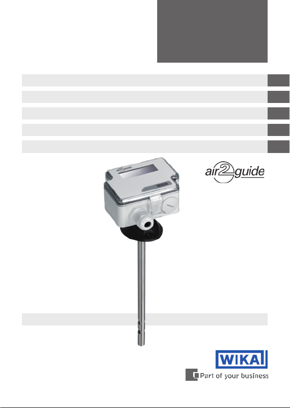
Air velocity transmitter model A2G-20
Luftgeschwindigkeitsmessumformer Typ A2G-20
Transmetteur de vitesse d'air type A2G-20
Transmisor de velocidad del aire modelo A2G-20
Trasmettitore di velocità dell'aria modello A2G-20
Air velocity transmitter model A2G-20
GB
D
F
E
I
Page 2

GB
Operating instructions model A2G-20 Page 3-12
D
Betriebsanleitung Typ A2G-20 Seite 13-22
F
Mode d'emploi type A2G-20 Page 23-32
E
Manual de instrucciones modelo A2G-20 Página 33-42
I
Manuale d'uso modello A2G-20 Pagina 43-52
© 2011 WIKA Alexander Wiegand SE & Co. KG
All rights reserved. / Alle Rechte vorbehalten.
®
WIKA
is a registered trademark in various countries.
®
WIKA
ist eine geschützte Marke in verschiedenen Ländern.
Prior to starting any work, read the operating instructions!
Keep for later use!
Vor Beginn aller Arbeiten Betriebsanleitung lesen!
Zum späteren Gebrauch aufbewahren!
Lire le mode d‘emploi avant de commencer toute opération !
A conserver pour une utilisation ultérieure !
¡Leer el manual de instrucciones antes de comenzar cualquier trabajo!
¡Guardar el manual para una eventual consulta!
Prima di iniziare ad utilizzare lo strumento, leggere il manuale d‘uso!
Conservare per future consultazioni!
2
WIKA operating instructions air2guide model A2G-20
40339556.02 04/2012 GB/D/F/E/I
Page 3

Contents
Contents
1. General information 4
2. Safety 5
3. Specications 6
Design and function
4.
5. Transport, packaging and storage 9
6. Commissioning, operation 9
7. Options and accessories 11
8. Maintenance and cleaning 12
9. Disposal 12
8
GB
40339556.02 04/2012 GB/D/F/E/I
WIKA operating instructions air2guide model A2G-20
3
Page 4

1. General information
1. General information
■
The air velocity transmitter described in the operating instructions
has been designed and manufactured using state-of-the-art
technology. All components are subject to stringent quality and
GB
environmental criteria during production. Our management systems
are certied to ISO 9001 and ISO 14001.
■
These operating instructions contain important information on
handling the instrument. Working safely requires that all safety
instructions and work instructions are observed.
■
Observe the relevant local accident prevention regulations and
general safety regulations for the instrument’s range of use.
■
The operating instructions are part of the product and must be kept
in the immediate vicinity of the instrument and readily accessible to
skilled personnel at any time.
■
Skilled personnel must have carefully read and understood the
operating instructions, prior to beginning any work.
■
The manufacturer’s liability is void in the case of any damage caused
by using the product contrary to its intended use, non-compliance
with these operating instructions, assignment of insuciently
qualied skilled personnel or unauthorised modications to the
instrument.
■
The general terms and conditions contained in the sales
documentation shall apply.
■
Subject to technical modications.
■
Further information:
- Internet address: www.wika.de / www.wika.com
www.air2guide.com
- Relevant data sheet: SP 69.06
4
WIKA operating instructions air2guide model A2G-20
40339556.02 04/2012 GB/D/F/E/I
Page 5
1. General information / 2. Safety
Explanation of symbols
WARNING!
... indicates a potentially dangerous situation which can
result in serious injury or death if not avoided.
Information
… points out useful tips, recommendations and information
for ecient and trouble-free operation.
2. Safety
WARNING!
Before installation, commissioning and operation, ensure
that the appropriate air velocity transmitter has been
selected in terms of measuring range, design and specic
measuring conditions.
Non-observance can result in serious injury and/or damage
to the equipment.
Further important safety instructions can be found in the
individual chapters of these operating instructions.
2.1 Intended use
This air velocity transmitter is used for measuring the air velocity and
temperature in gaseous media of heating, ventilation and air-conditioning systems (e.g. fresh air/exhaust air ducts)
GB
The instrument has been designed and built solely for the intended use
described here and may only be used accordingly.
The manufacturer shall not be liable for claims of any type based on
operation contrary to the intended use.
40339556.02 04/2012 GB/D/F/E/I
WIKA operating instructions air2guide model A2G-20
5
Page 6
2. Safety / 3. Specications
2.2 Personnel qualication
WARNING!
Risk of injury if qualication is insucient!
GB
Improper handling can result in considerable injury and
damage to equipment.
■
The activities described in these operating instructions
may only be carried out by skilled personnel who have
the qualications described below.
Skilled personnel
Skilled personnel are understood to be personnel who, based on their
technical training, knowledge of measurement and control technology
and on their experience and knowledge of country-specic regulations,
current standards and directives, are capable of carrying out the work
described and independently recognising potential hazards.
Explanation of symbols
CE, Communauté Européenne
Instruments bearing this mark comply with the relevant
European directives.
3. Specications
Measuring element
Pt1000 and NTC10k
Case
Plastic (ABS)
Electrical connection
Cable gland M16
Screw terminals, max. 1.5 mm
6
WIKA operating instructions air2guide model A2G-20
2
40339556.02 04/2012 GB/D/F/E/I
Page 7
3. Specications
Output signal
Air velocity:
0 … 10 V (linear to m/s), load min. 1 kΩ or
4 … 20 mA (linear to m/s), load max. 400 Ω
Temperature:
0 … 10 V (linear to °C), load min. 1 kΩ or
4 … 20 mA (linear to °C), load max. 400 Ω
Supply voltage
AC/DC 24 V ±10 %
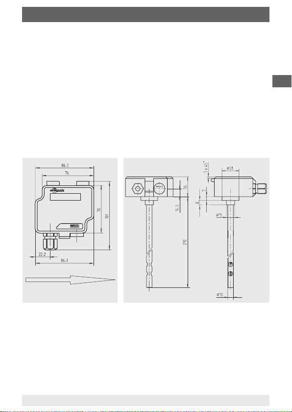
Dimensions in mm
Air ow direction
GB
Ingress protection
IP 54 per EN 60529 / lEC 529
For further specications see WIKA data sheet SP 69.06 and the order
documentation.
40339556.02 04/2012 GB/D/F/E/I
WIKA operating instructions air2guide model A2G-20
7
Page 8

4. Design and function
4. Design and function
Description
Design
EMC directive: 2004/108/EC
GB
RoHS directive: 2002/95/EC
Low voltage directive: 2006/95/EC
WEEE directive: 2002/96/EC
Measuring ranges
Air velocity:
Measuring range 0 … 2 m/s, 0 ... 10 m/s and 0 ... 20 m/s
(settable at the instrument via jumpers)
Temperature: 0 … +50 °C
Accuracy
Air velocity:
Measuring range 0 … 2 m/s: < 0.1 m/s +5 % of measured value
Measuring range 0 ... 10 m/s: < 0.5 m/s +5 % of measured value
Measuring range 0 ... 20 m/s: < 1.0 m/s +5 % of measured value
Temperature:
< 0.5 °C (v > 0.5 m/s)
Permissible temperature
Ambient: 0 ... +50 °C
Operation: 0 … +50 °C, max. 85 % rH
Scope of delivery
Cross-check the scope of delivery with the delivery note.
8
WIKA operating instructions air2guide model A2G-20
40339556.02 04/2012 GB/D/F/E/I
Page 9

5. Transport, packaging ... / 6. Commissioning, operation
5. Transport, packaging and storage
5.1 Transport
Check the air velocity transmitter for any damage that may have been
caused during transportation.
5.2 Packaging
Do not remove packaging until just before mounting.
Keep the packaging as it will provide optimum protection during
transport (e.g. change in installation site, sending for repair).
5.3 Storage
Permissible conditions at the place of storage:
Storage temperature: -20 ... +70 °C
Protect the instruments from moisture and dust.
6. Commissioning, operation
Installation and mechanical connection
The air velocity transmitter is installed in the duct. The cable for the
supply voltage and the cable for the relay connection (optional) have to
be laid separately, if high voltages (no safety extra-low voltage) are to be
switched with the relay. Both cables have their own cable entry.
The relay parameters have to be set before voltage is connected to the
relay connections. This ensures human safety against electric shock.
The instrument is equipped with a lid xing screw. This screw has to
be used, if the voltage connected to the relay connections is no safety
extra-low voltage.
GB
40339556.02 04/2012 GB/D/F/E/I
WIKA operating instructions air2guide model A2G-20
9
Page 10
6. Commissioning, operation
Electrical connection
The instruments are designed to operate with safety extra-low voltage
(SELV). When wiring up the instruments, the technical specications
for those instruments should be followed. In the case of a sensor with
GB
transmitter, as a rule, the transmitter should be operated in the middle
of the measuring range, since deviations can occur at the range limits.
The ambient temperature of the transmitter electronics should be kept
constant.
The transmitters must be operated at a constant operating voltage
(±0.2 V). Current/voltage spikes from switching the power supply on or
o must be prevented by the customer.
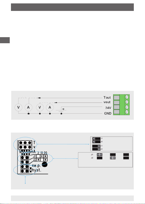
Connection diagram
Output 0 ... 10 V / 4 ... 20 mA (temperature)
Output 0 ... 10 V / 4 ... 20 mA (air velocity)
Supply voltage
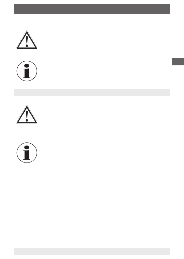
Connection diagram
Temperature 4 ... 20 mA air
Jumper for the setting of the outputs (mA/V)
Both outputs can be set independently
Jumper measuring range
Jumper:
Measuring range: 2 m/s 10 m/s 20 m/s
velocity 4 ... 20 mA
Temperature 0 ... 10 V air velocity
0 ... 10 V
see commissioning of the option with relay
10
WIKA operating instructions air2guide model A2G-20
40339556.02 04/2012 GB/D/F/E/I
Page 11

6. Commissioning, operation / 7. Options and accessories
Commissioning
A prerequisite for the commissioning is a proper installation of all
electrical supply, control and measuring lines and of the pressure
connection lines. Before commissioning, the leak tightness of the
pressure connection lines must be checked.
The air velocity transmitter is supplied with a special protection cap
protecting the sensitive sensor element against damage during
transport. Before commissioning, this protection cap absolutely must
be removed!
Commissioning of the option with relay
Jumper and pushbutton for the setting of the relay parameters:
Set the jumper "switching point" (sw.p.) and then push the button to set
the desired switching point. The set value (m/s) is shown in the display.
Set the jumper "hysteresis" (hyst.) and then push the button to set the
desired hysteresis of the relay switching point. The set value (m/s) is
shown in the display.
7. Options and accessories
Standard accessories
■
Mounting ange
GB
Options
■
LC display for measured value display
■
LC display for measured value display and relay (potential-free,
change-over contact, max. AC 250 V, 6 A, DC 30 V, 6 A, adjustable
switch point and hysteresis)
40339556.02 04/2012 GB/D/F/E/I
WIKA operating instructions air2guide model A2G-20
11
Page 12

8. Maintenance and cleaning / 9. Disposal
8. Maintenance and cleaning
The air velocity transmitter is maintenance-free and oers long service
life provided it is handled and operated properly.
GB
Clean the instruments with a moist cloth (soap water).
Repairs must only be carried out by the manufacturer or appropriately
qualied skilled personnel.
9. Disposal
Incorrect disposal can put the environment at risk.
Dispose of instrument components and packaging materials in an
environmentally compatible way and in accordance with the country-
specic waste disposal regulations.
12
WIKA operating instructions air2guide model A2G-20
40339556.02 04/2012 GB/D/F/E/I
Page 13

Inhalt
Inhalt
1. Allgemeines 14
2. Sicherheit 15
3. Technische Daten 16
Aufbau und Funktion
4.
5. Transport, Verpackung und Lagerung 19
6. Inbetriebnahme, Betrieb 19
7. Optionen und Zubehör 21
8. Wartung und Reinigung 22
9. Entsorgung 22
18
D
40339556.02 04/2012 GB/D/F/E/I
WIKA Betriebsanleitung air2guide Typ A2G-20
13
Page 14

1. Allgemeines
1. Allgemeines
■
Der in der Betriebsanleitung beschriebene Luftgeschwindigkeitsmessumformer wird nach den neuesten Erkenntnissen konstruiert
und gefertigt. Alle Komponenten unterliegen während der Fertigung
strengen Qualitäts- und Umweltkriterien. Unsere Managementsy-
steme sind nach ISO 9001 und ISO 14001 zertiziert.
D
■
Diese Betriebsanleitung gibt wichtige Hinweise zum Umgang mit
dem Gerät. Voraussetzung für sicheres Arbeiten ist die Einhaltung
aller angegebenen Sicherheitshinweise und Handlungsanweisungen.
■
Die für den Einsatzbereich des Gerätes geltenden örtlichen Unfallverhütungsvorschriften und allgemeinen Sicherheitsbestimmungen
einhalten.
■
Die Betriebsanleitung ist Produktbestandteil und muss in unmittelbarer Nähe des Gerätes für das Fachpersonal jederzeit zugänglich
aufbewahrt werden.
■
Das Fachpersonal muss die Betriebsanleitung vor Beginn aller
Arbeiten sorgfältig durchgelesen und verstanden haben.
■
Die Haftung des Herstellers erlischt bei Schäden durch bestimmungswidrige Verwendung, Nichtbeachten dieser Betriebsanleitung,
Einsatz ungenügend qualizierten Fachpersonals sowie eigenmächtiger Veränderung am Gerät.
■
Es gelten die allgemeinen Geschäftsbedingungen in den Verkaufsunterlagen.
■
Technische Änderungen vorbehalten.
■
Weitere Informationen:
- Internet-Adresse: www.wika.de / www.wika.com
www.air2guide.com
- zugehöriges Datenblatt: SP 69.06
14
WIKA Betriebsanleitung air2guide Typ A2G-20
40339556.02 04/2012 GB/D/F/E/I
Page 15
1. Allgemeines / 2. Sicherheit
Symbolerklärung
WARNUNG!
… weist auf eine möglicherweise gefährliche Situation hin,
die zum Tod oder zu schweren Verletzungen führen kann,
wenn sie nicht gemieden wird.
Information
… hebt nützliche Tipps und Empfehlungen sowie Infor-
mationen für einen ezienten und störungsfreien Betrieb
hervor.
2. Sicherheit
WARNUNG!
Vor Montage, Inbetriebnahme und Betrieb sicherstellen,
dass der richtige Luftgeschwindigkeitsmessumformer
hinsichtlich Messbereich, Ausführung und spezischen
Messbedingungen ausgewählt wurde.
Bei Nichtbeachten können schwere Körperverletzungen
und/oder Sachschäden auftreten.
Weitere wichtige Sicherheitshinweise benden sich in den
einzelnen Kapiteln dieser Betriebsanleitung.
2.1 Bestimmungsgemäße Verwendung
Dieser Luftgeschwindigkeitsmessumformer dient zur Messung der
Luftgeschwindigkeit und Temperatur in gasförmigen Medien von
Heizungsanlagen, Lüftungsanlagen und Klimaanlagen (z. B. in Zuluft-/
Abluftkanälen).
D
Das Gerät ist ausschließlich für den hier beschriebenen bestimmungsgemäßen Verwendungszweck konzipiert und konstruiert und darf nur
dementsprechend verwendet werden.
Ansprüche jeglicher Art aufgrund von nicht bestimmungsgemäßer
Verwendung sind ausgeschlossen.
40339556.02 04/2012 GB/D/F/E/I
WIKA Betriebsanleitung air2guide Typ A2G-20
15
Page 16
2. Sicherheit / 3. Technische Daten
2.2 Personalqualikation
WARNUNG!
Verletzungsgefahr bei unzureichender Qualikation!
Unsachgemäßer Umgang kann zu erheblichen Personenund Sachschäden führen.
■
D
Die in dieser Betriebsanleitung beschriebenen Tätigkeiten nur durch Fachpersonal nachfolgend beschrie-
bener Qualikation durchführen lassen.
Fachpersonal
Das Fachpersonal ist aufgrund seiner fachlichen Ausbildung, seiner
Kenntnisse der Mess- und Regelungstechnik und seiner Erfahrungen
sowie Kenntnis der landesspezischen Vorschriften, geltenden Normen
und Richtlinien in der Lage, die beschriebenen Arbeiten auszuführen
und mögliche Gefahren selbstständig zu erkennen.
Symbolerklärung
CE, Communauté Européenne
Geräte mit dieser Kennzeichnung stimmen überein mit den
zutreenden europäischen Richtlinien.
3. Technische Daten
Messelement
Pt1000 und NTC10k
Gehäuse
Kunststo (ABS)
Elektrischer Anschluss
Kabelverschraubung M16
Schraubklemmen max. 1,5 mm
16
2
40339556.02 04/2012 GB/D/F/E/I
WIKA Betriebsanleitung air2guide Typ A2G-20
Page 17

3. Technische Daten
Ausgangssignal
Luftgeschwindigkeit:
0 … 10 V (linear zu m/s), Last min. 1 kΩ oder
4 … 20 mA (linear zu m/s), Last max. 400 Ω
Temperatur:
0 … 10 V (linear zu °C), Last min. 1 kΩ oder
4 … 20 mA (linear zu °C), Last max. 400 Ω
Versorgungsspannung
AC/DC 24 V ±10 %
Abmessungen in mm
Richtung des Luftstromes
D
Schutzart
IP 54 nach EN 60529 / lEC 529
Weitere technische Daten siehe WIKA-Datenblatt SP 69.06 und
Bestellunterlagen.
40339556.02 04/2012 GB/D/F/E/I
WIKA Betriebsanleitung air2guide Typ A2G-20
17
Page 18

4. Aufbau und Funktion
4. Aufbau und Funktion
Beschreibung
Ausführung
EMV-Richtlinie: 2004/108/EC
RoHS-Richtlinie: 2002/95/EC
D
Niederspannungsrichtlinie: 2006/95/EC
WEEE-Richtlinie: 2002/96/EC
Messbereiche
Luftgeschwindigkeit:
Messbereich 0 … 2 m/s, 0 ... 10 m/s und 0 ... 20 m/s
(über Jumper am Gerät einstellbar)
Temperatur: 0 … +50 °C
Genauigkeit
Luftgeschwindigkeit:
Messbereich 0 … 2 m/s: < 0,1 m/s +5 % vom Messwert
Messbereich 0 ... 10 m/s: < 0,5 m/s +5 % vom Messwert
Messbereich 0 ... 20 m/s: < 1,0 m/s +5 % vom Messwert
Temperatur:
< 0,5 °C (v > 0,5 m/s)
Zulässige Temperatur
Umgebung: 0 ... +50 °C
Betrieb: 0 … +50 °C, max. 85 % rF
Lieferumfang
Lieferumfang mit dem Lieferschein abgleichen.
18
WIKA Betriebsanleitung air2guide Typ A2G-20
40339556.02 04/2012 GB/D/F/E/I
Page 19

5. Transport, Verpackung ... / 6. Inbetriebnahme, Betrieb
5. Transport, Verpackung und Lagerung
5.1 Transport
Luftgeschwindigkeitsmessumformer auf eventuell vorhandene Trans-
portschäden untersuchen. Oensichtliche Schäden unverzüglich
mitteilen.
5.2 Verpackung
Verpackung erst unmittelbar vor der Montage entfernen.
Die Verpackung aufbewahren, denn diese bietet bei einem Transport
einen optimalen Schutz (z. B. wechselnder Einbauort, Reparatursendung).
5.3 Lagerung
Zulässige Bedingungen am Lagerort
Lagertemperatur: -20 … +70 °C
Geräte vor Feuchtigkeit und Staub schützen.
6. Inbetriebnahme, Betrieb
Installation und mechanischer Anschluss
Der Luftgeschwindigkeitsmessumformer wird im Kanal eingebaut. Das
Kabel für die Versorgungsspannung und das Kabel für den Relaisanschluss (optional) müssen separat verlegt werden, wenn hohe
Spannungen (keine Schutzkleinspannung) mit dem Relais geschaltet
werden sollen. Für beide Kabel steht eine eigene Kabeleinführung zur
Verfügung.
Die Einstellung der Relaisparameter muss vor dem Anschluss der
Spannung an den Relaisanschlüssen durchgeführt werden. Dies
gewährleistet die Vermeidung eines elektrischen Schlags.
Das Gerät ist mit einer Deckelbefestigungsschraube ausgestattet. Diese
Schraube muss verwendet werden, wenn die an den Relaisanschlüssen
angeschlossene Spannung keine Schutzkleinspannung ist.
D
40339556.02 04/2012 GB/D/F/E/I
WIKA Betriebsanleitung air2guide Typ A2G-20
19
Page 20

6. Inbetriebnahme, Betrieb
Elektrischer Anschluss
Die Geräte sind für den Betrieb an Schutzkleinspannung (SELV)
ausgelegt. Beim elektrischen Anschluss der Geräte gelten die
technischen Daten der Geräte. Bei Fühlern mit Messumformer sollte
dieser in der Regel in der Messbereichsmitte betrieben werden, da
an den Messbereichsendpunkten erhöhte Abweichungen auftreten
D
können. Die Umgebungstemperatur der Messumformerelektronik sollte
konstant gehalten werden.
Die Messumformer müssen bei einer konstanten Betriebsspannung
(±0,2 V) betrieben werden. Strom-/Spannungsspitzen beim Ein-/
Ausschalten der Versorgungsspannung müssen bauseitig vermieden
werden.
Anschlussschema
Ausgang 0 ... 10 V / 4 ... 20 mA (Temperatur)
Ausgang 0 ... 10 V / 4 ... 20 mA (Luftgeschwindigkeit)
Versorgungsspannung
Anschlussplan
Temperatur 4 ... 20 mA
Jumper für die Einstellung der Ausgänge (mA/V)
Beide Ausgänge können unabhängig eingestellt werden
Jumper Messbereich
Jumper:
Messbereich: 2 m/s 10 m/s 20 m/s
Luftgeschwindigkeit 4 ... 20 mA
Temperatur 0 ... 10 V
Luftgeschwindigkeit 0 ... 10 V
siehe Inbetriebnahme der Option mit Relais
20
WIKA Betriebsanleitung air2guide Typ A2G-20
40339556.02 04/2012 GB/D/F/E/I
Page 21

6. Inbetriebnahme, Betrieb / 7. Optionen und Zubehör
Inbetriebnahme
Voraussetzung für die Inbetriebnahme ist die ordnungsgemäße
Installation aller elektrischen Versorgungs-, Schalt- und Messleitungen
und der Druckanschlussleitungen. Vor Inbetriebnahme ist die Dichtigkeit
der Druckanschlussleitungen zu prüfen.
Der Luftgeschwindigkeitsmessumformer wird mit einer speziellen
Schutzkappe ausgeliefert, welche das empndliche Sensorelement
vor Transportschäden schützt. Vor der Inbetriebnahme ist diese
Schutzkappe unbedingt zu entfernen!
Inbetriebnahme der Option mit Relais
Jumper und Taster für die Einstellung der Relaisparameter:
Jumper "Schaltschwelle" (sw.p.) stecken und anschließend die
Taste drücken um die gewünschte Schaltschwelle einzustellen. Der
eingestellte Wert (m/s) wird im Display angezeigt.
Jumper "Hysterese" (hyst.) stecken und anschließend die Taste drücken
um die gewünschte Hysterese der Relaisschaltschwelle einzustellen.
Der eingestellte Wert (m/s) wird im Display angezeigt.
7. Optionen und Zubehör
Standardzubehör
■
Montageansch
D
Optionen
■
LC-Display zur Messwertanzeige
■
LC-Display zur Messwertanzeige und Relais (potentialfrei, Wechsler,
max. AC 250 V, 6 A, DC 30 V, 6 A, einstellbare Schaltschwelle und
Hysterese)
40339556.02 04/2012 GB/D/F/E/I
WIKA Betriebsanleitung air2guide Typ A2G-20
21
Page 22

8. Wartung und Reinigung / 9. Entsorgung
8. Wartung und Reinigung
Der Luftgeschwindigkeitsmessumformer ist wartungsfrei und zeichnet
sich bei sachgemäßer Behandlung und Bedienung durch eine hohe
Lebensdauer aus.
Reinigen der Geräte mit einem (in Seifenlauge) angefeuchteten Tuch.
D
Reparaturen sind ausschließlich vom Hersteller oder entsprechend
qualiziertem Fachpersonal durchzuführen.
9. Entsorgung
Durch falsche Entsorgung können Gefahren für die Umwelt entstehen.
Gerätekomponenten und Verpackungsmaterialien entsprechend den
landesspezischen Abfallbehandlungs- und Entsorgungsvorschriften
umweltgerecht entsorgen.
22
WIKA Betriebsanleitung air2guide Typ A2G-20
40339556.02 04/2012 GB/D/F/E/I
Page 23

Sommaire
Sommaire
1. Généralités 24
2. Sécurité 25
3. Particularités 26
Conception et fonction
4.
5. Transport, emballage et stockage 29
6. Mise en service, exploitation 29
7. Options et accessoires 31
8. Entretien et nettoyage 32
9. Mise au rebut 32
F
28
40339556.02 04/2012 GB/D/F/E/I
Mode d´emploi WIKA air2guide type A2G-20
23
Page 24

1. Généralités
1. Généralités
■
Le transmetteur de vitesse d'air décrit dans le mode d'emploi est
conçu et fabriqué selon les dernières technologies en vigueur.
Tous les composants sont soumis à des critères de qualité et
d'environnement stricts durant la fabrication. Nos systèmes de
gestion sont certiés selon ISO 9001 et ISO 14001.
■
Ce mode d’emploi donne des indications importantes concernant
F
l’utilisation de l’instrument. Il est possible de travailler en toute
sécurité avec ce produit en respectant toutes les consignes de
sécurité et d’utilisation.
■
Respecter les prescriptions locales de prévention contre les
accidents et les prescriptions générales de sécurité en vigueur pour
le domaine d‘application de l’instrument.
■
Le mode d’emploi fait partie du produit et doit être conservé à
proximité immédiate de l’instrument et être accessible à tout moment
pour le personnel qualié.
■
Le personnel qualié doit, avant de commencer toute opération,
avoir lu soigneusement et compris le mode d’emploi.
■
La responsabilité du fabricant n’est pas engagée en cas de
dommages provoqués par une utilisation non conforme à l’usage
prévu, de non respect de ce mode d’emploi, d’utilisation de
personnel peu qualié de même qu’en cas de modications de
l’instrument eectuées par l’utilisateur.
■
Les conditions générales de vente mentionnées dans les documents
de vente s'appliquent.
■
Sous réserve de modications techniques.
■
Pour obtenir d'autres informations :
- Consulter notre site internet : www.wika.fr
www.air2guide.com
- Fiche technique correspondante : SP 69.06
24
Mode d´emploi WIKA air2guide type A2G-20
40339556.02 04/2012 GB/D/F/E/I
Page 25

1. Généralités / 2. Sécurité
Explication des symboles
AVERTISSEMENT !
… indique une situation présentant des risques
susceptibles de provoquer la mort ou des blessures graves
si elle n'est pas évitée.
Information
… met en exergue les conseils et recommandations utiles
de même que les informations permettant d'assurer un
fonctionnement ecace et normal.
2. Sécurité
AVERTISSEMENT !
Avant le montage, la mise en service et le fonctionnement, s'assurer que le transmetteur de vitesse d'air a été
choisi de façon adéquate, en ce qui concerne la plage de
mesure, la version et les conditions de mesure spéciques.
Un non-respect de cette consigne peut entraîner des
blessures corporelles graves et/ou des dégâts matériels.
Vous trouverez d'autres consignes de sécurité dans les
sections individuelles du présent mode d'emploi.
2.1 Utilisation conforme à l'usage prévu
Ce transmetteur de vitesse d'air est utilisé pour mesurer la vitesse de
l'air et la température en milieu gazeux de chauage, de ventilation et
d'air conditionné (par ex. conduits d’air frais, conduits d'évacuation d'air)
F
L’instrument est conçu et construit exclusivement pour une utilisation
conforme à l'usage prévu décrit ici et ne doit être utilisé qu'en
conséquence.
Aucune réclamation ne peut être recevable en cas d'utilisation non
conforme à l'usage prévu.
40339556.02 04/2012 GB/D/F/E/I
Mode d´emploi WIKA air2guide type A2G-20
25
Page 26

2. Sécurité / 3. Particularités
2.2 Qualication du personnel
AVERTISSEMENT !
Danger de blessure en cas de qualication insufsante !
Une utilisation non conforme peut entraîner d'importants
dommages corporels et matériels.
■
Les opérations décrites dans ce mode d'emploi ne
F
doivent être eectuées que par un personnel ayant la
qualication décrite ci-après.
Personnel qualié
Le personnel qualié est, en raison de sa formation spécialisée, de
ses connaissances dans le domaine de la technique de mesure et de
régulation et de ses expériences de même que de sa connaissance des
prescriptions nationales des normes et directives en vigueur, en mesure
d'eectuer les travaux décrits et de reconnaître automatiquement les
dangers potentiels.
Explication des symboles
CE, Communauté Européenne
Les appareils avec ce marquage sont conformes aux directives européennes pertinentes.
3. Particularités
Élément de mesure
Pt1000 et NTC10k
Boîtier
Plastique (ABS)
Branchement électrique
Presse-étoupe M16
Bornes à vis, max. 1,5 mm²
26
Mode d´emploi WIKA air2guide type A2G-20
40339556.02 04/2012 GB/D/F/E/I
Page 27

3. Particularités
Signal de sortie
Vitesse de l'air :
0 … 10 V (linéaire à m/s), charge min. 1 kΩ ou
4 … 20 mA (linéaire à m/s), charge max. 400 Ω
Température :
0 … 10 V (linéaire à °C), charge min. 1 kΩ ou
4 … 20 mA (linéaire à °C), charge max. 400 Ω
Tension d'alimentation
AC/DC 24 V ±10 %
Dimensions en mm
Direction d’écoulement de l’air
Indice de protection
IP 54 selon EN 60529 / lEC 529
Pour de plus amples spécications, voir la che technique WIKA
SP 69.06 et la documentation de commande.
40339556.02 04/2012 GB/D/F/E/I
Mode d´emploi WIKA air2guide type A2G-20
F
27
Page 28

4. Conception et fonction
4. Conception et fonction
Description
Design
Directive CEM: 2004/108/EC
Directive RoHS: 2002/95/EC
Directive basse tension: 2006/95/EC
Directive WEEE: 2002/96/EC
F
Étendues de mesure
Vitesse de l'air:
étendue de mesure 0 … 2 m/s, 0 ... 10 m/s et 0 ... 20 m/s
(réglable sur l'instrument par des cavaliers)
Température: 0 … +50 °C
Précision
Vitesse de l'air:
étendue de mesure 0 … 2 m/s: < 0,1 m/s +5 % de la valeur mesurée
Étendue de mesure 0 … 10 m/s: < 0,5 m/s +5 % de la valeur mesurée
Étendue de mesure 0 … 20 m/s: < 1,0 m/s +5 % de la valeur mesurée
Température:
< 0.5 °C (v > 0.5 m/s)
Température admissible
Ambiante: 0 ... +50 °C
Fonctionnement: 0 … +50 °C, max. 85 % rH
Détail de la livraison
Comparer le détail de la livraison avec le bordereau de livraison.
28
Mode d´emploi WIKA air2guide type A2G-20
40339556.02 04/2012 GB/D/F/E/I
Page 29

5. Transport, emballage ... / 6. Mise en service, exploitation
5. Transport, emballage et stockage
5.1 Transport
Vérier s'il existe des dégâts sur le transmetteur de vitesse d'air liés au
transport.
5.2 Emballage
N'enlever l'emballage qu'avant le montage.
Conserver l'emballage, celui-ci ore, lors d'un transport, une protection
optimale (par ex. changement de lieu d'utilisation, renvoi pour
réparation).
5.3 Stockage
Conditions admissibles sur le lieu de stockage :
Température de stockage : -20 ... +70 °C
Protégez les instruments contre l’humidité et la poussière.
6. Mise en service, exploitation
Installation et raccordement mécanique
Le transmetteur de vitesse d'air est installé dans le conduit. Le câble de
tension d'alimentation et le câble pour la connexion du relais (en option)
doivent être posés séparément, si des tensions hautes (pas de TBTS,
Très Basse Tension de Sécurité) doivent être commutées avec le relais.
Les deux câbles ont leur propre entrée.
Les paramètres du relai doivent être dénis avant que la tension soit
connectée aux branchements du relai. Ceci assure une sécurité pour
l'homme contre une électrocution.
Cet instrument est équipé d'une vis de xation couvercle. Il faut utiliser
cette vis si la tension branchée aux connections du relai n'est pas du
type TBTS.
F
40339556.02 04/2012 GB/D/F/E/I
Mode d´emploi WIKA air2guide type A2G-20
29
Page 30

6. Mise en service, exploitation
Branchement électrique
Les instruments sont conçus pour fonctionner avec une très basse
tension de sécurité (TBTS). Lorsque vous branchez les instruments, il
faut respecter les spécications techniques de ces instruments. Dans le
cas d'un capteur avec transmetteur, en règle générale, le transmetteur
doit être actionné au milieu de l'étendue de mesure, car des déviations
peuvent se produire à la limite de l'étendue. La température ambiante
F
du système électronique du transmetteur doit être maintenue à une
valeur constante.
Les transmetteurs doivent fonctionner à une tension constante (±0.2 V).
Des pics de courant/tension provenant de l'allumage et de l'extinction
de l'alimentation doivent être évités par le client.
Schéma de raccordement
Sortie 0 ... 10 V / 4 ... 20 mA (température)
Sortie 0 ... 10 V / 4 ... 20 mA (vitesse de l'air)
Tension d'alimentation
Schéma de raccordement
Température 4 ... 20 mA vitesse
Cavalier pour le réglage des sorties (mA/V)
Les deux sorties peuvent être réglées indépendamment
Étendue de mesure
du cavalier
Cavalier:
Étendue de mesure: 2 m/s 10 m/s 20 m/s
d'air 4 ... 20 mA
Température 0 ... 10 V vitesse
d'air 0 ... 10 V
voir Mise en service de l'option avec relais
30
Mode d´emploi WIKA air2guide type A2G-20
40339556.02 04/2012 GB/D/F/E/I
Page 31

6. Mise en service, exploitation / 7. Options et accessoires
Mise en service
Une condition préalable à la mise en service est une installation
correcte de toute l'alimentation électrique, des lignes de contrôle et
de mesure et des lignes de raccordement de pression. Avant la mise
en service, il faut contrôler l'étanchéité des lignes de raccordement de
pression.
Le transmetteur de vitesse d'air est équipé d'un capot de protection
spécial qui protège le capteur élément sensible contre tout dommage
pendant le transport. Avant la mise en service, il faut absolument
enlever ce capot de protection !
Mise en service de l'option avec relais
Cavalier et bouton poussoir pour le réglage des paramètres de relais:
Réglez le point de commutation "du cavalier" (sw.p., switching point) et
pressez ensuite la touche pour régler le point de commutation désiré.
La valeur réglée (m/s) est indiquée sur l'écran.
Réglez l'hystérésis "du cavalier" (hyst.) et pressez ensuite la touche
pour régler l'hystérésis désirée du point de commutation du relais.
La valeur réglée (m/s) est indiquée sur l'écran.
7. Options et accessoires
Accessoires standard
■
Bride de montage
Options
■
Achage LC pour achage de valeur mesurée
■
Achage LC pour achage de la valeur mesurée et du relais (sans
potentiel, contact de commutation, max. 250 VAC, 6 A, 30 VDC, 6 A,
point de commutation ajustable et hystérésis)
40339556.02 04/2012 GB/D/F/E/I
Mode d´emploi WIKA air2guide type A2G-20
F
31
Page 32

8. Entretien et nettoyage / 9. Mise au rebut
8. Entretien et nettoyage
Le transmetteur de vitesse d'air ne nécessite aucun entretien et ore
une longue durée de vie à condition qu'il soit manipulé et actionné
correctement.
Nettoyez les instruments avec un chion humide (eau savonneuse).
F
Toute réparation doit être exclusivement conée au fabricant ou au
personnel qualié correspondant.
9. Mise au rebut
Une mise au rebut inadéquate peut entraîner des dangers pour
l'environnement.
Éliminer les composants des appareils et les matériaux d'emballage
conformément aux prescriptions nationales pour le traitement et
l'élimination des déchets et aux lois de protection de l'environnement en
vigueur.
32
Mode d´emploi WIKA air2guide type A2G-20
40339556.02 04/2012 GB/D/F/E/I
Page 33

Contenido
Contenido
1. Información general 34
2. Seguridad 35
3. Datos técnicos 36
Diseño y función
4.
5. Transporte, embalaje y almacenamiento 39
6. Puesta en servicio, funcionamiento 39
7. Opciones y accesorios 41
8. Mantenimiento y limpieza 42
9. Eliminación de residuos 42
38
E
40339556.02 04/2012 GB/D/F/E/I
WIKA manual de instrucciones air2guide modelo A2G-20
33
Page 34

1. Información general
1. Información general
■
El transmisor de velocidad del aire descrito en el manual de
instrucciones está construido y fabricado según los conocimientos
actuales. Todos los componentes están sujetos a criterios rígidos de
calidad y medio ambiente en el proceso de la producción. Nuestros
sistemas de gestión están certicados según ISO 9001 e ISO 14001.
■
Este manual de instrucciones proporciona indicaciones importantes
acerca del manejo del instrumento. Para que el trabajo con este
instrumento sea seguro es imprescindible cumplir con todas las
E
instrucciones de seguridad y manejo indicadas.
■
Cumplir siempre las normativas sobre la prevención de accidentes
y las normas de seguridad en vigor en el lugar de utilización del
instrumento.
■
El manual de instrucciones es una parte integrante del instrumento
y debe guardarse en la proximidad del mismo para que el personal
especializado pueda consultarlo en cualquier momento.
■
El personal especializado debe haber leído y entendido el manual
de instrucciones antes de comenzar cualquier trabajo.
■
El fabricante queda exento de cualquier responsabilidad en caso de
daños causados por un uso no conforme a la nalidad prevista, la
inobservancia del presente manual de instrucciones, un manejo por
personal insucientemente cualicado así como una modicación no
autorizada del instrumento.
■
Se aplican las condiciones generales de venta incluidas en la
documentación de venta.
■
Modicaciones técnicas reservadas.
■
Para obtener más informaciones consultar:
- Página web: www.wika.es
www.air2guide.com
- Hoja técnica correspondiente: SP 69.06
34
WIKA manual de instrucciones air2guide modelo A2G-20
40339556.02 04/2012 GB/D/F/E/I
Page 35

1. Información general / 2. Seguridad
Explicación de símbolos
¡ADVERTENCIA!
… indica una situación probablemente peligrosa que
pueda causar la muerte o lesiones graves si no se evita.
Información
... marca consejos y recomendaciones útiles así como
informaciones para una utilización ecaz y libre de fallos.
2. Seguridad
¡ADVERTENCIA!
Antes del montaje, la puesta servicio y el funcionamiento
asegurarse de que se haya seleccionado el transmisor
de velocidad del aire adecuado con respecto a rango de
medida, versión y condiciones de medición especícas.
El no respetar las instrucciones puede generar lesiones
graves y/o daños materiales.
Los distintos capítulos de este manual de instrucciones
contienen otras importantes indicaciones de seguridad.
2.1 Uso conforme a lo previsto
Este transmisor de velocidad del aire se utiliza para medir la velocidad
del aire y la temperatura en gases de calefacciones, sistemas de ventilación y sistemas de aire acondicionado (p. ej. en conductos de aire
fresco/de escape).
E
El instrumento ha sido diseñado y construido únicamente para la
nalidad aquí descrita y debe utilizarse en conformidad a la misma.
No se admite ninguna reclamación debido a un manejo inadecuado.
40339556.02 04/2012 GB/D/F/E/I
WIKA manual de instrucciones air2guide modelo A2G-20
35
Page 36

2. Seguridad / 3. Datos técnicos
2.2 Cualicación del personal
¡ADVERTENCIA!
¡Riesgo de lesiones debido a una insuciente
cualicación!
Un manejo no adecuado puede causar considerables
daños personales y materiales.
■
Las actividades descritas en este manual de
instrucciones deben realizarse únicamente por
E
personal especializado con la consiguiente
cualicación.
Personal especializado
Debido a su formación profesional, a sus conocimientos de la técnica
de regulación y medición así como a su experiencia y su conocimiento
de las normativas, normas y directivas vigentes en el país de utilización
el personal especializado es capaz de ejecutar los trabajos descritos y
reconocer posibles peligros por sí solo.
Explicación de símbolos
CE, Communauté Européenne
Los instrumentos con este marcaje cumplen las
directivas europeas aplicables.
3. Datos técnicos
Elemento de medición
Pt1000 y NTC10k
Caja
Plástico (ABS)
Conexión eléctrica
Racor de cable M16
Bornes max. 1,5 mm
36
2
WIKA manual de instrucciones air2guide modelo A2G-20
40339556.02 04/2012 GB/D/F/E/I
Page 37

3. Datos técnicos
Señal de salida
Velocidad del aire:
0 … 10 V (lineal a m/s), carga mín. 1 kΩ ó
4 … 20 mA (lineal a m/s), carga máx. 400 Ω
Temperatura:
0 … 10 V (lineal a °C), carga mín. 1 kΩ ó
4 … 20 mA (lineal a °C), carga máx. 400 Ω
Tensión de alimentación
AC/DC 24 V ±10 %
Dimensiones en mm
Dirección de la corriente de aire
E
Tipo de protección
IP 66 según EN 60529 / IEC 529
Para más datos técnicos véase la hoja técnica de WIKA SP 69.06 y la
documentación de pedido.
40339556.02 04/2012 GB/D/F/E/I
WIKA manual de instrucciones air2guide modelo A2G-20
37
Page 38

4. Diseño y función
4. Diseño y función
Descripción
Versión
Directiva de EMC: 2004/108/CE
Directiva RoHS: 2002/95/CE
Directiva de baja tensión: 2006/95/CE
Directiva WEEE: 2002/96/CE
Rangos de medida
E
Velocidad del aire:
Rangos de medida 0 … 2 m/s, 0 ... 10 m/s y 0 ... 20 m/s
(ajustables en el instrumento mediante jumper)
Temperatura: 0 ... +50 °C
Precisión
Velocidad del aire:
Rango de medida 0 … 2 m/s: < 0,1 m/s +5 % del valor de medición
Rango de medida: 0 ... 10 m/s: < 0,5 m/s +5 % del valor de medición
Rango de medida: 0 ... 20 m/s: < 1,0 m/s +5 % del valor de medición
Temperatura:
< 0,5 °C (v > 0,5 m/s)
Temperatura admisible
Ambiente: 0 ... +50 °C
Operación: 0 … +50 °C, máx. 85 % rF
Volumen de suministro
Comprobar mediante el albarán si se ha entregado la totalidad de las
piezas.
38
WIKA manual de instrucciones air2guide modelo A2G-20
40339556.02 04/2012 GB/D/F/E/I
Page 39

5. Transporte, embalaje ... / 6. Puesta en servicio ...
5. Transporte, embalaje y almacenamiento
5.1 Transporte
Comprobar si el transmisor de velocidad del aire presenta eventuales
daños causados en el transporte. Noticar daños obvios de forma
inmediata.
5.2 Embalaje
No quitar el embalaje hasta justo antes del montaje.
Guardar el embalaje ya que es la protección ideal para el transporte
(por ejemplo un cambio del lugar de instalación o un envío del instrumento para posibles reparaciones).
5.3 Almacenamiento
Condiciones admisibles en el lugar de almacenamiento
Temperatura de almacenamiento: -20 ... +70 °C
Proteger los instrumentos de medición de humedad y polvo.
6. Puesta en servicio, funcionamiento
Instalación y conexión mecánica
El transmisor de velocidad del aire se instala en el canal. El cable para
la tensión de alimentación y el cable para la conexión del relé (opcional)
deben colocarse por separado si se reglan tensiones altas (no la baja
tensión de protección) con el relé. Para los dos cables se dispone de un
prensaestopas cada uno.
Hay que ajustar los parámetros del relé antes de conectar la tensión a
las conexiones del mismo para evitar descargas eléctricas.
El instrumento está equipado con un tornillo de jación de la tapa.
Utilizar este tornillo si la tensión conectada a las conexiones del relé no
es una baja tensión de protección.
E
40339556.02 04/2012 GB/D/F/E/I
WIKA manual de instrucciones air2guide modelo A2G-20
39
Page 40

6. Puesta en servicio, funcionamiento
Conexión eléctrica
Los aparatos son previstos para la utilización con baja tensión de
protección (SELV). Para la conexión eléctrica de los aparatos se
aplican los datos técnicos de los aparatos. Si se utilizan sensores
con convertidores de medición, utilizarlos en el centro de la zona de
medición porque en las extremidades pueden manifestarse diferencias
elevadas. La temperatura ambiental de la electrónica de convertidores
de medición debe mantenerse constante.
Los convertidores de medición deben utilizarse con una tensión de
E
trabajo (±0,2 V) constante. Hay que evitar picos de corriente/tensión al
conectar/desconectar la tensión de alimentación.
Esquema de conexión
Salida 0 ... 10 V / 4 ... 20 mA (temperatura)
Salida 0 ... 10 V / 4 ... 20 mA (velocidad del aire)
Tensión de alimentación
Esquema de conexión
Temperatura 4 ... 20 mA
Jumper para ajustar las salidas (mA/V)
Las dos salidas pueden ajustarse por separado.
Jumper del rango de
medida
Jumper:
Rango de medida: 2 m/s 10 m/s 20 m/s
velocidad del aire 4 ... 20 mA
Temperatura 0 ... 10 V velocidad
del aire 0 ... 10 V
Véase Puesta en servicio de la opción con relé
40
WIKA manual de instrucciones air2guide modelo A2G-20
40339556.02 04/2012 GB/D/F/E/I
Page 41

6. Puesta en servicio, funcionamiento / 7. Opciones y ...
Puesta en servicio
Para la puesta en servicio es imprescindible instalar correctamente
todas las líneas de alimentación, conmutación, medición y presión.
Antes de la puesta en servicio hay que comprobar si las líneas de
presión están herméticamente cerradas.
El transmisor de velocidad del aire se entrega con una tapa protectora
especial que protege el sensor sensible de daños de transporte.
¡Quitar la tapa protectora antes de la puesta en servicio!
Puesta en servicio de la opción con relé
Jumper y botón para ajustar los parámetros del relé:
Conectar el jumper "Umbral de conmutación" (sw.p.) y pulsar el botón
para ajustar el umbral de conmutación deseado. En la pantalla se
visualiza el valor ajustado (m/s).
Conectar el jumper "Histéresis" (hyst.) y pulsar el botón para ajustar
la histéresis deseada del umbral del relé. En la pantalla se visualiza
el valor ajustado (m/s).
7. Opciones y accesorios
Accesorios estándar
■
Brida
E
Opciones
■
Pantalla LCD para la indicación del valor de medición
■
Pantalla LCD para la indicación del valor de medición y relé (libre
de potencial, inversor, máx. AC 250 V, 6 A, DC 30 V, 6 A, umbral de
conmutación e histéresis ajustables)
40339556.02 04/2012 GB/D/F/E/I
WIKA manual de instrucciones air2guide modelo A2G-20
41
Page 42

8. Mantenimiento y limpieza / 9. Eliminación de residuos
8. Mantenimiento y limpieza
El transmisor de velocidad del aire no necesita mantenimiento y se
distingue por su prolongada vida útil si se maneja y opera de forma
apropiada.
Limpiar los instrumentos con un trapo húmedo (mojado en lejía de
jabón).
Todas las reparaciones solamente las debe efectuar el fabricante o
E
personal especializado e instruido.
9. Eliminación de residuos
Una eliminación incorrecta puede provocar peligros para el medio
ambiente.
Eliminar los componentes de los instrumentos y los materiales de
embalaje conforme a los reglamentos relativos al tratamiento de
residuos y eliminación vigentes en el país de utilización.
42
WIKA manual de instrucciones air2guide modelo A2G-20
40339556.02 04/2012 GB/D/F/E/I
Page 43

Contenuti
Contenuti
1. Informazioni generali 44
2. Norme di sicurezza 45
3. Speciche tecniche 46
Esecuzione e funzioni
4.
5. Trasporto, imballaggio e stoccaggio 49
6. Messa in servizio, funzionamento 49
7. Opzioni e accessori 51
8. Manutenzione e pulizia 52
9. Smaltimento 52
48
I
40339556.02 04/2012 GB/D/F/E/I
WIKA manuale d‘uso air2guide, modello A2G-20
43
Page 44

1. Informazioni generali
1. Informazioni generali
■
Il trasmettitore di velocità dell'aria descritto in questo manuale d‘uso
è stato progettato e costruito secondo lo stato dell‘arte della tecnica.
Tutti i componenti sono soggetti a stringenti controlli di qualità ed
ambientali durante la produzione. I nostri sistemi di qualità sono
certicati ISO 9001 e ISO 14001.
■
Questo manuale contiene importanti informazioni sull’uso dello
strumento. Lavorare in sicurezza implica il rispetto delle istruzioni di
sicurezza e di funzionamento.
I
■
Osservare le normative locali in tema di prevenzione incidenti e le
regole di sicurezza generali per il campo d’impiego dello strumento.
■
Il manuale d’uso è parte dello strumento e deve essere conservato
nelle immediate vicinanze dello stesso e facilmente accessibile in
ogni momento al personale qualicato.
■
Il manuale d’uso deve essere letto con attenzione e compreso dal
personale qualicato prima dell’inizio di qualsiasi attività.
■
Il costruttore declina ogni responsabilità per qualsiasi danno causato
da un utilizzo scorretto del prodotto, dal non rispetto delle istruzioni
riportate in questo manuale, da un impiego di personale non
adeguatamente qualicato oppure da modiche non autorizzate allo
strumento.
■
Si applicano le nostre condizioni generali di vendita, allegate alla
conferma d’ordine.
■
Soggetto a modiche tecniche.
■
Ulteriori informazioni:
- Indirizzo Internet: www.wika.it
www.air2guide.com
- Scheda tecnica prodotto: SP 69.06
44
WIKA manuale d‘uso air2guide, modello A2G-20
40339556.02 04/2012 GB/D/F/E/I
Page 45

1. Informazioni generali / 2. Norme di sicurezza
Legenda dei simboli
ATTENZIONE!
... indica una situazione di potenziale pericolo che, se non
evitata, può causare ferite gravi o morte.
Informazione
... fornisce suggerimenti utili e raccomandazioni per
l'utilizzo eciente e senza problemi dello strumento.
2. Norme di sicurezza
ATTENZIONE!
Prima dell‘installazione, messa in servizio e funzionamento, assicurarsi che sia stato selezionato il trasmettitore
di velocità dell'aria adatto per quanto riguarda il campo
di misura, l'esecuzione e le condizioni speciche della
misura.
La non osservanza può condurre a ferite gravi o danni alle
apparecchiature.
Altre importanti norme di sicurezza sono riportate nei
singoli capitoli di questo manuale d‘uso.
2.1 Destinazione d’uso
Questo trasmettitore di velocità dell'aria è impiegato per la misura della
velocità dell'aria e della temperatura in uidi gassosi negli impianti di
riscaldamento, ventilazione e condizionamento dell'aria (es. condotti
aria fresca/di scarico)
I
Lo strumento è stato progettato e costruito esclusivamente per la sua
destinazione d’uso e può essere impiegato solo per questa.
Il costruttore non è responsabile per reclami di qualsiasi natura in caso
di utilizzo dello strumento al di fuori del suo impiego consentito.
40339556.02 04/2012 GB/D/F/E/I
WIKA manuale d‘uso air2guide, modello A2G-20
45
Page 46

2. Norme di sicurezza / 3. Speciche tecniche
2.2 Qualicazione del personale
ATTENZIONE!
Rischio di infortuni in caso di personale non qualicato!
L‘uso improprio può condurre a gravi infortuni o danni alle
apparecchiature.
■
Le attività riportate in questo manuale d‘uso possono
essere eettuate solo da personale in possesso delle
qualiche riportate di seguito.
Personale qualicato
I
Per personale qualicato si intende personale che, sulla base delle
proprie conoscenze tecniche di strumentazione e controllo e delle
normative nazionali e sulla base della propria esperienza, è in grado
di portare a termine il lavoro e riconoscere autonomamente potenziali
pericoli.
Legenda dei simboli
CE, Communauté Européenne
Gli strumenti riportanti questo marchio sono in accordo con
le relative Direttive Europee.
3. Speciche tecniche
Elemento di misura
Pt1000 e NTC10k
Custodia
Plastica (ABS)
Connessione elettrica
Pressacavo lettato M16
Morsetti a vite max. 1,5 mm
46
2
40339556.02 04/2012 GB/D/F/E/I
WIKA manuale d‘uso air2guide, modello A2G-20
Page 47

3. Speciche tecniche
Segnale di uscita
Velocità dell'aria:
0 … 10 V (lineare m/s), carico min. 1 kΩ opp.
4 … 20 mA (lineare m/s), carico max. 400 Ω
Temperatura:
0 … 10 V (lineare °C), carico min. 1 kΩ opp
4 … 20 mA (lineare °C), carico max. 400 Ω
Tensione di alimentazione
AC/DC 24 V ±10 %
Dimensioni in mm
Direzione usso aria
Grado di protezione
IP 54 conforme a EN 60529 / lEC 529
Per ulteriori informazioni tecniche, fare riferimento alla Scheda Tecnica
WIKA SP 69.06 ed ai documenti d'ordine.
40339556.02 04/2012 GB/D/F/E/I
WIKA manuale d‘uso air2guide, modello A2G-20
I
47
Page 48

4. Esecuzione e funzioni
4. Esecuzione e funzioni
Descrizione
Esecuzione
Direttiva EMC: 2004/108/EC
Direttiva RoHS: 2002/95/EC
Direttiva bassa tensione: 2006/95/EC
Direttiva WEEE: 2002/96/EC
Campi di misura
Velocità dell'aria:
I
Campi di misura 0 ... 2 m/s, 0 ... 10 m/s e 0 ... 20 m/s
(impostabili sullo strumento tramite ponticelli)
Temperatura: 0 … +50 °C
Precisione
Velocità dell'aria:
Campo di misura 0 … 2 m/s: < 0.1 m/s +5 % del valore misurato
Campo di misura 0 ... 10 m/s: < 0.5 m/s +5 % del valore misurato
Campo di misura 0 ... 20 m/s: < 1.0 m/s +5 % del valore misurato
Temperatura:
< 0.5 °C (v > 0.5 m/s)
Temperature consentite
Ambiente: 0 ... +50 °C
Funzionamento: 0 … +50 °C, max. 85 % rH
Scopo di fornitura
Controllare lo scopo della fornitura con il documento di consegna /
trasporto.
48
WIKA manuale d‘uso air2guide, modello A2G-20
40339556.02 04/2012 GB/D/F/E/I
Page 49

5. Trasporto, imballaggio ... / 6. Messa in servizio ...
5. Trasporto, imballaggio e stoccaggio
5.1 Trasporto
Controllare che il trasmettitore di velocità dell'aria non sia stato
danneggiato durante il trasporto.
5.2 Imballaggio
Rimuovere l‘imballo solo appena prima dell‘installazione.
Conservare l‘imballo per proteggere lo strumento in caso di successivi
trasporti (es. variazione del sito di installazione, invio in riparazione).
5.3 Stoccaggio
Condizioni consentite per lo stoccaggio
Temperatura di stoccaggio: -20 ... +70 °C
Proteggere gli strumenti dall’umidità e dalla polvere.
6. Messa in servizio, funzionamento
Installazione e attacco meccanico
Il trasmettitore di velocità dell'aria è installato nel condotto. Il cavo di
alimentazione ed il cavo di collegamento del relè (opzione) devono
essere posati in modo separato nel caso il relè sia sottoposto a tensioni
elevate. Per ciascun cavo è previsto un ingresso separato.
I parametri del relè devono essere congurati prima che il relè venga
alimentato allo scopo di evitare scosse elettriche agli operatori..
Lo strumento è corredato di una vite per il ssaggio del coperchio.
Questa vite deve essere usata nel caso il relè sia alimentato ad una
tensione superiore a quella di sicurezza..
40339556.02 04/2012 GB/D/F/E/I
WIKA manuale d‘uso air2guide, modello A2G-20
I
49
Page 50

6. Messa in servizio, funzionamento
Connessione elettrica
Gli strumenti sono concepiti per l'uso con bassissima tensione di
sicurezza (SELV). Per il collegamento elettrico degli apparecchio
valgono le speciche tecniche degli stessi. Di regola, i sensori con
trasmettitori devono essere utilizzati con i valori medi del campo di
misura, in quanto possono vericarsi delle elevate deviazioni se utilizzati
con i valori limite. È opportuno mantenere costante la temperatura
ambiente all'elettronica del trasmettitore.
Il trasmettitore deve essere utilizzato con una tensione operativa
costante (±0,2 V). Il cliente è tenuto a evitare che si verichino picchi di
corrente/tensione risultanti dall'accensione/dallo spegnimento.
I
Schema di collegamento
Uscita 0 ... 10 V / 4 ... 20 mA (temperatura)
Uscita 0 ... 10 V / 4 ... 20 mA (velocità dell'aria)
Tensione di alimentazione
Schema di collegamento
Temperatura 4 ... 20 mA velocità
Ponticello per la regolazione delle uscite (mA/V)
Le uscite possono essere regolate indipendentemente
Campo di misura
ponticello
Ponticelli:
Campo di misura: 2 m/s 10 m/s 20 m/s
dell'aria 4 ... 20 mA
Temperatura 0 ... 10 mA velocità
dell'aria 0 ... 10 V
vedi messa in funzione dello strumento con opzione relè
50
WIKA manuale d‘uso air2guide, modello A2G-20
40339556.02 04/2012 GB/D/F/E/I
Page 51

6. Messa in servizio, funzionamento / 7. Opzioni e accessori
Messa in funzione
Un prerequisito per la messa in funzione dello strumento è che tutte
le linee di alimentazione, di controllo e di misura e la connessione al
processo siano realizzate correttamente. Prima della messa in funzione,
è necessario controllare la tenuta della connessione al processo.
Il trasmettitore di velocità dell'aria viene fornito con una calotta protettiva
che serve a proteggere il sensore contro danni dovuti al trasporto.
Rimuovere assolutamente tale calotta protettiva prima della messa in
funzione.
Messa in funzione dello strumento con l'opzione relè
Ponticello e pulsante per la regolazione dei parametri del relè:
Collegare il ponticello "punto di commutazione" (sw.p.) e poi
azionare il pulsante per impostare il valore desiderato per il punto di
commutazione. Il valore impostato (m/s) appare sul display.
Collegare il ponticello "isteresi" (hyst.) e poi azionare il pulsante per
impostare il valore desiderato dell'isteresi del punto di commutazione
del relè. Il valore impostato (m/s) appare sul display.
7. Opzioni e accessori
Accessori standard
■
Flangia di montaggio
I
Opzioni
■
Display LCD per l'indicazione del valore misurato
■
Display LCD per l'indicazione del valore misurato e relè (esente da
potenziale, contatto in scambio, max. AC 250 V, 6 A, DC 30 V, 6 A,
punto di intervento e isteresi regolabili)
40339556.02 04/2012 GB/D/F/E/I
WIKA manuale d‘uso air2guide, modello A2G-20
51
Page 52

8. Manutenzione e pulizia / 9. Smaltimento
8. Manutenzione e pulizia
Il trasmettitore di velocità dell'aria non richiede manutenzione e si
distingue per la sua lunga durata se viene utilizzato in modo corretto.
Pulire gli apparecchi con un panno umido (con acqua e sapone).
Le riparazioni devono essere eettuate solo dal costruttore o da
personale adeguatamente qualicato.
9. Smaltimento
I
Lo smaltimento inappropriato può provocare rischi per l‘ambiente.
Lo smaltimento dei componenti dello strumento e dei materiali di
imballaggio deve essere eettuato in modo compatibile ed in accordo
alle normative nazionali.
WIKA subsidiaries worldwide can be found online at www.wika.com.
WIKA-Niederlassungen weltweit nden Sie online unter www.wika.de.
La liste des liales WIKA dans le monde se trouve sur www.wika.fr.
Sucursales WIKA en todo el mundo puede encontrar en www.wika.es.
Per liali WIKA nel mondo, visitate il nostro sito www.wika.it.
WIKA Alexander Wiegand SE & Co. KG
Alexander-Wiegand-Straße 30
63911 Klingenberg • Germany
Tel (+49) 93 72/132-0
Fax (+49) 93 72/132-406
E-Mail info@wika.de
www.wika.de
52
WIKA manuale d‘uso air2guide, modello A2G-20
40339556.02 04/2012 GB/D/F/E/I
 Loading...