

Page 1
Operating instructions
Betriebsanleitung
Mode d´emploi
Manual de instrucciones
Manuale d'uso
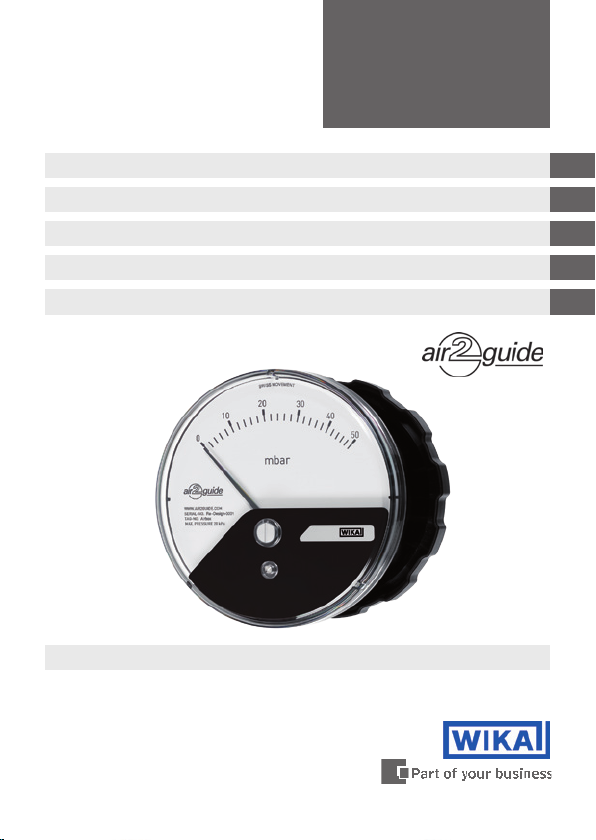
Dierential pressure gauges models A2G-10/15
Dierenzdruckmessgeräte Typen A2G-10/15
Manomètres pour pression diérentielle types A2G-10/15
Manómetros de presión diferencial modelos A2G-10/15
Manometri per pressione dierenziale modellos A2G-10/15
Dierential pressure gauge model A2G-10
GB
D
F
E
I
Page 2

GB
Operating instructions model A2G-10/15 Page 3-12
D
Betriebsanleitung Typ A2G-10/15 Seite 13-22
F
Mode d'emploi type A2G-10/15 Page 23-32
E
Manual de instrucciones modelo A2G-10/15 Página 33-42
I
Manuale d'uso modello A2G-10/15 Pagina 43-52
© 2010 WIKA Alexander Wiegand SE & Co. KG
All rights reserved. / Alle Rechte vorbehalten.
®
WIKA
is a registered trademark in various countries.
®
WIKA
ist eine geschützte Marke in verschiedenen Ländern.
Prior to starting any work, read the operating instructions!
Keep for later use!
Vor Beginn aller Arbeiten Betriebsanleitung lesen!
Zum späteren Gebrauch aufbewahren!
Lire le mode d‘emploi avant de commencer toute opération !
A conserver pour une utilisation ultérieure !
¡Leer el manual de instrucciones antes de comenzar cualquier trabajo!
¡Guardar el manual para una eventual consulta!
Prima di iniziare ad utilizzare lo strumento, leggere il manuale d‘uso!
Conservare per future consultazioni!
2
WIKA operating instructions air2guide models A2G-10, A2G-15
40197310.04 04/2012 GB/D/F/E/I
Page 3

Contents
Contents
1. General information 4
2. Safety 5
3. Specications 6
Design and function
4.
5. Transport, packaging and storage 8
6. Commissioning, operation 8
7. Output signal (model A2G-15) 11
8. Zero point adjustment 11
9. Options and accessories 12
10. Maintenance and cleaning 12
11. Disposal 12
7
GB
40197310.04 04/2012 GB/D/F/E/I
WIKA operating instructions air2guide models A2G-10, A2G-15
3
Page 4

1. General information
1. General information
■
The pressure gauge described in the operating instructions has
been designed and manufactured using state-of-the-art technology.
All components are subject to stringent quality and environmental
GB
criteria during production. Our management systems are certied to
ISO 9001 and ISO 14001.
■
These operating instructions contain important information on
handling the instrument. Working safely requires that all safety
instructions and work instructions are observed.
■
Observe the relevant local accident prevention regulations and
general safety regulations for the instrument's range of use.
■
The operating instructions are part of the product and must be kept
in the immediate vicinity of the instrument and readily accessible to
skilled personnel at any time.
■
Skilled personnel must have carefully read and understood the
operating instructions, prior to beginning any work.
■
The manufacturer's liability is void in the case of any damage caused
by using the product contrary to its intended use, non-compliance
with these operating instructions, assignment of insuciently
qualied skilled personnel or unauthorised modications to the
instrument.
■
The general terms and conditions contained in the sales documentation shall apply.
■
Subject to technical modications.
■
Further information:
- Internet address: www.wika.de / www.wika.com
www.air2guide.com
- Relevant data sheet: PM 07.40 and PV 17.40
4
WIKA operating instructions air2guide models A2G-10, A2G-15
40197310.04 04/2012 GB/D/F/E/I
Page 5
1. General information / 2. Safety
Explanation of symbols
WARNING!
... indicates a potentially dangerous situation which can
result in serious injury or death if not avoided.
Information
… points out useful tips, recommendations and information
for ecient and trouble-free operation.
2. Safety
WARNING!
Before installation, commissioning and operation, ensure
that the appropriate pressure gauge has been selected in
terms of measuring range, design and specic measuring
conditions.
Non-observance can result in serious injury and/or damage
to the equipment.
Further important safety instructions can be found in the
individual chapters of these operating instructions.
2.1 Intended use
GB
This pressure gauge is designed for measuring very low pressures in
dry, clean, non-aggressive gases, primarily air.
The instrument has been designed and built solely for the intended use
described here, and may only be used accordingly.
The manufacturer shall not be liable for claims of any type based on
operation contrary to the intended use.
40197310.04 04/2012 GB/D/F/E/I
WIKA operating instructions air2guide models A2G-10, A2G-15
5
Page 6
2. Safety / 3. Specications
2.2 Personnel qualication
WARNING!
Risk of injury if qualication is insucient!
GB
Improper handling can result in considerable injury and
damage to equipment.
■
The activities described in these operating instructions
may only be carried out by skilled personnel who have
the qualications described below.
Skilled personnel
Skilled personnel are understood to be personnel who, based on their
technical training, knowledge of measurement and control technology
and on their experience and knowledge of country-specic regulations,
current standards and directives, are capable of carrying out the work
described and independently recognising potential hazards.
Explanation of symbols
CE, Communauté Européenne
Instruments bearing this mark comply with the relevant
European directives.
3. Specications
Pressure limitation
Steady: Full scale value
Fluctuating: Full scale value
Overpressure safety
Plus and minus side 20 kPa
Max. working pressure (static pressure)
20 kPa
6
WIKA operating instructions air2guide models A2G-10, A2G-15
40197310.04 04/2012 GB/D/F/E/I
Page 7

3. Specications / 4. Design and function
Process connection
In accordance with the general technical regulations for pressure
gauges (e.g. EN 837-2 "Selection and installation recommendations for
pressure gauges"), plastic, G 1/8 female threads
Permissible temperature
Ambient: -30 … +80 °C
Medium: -16 … +50 °C
Temperature eect
When the temperature of the measuring system deviates from the
reference temperature (+20 °C): max. ±0.5 %/10 K of full scale value
Ingress protection
IP 54 per EN 60529 / lEC 529, optional IP 65
EMC directive
Per EN 61000-6-4 and EN 61000-6-2 (cable length max 30 m)
For further specications see WIKA data sheet PM 07.40, PV 17.40 and
the order documentation.
4. Design and function
Description
■
Nominal size 110 mm
GB
■
The instruments measure the pressure by means of diaphragms
(silicone)
■
The measuring characteristics are in accordance with the EN 837-3
standard and ventilation and air conditioning (VAC) regulations
Scope of delivery
Cross-check the scope of delivery with the delivery note.
40197310.04 04/2012 GB/D/F/E/I
WIKA operating instructions air2guide models A2G-10, A2G-15
7
Page 8

5. Transport, packaging ... / 6. Commissioning, operation
5. Transport, packaging and storage
5.1 Transport
Check the pressure gauge for any damage that may have been caused
by transport. Obvious damage must be reported immediately.
GB
5.2 Packaging
Do not remove packaging until just before mounting.
Keep the packaging as it will provide optimum protection during transport (e.g. change in installation site, sending for repair).
5.3 Storage
Permissible conditions at the place of storage
Storage temperature: -30 ... +80 °C
Protect the instruments from moisture and dust.
6. Commissioning, operation
Installation and mechanical connection
In accordance with the general technical regulations for pressure
gauges (e.g. EN 837-2 "Selection and installation recommendations for
pressure gauges").
■
Process connection lower mount (LM) or back mount (BM)
■
Protect measuring instruments from contamination, high temperature
changes and vibrations
■
air2guide standard gauges are calibrated in vertical position and
should be installed in the same position to avoid loss of class
accuracy. If a dierent installation position is required please specify
when ordering. Gauges with high pressure ranges can be installed in
dierent non-vertical mounting position, by simply adjusting the zero
point.
8
WIKA operating instructions air2guide models A2G-10, A2G-15
40197310.04 04/2012 GB/D/F/E/I
Page 9
6. Commissioning, operation
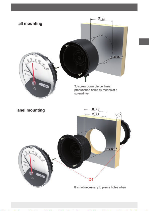
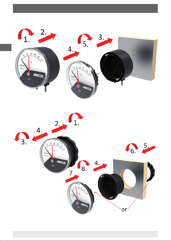
Wall mounting
Panel mounting
To screw down pierce three
prepunched holes by means of a
screwdriver
GB
It is not necessary to pierce holes when
carrying out assembly using a threaded
bezel
40197310.04 04/2012 GB/D/F/E/I
WIKA operating instructions air2guide models A2G-10, A2G-15
9
Page 10
6. Commissioning, operation
Detailed mounting steps for surface mounting
GB
Detailed mounting steps for panel mounting
After tting the
measuring element
into the case it can be
moved in a clockwise
and counterclockwise
direction respectively
for 15 angular degrees
in order to ensure
precise horizontal positioning of the instrument.
10
WIKA operating instructions air2guide models A2G-10, A2G-15
40197310.04 04/2012 GB/D/F/E/I
Page 11
6. Commissioning, operation ... 8. Zero point adjustment
Commissioning
■
During the commissioning process pressure surges must be avoided
at all costs
■
Install the pressure connection according to the symbols
⊕ high pressure ⊖ low pressure
■
Use the pressure gauge only if the diaphragm is undamaged and if it
is in perfect condition with regard to safety.
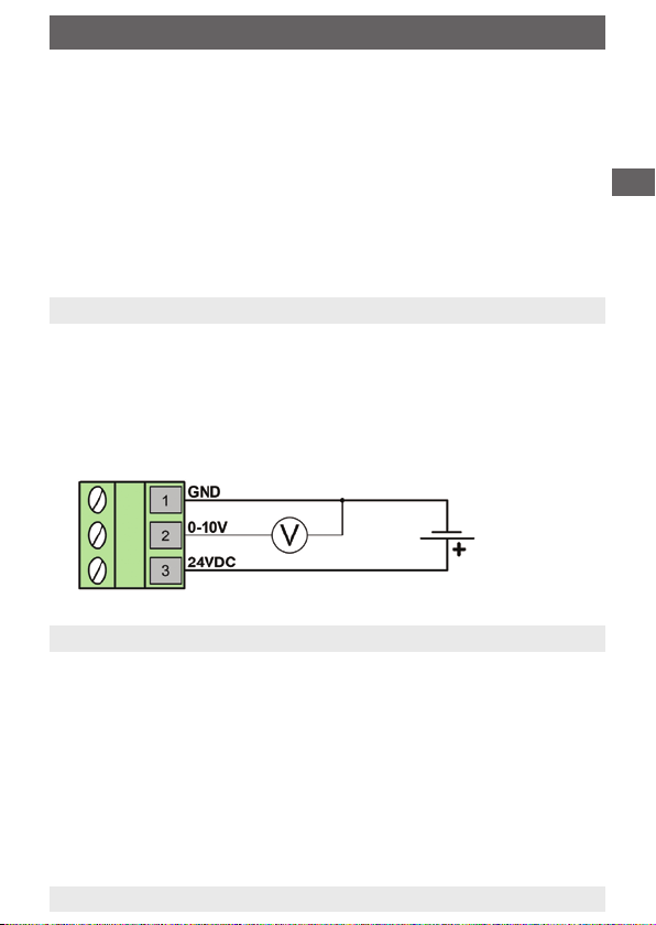
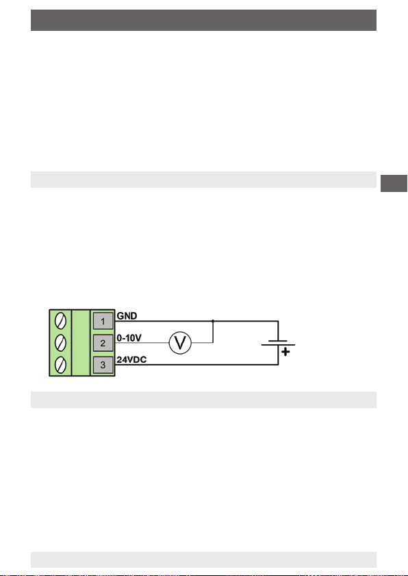
7. Output signal (model A2G-15)
Output signal 0 … 10 V, 3-wire
Power supply UB DC 15 ... 35 V
Measuring accuracy of sensor
±3 % of end value of measuring range
Electrical connection M12 cable gland with screw terminals
Terminal conguration
Power supply
DC 15 ... 35 V
8. Zero point adjustment
In general, the zero point should only be checked and adjusted after the
system has been depressurised.
Mechanical and electrical zero point
If there is a zero point deviation (in depressurised condition), the
mechanical as well as the electrical zero point can be adjusted simultaneously by turning the adjustment screw located in the front.
GB
40197310.04 04/2012 GB/D/F/E/I
WIKA operating instructions air2guide models A2G-10, A2G-15
11
Page 12

9. Options and accessories ... 11. Disposal
9. Options and accessories
Mark pointer
The mark pointer indicates the maximum allowable dierential pressure
on the dial. It can be adjusted manually to the desired value.
GB
Standard accessories
■
3 mounting screws
■
for wall mounting straight threaded pressure connection G 1/8 for
inner diameter 4 or 6 mm
■
for panel mounting angled threaded pressure connection G 1/8 for
inner diameter 4 or 6 mm
Measuring hose
Plastic, for inner diameter 4 or 6 mm, reels available at 25 m
10. Maintenance and cleaning
WIKA dierential pressure gauges are maintenance-free and oer long
service life provided they are handled and operated properly.
Clean the instruments with a moist cloth (soap water).
Repairs must only be carried out by the manufacturer or appropriately
qualied skilled personnel.
11. Disposal
Incorrect disposal can put the environment at risk.
Dispose of instrument components and packaging materials in an
environmentally compatible way and in accordance with the country-
specic waste disposal regulations.
12
WIKA operating instructions air2guide models A2G-10, A2G-15
40197310.04 04/2012 GB/D/F/E/I
Page 13
Inhalt
Inhalt
1. Allgemeines 14
2. Sicherheit 15
3. Technische Daten 16
Aufbau und Funktion
4.
5. Transport, Verpackung und Lagerung 18
6. Inbetriebnahme, Betrieb 18
7. Ausgangssignal (Typ A2G-15) 21
8. Nullpunkteinstellung 21
9. Optionen und Zubehör 22
10. Wartung und Reinigung 22
11. Entsorgung 22
17
D
40197310.04 04/2012 GB/D/F/E/I
WIKA Betriebsanleitung air2guide Typen A2G-10, A2G-15
13
Page 14

1. Allgemeines
1. Allgemeines
■
Das in der Betriebsanleitung beschriebene Druckmessgerät wird
nach den neuesten Erkenntnissen konstruiert und gefertigt.
Alle Komponenten unterliegen während der Fertigung strengen
Qualitäts- und Umweltkriterien. Unsere Managementsysteme sind
nach ISO 9001 und ISO 14001 zertiziert.
D
■
Diese Betriebsanleitung gibt wichtige Hinweise zum Umgang mit
dem Gerät. Voraussetzung für sicheres Arbeiten ist die Einhaltung
aller angegebenen Sicherheitshinweise und Handlungsanweisungen.
■
Die für den Einsatzbereich des Gerätes geltenden örtlichen Unfallverhütungsvorschriften und allgemeinen Sicherheitsbestimmungen
einhalten.
■
Die Betriebsanleitung ist Produktbestandteil und muss in unmittelbarer Nähe des Gerätes für das Fachpersonal jederzeit zugänglich
aufbewahrt werden.
■
Das Fachpersonal muss die Betriebsanleitung vor Beginn aller
Arbeiten sorgfältig durchgelesen und verstanden haben.
■
Die Haftung des Herstellers erlischt bei Schäden durch bestimmungswidrige Verwendung, Nichtbeachten dieser Betriebsanleitung,
Einsatz ungenügend qualizierten Fachpersonals sowie eigenmächtiger Veränderung am Gerät.
■
Es gelten die allgemeinen Geschäftsbedingungen in den Verkaufsunterlagen.
■
Technische Änderungen vorbehalten.
■
Weitere Informationen:
- Internet-Adresse: www.wika.de / www.wika.com
www.air2guide.com
- zugehöriges Datenblatt: PM 07.40 und PV 17.40
14
WIKA Betriebsanleitung air2guide Typen A2G-10, A2G-15
40197310.04 04/2012 GB/D/F/E/I
Page 15
1. Allgemeines / 2. Sicherheit
Symbolerklärung
WARNUNG!
… weist auf eine möglicherweise gefährliche Situation hin,
die zum Tod oder zu schweren Verletzungen führen kann,
wenn sie nicht gemieden wird.
Information
… hebt nützliche Tipps und Empfehlungen sowie Infor-
mationen für einen ezienten und störungsfreien Betrieb
hervor.
2. Sicherheit
WARNUNG!
Vor Montage, Inbetriebnahme und Betrieb sicherstellen,
dass das richtige Druckmessgerät hinsichtlich Messbe-
reich, Ausführung und spezischen Messbedingungen
ausgewählt wurde.
Bei Nichtbeachten können schwere Körperverletzungen
und/oder Sachschäden auftreten.
Weitere wichtige Sicherheitshinweise benden sich in den
einzelnen Kapiteln dieser Betriebsanleitung.
2.1 Bestimmungsgemäße Verwendung
D
Dieses Druckmessgerät dient zum Messen von sehr niedrigen Drücken
bei trockenen, sauberen, nicht aggressiven Gasen, hauptsächlich Luft.
Das Gerät ist ausschließlich für den hier beschriebenen bestimmungsgemäßen Verwendungszweck konzipiert und konstruiert und darf nur
dementsprechend verwendet werden.
Ansprüche jeglicher Art aufgrund von nicht bestimmungsgemäßer
Verwendung sind ausgeschlossen.
40197310.04 04/2012 GB/D/F/E/I
WIKA Betriebsanleitung air2guide Typen A2G-10, A2G-15
15
Page 16
2. Sicherheit / 3. Technische Daten
2.2 Personalqualikation
WARNUNG!
Verletzungsgefahr bei unzureichender Qualikation!
Unsachgemäßer Umgang kann zu erheblichen Personenund Sachschäden führen.
■
D
Die in dieser Betriebsanleitung beschriebenen Tätigkeiten nur durch Fachpersonal nachfolgend beschrie-
bener Qualikation durchführen lassen.
Fachpersonal
Das Fachpersonal ist aufgrund seiner fachlichen Ausbildung, seiner
Kenntnisse der Mess- und Regelungstechnik und seiner Erfahrungen
sowie Kenntnis der landesspezischen Vorschriften, geltenden Normen
und Richtlinien in der Lage, die beschriebenen Arbeiten auszuführen
und mögliche Gefahren selbstständig zu erkennen.
Symbolerklärung
CE, Communauté Européenne
Geräte mit dieser Kennzeichnung stimmen überein mit den
zutreenden europäischen Richtlinien.
3. Technische Daten
Druckbelastbarkeit
Ruhebelastung: Skalenendwert
Wechselbelastung: Skalenendwert
Überlastbarkeit
Minus- und Plusseite 20 kPa
Max. Betriebsdruck (statischer Druck)
20 kPa
16
WIKA Betriebsanleitung air2guide Typen A2G-10, A2G-15
40197310.04 04/2012 GB/D/F/E/I
Page 17

3. Technische Daten / 4. Aufbau und Funktion
Prozessanschluss
Entsprechend den allgemeinen technischen Regeln für Druckmessgeräte (z. B. EN 837-2 "Auswahl- und Einbauempfehlungen für Druck-
messgeräte"), Kunststo, G 1/8 Innengewinde
Zulässige Temperatur
Umgebung: -30 … +80 °C
Messsto: -16 … +50 °C
Temperatureinuss
Bei Abweichung von der Referenztemperatur (+20 °C) am Messsystem:
max. ±0,5 %/10 K vom jeweiligen Skalenendwert
Schutzart
IP 54 nach EN 60529 / lEC 529, optional IP 65
EMV-Richtlinie
Nach EN 61000-6-4 und EN 61000-6-2 (Kabellänge max. 30 m)
Weitere technische Daten siehe WIKA-Datenblatt PM 07.40, PV 17.40
und Bestellunterlagen.
4. Aufbau und Funktion
Beschreibung
■
Nenngröße 110 mm
D
■
Die Geräte erfassen den zu messenden Druck mit Trennmembranen
(Silikon)
■
Die messtechnischen Eigenschaften entsprechen der Norm
EN 837-3 und den Raumlufttechnik-(RLT-)Richtlinien
Lieferumfang
Lieferumfang mit dem Lieferschein abgleichen.
40197310.04 04/2012 GB/D/F/E/I
WIKA Betriebsanleitung air2guide Typen A2G-10, A2G-15
17
Page 18

5. Transport, Verpackung ... / 6. Inbetriebnahme, Betrieb
5. Transport, Verpackung und Lagerung
5.1 Transport
Druckmessgerät auf eventuell vorhandene Transportschäden untersu-
chen. Oensichtliche Schäden unverzüglich mitteilen.
5.2 Verpackung
D
Verpackung erst unmittelbar vor der Montage entfernen.
Die Verpackung aufbewahren, denn diese bietet bei einem Transport
einen optimalen Schutz (z. B. wechselnder Einbauort, Reparatursendung).
5.3 Lagerung
Zulässige Bedingungen am Lagerort
Lagertemperatur: -30 ... +80 °C
Geräte vor Feuchtigkeit und Staub schützen.
6. Inbetriebnahme, Betrieb
Installation und mechanischer Anschluss
Entsprechend den allgemeinen technischen Regeln für Druckmessgeräte (z. B. EN 837-2 "Auswahl- und Einbauempfehlungen für Druckmessgeräte").
■
Prozessanschluss unten bzw. rückseitig
■
Messgeräte vor Verschmutzung und starken Temperaturschwankungen und Vibrationen schützen
■
Die air2guide Standardgeräte sind in vertikaler Lage der Membrane
justiert und sollten deshalb auch so montiert werden um die Klassengenauigkeit einzuhalten. Wenn air2guide Geräte in einer anderen
Position montiert werden müssen, sollte dies im Bestellungsprozess
speziziert werden. Höhere Messbereiche können durch Verstellung
der Nullpunktkorrektur in anderer Position als vertikal eingesetzt
werden.
18
WIKA Betriebsanleitung air2guide Typen A2G-10, A2G-15
40197310.04 04/2012 GB/D/F/E/I
Page 19

6. Inbetriebnahme, Betrieb
Wandmontage
Tafeleinbau
Zum Anschrauben sind die drei
vorgestanzten Löcher mit einem
Schraubenzieher durchzustoßen
D
Bei Einbau mit Schraubring ist das
Durchstoßen der Löcher nicht notwendig
40197310.04 04/2012 GB/D/F/E/I
WIKA Betriebsanleitung air2guide Typen A2G-10, A2G-15
19
Page 20

6. Inbetriebnahme, Betrieb
Detaillierte Montageschritte der Wandmontage
D
Detaillierte Montageschritte für den Tafeleinbau
Nach dem Einsetzen
des Messelementes
in das Gehäuse kann
das Messelement
im Uhrzeiger- und
Gegenuhrzeigersinn
jeweils 15 Winkelgrade
verstellt werden um
eine exakte waagrechte Positionierung des Gerätes zu gewährleisten.
20
WIKA Betriebsanleitung air2guide Typen A2G-10, A2G-15
40197310.04 04/2012 GB/D/F/E/I
Page 21

6. Inbetriebnahme, Betrieb ... 8. Nullpunkteinstellung
Inbetriebnahme
■
Bei Inbetriebnahme unbedingt Druckstöße vermeiden
■
Montage des Druckanschlusses nach angebrachten Symbolen
⊕ hoher Druck, ⊖ niedriger Druck
■
Setzen Sie das Druckmessgerät nur ein, wenn die Membrane
unbeschädigt ist, und in sicherheitstechnisch einwandfreiem
Zustand.
7. Ausgangssignal (Typ A2G-15)
Ausgangssignal 0 … 10 V, 3-Leiter
Hilfsenergie UB DC 15 ... 35 V
Messgenauigkeit Sensor ±3 % vom Messbereichsendwert
Elektrischer Anschluss M12 Kabelverschraubung mit
Schraubklemmen
Klemmenbelegung
Hilfsenergie
DC 15 ... 35 V
8. Nullpunkteinstellung
D
Im Allgemeinen erfolgt die Überprüfung und Einstellung des Nullpunktes
im drucklosen Zustand.
Mechanischer und elektrischer Nullpunkt
Bei Abweichung des Zeigers vom Nullpunkt (im drucklosen Zustand)
kann eine Nullpunktkorrektur über die Nullpunkteinstellung (Schraube)
erfolgen. Der mechanische und elektrische Nullpunkt werden durch
Drehen der Nullpunktschraube (an der Frontseite des Gerätes) gleichzeitig eingestellt.
40197310.04 04/2012 GB/D/F/E/I
WIKA Betriebsanleitung air2guide Typen A2G-10, A2G-15
21
Page 22

9. Optionen und Zubehör ... 11. Entsorgung
9. Optionen und Zubehör
Markenzeiger
Mit dem Markenzeiger kann der zulässige Dierenzdruck auf dem
Zierblatt angezeigt werden. Er wird von Hand auf den gewünschten
Wert eingestellt.
D
Standardzubehör
■
3 Befestigungsschrauben
■
für Wandmontage gerader Einschraubstutzen G 1/8 für
Innendurchmesser 4 oder 6 mm
■
für Tafeleinbau Winkel-Einschraubstutzen G 1/8 für
Innendurchmesser 4 oder 6 mm
Messschlauch
Kunststo, für Innendurchmesser 4 oder 6 mm, Rollen erhältlich á 25 m
10. Wartung und Reinigung
Die WIKA-Dierenzdruckmessgeräte sind wartungsfrei und zeichnen
sich bei sachgemäßer Behandlung und Bedienung durch eine hohe
Lebensdauer aus.
Reinigen der Geräte mit einem (in Seifenlauge) angefeuchteten Tuch.
Reparaturen sind ausschließlich vom Hersteller oder entsprechend
qualiziertem Fachpersonal durchzuführen.
11. Entsorgung
Durch falsche Entsorgung können Gefahren für die Umwelt entstehen.
Gerätekomponenten und Verpackungsmaterialien entsprechend den
landesspezischen Abfallbehandlungs- und Entsorgungsvorschriften
umweltgerecht entsorgen.
22
WIKA Betriebsanleitung air2guide Typen A2G-10, A2G-15
40197310.04 04/2012 GB/D/F/E/I
Page 23

Sommaire
Sommaire
1. Généralités 4
2. Sécurité 5
3. Spécications 6
Conception et fonction
4.
5. Transport, emballage et stockage 8
6. Mise en service, exploitation 8
7. Signal de sortie (type A2G-15) 11
8. Réglage du point zéro 11
9. Options et accessoires 12
10. Entretien et nettoyage 12
11. Mise au rebut 12
F
7
40197310.04 04/2012 GB/D/F/E/I
Mode d´emploi WIKA air2guide types A2G-10 et A2G-15
23
Page 24

1. Généralités
1. Généralités
■
Le manomètre décrit dans le mode d'emploi est conçu et fabriqué
selon les dernières technologies en vigueur. Tous les composants
sont soumis à des critères de qualité et d'environnement stricts
durant la fabrication. Nos systèmes de gestion sont certiés selon
ISO 9001 et ISO 14001.
■
Ce mode d'emploi donne des indications importantes concernant
F
l'utilisation de l'instrument. Il est possible de travailler en toute
sécurité avec ce produit en respectant toutes les consignes de
sécurité et d'utilisation.
■
Respecter les prescriptions locales de prévention contre les
accidents et les prescriptions générales de sécurité en vigueur pour
le domaine d‘application de l'instrument.
■
Le mode d'emploi fait partie du produit et doit être conservé à
proximité immédiate de l'instrument et être accessible à tout moment
pour le personnel qualié.
■
Le personnel qualié doit, avant de commencer toute opération,
avoir lu soigneusement et compris le mode d'emploi.
■
La responsabilité du fabricant n'est pas engagée en cas de
dommages provoqués par une utilisation non conforme à l'usage
prévu, de non respect de ce mode d'emploi, d'utilisation de
personnel peu qualié de même qu'en cas de modications de
l'instrument eectuées par l'utilisateur.
■
Les conditions générales de vente mentionnées dans les documents
de vente s'appliquent.
■
Sous réserve de modications techniques.
■
Pour obtenir d'autres informations :
- Consulter notre site internet : www.wika.fr / www.wika.com
www.air2guide.com
- Fiche technique correspondante : PM 07.40 et PV 17.40
24
Mode d´emploi WIKA air2guide types A2G-10, A2G-15
40197310.04 04/2012 GB/D/F/E/I
Page 25

1. Généralités / 2. Sécurité
Explication des symboles
AVERTISSEMENT !
… indique une situation présentant des risques susceptibles de provoquer la mort ou des blessures graves si elle
n'est pas évitée.
Information
… met en exergue les conseils et recommandations utiles
de même que les informations permettant d'assurer un
fonctionnement ecace et normal.
2. Sécurité
AVERTISSEMENT !
Avant le montage, la mise en service et le fonctionnement, s'assurer que l'indicateur de pression portable et
le capteur de pression ont été choisi de façon adéquate,
en ce qui concerne la plage de mesure, la version et les
conditions de mesure spéciques.
Un non-respect de cette consigne peut entraîner des
blessures corporelles graves et/ou des dégâts matériels.
Vous trouverez d'autres consignes de sécurité dans les
sections individuelles du présent mode d'emploi.
2.1 Utilisation conforme à l'usage prévu
F
Ce manomètre est pour mesurer de très basse pression de gaz sec,
propre et non agressif, principalement de l’air.
L'instrument est conçu et construit exclusivement pour une utilisation
conforme à l'usage prévu décrit ici et ne doit être utilisé qu'en
conséquence.
Aucune réclamation ne peut être recevable en cas d'utilisation non
conforme à l'usage prévu.
40197310.04 04/2012 GB/D/F/E/I
Mode d´emploi WIKA air2guide types A2G-10 et A2G-15
25
Page 26

2. Sécurité / 3. Spécications
2.2 Qualication du personnel
AVERTISSEMENT !
Danger de blessure en cas de qualication insufsante !
Une utilisation non conforme peut entraîner d'importants
dommages corporels et matériels.
■
F
Les opérations décrites dans ce mode d'emploi ne
doivent être eectuées que par un personnel ayant la
qualication décrite ci-après.
Personnel qualié
Le personnel qualié est, en raison de sa formation spécialisée, de
ses connaissances dans le domaine de la technique de mesure et de
régulation et de ses expériences de même que de sa connaissance
des prescriptions nationales, des normes et directives en vigueur,
en mesure d'eectuer les travaux décrits et de reconnaître
automatiquement les dangers potentiels.
Explication des symboles
CE, Communauté Européenne
Les instruments avec ce marquage sont conformes aux
directives européennes pertinentes.
3. Spécications
Plages d' utilisation
Charge statique : Fin d'échelle
Charge dynamique : Fin d'échelle
Surpression admissible
Coté + et - 20 kPA
Pression de service max. (pression statique)
20 kPa
26
Mode d´emploi WIKA air2guide types A2G-10, A2G-15
40197310.04 04/2012 GB/D/F/E/I
Page 27

3. Spécications / 4. Conception et fonction
Raccord process
Conformément aux règles techniques générales pour les manomètres
(par exemple EN 837-2 "Recommandations sur le choix et l’installation
des manomètres"), plastique, taraudage G 1/8
Température admissible
Ambiante : -30 … +80 °C
Fluide : -16 … +50 °C
Eet de la température
Lorsque la température du système de mesure dévie de la température
de référence (+20 °C) : max. ±0,5 %/10 K de la valeur de pleine échelle
Indice de protection
IP 54 selon EN 60529 / lEC 529, en option IP 65
Directive CEM
Selon EN 61000-6-4 et EN 61000-6-2 (longueur du câble max. 30 m)
Pour de plus amples spécications, voir la che technique WIKA
PM 07.40, PV 17.40 et la documentation de commande.
4. Conception et fonction
Description
■
Diamètre : 110 mm
■
Les appareils mesurent la pression par le biais de membranes
(Silicone)
F
■
Les caractéristiques techniques de mesure correspondent à la
norme EN 837-3 et les directives pour les installations de ventilation
et d’air conditionné (VAC)
Détail de la livraison
Comparer le détail de la livraison avec le bordereau de livraison.
40197310.04 04/2012 GB/D/F/E/I
Mode d´emploi WIKA air2guide types A2G-10 et A2G-15
27
Page 28

5. Transport, emballage ... / 6. Mise en service, exploitation
5. Transport, emballage et stockage
5.1 Transport
Vérier s'il existe des dégâts sur le manomètre liés au transport.
Communiquer immédiatement les dégâts constatés.
5.2 Emballage
N'enlever l'emballage qu'avant le montage.
Conserver l'emballage, celui-ci ore, lors d'un transport, une protection
F
optimale (par ex. changement de lieu d'utilisation, renvoi pour
réparation).
5.3 Stockage
Conditions admissibles sur le lieu de stockage
Température de stockage : -30 ... +80 °C
Protégez les instruments contre l'humidité et la poussière.
6. Mise en service, exploitation
Installation et raccordement mécanique
Conformément aux règles techniques générales pour les manomètres
(par ex. EN 837-2 "Recommandations sur le choix et l'installation des
manomètres").
■
Raccord process vertical (LM) ou arrière (BM)
■
Protégez les instruments de mesure contre la contamination, les
variations de température élevées et les vibrations
■
Les appareils standard air2guide sont étalonnés en position verticale
et doivent donc également être montés dans cette position pour
conserver leur classe de précision. Dans le cas ou une autre position
de montage serait requise, il est recommandé de l‘indiquer à la
commande. Les appareils avec les étendues de mesure les plus
élevées peuvent être utilisés en standard dans une position autre
que verticale en réglant simplement le point zéro de l‘indication.
28
Mode d´emploi WIKA air2guide types A2G-10, A2G-15
40197310.04 04/2012 GB/D/F/E/I
Page 29
6. Mise en service, exploitation
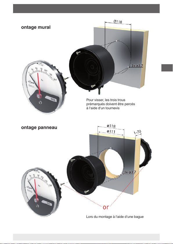
Montage mural
Montage panneau
Pour visser, les trois trous
prémarqués doivent être percés
à l‘aide d‘un tournevis
F
Lors du montage à l‘aide d‘une bague
letée, il n‘est pas nécessaire de percer
les trous
40197310.04 04/2012 GB/D/F/E/I
Mode d´emploi WIKA air2guide types A2G-10 et A2G-15
29
Page 30

6. Mise en service, exploitation
Etapes détaillées du montage mural
F
Etapes détaillées du montage panneau
Après le montage de
l‘élément de mesure
dans le boîtier,
l‘élément de mesure
peut être réglé dans
le sens des aiguilles
d‘une montre et dans
le sens contraire
des aiguilles d‘une montre sur 15 degrés d‘angle an de garantir un
positionnement horizontal précis de l‘appareil.
30
Mode d´emploi WIKA air2guide types A2G-10, A2G-15
40197310.04 04/2012 GB/D/F/E/I
Page 31

6. Mise en service ... 8. Réglage du point zéro
Mise en service
■
Lors de la mise en service il faut absolument éviter les coups de
bélier
■
Montage du raccord de pression conformément aux symboles
apposés ⊕ haute pression ⊖ basse pression
■
N‘utilisez le manomètre que s‘il est dans un état irréprochable du
point de vue de la sécurité.
7. Signal de sortie (type A2G-15)
Signal de sortie 0 … 10 V, 3 ls
Alimentation UB 15 ... 35 VDC
Précision de mesure du capteur
±3 % de l'étendue de mesure
Raccordement électrique M12 presse-étoupe avec bornes à vis
Conguration des bornes
Alimentation
15 ... 35 VDC
8. Réglage du point zéro
La vérication et le réglage du zéro se font hors pression.
Point zéro mécanique et électrique
En cas d’un décalage du point zéro (appareil hors pression), le réglage
du point zéro électrique et mécanique est possible simultanément en
tournant la vis de réglage située sur la face avant.
F
40197310.04 04/2012 GB/D/F/E/I
Mode d´emploi WIKA air2guide types A2G-10 et A2G-15
31
Page 32

9. Options et accessoires ... 11. Mise au rebut
9. Options et accessoires
Aiguille réglable
L‘aiguille réglable permet d‘acher la pression diérentielle sur le
cadran. Elle se règle manuellement sur la valeur souhaitée.
Accessoires standards
■
3 vis de montage
■
Solution pour montage mural: bague leté droit G 1/8 pour
F
diamètre intérieur de 4 ou 6 mm
■
Solution pour montage panneau: bague leté coudé G 1/8 pour
diamètre intérieur de 4 ou 6 mm
Flexible de raccordement
Plastique, pour diamètre intérieur 4 ou 6 mm, bobine de 25 mètres
10. Entretien et nettoyage
WIKA manomètres pour pression diérentielle ne nécessitent aucun
entretien et orent une longue durée de vie à condition qu'ils soient
manipulés et actionnés correctement.
Nettoyez les instruments avec un chion humide (eau savonneuse).
Les réparations doivent être eectuées exclusivement par le fabricant
ou par un personnel qualié.
11. Mise au rebut
Une mise au rebut inadéquate peut entraîner des dangers pour
l'environnement.
Eliminer les composants des instruments et les matériaux d'emballage
conformément aux prescriptions nationales pour le traitement et
l'élimination des déchets et aux lois de protection de l'environnement en
vigueur.
32
Mode d´emploi WIKA air2guide types A2G-10, A2G-15
40197310.04 04/2012 GB/D/F/E/I
Page 33

Contenido
Contenido
1. Información general 14
2. Seguridad 15
3. Datos técnicos 16
Diseño y función
4.
5. Transporte, embalaje y almacenamiento 18
6. Puesta en servicio, funcionamiento 18
7. Señal de salida (modelo A2G-15) 21
8. Ajuste del punto cero 21
9. Opciones y accesorios 22
10. Mantenimiento y limpieza 22
11. Eliminación de residuos 22
17
E
40197310.04 04/2012 GB/D/F/E/I
WIKA manual de instrucciones air2guide modelos A2G-10, A2G-15
33
Page 34

1. Información general
1. Información general
■
El manómetro descrito en el manual de instrucciones está
construido y fabricado según los conocimientos actuales. Todos los
componentes están sujetos a rigurosos criterios de calidad y medio
ambiente durante la producción. Nuestros sistemas de gestión están
certicados según ISO 9001 e ISO 14001.
■
Este manual de instrucciones proporciona indicaciones importantes
acerca del manejo del instrumento. Para que el trabajo con este
instrumento sea seguro es imprescindible cumplir con todas las
E
instrucciones de seguridad y manejo indicadas.
■
Cumplir siempre las normativas sobre la prevención de accidentes
y las normas de seguridad en vigor en el lugar de utilización del
instrumento.
■
El manual de instrucciones es una parte integrante del instrumento
y debe guardarse en la proximidad del mismo para que el personal
especializado pueda consultarlo en cualquier momento.
■
El personal especializado debe haber leído y entendido el manual
de instrucciones antes de comenzar cualquier trabajo.
■
El fabricante queda exento de cualquier responsabilidad en caso de
daños causados por un uso no conforme a la nalidad prevista, la
inobservancia del presente manual de instrucciones, un manejo por
personal insucientemente cualicado así como una modicación no
autorizada del instrumento.
■
Se aplican las condiciones generales de venta incluidas en la
documentación de venta.
■
Modicaciones técnicas reservadas.
■
Para obtener más informaciones consultar:
- Página web: www.wika.de / www.wika.com
www.air2guide.com
- Hoja técnica correspondiente: PM 07.40 y PV 17.40
34
WIKA manual de instrucciones air2guide modelos A2G-10, A2G-15
40197310.04 04/2012 GB/D/F/E/I
Page 35

1. Información general / 2. Seguridad
Explicación de símbolos
¡ADVERTENCIA!
... indica una situación probablemente peligrosa que pueda
causar la muerte o lesiones graves si no se evita.
Información
... destaca consejos y recomendaciones útiles así como
informaciones para una utilización ecaz y libre de fallos.
2. Seguridad
¡ADVERTENCIA!
Antes del montaje, la puesta en servicio y el
funcionamiento asegurarse de que se haya seleccionado
el manómetro adecuado con respecto a rango de medida,
versión y condiciones de medición especícas.
Riesgo de lesiones graves y/o daños materiales en caso
de inobservancia.
Los distintos capítulos de este manual de instrucciones
contienen otras importantes indicaciones de seguridad.
2.1 Uso conforme a lo previsto
E
Este manómetro se utiliza para medir presiones muy bajas con gases
secos, limpios y no agresivos, sobre todo aire.
El instrumento ha sido diseñado y construido únicamente para la
nalidad aquí descrita y debe utilizarse en conformidad a la misma.
No se admite ninguna reclamación debido a un manejo no adecuado.
40197310.04 04/2012 GB/D/F/E/I
WIKA manual de instrucciones air2guide modelos A2G-10, A2G-15
35
Page 36

2. Seguridad / 3. Datos técnicos
2.2 Cualicación del personal
¡ADVERTENCIA!
¡Riesgo de lesiones debido a una insuciente cualicación!
Un manejo no adecuado puede causar considerables
daños personales y materiales.
■
Las actividades descritas en este manual de instrucciones deben realizarse únicamente por personal especia-
E
lizado con la consiguiente cualicación.
Personal especializado
Debido a su formación profesional, a sus conocimientos de la técnica
de regulación y medición así como a su experiencia y su conocimiento
de las normativas, normas y directivas vigentes en el país de utilización
el personal especializado es capaz de ejecutar los trabajos descritos y
reconocer posibles peligros por sí solo.
Explicación de símbolos
CE, Communauté Européenne
Los instrumentos con este marcaje cumplen las directivas
europeas aplicables.
3. Datos técnicos
Presión admisible
Carga estática: Valor nal de escala
Carga dinámica: Valor nal de escala
Protección contra la sobrepresión
20 kPa
Presión máx. de trabajo (presión estática)
20 kPa
36
WIKA manual de instrucciones air2guide modelos A2G-10, A2G-15
40197310.04 04/2012 GB/D/F/E/I
Page 37

3. Datos técnicos / 4. Diseño y función
Conexión a proceso
Conforme a las reglas técnicas generales para manómetros (por
ejemplo EN 837-2 "Recomendaciones relativas a la selección y montaje
de manómetros"), plástico, rosca hembra G 1/8
Temperatura admisible
Ambiente: -30 … +80 °C
Medio: -16 … +50 °C
Inuencia de temperatura
En caso de desviación de la temperatura de referencia en el sistema de
medición (+20°C): máx. ±0,5 %/10 K del valor nal de escala correspondiente
Tipo de protección
IP 54 según EN 60529 / lEC 529, optional IP 65
Directiva de EMC
Según EN 61000-6-4 y EN 61000-6-2 (longitud de cable max. 30 m)
Para más datos técnicos véase la hoja técnica de WIKA PM 07.40,
PV 17.40 y la documentación de pedido.
4. Diseño y función
Descripción
■
Diámetro nominal 110 mm
E
■
Los instrumentos registran la presión a medir con una membrana de
separación (Silicona)
■
Las características técnicas de medición corresponden a la norma
EN 837-3 y directivas de ventilación y climatización
Volumen de suministro
Comparar mediante el albarán si se han entregado todas las piezas.
40197310.04 04/2012 GB/D/F/E/I
WIKA manual de instrucciones air2guide modelos A2G-10, A2G-15
37
Page 38

5. Transporte, embalaje ... / 6. Puesta en servicio ...
5. Transporte, embalaje y almacenamiento
5.1 Transporte
Comprobar si el manómetro presenta eventuales daños causados en el
transporte. Noticar daños obvios de forma inmediata.
5.2 Embalaje
Sólo quitar el embalaje justo antes del montaje.
Guardar el embalaje ya que es la protección ideal para el transporte
(por ejemplo un cambio del lugar de instalación o un envío del instrumento para posibles reparaciones).
E
5.3 Almacenamiento
Condiciones admisibles en el lugar de almacenamiento
Temperatura de almacenamiento: -30 ... +80 °C
Proteger los instrumentos de medición de humedad y polvo.
6. Puesta en servicio, funcionamiento
Instalación y conexión mecánica
Conforme a las reglas técnicas generales para manómetros (por
ejemplo EN 837-2 Recomendaciones relativas a la selección y montaje
de manómetros).
■
Conexión radial o en el lado posterior
■
Proteger los dispositivos de medición contra la obturación, las
grandes oscilaciones de temperatura y las vibraciones.
■
Los dispositivos estándar air2guide han sido calibrados con la
membrana en posición vertical y, por lo tanto, es necesario montar-
los en esta posición a n de garantizar la clase de precisión de los
dispositivos. Si se pretende montar los dispositivos air2guide en
otra posición, esto deberá especicarse en el pedido. Ajustándo
la corrección del punto cero, es posible adoptar, en otra posición,
rangos de medición más altos como si se tratara de la posición
vertical.
38
WIKA manual de instrucciones air2guide modelos A2G-10, A2G-15
40197310.04 04/2012 GB/D/F/E/I
Page 39
6. Puesta en servicio, funcionamiento
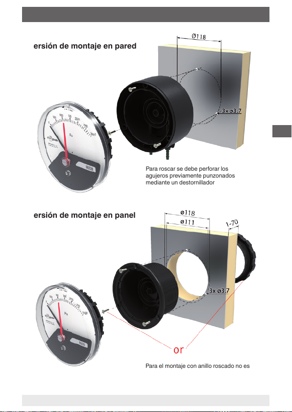
Versión de montaje en pared
Para roscar se debe perforar los
agujeros previamente punzonados
mediante un destornillador
Versión de montaje en panel
E
Para el montaje con anillo roscado no es
necesario perforar los agujeros
40197310.04 04/2012 GB/D/F/E/I
WIKA manual de instrucciones air2guide modelos A2G-10, A2G-15
39
Page 40

6. Puesta en servicio, funcionamiento
Descripción detallada de los pasos para montaje en pared
E
Descripción detallada de los pasos para montaje en panel
Tras la inserción del
elemento sensible en la
caja se puede realizar
el ajuste del elemento
sensible al girarlo 15
grados en el sentido
del reloj o en sentido
contrario para asegurar
una posición horizontal del instrumento.
40
WIKA manual de instrucciones air2guide modelos A2G-10, A2G-15
40197310.04 04/2012 GB/D/F/E/I
Page 41
6. Puesta en servicio ... 8. Ajuste del punto cero
Puesta en servicio
■
Prevenir en todo caso los golpes de presión al poner en servicio el
dispositivo.
■
Entradas de presión identicadas, ⊕ presión alta, ⊖ presión baja
■
Utilizar el manómetro exclusivamente si éste se encuentra en un
estado técnico tal que permita su operación con toda seguridad.
7. Señal de salida (modelo A2G-15)
Señal de salida 0 … 10 V, 3 conductores
Alimentación auxiliar UB DC 15 ... 35 V
Precisión de medida del sensor ±3 % del valor nal del rango de
medida
Conexión eléctrica M12 racor de cable con bornes roscados
Asignación de los bornes de conexión
Alimentación
auxiliar
DC 15 ... 35 V
8. Ajuste del punto cero
El control y ajuste del punto cero deberá efectuarse sin someter el
instrumento a presión.
Punto cero mecánico y eléctrico
Si el indicador ya no está en el punto cero (sin presión), puede realizarse la corrección del punto cero mediante el tornillo de ajuste del punto
cero. El punto cero mecánico y eléctrico se ajustan al mismo tiempo
girando el tornillo (en el lado delantero del aparato).
40197310.04 04/2012 GB/D/F/E/I
WIKA manual de instrucciones air2guide modelos A2G-10, A2G-15
E
41
Page 42

9. Opciones y accesorios ... 11. Eliminación de residuos
9. Opciones y accesorios
Aguja ajustable
Mediante la aguja ajustable puede indicarse la presión diferencial
admisible en la esfera del instrumento. Se ajusta manualmente al valor
deseado.
Accesorios estándar
■
3 tornillos para la jación
■
Montaje en pared rosca recta G 1/8 para un diámetro interior de
E
4 ó 6 mm
■
Montaje en panel rosca angular G 1/8 para un diámetro interior de
4 ó 6 mm
Tubo de medición
Plástico, diámetro interior 4 ó 6 mm, disponible en rollos de 25 m
10. Mantenimiento y limpieza
Los WIKA manómetros de presión diferencial no necesitan
mantenimiento y se distinguen por su prolongada vida útil si se
manejan y operan de forma apropiada.
Limpiar los instrumentos con un trapo húmedo (mojado en lejía de
jabón).
Todas las reparaciones solamente las debe efectuar el fabricante o
personal especializado e instruido.
11. Eliminación de residuos
Una eliminación incorrecta puede provocar peligros para el medio
ambiente.
Eliminar los componentes de los instrumentos y los materiales de
embalaje conforme a los reglamentos relativos al tratamiento de
residuos y eliminación vigentes en el país de utilización.
42
WIKA manual de instrucciones air2guide modelos A2G-10, A2G-15
40197310.04 04/2012 GB/D/F/E/I
Page 43

Contenuti
Contenuti
1. Informazioni generali 4
2. Norme di sicurezza 5
3. Speciche tecniche 6
Design e funzioni
4.
5. Trasporto, imballaggio e stoccaggio 8
6. Messa in servizio, funzionamento 8
7. Segnale in uscita (modello A2G-15) 11
8. Regolazione dello zero 11
9. Opzioni e accessori 12
10. Manutenzione e pulizia 12
11. Smaltimento 12
7
I
40197310.04 04/2012 GB/D/F/E/I
WIKA manuale d‘uso air2guide, modellos A2G-10, A2G-15
43
Page 44

1. Informazioni generali
1. Informazioni generali
■
Il manometro descritto in questo manuale d‘uso è stato progettato e
costruito secondo lo stato dell‘arte della tecnica. Tutti i componenti
sono soggetti a stringenti controlli di qualità ed ambientali durante la
produzione. I nostri sistemi di qualità sono certicati ISO 9001 e ISO
14001.
■
Questo manuale contiene importanti informazioni sull'uso dello
strumento. Lavorare in sicurezza implica il rispetto delle istruzioni di
sicurezza e di funzionamento.
I
■
Osservare le normative locali in tema di prevenzione incidenti e le
regole di sicurezza generali per il campo d'impiego dello strumento.
■
Il manuale d'uso è parte dello strumento e deve essere conservato
nelle immediate vicinanze dello stesso e facilmente accessibile in
ogni momento al personale qualicato.
■
Il manuale d'uso deve essere letto con attenzione e compreso dal
personale qualicato prima dell'inizio di qualsiasi attività.
■
Il costruttore declina ogni responsabilità per qualsiasi danno causato
da un utilizzo scorretto del prodotto, dal non rispetto delle istruzioni riportate in questo manuale, da un impiego di personale non
adeguatamente qualicato oppure da modiche non autorizzate allo
strumento.
■
Si applicano le nostre condizioni generali di vendita, allegate alla
conferma d’ordine.
■
Soggetto a modiche tecniche.
■
Ulteriori informazioni:
- Indirizzo Internet: www.wika.it / www.wika.com
www.air2guide.com
- Scheda tecnica prodotto: PM 07.40 e PV 17.40
44
WIKA manuale d‘uso air2guide, modellos A2G-10, A2G-15
40197310.04 04/2012 GB/D/F/E/I
Page 45

1. Informazioni generali / 2. Norme di sicurezza
Legenda dei simboli
ATTENZIONE!
... indica una situazione di potenziale pericolo che, se non
evitata, può causare ferite gravi o morte.
Informazione
... fornisce suggerimenti utili e raccomandazioni per
l'utilizzo eciente e senza problemi dello strumento.
2. Norme di sicurezza
ATTENZIONE!
Prima dell‘installazione, messa in servizio e funzionamento, assicurarsi che sia stato selezionato il manometro
adatto per quanto riguarda il campo di misura, l'esecuzione
e le condizioni speciche della misura.
La non osservanza può condurre a ferite gravi o danni alle
apparecchiature.
Altre importanti norme di sicurezza sono riportate nei
singoli capitoli di questo manuale d‘uso.
2.1 Destinazione d'uso
Questo manometro è stato progettato per la misura di pressioni molto
basse con gas secchi, puliti e non aggressivi, principalmente aria.
Lo strumento è stato progettato e costruito esclusivamente per la sua
destinazione d'uso e può essere impiegato solo per questa.
Il costruttore non è responsabile per reclami di qualsiasi natura in caso
di utilizzo dello strumento al di fuori del suo impiego consentito.
40197310.04 04/2012 GB/D/F/E/I
WIKA manuale d‘uso air2guide, modellos A2G-10, A2G-15
I
45
Page 46

2. Norme di sicurezza / 3. Speciche tecniche
2.2 Qualicazione personale
ATTENZIONE!
Rischio di infortuni in caso di personale non
qualicato!
L'uso improprio può condurre in ferite gravi o danni alle
apparecchiature.
■
Le attività riportate in questo manuale d'uso possono
essere eettuate solo da personale in possesso delle
qualiche riportate nel seguito.
Personale qualicato
I
Per personale qualicato si intende personale che, sulla base delle
proprie conoscenze tecniche di strumentazione e controllo e e delle
normative nazionali e sulla base della propria esperienza, è in grado
di portare a termine il lavoro e riconoscere autonomamente potenziali
pericoli.
Legenda dei simboli
CE, Communauté Européenne
Gli strumenti riportanti questo marchio sono in accordo con
le relative Direttive Europee.
3. Speciche tecniche
Pressione ammissibile
Statica: Valore di fondo scala
Fluttuante: Valore di fondo scala
Sovraccaricabilità
Lato negativo e positivo 20 kPa
Pressione max. di esercizio (pressione statica)
20 kPa
46
WIKA manuale d‘uso air2guide, modellos A2G-10, A2G-15
40197310.04 04/2012 GB/D/F/E/I
Page 47

3. Speciche tecniche / 4. Design e funzioni
Attacco al processo
In accordo alle normative tecniche generali per strumenti di misura della
pressione (ad esempio: EN 837-2 "Consigli per la scelta ed installazione
di strumenti per la misura di pressione"), plastica, G 1/8 femmina
Temperature consentite
Ambiente: -30 … +80 °C
Fluido: -16 … +50 °C
Inuenza della temperatura
In caso di dierenza tra la temperatura di riferimento (+20 °C) e quella del
sistema di misura: max. ±0,5 %/10 K del rispettivo valore di fondo scala.
Grado di protezione
IP 54 secondo EN 60529 / IEC 529. Opzionale IP 65
Direttiva EMC
Secondo EN 61000-6-4 e EN 61
000-6-2 (lunghezza del cavo max. 30 m)
Per ulteriori informazioni tecniche, fare riferimento alla Scheda Tecnica
WIKA PM 07.40, PV 17.40 ed ai documenti d‘ordine.
4. Design e funzioni
Descrizione
■
Dimensione nominale 110 mm
■
Gli strumenti misurano la pressione per mezzo di membrane
(Silicone)
■
Le caratteristiche degli strumenti di misura rispondono alla normativa
EN 837-3 ed alle normative per l'industria della ventilazione e delle
condizionamento (VAC)
Scopo di fornitura
Controllare lo scopo della fornitura con il documento di consegna /
trasporto.
40197310.04 04/2012 GB/D/F/E/I
WIKA manuale d‘uso air2guide, modellos A2G-10, A2G-15
I
47
Page 48

5. Trasporto, imballaggio ... / 6. Messa in servizio ...
5. Trasporto, imballaggio e stoccaggio
5.1 Trasporto
Vericare che il manometro non abbia subito danni nel trasporto. Danni
evidenti devono essere segnalati tempestivamente.
5.2 Imballo
Rimuovere l'imballo solo appena prima dell'installazione.
Conservare l'imballo per proteggere lo strumento in successivi trasporti
(es. variazione del sito di installazione, invio in riparazaione).
5.3 Stoccaggio
I
Condizioni consentite per lo stoccaggio
Temperatura di stoccaggio: -30 ... +80 °C
Proteggere gli strumenti dall'umidità e dalla polvere.
6. Messa in servizio, funzionamento
Installazione e attacco meccanico
In conformità alle norme tecniche generali per manometri (per esempio:
EN 837-2 "Consigli per la scelta e l'installazione di manometri").
■
Attacco al processo inferiore o posteriore
■
Proteggere gli strumenti di misura da contaminazioni, forti escursioni
termiche e vibrazioni.
■
Gli strumenti standard air2guide sono calibrati con la membrana
in posizione verticale e devono essere pertanto montati in questo
modo, anche per rispettare le speciche di precisione. In caso
debbano essere montati in posizioni diverse, si prega di specicarlo
in fase d’ordine. È possibile ottenere campi di misura più elevati
modicando la correzione del punto zero in una posizione diversa da
quella verticale.
48
WIKA manuale d‘uso air2guide, modellos A2G-10, A2G-15
40197310.04 04/2012 GB/D/F/E/I
Page 49

6. Messa in servizio, funzionamento
Versione per montaggio
a parete
Per il collegamento, utilizzare
un cacciavite per aprire i tre fori
preforati
Versione per montaggio
a pannello
I
Per il montaggio con anello avvitato non è
necessario aprire i fori
40197310.04 04/2012 GB/D/F/E/I
WIKA manuale d‘uso air2guide, modellos A2G-10, A2G-15
49
Page 50

6. Messa in servizio, funzionamento
Fasi di montaggio dettagliate per il montaggio a parete
I
Fasi di montaggio dettagliate per il montaggio a pannello
Dopo aver inserito
l‘elemento di misura
nella custodia è
possibile ruotarlo di
15 gradi in senso
orario o antiorario per
garantire il corretto
posizionamento
orizzontale dello strumento.
50
WIKA manuale d‘uso air2guide, modellos A2G-10, A2G-15
40197310.04 04/2012 GB/D/F/E/I
Page 51

6. Messa in servizio ... 8. Regolazione dello zero
Messa in funzione
■
Durante il processo di prima messa in servizio, si devono evitare in
qualsiasi modo sbalzi di pressione
■
Installare le connessioni di pressione rispettando i simboli applicati:
⊕ lato positivo, ⊖ lato negativo
■
Utilizzare il manometro solo in condizioni tecniche e di sicurezza
perfette.
7. Segnale in uscita (modello A2G-15)
Segnale di uscita 0 … 10 V, 3 li
Alimentazione UB DC 15 ... 35 V
Precisione di misura della sonda
±3 % del valore nale del campo
di misura
Connessione elettrica M12 pressacavo lettato con morsetti a vite
Collegamenti elettrici
Alimentazione
DC 15 ... 35 V
8. Regolazione dello zero
Generalmente, la regolazione dello zero deve avvenire in assenza di
pressione.
Punto zero meccanico ed elettrico
In caso di spostamento dello zero (in assenza di pressione), è possibile
eseguire una correzione dello zero meccanico ed elettrico tramite la vite
di regolazione sul fronte dello strumento.
40197310.04 04/2012 GB/D/F/E/I
WIKA manuale d‘uso air2guide, modellos A2G-10, A2G-15
I
51
Page 52

9. Opzioni e accessori ... 11. Smaltimento
9. Opzioni e accessori
Lancetta di marcatura
La lancetta di marcatura indica la massima pressione dierenziale
ammissibile. Può essere spostata manualmente al valore desiderato.
Accessori standard
■
3 viti di ssaggio
■
Montaggio a parete:
raccordo dritto per tubi con diametro interno 4 o 6 mm
■
Montaggio a pannello:
raccordo angolare per tubi con diametro interno 4 o 6 mm
I
Tubi di connessione
Plastica, per un diametro interno di 4 o 6 mm, disponibili bobine da 25 m
10. Manutenzione e pulizia
Gli apparecchi sono esenti da manutenzione e garantiscono una lunga
durata se trattati e utilizzati in modo appropriato.
Pulire gli apparecchi con un panno umido (con acqua e sapone).
Le riparazioni devono essere eettuate solo dal costruttore o da personale adeguatamente qualicato.
11. Smaltimento
Lo smaltimento inappropriato può provocare rischi per l'ambiente.
Lo smaltimento dei componenti dello strumento e dei materiali di imbal-
laggio deve essere eettuato in modo compatibile ed in accordo alle
normative nazionali.
52
WIKA manuale d‘uso air2guide, modellos A2G-10, A2G-15
40197310.04 04/2012 GB/D/F/E/I
Page 53

WIKA global
Europe
Austria
WIKA Messgerätevertrieb
Ursula Wiegand GmbH & Co. KG
1230 Vienna
Tel. (+43) 1 86916-31
Fax: (+43) 1 86916-34
E-mail: info@wika.at
www.wika.at
Belarus
WIKA Belarus
Ul. Zaharova 50B
Oce 3H
220088 Minsk
Tel. (+375) 17-294 57 11
Fax: (+375) 17-294 57 11
E-mail: info@wika.by
www.wika.by
Benelux
WIKA Benelux
6101 WX Echt
Tel. (+31) 475 535-500
Fax: (+31) 475 535-446
E-mail: info@wika.nl
www.wika.nl
Bulgaria
WIKA Bulgaria EOOD
Bul. „Al. Stamboliiski“ 205
1309 Soa
Tel. (+359) 2 82138-10
Fax: (+359) 2 82138-13
E-mail: t.antonov@wika.bg
Croatia
WIKA Croatia d.o.o.
Hrastovicka 19
10250 Zagreb-Lucko
Tel. (+385) 1 6531034
Fax: (+385) 1 6531357
E-mail: info@wika.hr
www.wika.hr
40197310.04 04/2012 GB/D/F/E/I
Finland
WIKA Finland Oy
00210 Helsinki
Tel. (+358) 9-682 49 20
Fax: (+358) 9-682 49 270
E-mail: info@wika.
www.wika.
France
WIKA Instruments s.a.r.l.
95610 Eragny-sur-Oise
Tel. (+33) 1 343084-84
Fax: (+33) 1 343084-94
E-mail: info@wika.fr
www.wika.fr
Germany
WIKA Alexander Wiegand SE & Co. KG
63911 Klingenberg
Tel. (+49) 9372 132-0
Fax: (+49) 9372 132-406
E-mail: info@wika.de
www.wika.de
Italy
WIKA Italia Srl & C. Sas
20020 Arese (Milano)
Tel. (+39) 02 9386-11
Fax: (+39) 02 9386-174
E-mail: info@wika.it
www.wika.it
Poland
WIKA Polska S.A.
87-800 Wloclawek
Tel. (+48) 542 3011-00
Fax: (+48) 542 3011-01
E-mail: info@wikapolska.pl
www.wikapolska.pl
Romania
WIKA Instruments Romania S.R.L.
Bucuresti, Sector 5
Calea Rahovei Nr. 266-268
Tel. (+40) 21 4048327
Fax: (+40) 21 4563137
E-mail: m.anghel@wika.ro
www.wika.ro
53
Page 54

WIKA global
Russia
ZAO WIKA MERA
127015 Moscow
Tel. (+7) 495-648 01 80
Fax: (+7) 495-648 01 81
E-mail: info@wika.ru
www.wika.ru
Serbia
WIKA Merna Tehnika d.o.o.
Sime Solaje 15
11060 Belgrade
Tel. (+381) 11 2763722
Fax: (+381) 11 753674
E-mail: info@wika.co.yu
www.wika.co.yu
Spain
Instrumentos WIKA, S.A.
C/Josep Carner, 11-17
08205 Sabadell (Barcelona)
Tel. (+34) 933 938630
Fax: (+34) 933 938666
E-mail: info@wika.es
www.wika.es
Switzerland
MANOMETER AG
6285 Hitzkirch
Tel. (+41) 41 91972-72
Fax: (+41) 41 91972-73
E-mail: info@manometer.ch
www.manometer.ch
Turkey
WIKA Instruments Istanbul
Basinc ve Sicaklik Ölcme Cihazlari
Ith. Ihr. ve Tic. Ltd. Sti.
Bayraktar Bulvari No. 17
34775 Şerifali-Yukarı Dudullu - Istanbul
Tel. (+90) 216 41590-66
Fax: (+90) 216 41590-97
E-mail: info@wika.com.tr
www.wika.com.tr
Ukraine
TOV WIKA Prylad
M. Raskovoy Str. 11, A
PO 200
02660 Kyiv
Tel. (+38) 044 496-8380
Fax: (+38) 044 496-8380
E-mail: info@wika.ua
www.wika.ua
United Kingdom
WIKA Instruments Ltd
Merstham, Redhill RH13LG
Tel. (+44) 1737 644-008
Fax: (+44) 1737 644-403
E-mail: info@wika.co.uk
www.wika.co.uk
North America
Canada
WIKA Instruments Ltd.
Head Oce
Edmonton, Alberta, T6N 1C8
Tel. (+1) 780 46370-35
Fax: (+1) 780 46200-17
E-mail: info@wika.ca
www.wika.ca
Mexico
Instrumentos WIKA Mexico S.A. de C.V.
01210 Mexico D.F.
Tel. (+52) 55 50205300
Fax: (+52) 55 50205300
E-mail: ventas@wika.com
www.wika.com.mx
USA
WIKA Instrument Corporation
Lawrenceville, GA 30043
Tel. (+1) 770 5138200
Fax: (+1) 770 3385118
E-mail: info@wika.com
www.wika.com
54
40197310.04 04/2012 GB/D/F/E/I
Page 55

WIKA global
WIKA Instrument Corporation
Houston Facility
950 Hall Court
Deer Park, TX 77536
Tel. (+1) 713-475 0022
Fax: (+1) 713-475 0011
E-mail: info@wikahouston.com
www.wika.com
Mensor Corporation
201 Barnes Drive
San Marcos, TX 78666
Tel. (+1) 512 3964200-15
Fax: (+1) 512 3961820
E-mail: sales@mensor.com
www.mensor.com
South America
Argentina
WIKA Argentina S.A.
Buenos Aires
Tel. (+54) 11 47301800
Fax: (+54) 11 47610050
E-mail: info@wika.com.ar
www.wika.com.ar
Brazil
WIKA do Brasil Ind. e Com. Ltda.
CEP 18560-000 Iperó - SP
Tel. (+55) 15 34599700
Fax: (+55) 15 32661650
E-mail: marketing@wika.com.br
www.wika.com.br
Chile
WIKA Chile S.p.A.
Coronel Pereira 72
Ocina 101
Las Condes
Santiago de Chile
Tel. (+56) 2 3651719
www.wika.cl
Asia
China
WIKA International Trading (Shanghai)
Co., Ltd.
A2615, NO.100, Zunyi Road
Changning District
Shanghai 200051
Tel. (+86) 21 538525-72
Fax: (+86) 21 538525-75
E-mail: info@wika.cn
www. wika.com.cn
WIKA Instrumentation (Suzhou) Co., Ltd.
81, Ta Yuan Road,
SND, Suzhou 215011
Tel. (+86) 512 6878 8000
Fax: (+86) 512 6809 2321
E-mail: info@wika.cn
www. wika.com.cn
India
WIKA Instruments India Pvt. Ltd.
Village Kesnand, Wagholi
Pune - 412 207
Tel. (+91) 20 66293-200
Fax: (+91) 20 66293-325
E-mail: sales@wika.co.in
www.wika.co.in
Japan
WIKA Japan K. K.
Tokyo 105-0023
Tel. (+81) 3 543966-73
Fax: (+81) 3 543966-74
E-mail: info@wika.co.jp
Kazakhstan
TOO WIKA Kazakhstan
050050 Almaty
Tel. (+7) 727 2330848
Fax: (+7) 727 2789905
E-mail: info@wika.kz
www.wika.kz
40197310.04 04/2012 GB/D/F/E/I
55
Page 56

WIKA global
Korea
WIKA Korea Ltd.
#569-21 Gasan-dong
Seoul 153-771 Korea
Tel. (+82) 2 869 05 05
Fax: (+82) 2 869 05 25
E-mail: info@wika.co.kr
www.wika.co.kr
Malaysia
WIKA Instrumentation (M) Sdn. Bhd.
47100 Puchong, Selangor
Tel. (+60) 3 80 63 10 80
Fax: (+60) 3 80 63 10 70
E-mail: info@wika.com.my
www.wika.com.my
Singapore
WIKA Instrumentation Pte. Ltd.
569625 Singapore
Tel. (+65) 68 44 55 06
Fax: (+65) 68 44 55 07
E-mail: info@wika.com.sg
www.wika.com.sg
Weitere WIKA-Niederlassungen weltweit nden Sie online unter www.wika.de.
Further WIKA subsidiaries worldwide can be found online at www.wika.de.
La liste des autres liales WIKA dans le monde se trouve sur www.wika.de
Otras sucursales WIKA en todo el mundo puede encontrar en www.wika.de.
Per altre liali WIKA nel mondo, visitate il nostro sito www.wika.de.
Taiwan
WIKA Instrumentation Taiwan Ltd.
Pinjen, Taoyuan
Tel. (+886) 3 420 6052
Fax: (+886) 3 490 0080
E-mail: info@wika.com.tw
www.wika.com.tw
Thailand
WIKA Instrumentation Corporation
(Thailand) Co., Ltd.
850/7 Ladkrabang Road, Ladkrabang
Bangkok 10520
Tel. (+66) 2 326 6876-80
Fax: (+66) 2 326 6874
E-mail: info@wika.co.th
www.wika.co.th
WIKA Alexander Wiegand SE & Co. KG
Alexander-Wiegand-Straße 30
63911 Klingenberg • Germany
Tel (+49) 93 72/132-0
Fax (+49) 93 72/132-406
E-Mail info@wika.de
www.wika.de
56
40197310.04 04/2012 GB/D/F/E/I
 Loading...