

Page 1
Operating Instructions
Betriebsanleitung
Mode d’emploi
Differential Pressure Transmitter DELTA-trans
Model 891.34.2189
Differenzdruck-Messumformer DELTA-trans
Typ 891.34.2189
Transmetteur de pression différentielle DELTA-trans
Type 891.34.2189
W
GB
D
F
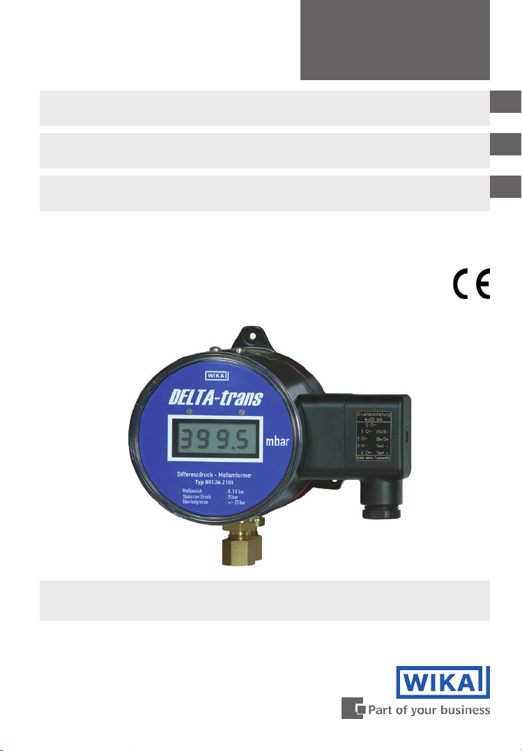
DELTA-trans Model 891.34.2189 with integrated 3½-digit LCD-display
(optional) and compression fitting with ferrule (optional)
Page 2

Operating Instructions Differential Pressure Transmitter
GB
DELTA-trans Model 891.34.2189 Page 3 - 15
Betriebsanleitung Differenzdruck-Messumformer
D
DELTA-trans Typ 891.34.2189 Seite 17 - 29
Mode d‘emploi Transmetteur de pression différentielle
F
DELTA-trans Type 891.34.2189 Page 31 - 43
2279453 08/2009 GB/D/F
Page 3
Contents
Contents
1. Safety instructions 4
2. Operating principle 4
3. Installation instructions 5
4. Installation and commissioning 6
5. Measuring arrangements 7
6. Wiring details 7
7. Version with LCD-display (optional extra) 8
8. Technical data 9
9. Service and maintenance 11
10. Special instructions for integrated pressure equalising valve
or 4-way valve manifold
11. Storage 14
12. Troubleshooting 14
13. Maintenance and servicing 15
GB
12
14. Repairs 15
15. Disposal 15
Warning!
This symbol warns you against actions that can cause
injury to people or damage to the instrument.
2279453 08/2009 GB/D/F
WIKA Operating Instructions Differential Pressure Transmitter DELTA-trans 3
Page 4
1. Safety instructions / 2. Operating principle
1. Safety instructions
GB
The appropriate national safety regulations (i.e. VDE 0100 /
EN 60 079-14 / EN 837-2) must be observed when installing,
commissioning and operating these instruments.
Do not work on the gauge while it is powered
Serious injuries and/or damage can occur should the appropriate regulations
not be observed
Only appropriately qualified personnel should work on these instruments
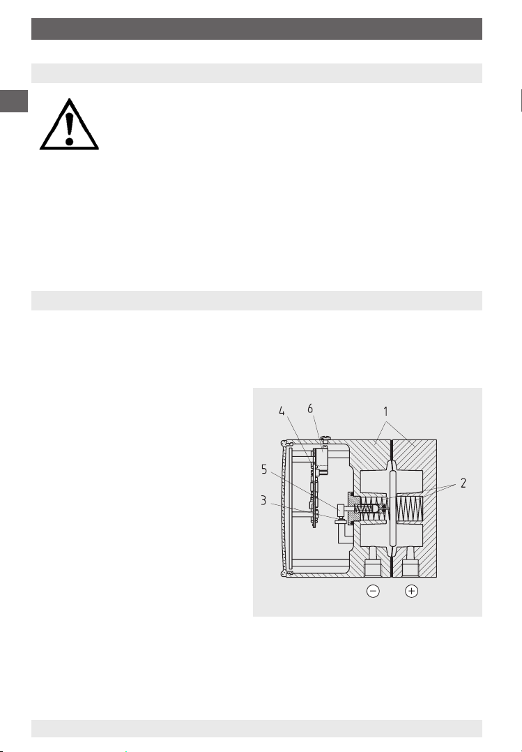
2. Operating principle
The differential pressure transmitter consists mainly of a mechanical measuring system (1) with an elastic pressure element (2), a Hall-effect sensor (3) with
signal processing board (4) and a case with the connections for the electronics.
A magnet (5), rigidly coupled to the
pressure element, influences the
electromagnetic field of the HALLeffect sensor. The resulting signal is
amplified to a standard output signal
via the signal processing board.
2155079.01
For recalibration, zero and span
can be adjusted by means of easily
accessible potentiometers (6).
Pressure entries are identified by the
symbols; j high pressure and i low
pressure
WIKA Operating Instructions Differential Pressure Transmitter DELTA-trans4
2279453 08/2009 GB/D/F
Page 5

3. Installation instructions
3. Installation instructions
Installation arrangement
The pressure transmitter should be installed and operated without exposure
to vibration. It is common practise to install the pressure transmitter fitted to
an isolating device to enable replacement while the system is pressurised
and to isolate the transmitter when reading is not required.
Test connector
Local safety codes such as those for pressure or steam vessels may specify
isolating devices to enable on-site testing of the pressure transmitter.
Mounting provisions
If the pressure system or tailpipe is not rigid enough to accept the weight of
the transmitter, or capable of withstanding any vibrations present, the transmitter should be wall-mounted using a suitable bracket.
Effects of temperature
The operating temperature of the pressure transmitter, resulting from the
effects of the pressure medium, ambient temperatures and possible radiated
heat, must not exceed the temperature range the pressure transmitter is
intended for. Suitably shaped tailpipes or syphons with water filling may be
used to separate the pressure transmitter and its isolating device from hot
pressure media.
Overload protection for pressure elements
Should the measuring media be subject to rapid pressure fluctuations or
there is a possibility of pressure surges, these must not be allowed to act
directly on the pressure element. The effect of any pressure surges must
be restricted, for example, by fitting integral restrictor screws (to reduce the
bore in the pressure connection) or by using adjustable snubber devices.
GB
Pressure test connection
The pressure test connection, with a sufficiently large bore (≥ 6 mm diameter), should be arranged, as far as possible, over a shut-off device, in a
position where the accuracy of reading will not be affected by the flow of the
media being measured. The piping between the pressure test connection
and the pressure transmitter should have an inner diameter large enough to
avoid blockages or delays in pressure transmission. It should also not have
any sharp bends. It is recommended that it is laid with a continuous incline
of approx. 1:15.
2279453 08/2009 GB/D/F
WIKA Operating Instructions Differential Pressure Transmitter DELTA-trans 5
Page 6

Installation instructions / 4. Installation and commissioning
Piping
The piping should be arranged and fitted so that it can withstand the
GB
stresses caused by expansion, vibration and the influence of heat. When
the media is gaseous, a water drain point should be provided at the lowest
point. For liquid pressure media, an air bleed should be provided at the
highest point.
4. Installation and commissioning
Correct sealing of pressure connections should be achieved by means of
suitable sealing rings, sealing washers or WIKA profile seals.
If the pressure transmitter is positioned lower than the pressure test connection, the tailpipe should be thoroughly cleaned prior to fitting the transmitter.
Once the pressure and electrical connections have been made, the transmitters
are ready for immediate use.
No attempt should be made to remove a pressurised transmitter. If the transmitter cannot be otherwise isolated, the pressure system must be fully vented.
Any residual pressure medium contained in the pressure element may be
hazardous or toxic. This should be taken into account when handling and
storing pressure gauges which have been removed.
2279453 08/2009 GB/D/F
6
WIKA Operating Instructions Differential Pressure Transmitter DELTA-trans
Page 7
5. Measuring arrangements / 6. Wiring details
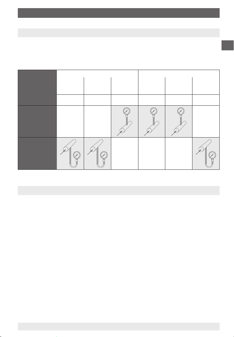
5. Measuring arrangements
Proven measuring arrangements for various types of media.
The recommended arrangements for particular applications are shown below.
Liquid media Gaseous media
Contents of
tailpipe
Typically
Pressure
instrument
higher than
tapping point
Pressure
instrument
lower than
tapping point
Liquid Liquid with
vapour
Condensate Boiling liquid Liquefied gas Dry air Moist air,
Vapour
only
Gas only Wet gas Liquid gas
Flue gas
condensate
Steam
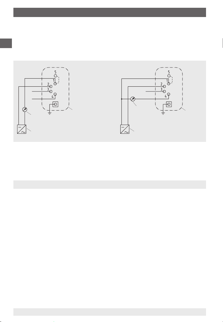
6. Wiring details
Electrical connection of this pressure transmitter is made by cable and connector. Precise wiring diagrams can be seen in the following drawings.
In addition to the wiring details, output signal and required power supply are
given on the rating plate.
GB
Description of terminal designations used:
UB+ Plus terminal for supply voltage
0 V Minus terminal for supply voltage
S+ Plus terminal for output signal
S- Minus terminal for output signal
Test Test terminal
The instruments must be included within the plant’s equipotential bonding
2279453 08/2009 GB/D/F
WIKA Operating Instructions Differential Pressure Transmitter DELTA-trans 7
Page 8
6. Wiring details / 7. Version with LCD-display (optional extra)
Terminal assignment
Terminals 1 and 5 are bridged internally within the connector, so that two terminals are available for the 0 V / S - connection.
GB
4 ... 20 mA 2-wire system 0 ... 20 mA 3-wire system
0 V / S-
UB+ / S+
Test -
Test +
mA
Evaluation
(display/recorder)
Power supply
Connector
housing
0 V / S-
UB+
Test +
S+ / Test-
mA
Evaluation
(display/recorder)
Power suppy
Connector
housing
The transmitter can operate using a non-stabilised supply voltage within the
given limits, so long as the voltage available to the transmitter does not fall
below 10 V, or below 14 V for the LCD-display version.
7. Version with LCD-display (optional)
On integrated LCD-displays, for local pressure read-out, the output signal is 2wire 4 ... 20 mA. For the required power supply for the integrated LCD display,
please refer to Chapter 8, Technical Data.
Limitation on zero point and span adjustment:
If an LCD display is integrated, it must be noted that the zero point and span
adjustment is only to be used for resetting the measuring range. Changes to
the measuring range, made using the zero and span adjustment will not be
shown on the display.
1416 324.03
2279453 08/2009 GB/D/F
WIKA Operating Instructions Differential Pressure Transmitter DELTA-trans8
Page 9

8. Technical data
8. Technical data
Technical data DELTA-trans, Model 891.34.2189
Differential measuring range bar 0 ... 0.16 to 0 ... 25
Working pressure (stat.) max. bar 25
Overload value either side max.
Pressure connections exposed
Pressure media chamber
Press. element comp. spring stainless steel 1.4310 or FD SiCr EN 10 270-2
Press. element separ. diaphr. FPM/FKM fabric back stay (optional NBR)
Links stainless steel 1.4305, FPM/FKM (optional NBR)
Sealing rings FPM/FKM (optional NBR)
Press. equalising valve
(optional)
4-way valve manifold
(optional)
Power supply U
Permissible residual ripple ≤ 0.1 % of span/10 V
Supply voltage effect % ss ≤ 10
Output signal and permissible
max. load R
Effect of load % of span ≤ 0.1
Response time s approx. 1 (optional approx. 50 ms)
Output signal adjustment
Zero point, electrical % of span ± 15
Span, electrical % of span ± 30
Linearity % of span 2.5 (limit point calibration)
(including hysteresis) optional 1.6 (limit point calibration)
Permissible
Medium temperature °C +80 maximum
Ambient temperature °C -10 … +60 (optional LCD-display 0 … 50)
Compensated temp. range °C -10 … +60 (optional LCD-display 0 … 50)
Temperature coefficient in
compensated temp. range
Average TK on zero point ≤ 0.4 % of span/10 K
Average TK on span ≤ 0.4 % of span/10 K
LCD-display (optional)
Voltage load DC V 3.5
Display 3 ½-digit, height 12.7
Ambient temperature °C 0 … 50
Storage temperature °C -10 … +80
Wiring Terminal box (screw terminals up tu 2.5 mm²)
Wiring protection Protected against reverse polarity and overvoltage
EMC (electro-magnetic
compatibility)
Ingress protection IP 54 (optional IP 65) according EN 60 529 / IEC 529
Weight kg approx. 1.3
B
A
bar 25
to medium
exposed to medium
DC V
2 x G ¼ female, bottom, in-line, centre distance 26 mm (optional: other
pressure connections male or female or compression fitting with ferrule for
pipe Ø 6, 8 or 10 mm respectively)
GD-AlSi 12 (Cu) 3.2982, black painted (optional GD-AlSi 12 (Cu) HARD-COAT
surface protection or stainless steel)
stainless steel and FPM/FKM
Cu-alloy or stainless steel, 1x Press. equalising valve, 2 x gauge valve,
1 x valve for purging or air bleeding
10 < UB ≤ 30 (optional LCD-display 14 < UB ≤ 30)
4 … 20 mA, 2-wire system RA ≤ (UB - 10 V) / 0.02 A with RA in Ohm and UB in Volt
0 … 20 mA, 3-wire system RA ≤ (UB - 10 V) / 0.02 A with RA in Ohm and UB in Volt
Interference emission per EN 50 081 - 1 (March 93) and EN 50 081 - 2 (March 94),
Interference immunity per EN 50 082 - 2 (March 95)
GB
2279453 08/2009 GB/D/F
WIKA Operating Instructions Differential Pressure Transmitter DELTA-trans 9
Page 10
8. Technical data
Approval German Lloyd (optional)
GB
Additional or deviating technical data
Pressure ranges bar 0 ... 0.25 to 0 ... 10
Output signal 4 ... 20 mA, 2-wire or 0 ... 20 mA, 3-wire current limit I < 32 mA
Permissible ambient
temperature
EMC (electro-magnetic
compatibility)
ESD kV ± 8 contact discharge IEC 1000-4-2
Electromagnetic fields V/m 10 80 % AM, 1 kHz, 0.01 ... 1000 MHz IEC 1000-4-3
Burst kV ± 2 coupling clamp IEC 1000-4-4
Conducted HF-disturbance V 3 80 % AM, 1 kHz, 0.01 ... 100 MHz IEC 1000-4-6
Surge kV ± 0.5 symmetrically IEC 1000-4-5
Conducted NF-disturbance Veff 3 0.05 ... 10 kHz IEC 945
Vibration test Fc
2 ... 25 Hz, +/- 1.6 mm % < 2.5 error IEC 68-2-6
25 ... 100 Hz, 4 g % < 2.5 error
°C -10 … +70
Interference emission per EN 50 081-1 (March 93) and
EN 50 081-2 (March 94),
interference immunity per EN 50 082-2 (March 95)
kV ± 1 asymmetrically, R i = 42 Ohm
kV ± 1 symmetrically
kV ± 2 asymmetrically, R i = 42 Ohm, with surge
protection only e.g. model MM-DS/xNFE(L), firm Dehn & Söhne or equivalent
10
2279453 08/2009 GB/D/F
WIKA Operating Instructions Differential Pressure Transmitter DELTA-trans
Page 11

9. Service and maintenance
9. Service and maintenance
Always open isolating devices gently, as abrupt opening may generate sudden
pressure surges that may damage the transmitter.
The pressure transmitters require no maintenance or servicing and will give very
long service when handled and operated correctly. It may well be necessary
to check and readjust the zero point periodically. This depends on the working
conditions.
To check zero point
In general, the zero point should be checked and adjusted with the instrument in the unpressurised state.
With differential pressure transmitters the zero point should be checked and
adjusted by opening the pressure equalising valve while under a static load.
The plug screw (NP), found on the top of the case, must be unscrewed to
correct the zero point of the pressure transmitter. The zero point potentiometer
can then be readjusted using a small screwdriver:
turning anticlockwise ⇒ reduces the output signal
turning clockwise ⇒ increases the output signal
To check measuring span
Checking and adjusting the measuring span is a little more complex and has
to be carried out when the pressure transmitter is under pressure, up to the
upper limit of the effective range.
A sufficiently-accurate pressure standard is necessary as a reference.
Only when it is necessary to correct the measuring span should the plug
screw (SP) in the top of the case be unscrewed, and the measuring span
potentiometer can then be readjusted using a small screwdriver:
GB
turning anticlockwise ⇒ reduces the output signal
turning clockwise ⇒ increases the output signal
Once this has been done, the zero point must be checked again and, if necessary, the zero point must be readjusted. This procedure should be repeated
until the zero point and span are calibrated.
2279453 08/2009 GB/D/F
WIKA Operating Instructions Differential Pressure Transmitter DELTA-trans 11
Page 12
9. Service and maintenance / 10. Special instructions ...
Position of potentiometers in the electronics case
GB
SP potentiometer for span
NP potentiometer for zero point
2158991.01
10. Special instructions for integrated pressure equalising valve or
4-way valve manifold
10.1 Integrated pressure equalising valve
For zero point control on working
processes. Offset errors can be adjusted
using the zero point potentiometer (see
Chapter 9. Service and Maintenance)
Principle of operation
When the button is pressed, the
separation between the measuring chambers is released. The pressure
is thus equalised in both chambers, and the differential pressure is zero.
Releasing the button separates the chambers again and the current differential pressure is measured.
12
valve
actuate
Differential pressure drops to zero
WIKA Operating Instructions Differential Pressure Transmitter DELTA-trans
release
Measuring differential
pressure again
2279453 08/2009 GB/D/F
Page 13
10. Special instructions for integrated pressure equalising valve ...
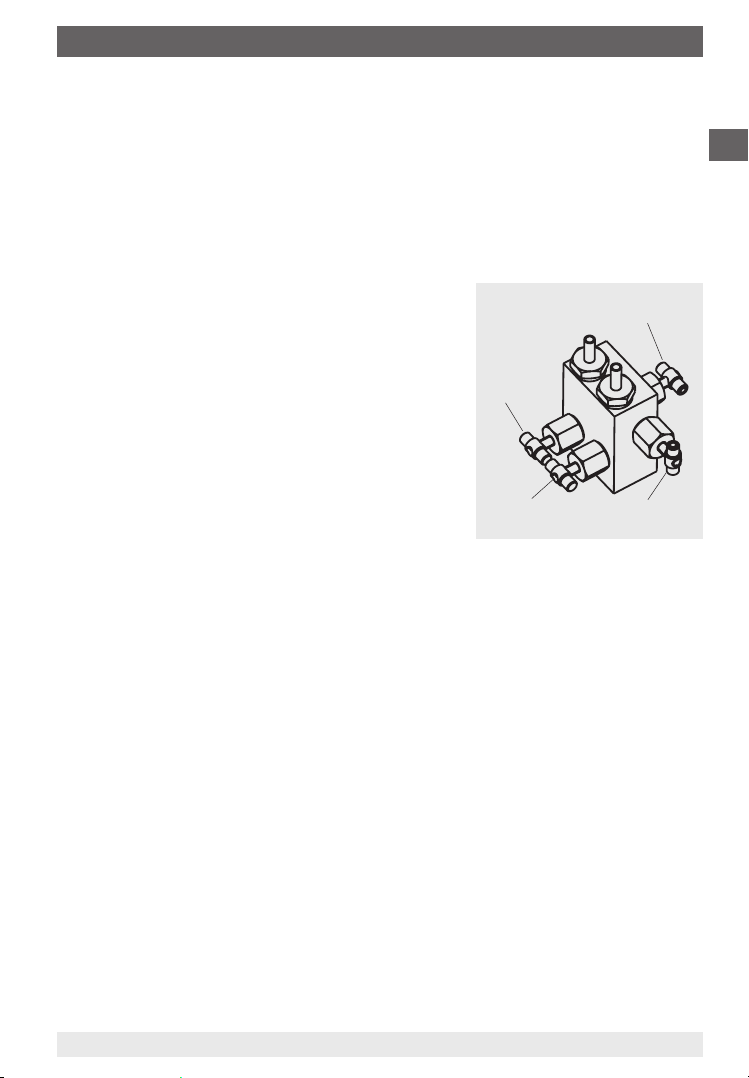
10.2 Four-way valve manifold
Functions
Shut off j- and i-process line for removing the transmitter from working
processes
Pressure equalisation for zero point control on working processes
Process line air bleeding
10.2.1 Handling instructions
Sequence of operations to start measuring
1. Open pressure equalising valve (middle
valve)
2. Open shut-off valve for the minus media
Gauge valve,
high pressure
j-
side
Pressure equalising valve
chamber (i) left valve
3. Open shut-off valve for the plus media
chamber (j) right valve
4. Close pressure equalising valve
Sequence of operations at the end of the
Gauge valve, low
pressure i-side
Valve for purging
or bleeding air
measuring operation (also for partial shutdown of the system)
1. Open pressure equalising valve
2. Close shut-off valve for the minus media chamber (i)
3. Close shut-off valve for the plus media chamber (j)
Sequence of operations to remove the transmitter during working processes
1. Open pressure equalising valve
2. Close shut-off valve for the minus media chamber (i)
3. Close shut-off valve for the plus media chamber (j)
4. Open valve for purging or air bleeding
GB
2279453 08/2009 GB/D/F
WIKA Operating Instructions Differential Pressure Transmitter DELTA-trans 13
Page 14

11. Storage / 12. Troubleshooting
11. Storage
GB
Before installation, in order to prevent damage to the transmitters, the following
points should be observed:
The pressure transmitter should remain in its original packing until installation.
After taking out the transmitter (e.g. for tests), reuse the original packaging
material.
The storage temperature should not be less than -20 °C or more than +60 °C.
Transmitters should be protected against dust and humidity.
12. Troubleshooting
Defect Possible reason Remedy
No signal output Failure of power supply or wiring
Steady signal, despite pressure
changes
Steady and excessively high
signal, despite pressure
changes
Full span reading too low Supply voltage too low Adjust supply voltage
Zero signal too low Zero adjustment made incor-
Zero signal too high Zero adjustment made incor-
Non-linear signal output despite
correct zero adjustment
14
WIKA Operating Instructions Differential Pressure Transmitter DELTA-trans
interrupted
Transmitter miswired Check wiring; if necessary
No pressure Check tailpipes
Electronic defect through incor-
rect supply voltage or external
voltage
Pressure entry blocked Check tailpipes and pressure
Electronic defect through incorrect supply voltage or external
voltage
Transmitter failure through
overpressurisation
Electronic defect through incorrect supply voltage or external
voltage
Load impedance too high Consider permissible max. load
Span adjustment made incor-
rectly
rectly
rectly
Transmitter over-pressurised Return transmitter to manufac-
Transmitter over-pressurised Return transmitter to manufac-
Check power supply and wiring;
replace defective components
rectify it
Return transmitter to manufacturer for repair
entry bore, if necessary clean it
carefully
Return transmitter to manufacturer for repair
Return transmitter to manufacturer for repair
Return transmitter to manufacturer for repair
Re-calibrate transmitter
Re-calibrate transmitter
Re-calibrate transmitter
turer for repair
turer for repair
2279453 08/2009 GB/D/F
Page 15

13. Maintenance and servicing/cleaning ... 15. Disposal
13. Maintenance and servicing/cleaning
The instruments require no maintenance or servicing and will give very long
service when handled and operated properly.
The indicator and switching function should be checked once or twice every
12 months. The instrument must be disconnected from the process before
being checked using pressure testing equipment.
The instruments should be cleaned with a damp cloth, moistened with soap
solution. Ensure that all the parts are dry before the power is switched on again.
Any residual pressure medium contained in the pressure element may be
hazardous or toxic. This should be taken into account when handling and
storing pressure gauges which have been removed.
14. Repairs
Repairs are only to be carried out by the manufacturer or appropriately trained
personnel.
For further details see the Data Sheet for the respective basic gauge PV 17.18.
15. Disposal
Dispose of instrument components and packaging materials in accordance
with the respective waste treatment and disposal regulations of the region or
country to which the instrument is supplied.
GB
2279453 08/2009 GB/D/F
WIKA Operating Instructions Differential Pressure Transmitter DELTA-trans 15
Page 16

GB
16
2279453 08/2009 GB/D/F
WIKA Operating Instructions Differential Pressure Transmitter DELTA-trans
Page 17

Inhalt
Inhalt
1. Sicherheitshinweise 18
2. Funktionsprinzip 18
3. Montagehinweise 19
4. Montage und Inbetriebnahme 20
5 Messanordnung 21
6. Elektrischer Anschluss 21
7. Ausführung mit LCD-Anzeige (Option) 22
8. Technische Daten 23
9. Bedienung und Wartung 25
10. Besonderheiten bei integriertem Druckausgleichsventi oder
Vierfach-Ventilblock
11. Lagerung 28
12. Maßnahmen bei Störungen 28
13. Wartung und Reinigung 29
D
26
14. Reparaturen 29
15. Entsorgung 29
Warnung!
Dieses Symbol warnt Sie vor Handlungen, die Schäden an
Personen oder am Gerät verursachen können.
2279453 08/2009 GB/D/F
WIKA Betriebsanleitung Differenzdruck-Messumformer DELTA-trans 17
Page 18

1. Sicherheitshinweise / 2. Funktionsprinzip
1. Sicherheitshinweise
Beachten Sie unbedingt bei Montage, Inbetriebnahme und
Betrieb dieser Geräte die entsprechenden nationalen Sicher
heitsvorschriften (z. B. VDE 0100 / EN 60 079-14 / EN 837-2).
D
Alle Arbeiten dürfen nur im spannungslosen Zustand erfolgen
Bei Nichtbeachten der entsprechenden Vorschriften können schwere Körper-
verletzungen und / oder Sachschäden auftreten
Nur entsprechend qualifiziertes Personal darf an diesen Geräten arbeiten
2. Funktionsprinzip
Der Differenzdruck-Messumformer besteht im Wesentlichen aus den Funktionsgruppen mechanisches Messsystem (1) mit federelastischem Messglied
(2), magnetfeldabhängiger Sensor (3) mit Signalverarbeitungsplatine (4) und
Gehäuse mit den Anschlussteilen für die Elektronik.
Ein mit dem Messglied fest gekoppelter Magnet (5) beeinflusst das
elektromagnetische Feld des HALLSensors.
Das dabei entstehende Signal wird
durch die Signalverarbeitungsplatine
in ein normiertes Stromausgangssignal verstärkt.
2155079.01
Zur Nachkalibrierung können
Nullpunkt und Spanne über leicht
zugängliche Potentiometer (6) eingestellt werden.
Montage nach angebrachten
Symbolen, j hoher Druck und i
niedriger Druck
18
WIKA Betriebsanleitung Differenzdruck-Messumformer DELTA-trans
2279453 08/2009 GB/D/F
Page 19

3. Montagehinweise
3. Montagehinweise
Montageanordnung
Der Druckmessumformer muss erschütterungsfrei befestigt und betrieben
werden. Es empfiehlt sich, zwischen Druckentnahmestelle und Druckmessumformer eine Absperrvorrichtung zwischenzuschalten, die einen
Austausch des Messgerätes und eine Nullpunktkontrolle bei laufender
Anlage ermöglicht.
Prüfanschluss
Bei bestimmten Anwendungsfällen (z. B. Dampfkessel) müssen die Absperrarmaturen einen Prüfanschluss besitzen, damit der Druckmessumformer
ohne Ausbau überprüft werden kann.
Messgerätebefestigung
Ist die Leitung zum Druckmessumformer für eine erschütterungsfreie Anbringung nicht stabil genug, so ist die Befestigung über die Befestigungslaschen
zur Wandmontage vorzunehmen.
Temperaturbelastung
Die Anbringung des Druckmessumformers ist so auszuführen, dass die
zulässigen Betriebstemperaturen (Umgebung, Messstoff), auch unter
Berücksichtigung des Einflusses von Konvektion und Wärmestrahlung,
weder unter noch überschritten werden. Druckmessumformer und gegebenenfalls angebaute Absperrarmaturen sind z. B. durch ausreichend lange
Messleitungen zu schützen. Der Temperatureinfluss auf die Messgenauigkeit
ist zu beachten.
D
Schutz der Messglieder vor Überlastung
Unterliegt der Messstoff schnellen Druckänderungen oder ist mit Druckstößen zu rechnen, so dürfen diese nicht direkt auf das Messglied einwirken.
Die Druckstöße müssen in ihrer Wirkung gedämpft werden, z. B. durch
Einbau einer Drosselstrecke (Verringerung des Querschnittes im Druckkanal)
oder durch Vorschaltung einer einstellbaren Drosselvorrichtung.
Druckentnahmestutzen
Der Druckentnahmestutzen soll mit einer genügend großen Bohrung (≥ 6 mm)
möglichst über ein Absperrorgan so angeordnet werden, dass die Druckentnahme nicht durch eine Strömung des Messstoffes verfälscht wird. Die Messleitung zwischen Druckentnahmestutzen und Druckmessumformer soll zur
Vermeidung von Verstopfung und Verzögerungen bei der Druckübertragung
einen genügend großen Innendurchmesser besitzen und ohne scharfe
Krümmung sein. Ihre Verlegung mit einer stetigen Neigung von ca. 1:15 ist zu
empfehlen.
2279453 08/2009 GB/D/F
WIKA Betriebsanleitung Differenzdruck-Messumformer DELTA-trans 19
Page 20

3. Montagehinweise / 4. Montage und Inbetriebnahme
Messleitung
Die Messleitung ist so auszuführen und zu montieren, dass sie die auftretenden Belastungen durch Dehnung, Schwingung und Wärmeeinwirkung
aufnehmen kann. Bei Gasen als Messstoff ist an der tiefsten Stelle eine
Entwässerung, bei flüssigen Messstoffen an der höchsten Stelle eine Entlüftung vorzusehen.
D
4. Montage und Inbetriebnahme
Zur Abdichtung der Anschlüsse sind Flachdichtungen, Dichtlinsen oder WIKAProfildichtungen einzusetzen.
Ist der Druckmessumformer tiefer als der Druckentnahmestutzen angeordnet,
dann muss die Messleitung vor dem Anschließen gut durchgespült werden, um
Fremdkörper zu beseitigen.
Nach Herstellen der Druckverbindung und der elektrischen Anschlüsse sind die
Druckmessumformer sofort betriebsbereit.
Vor dem Ausbau des Druckmessumformers ist das Messglied drucklos zu
machen. Gegebenenfalls muss die Messleitung entspannt werden.
Messstoffreste in ausgebauten Druckmessumformern können zur Gefährdung
von Menschen, Umwelt und Einrichtung führen. Ausreichende Vorsichtsmaßnahmen sind zu ergreifen.
2279453 08/2009 GB/D/F
WIKA Betriebsanleitung Differenzdruck-Messumformer DELTA-trans20
Page 21

5. Messanordnungen / 6. Elektrischer Anschluss
5. Messanordnungen
Bewährte Messanordnungen für verschiedene Messstoffarten.
Die zur Anwendung besonders empfohlenen Anordnungen sind nachfolgend
dargestellt.
flüssige Messstoffe gasförmige Messstoffe
Füllung der
Messleitung
Beispiele
Druckmessgerät
oberhalb des
Entnahmestutzens
Druckmessgerät
unterhalb des
Entnahmestutzens
flüssig zum Teil
Kondensat siedende
ausgasend
Flüssigkeiten
vollständig
verdampft
„Flüssiggase“ trockene Luft feuchte Luft,
gasförmig z. T. kon-
densiert
(feucht)
Rauchgase
vollständig
kondensiert
Wasserdampf
6. Elektrischer Anschluss
D
Der elektrische Anschluss der Druckmessumformer wird über Kabeldose und
Kabel hergestellt.
Die genauen Anschlussbelegungen können den nachfolgenden Zeichnungen
entnommen werden. Zusätzlich sind Anschlussbelegung, Ausgangssignal und
erforderliche Hilfsenergie auf dem Typenschild vermerkt.
Bedeutung der verwendeten Klemmenbezeichnungen:
UB+ Plusklemme der Versorgungsspannung
0 V Minusklemme der Versorgungsspannung
S+ Plusklemme des Ausgangssignals
S- Minusklemme des Ausgangssignals
Test Prüfklemmen
Die Geräte sind in den Potenzialausgleich der Anlage mit einzubeziehen.
2279453 08/2009 GB/D/F
WIKA Betriebsanleitung Differenzdruck-Messumformer DELTA-trans 21
Page 22

6. Elektrischer Anschluss / 7. Ausführung mit LCD-Anzeige
Belegung der Anschlussklemmen
Die Klemmen 1 und 5 sind in der Kabeldose intern gebrückt. Dadurch stehen
für den Anschluss von 0 V / S- zwei Klemmen zur Verfügung.
4 … 20 mA Zweileitersystem 0 … 20 mA Dreileitersystem
D
0 V / S-
UB+ / S+
Test -
Test +
mA
Auswertung
(Anzeige, Schreiber)
Hilfsenergie
Kabeldose
0 V / S-
UB+
S+ / Test-
mA
Auswertung
(Anzeige,
Schreiber)
Hilfsenergie
Test +
Kabeldose
Als Hilfsenergie genügt eine unstabilisierte Gleichspannung im Bereich der
angegebenen Grenzen. Es ist darauf zu achten, dass die angelegte Versorgungsspannung um den Betrag höher ist als die maximal erforderliche
Spannung, die an den externen Anzeige- und Auswertegeräten abfällt, d. h.
dass die am Druckmessumformer anliegende Spannung nicht unter 10 V, bei
Ausführung mit LCD-Anzeige nicht unter 14 V abfällt.
7. Ausführung mit LCD-Anzeige (Option)
Bei werksseitig integrierten LCD-Anzeigen zur direkten Druckablesung ist
das Ausgangssignal 4 ... 20 mA / Zweileiter. Die erforderliche Hilfsenergie bei
eingebauter LCD-Anzeige entnehmen Sie bitte den technischen Daten unter
Punkt 8.
1416 324.03
Einschränkung bei Nullpunkt- bzw. Spanneverstellung:
Bei eingebauter LCD-Anzeige ist zubeachten, dass die Nullpunkt- und Spanneverstellmöglichkeit nur zur Nachjustage auf den Messbereich genutzt werden
sollte.
Die Anzeige berücksichtigt keine vom Anwender mittels der Nullpunkt- und
Spanneverstellung vorgenommene Messbereichsveränderung.
22
WIKA Betriebsanleitung Differenzdruck-Messumformer DELTA-trans
2279453 08/2009 GB/D/F
Page 23

8. Technische Daten
8. Technische Daten
Technische Daten DELTA-trans, Typ 891.34.2189
Differenzdruckmessbereich bar 0 ... 0,16 bis 0 ... 25
max. Betriebsdruck (stat.) bar 25
überdruckbelastbar ein-, beid-
u. wechselseitig max.
Druckanschlüsse
Messstoffkammer
Messglied Druckfeder CrNi-Stahl 1.4310 oder FD SiCr EN 10 270-2
Messglied Trennmembran FPM/FKM gewebeverstärkt (Option: NBR)
Übertragungsteile CrNi-Stahl 1.4305, FPM/FKM (Option: NBR)
Dichtungen FPM/FKM (Option: NBR)
Druckausgleichsventil (Option) CrNi-Stahl, Dichtung FPM/FKM
4-fach Ventilblock (Option) 1x Druckausgleichsventil, 2x Absperrventil, 1x Spül- und Entlüftungsven-
Hilfsenergie U
Einfluss der Hilfsenergie ≤ 0,1 % d. Spanne/10 V
zulässige Restwelligkeit % ss ≤ 10
Ausgangssignal und
zulässige max. Bürde R
Bürdeneinfluss % d. Spanne ≤ 0,1
Einstellzeit s ca. 1 (ca. 0,05 Option)
Einstellbarkeit
Kennlinienabweichung
(einschließlich Hysterese)
zulässige
Kompensierter Temp.-bereich °C -10 … +60 (bei Option LCD-Anzeige 0 … 50)
Temperaturkoeffizienten im
kom-pensierten Temperaturbereich
LCD Anzeige (Option)
Elektrischer Anschluss Kabeldose (Schraubklemmen bis 2,5 mm²)
Elektrische Schutzarten Verpolungs- und Überspannungsschutz
EMV (elektromagnetische
Verträglichkeit)
Schutzart IP54 (Option: IP65) nach EN 60 529 / IEC 529
Masse kg ca. 1,3
2279453 08/2009 GB/D/F
B
Nullpunkt, elektrisch % d. Spanne ± 15
Spanne, elektrisch % d. Spanne ± 30
Messstofftemperatur °C max. + 80
Umgebungstemperatur °C -10 … +60 (bei Option LCD-Anzeige 0 … 50)
mittlerer TK des Nullpunktes ≤ 0,4 % d. Spanne/10 K
mittlerer TK der Spanne ≤ 0,4 % d. Spanne/10 K
Spannungslast DC V 3,5
Anzeige 3½-stellig, 12,7 mm hoch
Betriebstemperatur °C 0 … 50
Lagertemperatur °C -10 … +80
WIKA Betriebsanleitung Differenzdruck-Messumformer DELTA-trans 23
bar
messstoffberührt
DC V 10 < UB ≤ 30 (bei Option LCD-Anzeige 14 < UB ≤ 30)
A
% d. Spanne 2,5 (Grenzpunkteinstellung)
25
2 x G ¼ lnnengewinde, unten, hintereinander, Achsabstand 26 mm
(Option: andere Druckanschlüsse für Innen- und Außengewinde bzw.
Schneid- oder Klemmringverschraubungen für Rohrdurchmesser 6, 8
und 10 mm
GD-AlSi 12 (Cu) 3.2982, schwarz lackiert
(Option GD-AlSi 12 (Cu) HART-COAT-Oberflächenschutz oder CrNi-Stahl)
messstoffberührt
til Kupferlegierung oder CrNi-Stahl
4 … 20 mA, Zweileiter RA ≤ (UB - 10 V) / 0,02 A mit RA in Ohm und UB in Volt
0 … 20 mA, Dreileiter RA ≤ (UB - 10 V) / 0,02 A mit RA in Ohm und UB in Volt
Option: 1,6 (Grenzpunkteinstellung)
Störemission nach EN 50 081 - 1 (März 93) und EN 50 081 - 2 (März 94),
Störfestigkeit nach EN 50 082 - 2 (März 95)
D
Page 24

8. Technische Daten
Zulassung Germanischer Lloyd (Option)
D
Ergänzende/abweichende technische Daten
Messbereiche bar 0 ... 0,25 bis 0 ... 10
Ausgangssignal 4 ... 20 mA, Zweileiter oder 0 ... 20 mA, Dreileiter
zulässige
Umgebungstemperatur °C -10 … +70
EMV
(elektromagnetische
Verträglichkeit)
ESD kV ± 8 Kontaktentladung IEC 1000-4-2
elektromagnetische Felder V/m 10 80 % AM, 1 kHz, 0,01 ... 1000 MHz IEC 1000-4-3
Burst kV ± 2 Koppelzange IEC 1000-4-4
leitungsgebundene
HF- Störungen
Surge kV ± 0,5 symmetrisch IEC 1000-4-5
leitungsgebundene NFStörungen
Vibration Prüfung Fc
2 ... 25 Hz, +/- 1,6 mm % < 2,5 Fehler IEC 68-2-6
25 ... 100 Hz, 4 g % < 2,5 Fehler
Strombegrenzung I < 32 mA
Störemission nach EN 50 081-1 (März 93) und
Störfestigkeit nach EN 50 082-2 (März 95)
V 3 80 % AM, 1 kHz, 0,01 ... 100 MHz IEC 1000-4-6
kV ± 1 asymmetrisch, R i = 42 Ohm
kV ± 1 symmetrisch
kV ± 2 asymmetrisch, R i = 42 Ohm, nur mit
V
eff
Überspannungsbegrenzer z. B. MMDS/x-NFE(L), Firma Dehn & Söhne, oder
gleichwertig
3 0,05 ... 10 kHz IEC 945
EN 50 081-2 (März 94),
2279453 08/2009 GB/D/F
WIKA Betriebsanleitung Differenzdruck-Messumformer DELTA-trans24
Page 25

9. Bedienung und Wartung
9. Bedienung und Wartung
Absperreinrichtungen dürfen zur Vermeidung von Druckstößen nur langsam
geöffnet werden.
Die Druckmessumformer sind wartungsfrei und zeichnen sich bei sachgemäßer
Behandlung und Bedienung durch eine hohe Lebensdauer aus. Durch mechanische Belastung je nach Einsatzbedingungen kann es notwendig werden, dass
der Nullpunkt und die Messspanne überprüft und nachjustiert werden müssen:
Nullpunktprüfung
Im Allgemeinen erfolgt die Überprüfung und Einstellung des Nullpunktes im
drucklosen Zustand. Bei Differenzdruck-Messumformern sollte die Überprüfung und Einstellung des Nullpunktes durch Öffnen des Druckausgleichsventiles unter statischer Last erfolgen.
Für die Nullpunktkorrektur des Druckmessumformers ist die Verschlussschraube (NP) auf der Gehäuseoberseite herauszudrehen und mit einem kleinen
Schraubendreher lässt sich daraufhin an einem Potentiometer der Nullpunkt
nachjustieren:
linksdrehen ⇒ Ausgangssignal wird kleiner
rechtsdrehen ⇒ Ausgangssignal wird größer
Spannenüberprüfung
Die Überprüfung und Justage der Messspanne ist aufwendiger und darf nur
erfolgen, wenn der Druckmessumformer bis zum Messbereichsendwert mit
Druck beaufschlagt ist. Hierzu ist ein ausreichend genaues Drucknormal als
Referenz erforderlich. Nur wenn eine Korrektur der Messspanne notwendig
ist, sollte die Verschlussschraube (SP) auf der Gehäuseoberseite gelöst
werden und mit einem kleinen Schraubendreher an dem Potentiometer die
Messspanne nachjustiert werden:
D
linksdrehen ⇒ Ausgangssignal wird kleiner
rechtsdrehen ⇒ Ausgangssignal wird größer
Anschließend muss auch die Nullpunktüberprüfung wiederholt werden und
gegebenenfalls auch der Nullpunkt nachgeregelt werden. Dieser Vorgang ist so
lange zu wiederholen, bis Nullpunkt und Spanne kalibriert sind.
2279453 08/2009 GB/D/F
WIKA Betriebsanleitung Differenzdruck-Messumformer DELTA-trans 25
Page 26

9. Bedienung und Wartung / 10. Besonderheiten ...
Lage der Potentiometer am Elektronikgehäuse
SP Potentiometer für Spanne
NP Potentiometer für Nullpunkt
D
2158991.01
10. Besonderheiten bei integriertem Druckausgleichsventil oder
Vierfach-Ventilblock
10.1 Integriertes Druckausgleichsventil
Zur Nullpunktkontrolle während des
laufenden Prozesses.
Nullpunktabweichungen können mittels
Potentiometer für Nullpunkt (siehe Punkt
9. Bedienung und Wartung) korrigiert
werden.
Funktionsprinzip
Durch Betätigen des Druckknopfes wird die Trennung der Messstoffkammern aufgehoben. In beiden Kammern liegt nun der gleiche Druck an, d. h.
der Differenzdruck ist Null. Nach dem Loslassen des Druckausgleichsventils
werden die Messstoffkammern wieder getrennt und der aktuelle Differenzdruck wird wieder gemessen.
26
Ventil
betätigt
Differenzdruck
gleich Null
WIKA Betriebsanleitung Differenzdruck-Messumformer DELTA-trans
Losgelassen
Differenzdruck
wird wieder gemessen
2279453 08/2009 GB/D/F
Page 27

10. Besonderheiten bei integriertem Druckausgleichsventil ...
10.2 Vierfach-Ventilblock
Funktionen
Absperrung der j- und i-Prozessleitung zur Demontage des Messge-
rätes bei laufenden Prozess
Druckausgleich zur Nullpunktkontrolle bei laufenden Prozess
Entlüftung der Messleitungen
10.2.1 Angaben zum Handling
Arbeitsgangfolge zum Messanfang
1. Druckausgleichsventil (mittlere Ventilspindel)
öffnen
2. Absperrventil der Minus-Messstoffkammer
(i, rechtes Ventil) öffnen
3. Absperrventil der Plus-Messstoffkammer
(j, linkes Ventil) öffnen
4. Druckausgleichsventil schließen
Arbeitsgangfolge zu Messende
(auch zeitweise Stilllegung)
1. Druckausgleichsventil öffnen
2. Absperrventil der Minus-Messstoffkammer
(i) schließen
3. Absperrventil der Plus-Messstoffkammer
(j) schließen
Absperrventil
j-Seite
Absperrventil
i-Seite
Druckausgleichsventil
Entlüftungsventil
D
Arbeitsgangfolge zur Demontage des Messgerätes bei laufenden Prozess
1. Druckausgleichsventil öffnen
2. Absperrventil der Minus-Messstoffkammer (i) schließen
3. Absperrventil der Plus-Messstoffkammer (j) schließen
4. Entlüftungsventil öffnen
2279453 08/2009 GB/D/F
WIKA Betriebsanleitung Differenzdruck-Messumformer DELTA-trans 27
Page 28

11. Lagerung / 12. Maßnahmen bei Störungen
11. Lagerung
Für die Lagerung der Druckmessumformer bis zur Montage sind, um Schäden
zu vermeiden, folgende Punkte zu beachten:
D
Druckmessumformer in der Originalverpackung belassen.
Nach einer eventuellen Entnahme der Messgeräte (z. B. für Prüfungen) ist die
Originalverpackung wieder zu verwenden.
Lagertemperaturbereich -20 °C ... +60 °C
Messgeräte vor Feuchtigkeit und Staub schützen.
12. Maßnahmen bei Störungen
Störung mögliche Ursache Maßnahme
Kein Ausgangssignal keine Versorgungsspannung
gleichbleibendes Ausgangssignal bei Druckänderung
zu hohes, bei Druckänderung
gleichbleibendes Ausgangssignal
Signalspanne zu klein Versorgungsspannung zu
Nullpunktsignal zu klein Nullpunkt-Potentiometer
Nullpunktsignal zu groß Nullpunkt-Potentiometer
Signalkennlinie unlinear nach
Nullpunktkorrektur
oder Leitungsbruch
Messumformer falsch
angeschlossen
kein Eingansdruck Druckzuführung überprüfen
Elektronik defekt durch zu hohe
Versorgungsspannung oder
durch Fremdspannung
Eingangskanal verstopft Eingangskanal bzw. Drossel-
Elektronik defekt durch zu hohe
Versorgungsspannung oder
durch Fremdspannung
Messumformer defekt nach
mechanischer Überbelastung
Elektronik defekt durch zu hohe
Versorgungsspannung oder
durch Fremdspannung
niedrig
Bürde zu hoch max. zulässige Bürde beachten
Spannen-Potentiometer verstellt Messumformer neu justieren
verstellt
verstellt
mechanische Überlastung Messumformer zur Instandset-
mechanische Überlastung Messumformer zur Instandset-
WIKA Betriebsanleitung Differenzdruck-Messumformer DELTA-trans28
Spannungsversorgung und
Leitungen überprüfen. ggf.
defekte Teile austauschen
Anschlüsse überprüfen;
Anschlüsse ggf. korrigieren
Messumformer zur Instandsetzung an Hersteller zurück
schraube reinigen
Messumformer zur Instandset-
zung an Hersteller zurück
Messumformer zur Instandsetzung an Hersteller zurück
Messumformer zur Instandsetzung an Hersteller zurück
Versorgungsspannung korrigieren
Messumformer neu justieren
Messumformer neu justieren
zung an Hersteller
zung an Hersteller
2279453 08/2009 GB/D/F
Page 29

13. Wartung und Reinigung ... 15. Entsorgung
13. Wartung und Reinigung
Die Geräte sind wartungsfrei und zeichnen sich bei sachgemäßer Behandlung
und Bedienung durch eine hohe Lebensdauer aus.
Eine Überprüfung der Anzeige und der Schaltfunktion sollte etwa 1 bis 2 mal
pro Jahr erfolgen. Dazu ist das Gerät vom Prozess zu trennen und mit einer
Druckprüfvorrichtung zu kontrollieren.
Reinigen der Geräte mit einem (in Seifenlauge) angefeuchteten Tuch.
Vor Wiedereinschalten des Stromes ist sicherzustellen, dass alle Teile
abgetrocknet sind.
Messstoffreste in ausgebauten Druckmessgeräten können zu Gefährdung von
Menschen, Umwelt und Einrichtungen führen. Ausreichende Vorsichtsmaßnahmen sind zu ergreifen.
14. Reparaturen
Reparaturen sind ausschließlich vom Hersteller oder entsprechend geschultem
Personal durchzuführen.
Weitere technische Daten bitte dem Datenblatt PV 17.18 entnehmen.
15. Entsorgung
D
Entsorgen Sie Gerätekomponenten und Verpackungsmaterialien entsprechend
den einschlägigen landesspezifischen Abfallbehandlungs- und Entsorgungsvorschriften des Anliefergebietes.
2279453 08/2009 GB/D/F
WIKA Betriebsanleitung Differenzdruck-Messumformer DELTA-trans 29
Page 30

D
2279453 08/2009 GB/D/F
WIKA Betriebsanleitung Differenzdruck-Messumformer DELTA-trans30
Page 31

Sommaire
Sommaire
1. Consignes de sécurité 32
2. Principe de fonctionnement 32
3. Instructions de montage 33
4. Installation et mise en service 34
5 Installation sur le point de mesure 35
6. Branchement électrique 35
7. Exécution avec afficheur LCD (option) 36
8. Caractéristiques techniques 37
9. Exploitation et entretien 39
10. Particularités avec robinet d'équilibrage de pression ou
manifold 4 voies
11. Stockage 42
12. Mesures à prendre en cas de pannes 42
13. Entretien / Nettoyage 43
14. Réparations 43
15. Mise au rebus 43
40
F
Attention!
Ce symbôle vous prévient contre les actions qui peuvent
causer des blessures aux utilisateurs ou endommager les
instruments.
2279453 08/2009 GB/D/F
WIKA Mode d‘emploi Transmetteur de pression différentielle DELTA-trans 31
Page 32

1. Consignes de sécurité / 2. Principe de fonctionnement
1. Consignes de sécurité
Les prescriptions de sécurité nationales en vigueur (par
exemple VDE 0100 / EN 60 079-14 / EN 837-2) doivent absolument être respectées lors du montage, de la mise en service et
de l‘utilisation des instruments ici présentés.
Toutes les interventions doivent être effectuées hors tension
F
Le non-respect des instructions correspondantes est susceptible d‘entraîner
des risques de blessure et/ou des dégâts matériels
Seul le personnel habilité et qualifié est autorisé à manipuler les instruments
2. Principe de fonctionnement
Le transmetteur de pression différentielle est essentiellement constitué d'un
système de mesure mécanique (1) avec élément de mesure élastique (2), un
capteur à effet Hall (3) associé à une carte de traitement du signal (4) et un
boîtier de raccordement électrique.
Un aimant (5) couplé à l'élément de
mesure influe sur le champ électromagnétique du capteur à effect Hall.
Le signal en résultant est amplifié par
la carte de traitement de signal pour
devenir signal de sortie normalisé.
2155079.01
Pour le réétalonnage, le zéro et l'étendue de mesure peuvent être réglés au
moyen de potentiomètres facilement
accessibles (6).
Identification des raccords:
j pression et i pression
32
WIKA Mode d‘emploi Transmetteur de pression différentielle DELTA-trans
2279453 08/2009 GB/D/F
Page 33

3. Instructions de montage
3. Instructions de montage
Disposition
Le transmetteur de pression doit être fixé exempt de vibrations mécaniques
et sa position doit permettre une lecture facile. Il est utile de monter entre le
transmetteur de pression et la prise de pression un robinet d'isolement, ce
qui permet, en cas de nécessité et avec l'installation en service, de remplacer le transmetteur de pression ou d'en contrôler le zéro.
Prise de contrôle
Dans certains cas d'application (par exemple dans le cas de chaudières de
vapeur) les organes de fermeture doivent être pourvus d'une prise de contrôle afin de pouvoir contrôler le transmetteur de pression sans démontage.
Fixation des instruments de mesure
Si la tuyauterie recevant le transmetteur de pression n'est pas assez stable
pour garantir une pose sans vibration, la fixation de l'appareil doit être effectuée au moyen des pattes de fixation murale.
Amortissement du système de mesure
S'il est impossible, au moyen d'installations appropriées, d'éviter les vibrations, il faut alors utiliser des appareils à amortissement par remplissage de
liquide.
F
Contraintes thermiques
La position du transmetteur de pression est à choisir en fonction de la
température de service qui ne doit pas être dépassée, en tenant compte
également de l'influence de la conduction et du rayonnement thermique.
Pour ce faire on utilisera des tuyaux-raccord suffisamment longs ou des
syphons placés avant le robinet et le transmetteur de pression. Prendre en
considération l'influence de la température sur la précision de la mesure.
Protection des organes moteur contre les surcharges
Si le milieu de mesure est soumis à des fluctuations rapides de pression ou
s'il faut s'attendre à des coups de bélier, il faut veiller à ce que ces phénomènes n‘exercent aucun impact sur l‘organe moteur de l’appareil. Les effets
des coups de bélier doivent être amortis, par exemple par la mise en place
d‘une vis frein (diminution de la section du canal sous pression) ou par l‘installation en amont de l‘appareil d‘un dispositif d‘amortissement réglable.
2279453 08/2009 GB/D/F
WIKA Mode d‘emploi Transmetteur de pression différentielle DELTA-trans 33
Page 34

3. Instructions de montage / 4. Installation et mise en service
Raccord de la prise de pression
Le raccord de la prise de pression doit être pourvu d'un orifice suffisam-
ment grand ( 6 mm), si possible posséder un robinet d'isolement et être
installé de façon à ce que le débit du fluide ne perturbe pas la mesure. La
tuyauterie entre le raccord de mesure et le transmetteur de pression doit
avoir un diamètre suffisant afin d'en éviter son bouchage ou de provoquer
des retards dans la transmission de la pression. On évitera également des
courbures trop importantes. Il est recommandé d'installer la tuyauterie avec
F
un rapport d'inclinaison de 1:15.
Tuyauterie
La tuyauterie est à concevoir et à installer de telle façon qu'elle supporte les
contraintes dues á des dilatations, vibrations et influences thermiques. Pour
la mesure de gaz, il faut prévoir une purge de condensat au point le plus bas
de l'installation, et pour la mesure de liquides il faut une purge d'air au point
le plus èlevé.
4. Installation et mise en service
Pour l'étanchéité des raccords, il faut utiliser des joints plats, des lentilles
d'étanchéité ou des joints profilés WIKA.
En cas d'installation du transmetteur de pression au-dessous du point de
mesure, il faut nettoyer soigneusement la tuyauterie afin d'éviter que des particules pénètrent à l'intérieur de l'appareil.
Après réalisation du raccord de pression et des branchements électriques, les
transmetteurs sont prêts à fonctionner.
La pression sur le transmetteur de pression doit être à zéro avant de le démonter. Si nécessaire vider la tuyauterie.
Les résidus de fluide se trouvant à l'intérieur des transmetteurs de pression
démontés peuvent présenter des dangers pour les personnes, l'environnement
et les installations. Il faut prendre toutes les précautions nécessaires pour en
assurer la sécurité.
WIKA Mode d‘emploi Transmetteur de pression différentielle DELTA-trans34
2279453 08/2009 GB/D/F
Page 35

5. Installation sur le point de mesure / 6. Branchement électrique
5. Installation sur le point de mesure
Dispositions éprouvées pour les différents types de matériaux.
Les différentes dispositions recommandées pour application sont représentées
ci-après.
fluides liquides fluides gazeux
Remplissage
de la conduite
de mesure
Exemples
Manomètre
au-dessus
du point de
mesure
Manomètre
au-dessous
du point de
mesure
liquides en partie
condensat liquides en
gazeux
ébullition
complètement
évaporés
„gaz liquides“ air sec air humide,
fluide
gazeux
en partie
condensés
(humides)
gaz de
combustion
entièrement
condensé
vapeur d‘eau
6. Branchement électrique
F
Le raccordement électrique des transmetteurs de pression s'effectue à l'aide
d‘un boîtier de raccordement et d’un câble. La disposition exacte des connections est donnée sur les dessins présentés ci-après. En outre, la disposition
des connections, le signal de sortie et l'alimentation auxiliaire nécessaires sont
notés sur la plaque de signalisation de l'appareil.
Signification des différents symboles de borne utilisés:
UB+ Borne positive de la tension d'alimentation
0 V Borne négative de la tension d'alimentation
S+ Borne positive du signal de sortie
S- Borne négative du signal de sortie
Test Bornes de contrôle
Les appareils doivent être intégrés dans la compensation de potentiel du
site.
2279453 08/2009 GB/D/F
WIKA Mode d‘emploi Transmetteur de pression différentielle DELTA-trans 35
Page 36

6. Branchement électrique / 7. Exécution avec afficheur LCD (option)
Détail des connections
Les bornes 1 et 5 sont shuntées à l'intérieur du boîtier de raccordement pour
fournir 2 bornes pour la connexion 0 V / S.
4 … 20 mA 2-fils 0 … 20 mA 3-fils
F
0 V / S-
UB+ / S+
Test -
Test +
mA
Appareil récepteur
(ex: indicateur)
Alimentation
Boîtier de
raccord
0 V / S-
UB+
Test +
S+ / Test-
mA
Appareil
récepteur
(ex: indicateur)
Alimentation
En tant qu'alimentation auxiliaire, une tension continue non-stabilisée dans
les limites indiquées est suffisante. Il est indispensable de veiller à ce que la
tension d'alimentation appliquée présente une valeur supérieure à la tension
maximale requise au droit des appareils d'affichage et d'évaluation externes,
c'est-à-dire que la tension appliquée au droit du transmetteur de pression
ne doit pas être inférieure à 10 V; dans le cas des modèles avec afficheur à
cristaux liquides (LCD), elle ne doit pas être inférieure à 14 V.
7. Exécution avec afficheur LCD (option)
Avec l’afficheur LCD intégré pour indication locale de la pression, le signal de
sortie est de 4 … 20 mA / deux fils. L‘énergie auxiliaire nécessaire à l’afficheur
LCD intégré est indiquée au tableau des caractéristiques techniques, point 8.
Boîtier de
raccord
1416 324.03
Conditions limitatives pour le réglage du point zéro et de l'écart:
Si l‘appareil est équipé d‘un afficheur LCD intégré, il faut tenir compte du fait
que la possibilité de réglage du point zéro et de l‘écart ne doit être utilisée que
pour l‘ajustement sur l‘étendue de mesure. L‘affichage ignore toute modification de l‘étendue de mesure que l‘utilisateur effectuerait par réglage du point
zéro et de l‘écart.
36
WIKA Mode d‘emploi Transmetteur de pression différentielle DELTA-trans
2279453 08/2009 GB/D/F
Page 37

8. Caractéristiques techniques
8. Caractéristiques techniques
Caractéristiques techniques DELTA-trans, Type 891.34.2189
Etendue de mesure bar 0 ... 0,16 à 0 ... 25
Pression de service maxi
(pression statique)
Surcharge admissible bar 25 (de chaque côte)
Raccords en contact
Chambre de mesure
Ressort acier inox 1.4310 (304H) ou FD SiCr EN 10 270-2
Membrane FPM/FKM renforcé par textile (option: NBR)
Pièces de liaison acier inox 1.4305 (303), FPM/FKM (option: NBR)
Joints d'étanchéité FPM/FKM (option: NBR)
Robinet d'équil. de pression acier inox ou FPM/FKM
Manifold 4 voies en option: 1 x rob. équil. pres., 2 x rob. mano., 1 x purge/mise à l'air
Alimentation U
Influence d'alimentation ≤ 0,1
Ondulation résiduelle admis. % ss ≤ 10
Signal de sortie et résis- 4 … 20 mA, 2 fils RA ≤ (UB - 10 V) / 0,02 A avec RA en Ohm et UB en Volt
tance de charge R
Déviation due à la charge % d'échelle ≤ 0,1
Temps du réponse s environ 1 (option: environ 0,05)
Réglage du signal de sortie:
Précision % d'échelle 2,5 (méthode des points extrêmes)
(incluant l'hystérésis) option: 1,6 (méthode des points extrêmes)
Températures autorisées:
Coefficient de température sur
plage compensée:
≤ 0,4
≤ 0,4
Afficheur LCD (option)
Câblage Boîtier presse-étoupe (section des vis jusqu'à 2,5 mm²)
Protection électrique Protégé contre l'inversion de polarité et la surtension
CEM Emission de perturbation selon EN 50 081-1 (Mars 93) et EN 50 081-2
Degré de protection IP 54 (IP 65 en option) (selon EN 60529 / IEC 529)
Poids kg env. 1,3 kgs
B
A
point zéro % d'échelle ± 15
gain % d'échelle ± 30
fluide °C +80 maximum
ambiante °C -10 … +60 (option afficheur LCD 0 ... 50)
plage de tem. Compensée °C -10 … +60 (option afficheur LCD 0 ... 50)
TK coef. de temp. moy. du
pt. zéro
TK coef. de temp. moy. du
gain
chute de tension DC V 3,5
afficheur 3½ digits, hauteur 12,7 mm
température ambiante °C 0 … 50
température de stockage °C -10 … +80
2279453 08/2009 GB/D/F
WIKA Mode d‘emploi Transmetteur de pression différentielle DELTA-trans 37
bar 25
avec le
fluide
DC V 10 < UB ≤ 30 (option afficheur LCD 14 < UB ≤ 30)
2 x G ¼ femelle, en bas, espacement axial 26 mm
(en option: autres raccords filetées mâle ou femelle, raccords pour
tuyaux souples ou rigides Ø 6, 8 ou 10 mm)
alliage d'aluminium peint en noir (en option: alliage d'aluminium avec
revêtement HART-COAT, inox)
en contact avec le fluide
% d'échelle/10 V
0 … 20 mA, 3 fils RA ≤ (UB - 10 V) / 0,02 A avec RA en Ohm et UB en Volt
% d'échelle/10 V
% d'échelle/10 V
(Mars 94), Immunité aux perturbations EN 50 082-2 (Mars 95)
F
Page 38

8. Données techniques
Homologation GL (option)
Données techniques supplémentaires/differentes
Etendue de mesure bar 0 ... 0,25 à 0 ... 10
F
Signal de sortie 4 ... 20 mA, 2 fils ou 0 ... 20 mA, 3 fils
Températures autorisées
ambiante
CEM
Déchargé electro-statique kV ± 8 Décharge aux contacts IEC 1000-4-2
Champ électromagnétique V/m 10 80 % AM, 1 kHz, 0,01 ... 1000 MHz IEC 1000-4-3
Transitoires rapides kV ± 2 Couplage direct IEC 1000-4-4
HF V 3 80 % AM, 1 kHz, 0,01 ... 100 MHz IEC 1000-4-6
Onde hybride kV ± 0,5 symétrique IEC 1000-4-5
leitungsgebundene NFStörungen
Vibration test Fc
2 ... 25 Hz, +/- 1,6 mm % < 2,5 Erreur IEC 68-2-6
25 ... 100 Hz, 4 g % < 2,5 Erreur
Limitation du courant I < 32 mA
°C -10 … +70
Emission de perturbation selon
Immunité aux
perturbations
kV ± 1 asymétrique, R i = 42 Ohm
kV ± 1 symétrique
kV ± 2 asymétrique, R i = 42 Ohm,
V
eff
seulement avec limitateur de tension
par exemple MM-DS/x-NFE(L),
Dehn & Söhne ou identique
3 0,05 ... 10 kHz IEC 945
EN 50 081-1 (Mars 93) et
EN 50 081-2 (Mars 94),
EN 50 082-2 (Mars 95)
38
2279453 08/2009 GB/D/F
WIKA Mode d‘emploi Transmetteur de pression différentielle DELTA-trans
Page 39

9. Exploitation et entretien
9. Exploitation et entretien Homologation GL (option)
Les dispositifs d'ouverture/fermeture ne doivent être ouverts que lentement
pour éviter les coups de bélier.
Les transmetteurs de pression ne nécessitent aucun entretien et sont caractérisés par une grande longévité, sous réserve d'une manipulation et exploitation
correctes.
Contrôle du point zéro
En règle générale, le contrôle et le réglage du point zéro s'effectuent l'appareil hors pression. Dans le cas des transmetteurs de pression différentielle, le
contrôle et le réglage du point zéro doivent s'effectuer en ouvrant la soupape
de compensation de pression sous charge statique.
Pour la correction du point zéro du transmetteur, il faut dévisser la vis de fermeture (NP) qui se trouve sur le dessus du boîtier. Ensuite, le point zéro peut être
réajusté sur un potentiomètre, au moyen d'un petit tournevis:
En tournant vers la gauche ⇒ Signal de sortie diminue
En tournant vers la droite ⇒ Signal de sortie augmente
Contrôle de la plage de mesure
Le contrôle et l'ajustage de la plage de mesure est une opération complexe
qui ne doit être effectuée que si le transmetteur de pression est soumis à
une pression atteignant la valeur maximale de l'étendue de mesure. Dans ce
contexte, une normale de pression suffisamment exacte est nécessaire en
tant que référence.
Dans le cas où une correction de la plage de mesure s'avère nécessaire, il
faut dévisser la vis de fermeture (SP) qui se trouve sur la partie supérieure
du boîtier et réajuster la plage de mesure sur le potentiomètre avec un petit
tournevis:
F
En tournant vers la gauche ⇒ Signal de sortie diminue
En tournant vers la droite ⇒ Signal de sortie augmente
Enuite, il faut également réitérer le contrôle du point zéro et, le cas échéant, le
réajuster. Cette opération est à répéter jusqu'à ce que le point zéro et l'étendue
de mesure soient réétalonnés.
2279453 08/2009 GB/D/F
WIKA Mode d‘emploi Transmetteur de pression différentielle DELTA-trans 39
Page 40

9. Exploitation et entretien / 10. Particularités ...
Position du potentiomètre sur le boîtier électronique
SP Potentiomètre pour gain
NP Potentiomètre pour point zéro
F
2158991.01
10. Particularités avec robinet d'équilibrage de pression ou manifold 4 voies
10.1 Robinet d'équilibrage de pression intégré
Pour le contrôle du point zéro en
fonctionnement. Les écarts du point
zéro peuvent être corrigés au moyen du
potentiomètre pour point zéro (voir point
8: Exploitation et entretien)
Principe de fonctionnement
En appuyant sur le bouton-poussoir,
on ouvre la séparation entre les
chambres du système de mesure. Il y a alors égalisation de la pression
dans chacune des deux chambres, c'est-à-dire que la pression différentielle
est alors égale à zéro. En relâchant la soupape d'équilibre de pression, on
rétablit la séparation entre les chambres et la pression différentielle peut
alors être à nouveau mesurée.
40
Activation de
la soupape
Pression
différentielle = zéro
WIKA Mode d‘emploi Transmetteur de pression différentielle DELTA-trans
Relâchement
de la soupape
La pression différentielle est à nouveau
mesurée
2279453 08/2009 GB/D/F
Page 41

10. Particularités avec robinet d'équilibrage de pression ...
10.2 Manifold 4 voies
Fonctions
Isolement de la conduite du circuit pour démontage de l'appareil de
mesure en cours de fonctionnement
Egalisation de la pression pour contrôle du point zéro en cours de fonction-
nement
Purge de l'air des conduites de mesure
10.2.1 Informations pour la manipulation de l'appareil
Séquence des opérations avant démarrage
des mesures
1. Ouvrir robinet d'équilibrage de pression
(tige de soupape médiane)
2. Ouvrir robinet à pointeau de la chambre
moins du système de mesure (soupape
Robinet à
pointeau
(côté j)
droite, côté moins i)
3. Ouvrir robinet à pointeau de la chambre
plus du système de mesure (soupape
gauche, côté plus j)
4. Fermer robinet d'équilibre de pression
Séquence des opérations avant la fin des
Robinet à pointeau (côté i)
mesures (également en cas de mise hors
service temporaire)
1. Ouvrir robinet d'équilibrage de pression
2. Fermer robinet à pointeau de la chambre moins du système de mesure (i)
3. Fermer robinet à pointeau de la chambre plus du système de mesure (j)
Robinet d'équilibrage de pression
soupape de
vidange d'air
F
Séquence des opérations avant démontage de l'appareil de mesure en
cours de fonctionnement
1. Ouvrir robinet d'équilibrage de pression
2. Fermer robinet à pointeau de la chambre moins du système de mesure (i)
3. Fermer robinet à pointeau de la chambre plus du système de mesure (j)
4. Ouvrir la soupape de purge d'air
2279453 08/2009 GB/D/F
WIKA Mode d‘emploi Transmetteur de pression différentielle DELTA-trans 41
Page 42

11. Stockage / 12. Mesures à prendre en cas de pannes
11. Stockage
Pour stocker les transmetteurs de pression en attendant leur montage, il est
nécessaire - afin d'éviter des dégats - de respecter les points suivants:
Laisser les transmetteurs de pression dans leur emballage d'origine.
Après avoir prélevé un transmetteur de pression (par exemple pour un
contrôle) le réemballer dans son emballage d'origine.
F
Température de stockage -20 °C ... +60 °C
Protéger les appareils de l'humidité et de la poussière.
12. Mesures à prendre en cas de pannes
Panne Cause possible Mesure à prendre
Aucun signal de sortie Aucune tension d'alimentation Rupture
Signal de sortie constant
sous modification de
pression
Signal de sortie trop élevé
et constant sous modification de pression
Plage de signalisation trop
faible
Point zéro trop faible Déréglage du potentiomètre du point
Point zéro trop élevé Déréglage du potentiomètre du point
Courbe caractéristique de
signalisation non-linéaire
après correction du point
zéro
42
de cable
Transmetteur mal branché Contrôler les branchements; le cas
Aucune pression d'entrée Contrôler l'arrivée de pression
Electronique défectueuse, conséquence
d'une tension d'alimentation trop élevée ou
d'une tention d'origine étrangère
Canal d'entrée bouché Nettoyer le canal d'entrée et/ou la vis
Electronique défectueuse, conséquence
d'une tension d'alimentation trop élevée ou
d'une tention d'origine étrangère
Transmetteur défectueux à la suite d'une
surcharge mécanique
Electronique défectueuse, conséquence
d'une tension d'alimentation trop élevée ou
d'une tention d'origine étrangère
Tension d'alimentation trop faible Corriger la tension d'alimentation
Charge ohmique trop élevée Respecter la charge ohmique max. admise
Déréglage du potent. de la plage de
mesure
neutre
neutre
Surcharge mécanique Envoyer le transmetteur au fabricant pour
Surcharge mécanique Envoyer le transmetteur au fabricant pour
WIKA Mode d‘emploi Transmetteur de pression différentielle DELTA-trans
Contrôler l'alimentat. en courant et les
cables; le cas échéant changer les pièces
défectueuses
échéant, corriger les branchements
Envoyer le transmetteur au fabricant pour
réparation
d'étranglement
Envoyer le transmetteur au fabricant pour
réparation
Envoyer le transmetteur au fabricant pour
réparation
Envoyer le transmetteur au fabricant pour
réparation
Réajuster le transmetteur
Réajuster le transmetteur
Réajuster le transmetteur
réparation
réparation
2279453 08/2009 GB/D/F
Page 43

13. Entretien / Nettoyage ... 15. Mise au rebus
13. Entretien / Nettoyage
S‘ils sont manipulés et utilisés correctement, les instruments ne requièrent
aucune maintenance et se distinguent par une longue durée de vie.
Un contrôle de l‘affichage et des fonctions de commande est recommandé 1
à 2 fois/an. Pour le contrôle de l‘afficheur et des fonctions de commande, il
faut isoler l‘appareil du process de mesure et le contrôler avec un dispositif de
contrôle de pression.
L‘appareil se nettoie à l‘aide d‘un chiffon humidifié (avec du savon).
Avant de rebrancher l‘instrument, s‘assurer que toutes les pièces soient
complètement sèches.
Des restes de fluide se trouvant dans les manomètres démontés peuvent provoquer une mise en danger de personnes, de l‘environnement et de
l‘équipement. Des précautions adéquates sont à prendre.
14. Réparations
Toute réparation doit être exclusivement confiée au fabricant à du personnel
qualifié correspondant.
Pour autres données, se reporter à la fiche technique de l‘instrument PV 17.18)
F
15. Mise au rebus
Mettez les composants des appareils et les emballages au rebus en respectant
les prescriptions nationales pour le traitement et la mise au rebus des régions
ou pays de livraison.
2279453 08/2009 GB/D/F
WIKA Mode d‘emploi Transmetteur de pression différentielle DELTA-trans 43
Page 44

Technical alteration rights reserved.
Technische Änderungen vorbehalten.
Sous réserve de modifications techniques.
WIKA Alexander Wiegand SE & Co. KG
Alexander-Wiegand-Straße 30
63911 Klingenberg • Germany
Tel. (+49) 9372/132-0
Fax (+49) 9372/132-406
E-Mail info@wika.de
www.wika.de
44
2279453.02 08/2009 GB/D/F
 Loading...