

Page 1
Operating Instructions
Betriebsanleitung
Mode d'emploi
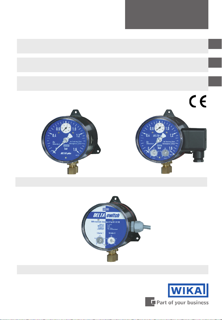
Differential pressure gauges
Model 702.01.100, 702.02.100 and 851.02.100
Differenzdruckmessgeräte
Typ 702.01.100, 702.02.100 und 851.02.100
Manomètres pour pression différentielle
Type 702.01.100, 702.02.100 et 851.02.100
su st
Model 702.01.100 Model 702.02.100
sv
GB
D
F
Model 851.02.100
Page 2

Operating instructions
GB
Model 702.01.100, 702.02.100 and 851.02.100 Page 1 - 10
Betriebsanleitung
D
Typ 702.01.100, 702.02.100 und 851.02.100 Seite 11 - 18
Mode d’emploi
F
Type 702.01.100, 702.02.100 et 851.02.100 Page 19 - 26
2080276 07/2009 GB/D/F
2
WIKA Operating instructions DELTA-plus, DELTA-comb and DELTA-switch
Page 3

Contents
Contents
1. Safety instructions 4
2. General 4
3. Operating principle 4
4. Installation instructions 5
5. Measuring assembly 6
6. Comissioning 6
7. Options and accessories 8
8. Storage 10
9. Maintenance and servicing / cleaning 10
10. Repairs 10
11. Disposal 10
GB
2308215 07/2009 GB/D/F
WIKA Operating instructions DELTA-plus, DELTA-comb and DELTA-switch
3
Page 4
1. Safety instructions ... 3. Operating principle
1. Safety instructions
The appropriate national safety regulations (i.e. VDE 0100 /
EN 60 079-14 / EN 837-2) must be observed when installing,
!
GB
Caution
Do not work on gauge while under voltage (applies to Model 702.02/03.100
and 851.02.100)
Serious injuries and/or damage can occur should the appropriate regulations
not be observed
Only appropriately qualified personnel should work on these instruments
commissioning and operating these instruments.
2. General
These operating instructions are based on the following information:
EN 837-2: Selection and installation recommendations for pressure gauges
Data sheet PM 07.15: Differential pressure gauge with integrated working
pressure gauge
Data sheet PV 27.16: Differential pressure gauge with integrated working
pressure gauge and micro switch
Model 702.02.100
Data sheet PV 27.17: Differential pressure switch
Model 851.02.100
su Model 702.01.100
sv
T
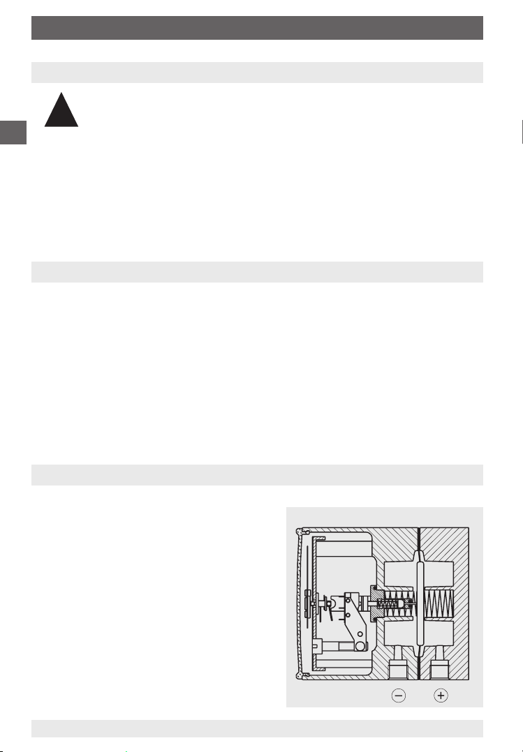
3. Operating principle
The j and i measuring medium chambers
are separated by an elastic diaphragm.
The differential pressure causes an
axial movement (measured travel) in the
diaphragm against the measuring range
spring. The measured travel is proportional
to the differential pressure and is transmitted, „pressure sealed“ and with minimal
friction, via a connecting rod; for:
su to the movement
st to the movement
and in addition to the plungers
on the microswitches
sv to the plungers
on the microswitches
4
WIKA Operating instructions DELTA-plus, DELTA-comb and DELTA-switch
Illustration for example st
2122740.01
2308215 07/2009 GB/D/F
Page 5
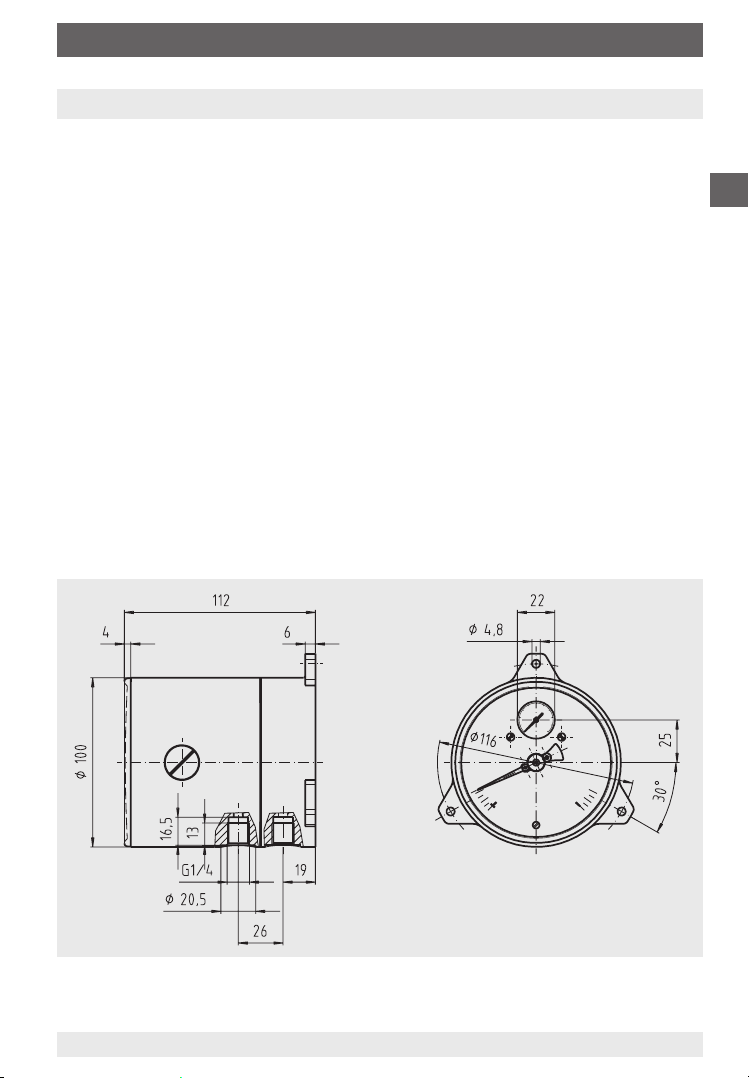
4. Installation instructions
4. Installation instructions
Installation of the differential pressure gauge should follow the installation
recommendations for pressure gauges according to EN 837-2 /7.
The maximum permissible medium / ambient temperature must not be
exceeded
Prior to the installation of the pressure gauge, the pipes should be
thoroughly cleaned by tapping, blowing or rinsing
The pressure gauges must be protected against contamination and high
temperature fluctuations!
The pressure gauges should be installed and operated such as to avoid
exposure to vibration. If the line to the pressure gauge is not robust enough
to prevent vibration it should be secured by means of brackets for wall
mounting.
Wall mounting
Installation using the three integral, cast mounting brackets
GB
2308215 07/2009 GB/D/F
WIKA Operating instructions DELTA-plus, DELTA-comb and DELTA-switch
2123541.01
5
Page 6
5. Measuring assembly / 6. Commissioning
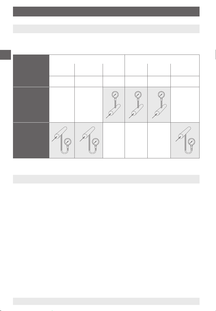
5. Measuring assembly
Proven measuring assemblies for various types of media. Recommended setup for pressure measurement instruments are shown below.
GB
Contents of
tail pipe
Typically
Pressure
instrument
higher than
tapping point
Pressure
instrument
lower than
tapping point
Liquid Liquid with
Condensate Boiling liquid LPG Dry air
Liquid media Gaseous media
vapour
Vapour
only
Gas only Wet gas Liquid gas
Most air
Flue gas
condensate
Steam
6. Commissioning
6.1 Mounting of the pressure connection
Pressure entries identified j and i j high pressure
i low pressure
6.2 Wiring details
(applies to Model 702.02.100 and 851.02.100)
The electrical connections should be made by qualified electricians
Connection details and switch functions are given on the instrument rating
plate. Connection terminals (1 ... 6) and the ground terminal are appropriately
marked.
The mains connection lines to be provided must be suitable for maximum
instrument power consumption and comply with IEC 227 or IEC 245
The instruments must be included in the equipotential bonding of the plant
6
WIKA Operating instructions DELTA-plus, DELTA-comb and DELTA-switch
2308215 07/2009 GB/D/F
Page 7
6. Commissioning
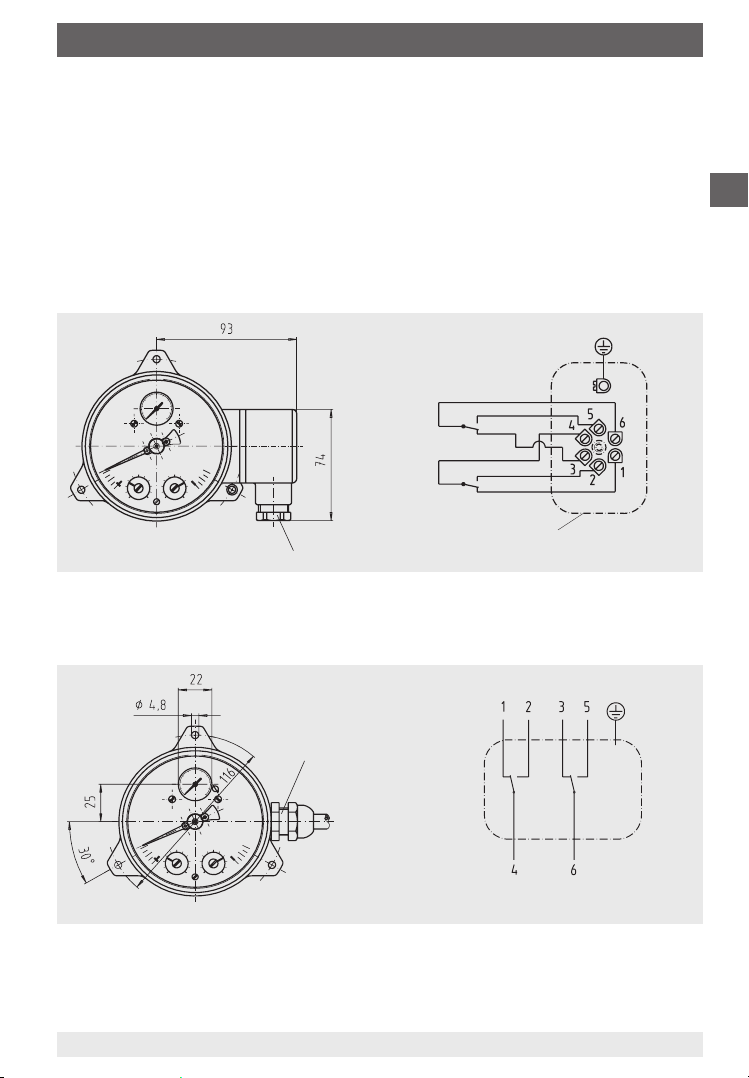
st and sv:
Power ratings (see data sheet)
Precise wiring schemes can be seen in the following drawings.
In addition to the wiring details and required power supply are given on the type
plate.
Electrical connection is by means
of terminal box or L-plug per DIN 43 651
2157306.0X
850.33 2nd contact
850.3 1st contact
Terminal box
M20 x 1,5
or electrical connection is by means
of cable gland and cable
Cable gland
M20 x 1.5
with 1 m cable
GB
2162679.01
2162679.0X
850.3
1st contact
2123568.0X
2308215 07/2009 GB/D/F
WIKA Operating instructions DELTA-plus, DELTA-comb and DELTA-switch
850.33
2nd contact
7
Page 8
6. Commissioning / 7. Options and accessories
6.3 Setting the switch point / checking the zero point
The switch points are set at the factory when the desired values are given. The
adjustment of the switch point is made by setpoint screws accessible from the
front. The assistant scales enable a relatively accurate adjustment of the switch
points over 270
GB
p° and indicate the setpoint that is momentarily adjusted.
For contact re-adjustment the snap-fit window is to be lifted off using a screw
driver at the recess in the circumference. The desired switch point can be set
by turning the contact adjustment screws with a screw driver.
If a more accurate switch point adjustment is desired, a test variable should be
used.
Afterwards press the window back into the case.
To check zero point see below
7. Options and accessories
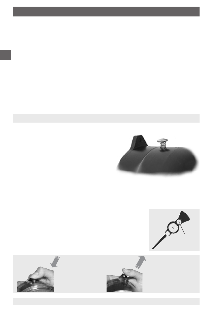
7.1 Integrated pressure equalising valve
The zero point check during the working
process is enabled by pushing the valve
button. The measuring medium flows from
the higher pressure side to the opposite
side and the differential pressure drops to
zero.
st and sv:
When the valve button is pushed, the differential pressure pointer must move
into the range of the zero point tolerance bar. As a consequence the function
of the instrument is in order. In the case of possible deviations beyond the
tolerance bar a zero point correction can be made via a standard integrated
adjustment pointer. For that purpose the snap-fit window
is to be lifted off using a screw driver at the impression/
recess in the circumference. The zero point is corrected
by turning the slotted screw at the adjustment pointer.
Afterwards the window is to be snap-fitted to the case
again. The differential pressure is indicated again, as soon
as the valve button is released.
Slotted
screw
Valve button
pushed
Differential pressure
is zero
8
WIKA Operating instructions DELTA-plus, DELTA-comb and DELTA-switch
Released
Differential pressure
is measured again
2308215 07/2009 GB/D/F
Page 9
7. Options and accessories
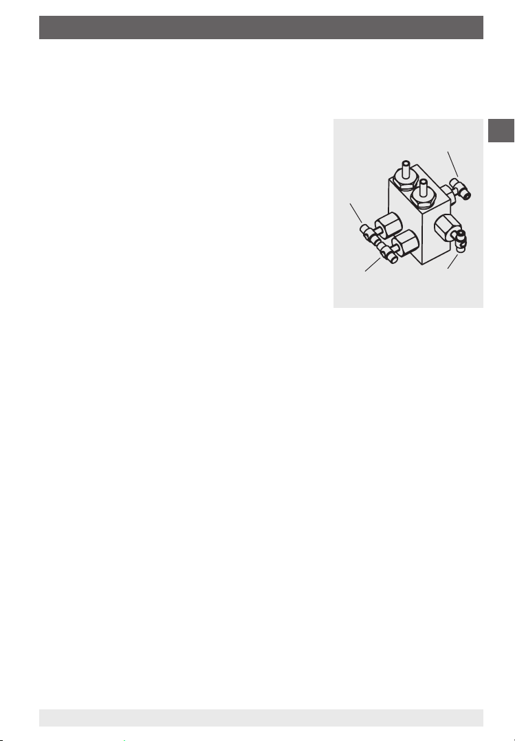
7.2 Four-way valve manifold
Shut off j- and i process line for disassembling and testing of
measuring instrument without interrupting the process that is running.
Protect the instrument against inadmissible
overpressure loading, such as, for example, in
the case of pressure tests and undefined
operating conditions (also temporary shut down).
Pressure equalising for zero point check during
normal operation as well as equalisation of the
pressures at high pressure and low pressure
side during start-up and operation (with opened
pressure equalising valve).
Process line air bleeding for liquid measuring
media and purging the process line for removing
impurities.
7.2.1 Handling instructions
Work sequence to start measuring
1. Open pressure equalising valve (middle valve)
2. Open shut-off valve of the negative-pressure media chamber (
valve) and the positive-pressure media chamber (
3. Close pressure equalising valve
Gauge valve,
high pressure
side j
Gauge valve,
low pressure
side i
j left valve)
Pressure
equalising valve
Valve for
purging or
air bleeding
i right
GB
Operating sequence for air bleeding/purging of piping
1. start: Open shut-off valve of the negative-pressure (
pressure (
j) media chamber
i) and positive-
Open pressure equalising valve and valve for purging or air bleeding
2. end: Close pressure equalising valve and valve for purging or air bleeding
Procedure at the end of the measuring operation
(also for partial system shut-down)
1. Open pressure equalising valve
2. Close shut-off valve of the negative-pressure (
(
j) media chamber
i) and positive-pressure
Task list for removing the transmitter during normal operation
1. Open pressure equalising valve
2. Close shut-off valve of the negative-pressure (
(
j) media chamber
3.
2308215 07/2009 GB/D/F
Open valve for purging or air bleeding
WIKA Operating instructions DELTA-plus, DELTA-comb and DELTA-switch
i) and positive-pressure
9
Page 10

7. Options and accessories ... 11. Disposal
7.3 Front flange for panel mounting
GB
Panel cut-out
Panel
2123649.0Y
8. Storage
Before installation, in order to prevent damage from the pressure gauges, follow
the subsequent points:
The pressure gauge should remain in its original packing until installation
After taking out the pressure gauge (e.g. for tests) reuse the original
packaging material
Storage temperature should not exceed -20 °C ... +60 °C
Pressure gauges should be protected against dust and humidity
9. Maintenance and servicing / cleaning
These WIKA differential pressure gauges will give very long service when
handled and operated properly. Control and safety devices are to be checked
for their efficiency (see also VDI 3033 Table1).
The instruments should be cleaned with a damp cloth, moistened with soap
solution. The residual pressure medium in dismounted pressure gauges may be
hazardous or toxic. This should be considered when handling and storing the
removed pressure gauges.
10. Repairs
Repairs should only be carried out by the manufacturer or appropriately trained
personnel. For further technical details see WIKA data sheet PM 07.15,
PV 27.16 or PV 27.17.
11. Disposal
Dispose of instrument components and packaging materials in accordance
with the respective waste treatment and disposal regulations of the region or
country to which the instrument is supplied.
10
WIKA Operating instructions DELTA-plus, DELTA-comb and DELTA-switch
2308215 07/2009 GB/D/F
Page 11

Inhalt
Inhalt
1. Sicherheitshinweise 12
2. Allgemeines 12
3. Funktionsprinzip 12
4. Montagehinweise 13
5. Messanordnungen 14
6. Inbetriebnahme 14
7. Optionen und Zubehör 16
8. Lagerung 18
9. Wartung / Reinigung 18
10. Reparaturen 18
11. Entsorgung 18
D
2308215 07/2009 GB/D/F
WIKA Betriebsanleitung DELTA-plus, DELTA-comb und DELTA-switch
11
Page 12

1. Sicherheitshinweise ... 3. Funktionsprinzip
1. Sicherheitshinweise
Beachten Sie unbedingt bei Montage, Inbetriebnahme und Betrieb
dieser Geräte die entsprechenden nationalen Sicherheitsvorschriften
!
Vorsicht
Alle Arbeiten dürfen nur im spannungslosen Zustand erfolgen (betrifft Typen
D
702.02/03.100 und 851.02.100)
Bei Nichtbeachten der entsprechenden Vorschriften können schwere Körper-
verletzungen und/oder Sachschäden auftreten
Nur entsprechend qualifiziertes Personal darf an diesen Geräten arbeiten
(z. B. VDE 0100 / EN 60 079-14 / EN 837-2).
2. Allgemeines
Vorliegende Betriebsanleitung baut auf folgenden Informationen auf:
EN 837-2: Auswahl- und Einbauempfehlungen für Druckmessgeräte
Datenblatt PM 07.15: Differenzdruckmessgerät mit integrierter Betriebs-
druckanzeige
Datenblatt PV 27.16: Differenzdruckmessgerät mit integrierter Betriebs-
druckanzeige und Mikroschalter
Typ 702.02.100
Datenblatt PV 27.17: Differenzdruck-Schaltgerät
su Typ 702.01.100
T
sv Typ 851.02.100
3. Funktionsprinzip
Die j- und i- Messstoffkammern sind durch eine elastische Membrane
getrennt. Der Differenzdruck bewirkt eine
axiale Auslenkung (Messweg) der Membrane gegen die Messbereichsfeder. Der
dem Differenzdruck proportionale Messweg
wird über eine Schubstange druckdicht und
reibungsarm übertragen; bei:
su auf ein Zeigerwerk
st auf ein Zeigerwerk
und zusätzlich an die Stößel der
Mikroschalter
sv an die Stößel der
Mikroschalter
12
WIKA Betriebsanleitung DELTA-plus, DELTA-comb und DELTA-switch
Darstellung am Beispiel st
2122740.01
2308215 07/2009 GB/D/F
Page 13

4. Montagehinweise
4. Montagehinweise
Die Montage des Differenzdruckmessgerätes erfolgt in Anlehnung an die
Einbauempfehlung für Druckmessgeräte nach EN 837-2 /7.
Die maximal zulässige Messstoff-/Umgebungstemperatur darf nicht über-
schritten werden
Messleitungen vor der Gerätemontage gründlich durch Abklopfen und
Ausblasen oder Durchspülen reinigen
Messgeräte vor Verschmutzung und starken Temperaturschwankungen
schützen!
Messgeräte sollen erschütterungsfrei montiert und betrieben werden.
Ist die Leitung zum Druckmessgerät für eine erschütterungsfreie Anbringung
nicht stabil genug, so ist die Befestigung über die Befestigungslaschen zur
Wandmontage vorzunehmen.
Wandmontage
Befestigung über drei angegossene Befestigungslaschen
D
2308215 07/2009 GB/D/F
WIKA Betriebsanleitung DELTA-plus, DELTA-comb und DELTA-switch
2123541.01
13
Page 14

5. Messanordnungen / 6. Inbetriebnahme
5. Messanordnungen
Bewährte Messanordnungen für verschiedene Messstoffarten. Die zur Anwendung besonders empfohlenen Anordnungen sind nachfolgend dargestellt.
Füllung der
D
Messleitung
Beispiele
flüssige Messstoffe gasförmige Messstoffe
flüssig zum Teil
ausgasend
Kondensat siedende
Flüssigkeiten
vollständig
verdampft
„Flüssiggase“
gasförmig zum Teil
trockene
Luft
Druckmessgerät oberhalb des
Entnahmestutzens
Druckmessgerät unterhalb des
Entnahmestutzens
6. Inbetriebnahme
6.1 Montage der Druckanschlüsse
Nach angebrachten Symbolen j und i j hoher Druck
i niedriger Druck
6.2 Elektrischer Anschluss
(betrifft Typen 702.02.100 und 851.02.100)
kondensiert
(feucht)
feuchte Luft
Rauchgase
vollständig
kondensiert
Wasserdampf
Der elektrische Anschluss darf nur durch qualifiziertes Personal erfolgen
Die Belegung der Anschlüsse und die Schaltfunktionen sind auf dem Typen-
schild am Gerät angegeben und die Anschlußklemmen (1 ... 6) sowie die
Erdungsklemme sind entsprechend gekennzeichnet.
Die vorgesehenen Netzanschlussleitungen müssen für die größte Stromauf-
nahme des Gerätes bemessen sein und IEC 227 oder IEC 245 entsprechen
Die Geräte sind in den Potenzialausgleich der Anlage mit einzubeziehen
14
WIKA Betriebsanleitung DELTA-plus, DELTA-comb und DELTA-switch
2308215 07/2009 GB/D/F
Page 15

6. Inbetriebnahme
st und sv:
Leistungsdaten (siehe Datenblatt)
Die genauen Anschlussbelegungen können dem nachfolgenden Anschlussschema entnommen werden. Zusätzlich sind Anschlussbelegung und erforderliche Hilfsenergie auf dem Typenschild am Gehäuseumfang vermerkt.
Elektrischer Anschluss über
Kabeldose oder Winkelstecker nach DIN 43 651
D
M20 x 1,5
oder elektrischer Anschluss über
Kabelverschraubung und Kabel
Kabelverschraubung
M20 x 1,5
mit 1 m Kabel
2157306.0X
2123568.0X
850.33 2. Kontakt
850.3 1. Kontakt
Kabelanschlussdose
850.3
1. Kontakt
850.33
2. Kontakt
2162679.01
2162679.0X
2308215 07/2009 GB/D/F
WIKA Betriebsanleitung DELTA-plus, DELTA-comb und DELTA-switch
15
Page 16

6. Inbetriebnahme / 7. Optionen und Zubehör
6.3 Schaltpunkteinstellung / Nullpunktüberprüfung
Bei Angabe der Sollwerte werden werkseitig die Schaltpunkte eingestellt.
Die Schaltpunktverstellung erfolgt über frontseitig zugängliche Einstellschrauben. Eine Hilfsskala über 270
p° ermöglicht eine relativ genaue Schalt-
punktjustierung und zeigt den momentan eingestellten Sollwert.
Zur Kontaktverstellung Schnappscheibe mittels Schraubendreher an der am
Umfang angebrachten Einprägung/Aussparung abheben. Durch Drehen der
D
Kontakt-Einstellschrauben mittels Schraubendreher kann gewünschter Schaltpunkt eingestellt werden.
Wird eine noch genauere Schaltpunkteinstellung gewünscht, sollte ein Prüfnormal zur Justage verwendet werden.
Anschließend die Sichtscheibe wieder in das Gehäuse eindrücken.
Nullpunktprüfung siehe unten
7. Optionen und Zubehör
7.1 Integriertes Druckausgleichsventil
Durch Betätigen des Druckknopfes wird
eine Nullpunktkontrolle im laufenden
Betriebsprozess ermöglicht. Der Messstoff
strömt von der Seite höheren Druckes
nach der Gegenseite und der Differenzdruck am Messgerät fällt auf Null.
st und sv:
Durch Betätigen des Druckknopfes muss die Differenzdruckanzeige auf Null,
d.h. in den Bereich des Nullpunkt-Toleranzbalkens gehen. Die Gerätefunktion ist damit in Ordnung. Bei möglichen Abweichungen, die außerhalb des
Toleranzbalkens liegen, kann eine Nullpunktkorrektur über den standardmäßig eingebauten Verstellzeiger erfolgen. Dazu ist die
Schnappscheibe mittels Schraubendreher an der am
Umfang angebrachten Einprägung/Aussparung abzuheben. Die Nullpunkt-Verstellung wird durch ein Verdrehen
der Schlitzschraube am Verstellzeiger erreicht. Anschließend ist die Schnappscheibe wieder auf dem Gehäuse
aufzubringen. Der Differenzdruck wird wieder angezeigt,
Schlitzschraube
sobald der Druckkopf freigeben wird.
16
Ventil betätigt
Differenzdruck
gleich Null
WIKA Betriebsanleitung DELTA-plus, DELTA-comb und DELTA-switch
Losgelassen
Differenzdruck wird
wieder gemessen
2308215 07/2009 GB/D/F
Page 17

7. Optionen und Zubehör
7.2 Vierfach-Ventilblock
Absperrung der j- und i- Prozessleitung zur Demontage oder Prüfung
des Messgerätes ohne Störung des laufenden Betriebsprozesses.
Schutz des Gerätes gegen unzulässige
Überdruckbelastung, wie z. B. bei Druckprüfungen und undefinierten Betriebsverhältnissen
(auch zeitweiliger Stilllegung).
Absperrventil
Druckausgleich zur Nullpunktkontrolle bei
j-Seite
laufenden Prozess sowie Vermeidung einseitiger
Überdruckbelastung während der Anfahr- bzw.
Betriebsphase (bei geöffnetem Druckausgleichsventil).
Entlüftung der Messleitungen bei flüssigen
Messstoffen und Spülung der Messleitungen um
Verunreinigungen zu entfernen.
7.2.1 Angaben zum Handling
Arbeitsgangfolge zum Messanfang
1. Druckausgleichsventil (mittlere Ventilspindel) öffnen
2. Absperrventil der Minus-Messstoffkammer (
Plus-Messstoffkammer (
j, linkes Ventil) öffnen
i, rechtes Ventil) und der
3. Druckausgleichsventil schließen
Absperrventil
i-Seite
Druckausgleichsventil
Entlüftungsventil
D
Arbeitsgangfolge zum Spülen/Entlüften der Messleitungen
1. Anfang: Absperrventil der i- und j- Messstoffkammer öffnen
Druckausgleichsventil und Entlüftungsventil öffnen
2. Ende: Druckausgleichsventil und Entlüftungsventil schließen
Arbeitsgangfolge zu Messende (auch zeitweise Stilllegung)
1. Druckausgleichsventil öffnen
2. Absperrventil der
i- und j- Messstoffkammer schließen
Arbeitsgangfolge zur Demontage des Messgerätes bei laufenden Prozess
1. Druckausgleichsventil öffnen
2. Absperrventil der
3.
Entlüftungsventil öffnen
2308215 07/2009 GB/D/F
WIKA Betriebsanleitung DELTA-plus, DELTA-comb und DELTA-switch
i- und j- Messstoffkammer schließen
17
Page 18

7. Optionen und Zubehör ... 11. Entsorgung
7.3 Befestigungsrand für Schalttafelmontage
2123649.0Y
D
Ausschnitt
Schalttafel
8. Lagerung
Für die Lagerung der Druckmessgeräte bis zur Montage sind, um Schäden zu
vermeiden, folgende Punkte zu beachten:
Druckmessgeräte in der Originalverpackung belassen
Nach einer eventuellen Entnahme der Messgeräte (z. B. für Prüfungen) ist die
Originalverpackung wieder zu verwenden
Lagertemperaturbereich -20 °C ... +60 °C
Messgeräte vor Feuchtigkeit und Staub schützen
9. Wartung / Reinigung
Diese WIKA-Differenzdruckmessgeräte zeichnen sich bei sachgemäßer
Behandlung und Bedienung durch eine hohe Lebensdauer aus. Regel- und
Sicherheitseinrichtungen sind auf ihre Wirksamkeit zu überprüfen (siehe auch
VDI 3033 Tafel1).
Reinigen der Geräte mit einem (in Seifenlauge) angefeuchteten Tuch.
Messstoffreste in ausgebauten Druckmessgeräten können zur Gefährdung von
Menschen, Umwelt und Einrichtungen führen. Ausreichende Vorsichtsmaßnahmen sind zu ergreifen.
10. Reparaturen
Reparaturen sind ausschließlich vom Hersteller oder entsprechend geschultem
Personal durchzuführen. Weitere technische Daten bitte dem WIKA Datenblatt
PM 07.15, PV 27.16 oder PV 27.17 entnehmen.
11. Entsorgung
Entsorgen Sie Gerätekomponenten und Verpackungsmaterialien entsprechend
den einschlägigen landesspezifischen Abfallbehandlungs- und Entsorgungsvorschriften des Anliefergebietes.
18
WIKA Betriebsanleitung DELTA-plus, DELTA-comb und DELTA-switch
2308215 07/2009 GB/D/F
Page 19

Sommaire
Sommaire
1. Consignes de sécurité 20
2. Généralités 20
3. Principe de fonctionnement 20
4. Instructions de montage 21
5. Dispositions de montage 22
6. Mise en service 22
7. Options / accessoires 24
8. Stockage 26
9. Entretien / nettoyage 26
10. Réparations 26
11. Mise au rebus 26
F
2308215 07/2009 GB/D/F
Mode d'emploi WIKA DELTA-plus, DELTA-comb et DELTA-switch
19
Page 20

1. Consignes de sécurité ... 3. Principe de fonctionnement
1. Consignes de sécurité
Les prescriptions de sécurité nationales en vigueur (par exemple
VDE 0100 / EN 60 079-14 / EN 837-2) doivent absolument être
!
Vorsicht
Toutes les interventions doivent être effectuées hors tension (concerne les
types 702.02/03.100 et 851.02.100)
F
Le non-respect des instructions correspondantes est susceptible d‘entraîner
des risques de blessure et/ou des dégâts matériels
Seul le personnel habilité et qualifié est autorisé à manipuler les instruments
respectées lors du montage, de la mise en service et de l‘utilisation
des instruments ici présentés.
2. Généralités
Le présent mode d‘emploi repose sur les informations suivantes:
EN 837-2: Recommandations pour le choix et l‘installation de manomètres
Fiche technique PM 07.15 : Manomètre pour pression différentielle avec
indication de la pression de travail su Type 702.01.100
Fiche technique PV 27.16 : Manomètre pour pression différentielle avec
indication de la pression de travail et microcontact T Type 702.02.100
Fiche technique PV 27.17 : Pressostat différentiel sv Type 851.02.100
3. Principe de fonctionnement
Les chambres de mesure j- et i- sont séparées par une membrane élastique.
La différence de pression provoque
un déplacement axial de la membrane
(chemin de mesure) contre le ressort
de l‘étendue de mesure. Le déplacement proportionnel à la différence de
pression est transmis avec un frottement minimal par une biellette étanche
en fonction du type d‘appareil :
su à un mouvement
st à un mouvement et en
plus au poussoir du microcontact
sv
20
au poussoir du microcontact
Mode d'emploi WIKA DELTA-plus, DELTA-comb et DELTA-switch
Exemple de présentation d'un st
2122740.01
2308215 07/2009 GB/D/F
Page 21

4. Instructions de montage
4. Instructions de montage
Le montage de l‘appareil de mesure de pression différentielle s‘effectue en
référence à la recommandation pour l‘installation des appareils de mesure de
pression selon EN 837-2/7.
Les températures maximales autorisées pour le fluide et l‘environnement ne
doivent pas être dépassées
Avant le montage de l‘appareil, nettoyer à fond la tuyauterie en tapant
dessus ou en soufflant à l‘air comprimé ou en les rinçant
Protéger les appareils de mesure de la pollution et des variations de
température élevées!
Les appareils de mesure doivent être installés et utilisés de façon à ne pas
être soumis à des vibrations. Un découplage du lieu de montage avec
vibrations peut être obtenu, par exemple par l‘installation de l‘appareil de
mesure sur une paroi rigide avec pose d‘une conduite flexible entre l‘appareil
de mesure et le point de mesure.
Montage sur parol
Fixation à l‘aide de trois oeillets intégrés
F
2308215 07/2009 GB/D/F
Mode d'emploi WIKA DELTA-plus, DELTA-comb et DELTA-switch
2123541.01
21
Page 22

5. Dispositions de montage / 6. Mise en service
5. Dispositions de montage
Dispositions de montage éprouvées pour différents fluides. Les dispositions
particulièrement recommandables sont décrites ci-après.
Remplissage de la
conduite de
mesure
F
Exemples
liquides en partie
condensat liquides en
fluides liquides fluides gazeux
dégazés
ébullition
complètement
évaporés
„gaz liquides“ air sec
gazeux en partie
condensés
(humides)
air humide
gaz de fumées
Manomètre
au-dessus
du point de
mesure
Manomètre
en-dessous
du point de
mesure
6. Mise en service
complètement
condensés
vapeur d‘eau
6.1 Montage des raccords process
Selon les symboles indiqués j et i j pression élevée
i pression basse
6.2 Branchement électrique
(concerne les types 702.02.100 et 851.02.100)
Le branchement électrique ne peut être effectué que par du personnel
qualifié
La position des branchements et les fonctions de commutation sont
indiquées sur la plaquette signalétique de l‘appareil, les bornes de branchement (1 ... 6) ainsi que la borne de terre sont marquées en conséquence.
Les conducteurs secteurs prévus doivent être adaptés à la puissance
consommée la plus élevée du courant de l‘appareil et correspondre à
IEC 227 ou IEC 245
Les appareils doivent être intégrés dans la compensation de potentiel du site
22
Mode d'emploi WIKA DELTA-plus, DELTA-comb et DELTA-switch
2308215 07/2009 GB/D/F
Page 23

6. Mise en service
st und sv:
Caractéristiques (voir fiche technique)
Les affectations exactes peuvent être prélevées sur le schéma de branchement
ci-après. En plus, l‘affectation de branchement et l‘alimentation nécessaire sont
indiquées sur la plaque signalétique du boîtier.
Branchement électrique
Branchement par boîte de jonction ou fiche coudée selon DIN 43 651
ou branchement électrique
Branchement par presse-étoupe et câble
2157306.0X
850.33 2ème contact
850.3 1er contact
M20 x 1,5
Câble avec presse-étoupe
M20 x 1,5 avec
câble longueur 1 m
Boîte de jonction
850.3
1er contact
850.33
2ème contact
F
2162679.01
2162679.0X
2123568.0X
2308215 07/2009 GB/D/F
Mode d'emploi WIKA DELTA-plus, DELTA-comb et DELTA-switch
23
Page 24

6. Mise en service / 7. Options / accessoires
6.3 Réglage des points de commutation / Contrôle du point zéro
Les réglages des points de commutation s‘effectuent par des vis de réglage
depuis la face avant. L‘échelle d‘assistance de 270
p° permet un réglage du
point de commutation relativement exact et indique la valeur de consigne
réglée actuellement.
Afin de déplacer le contact, il faut tout d‘abord ouvrir le voyant en le soulevant par les rainures se trouvant sur sa périphérie. La valeur de point de seuil
requise est obtenue en tournant la vis de réglage.
F
Si on souhaite un réglage du point de commutation encore plus précis, il faut
utiliser un étalon de contrôle pour le réglage.
Ensuite remonter le voyant en le clipsant sur le boîtier.
Contrôle du point zéro voir ci-après
7. Options / accessoires
7.1 Valve de compensation de pression intégrée
En appuyant sur le poussoir on permet un
contrôle du zéro en cours de fonctionnement du process.
Le fluide passe du côté haute pression au
côté opposé et la différence de pression
passe à zéro.
st et sv:
Quand on appuye sur le poussoir l‘affichage de la pression différentielle doit
passer à zéro, c‘est à dire doit se trouver dans la barre de tolérance du zéro.
La fonction de l‘appareil est alors correcte. En cas d‘une dérive hors de la barre
de tolérance du zéro, une correction du zéro peut être faite par l‘aiguille micrométrique réglable montée de série.
Pour ce faire, il faut tout d‘abord ouvrir le voyant en
le soulevant à l‘aide d‘un tournevis par les rainures se
trouvant sur sa périphérie. Le réglage du zéro se fait en
tournant la vis se trouvant sur l‘aiguille réglable. Ensuite
remonter le voyant en le clipsant sur le boîtier. La pression
Vis à fente
différentielle sera de nouveau affichée dès qu‘on relâche
le bouton.
24
Vanne
manœuvrée
Pression différentielle
égale à zéro
Mode d'emploi WIKA DELTA-plus, DELTA-comb et DELTA-switch
relâchée
Pression différentielle
est de nouveau mesurée
2308215 07/2009 GB/D/F
Page 25

7. Options / accessoires
7.2 Manifold 4 voies
Fermeture des conduites de processus j et i pour le démontage ou le
contrôle de l‘appareil de mesure sans perturber le process en cours.
Protection de l‘appareil contre les surpres-
sions, comme par exemple lors de contrôles de
pression et des conditions de fonctionnement
indéfinies (également lors de la mise hors service
temporaire).
Equilibrage de la pression pour le contrôle du
Robinet
d‘isolement
côté j
zéro en cours de process ainsi que pour éviter
une surpression unilatérale pendant le démarrage ou le service de l‘installation (avec vanne
d‘équilibre de pression ouverte).
Ventilation des conducteurs de mesure de
fluides liquides et rinçage des conducteurs afin
d‘éliminer des impuretés.
Robinet
d‘isolement
côté i
7.2.1 Indications de l‘utilisation
Déroulement des opérations en début de mesure
1. Ouvrir la vanne d‘équilibrage de pression (vanne du milieu)
2. Ouvrir le robinet d‘isolement du côté négatif de la chambre de mesure
(
i, robinet de droite), ensuite ouvrir le robinet d‘isolement du côté positif
de la chambre de mesure (
j, robinet de gauche)
3. Fermer la vanne d‘équilibrage de pression
Vanne d‘équilibre
de pression
Vanne de
purge
F
Déroulement des opérations pour le rinçage / la ventilation des conduites
de mesure
1. Début: Ouvrir les robinets
i et j de la chambre de mesure
Ouvrir la vanne d‘équilibrage de pression et la vanne de purge
2. Fin: Fermer la vanne d‘équilibrage de pression et la vanne de purge
Déroulement des opérations en fin de mesure (également lors de la mise
hors service temporaire)
1. Ouvrir la vanne d‘équilibrage de pression
2. Fermer les robinets
Déroulement des opérations pour le démontage de l‘appareil de mesure en
i et j de la chambre de mesure
cours de fonctionnement du process
1. Ouvrir la vanne d‘équilibrage de pression
2. Fermer les robinets
3.
Ouvrir la vanne de purge
2308215 07/2009 GB/D/F
Mode d'emploi WIKA DELTA-plus, DELTA-comb et DELTA-switch
i et j de la chambre de mesure
25
Page 26

7. Options / accessoires ... 11. Mise au rebus
7.3 Collerette avant pour le montage sur panneau
2123649.0Y
F
Découpure
Panneau
8. Stockage
Pour stocker les transmetteurs de pression en attendant leur montage, il est
nécessaire - afin d‘éviter des dégats - de respecter les points suivants:
Laisser les transmetteurs de pression dans leur emballage d‘origine.
Après avoir prélevé un transmetteur de pression (par exemple pour un
contrôle) le réemballer dans son emballage d‘origine.
Température de stockage -20 °C ... +60 °C
Protéger les appareils de l‘humidité et de la poussière.
9. Entretien / Nettoyage
S‘ils sont manipulés et utilisés correctement, les manomètres pour pression
différentielle WIKA se distinguent par une longue durée de vie. Control and
safety devices are to be checked for their efficiency (see also VDI 3033 Table1).
L‘appareil se nettoie à l‘aide d‘un chiffon humidifié (avec du savon).
Des restes de fluide se trouvant dans les manomètres démontés peuvent
provoquer une mise en danger de personnes, de l‘environnement et de l‘équi-
pement. Des précautions adéquates sont à prendre.
10. Réparations
Toute réparation doit être exclusivement confiée au fabricant ou à du personnel
qualifié correspondant. Pour autres données, se reporter à la fiche technique
de l‘instrument correspondant (PM 07.15, PV 27.16 ou PV 27.17)
11. Mise au rebus
Mettez les composants des appareils et les emballages au rebus en respectant
les prescriptions nationales pour le traitement et la mise au rebus des régions
ou pays de livraison.
26
Mode d'emploi WIKA DELTA-plus, DELTA-comb et DELTA-switch
2308215 07/2009 GB/D/F
Page 27

WIKA Global
Europe
Austria
WIKA Messgerätevertrieb
Ursula Wiegand GmbH & Co. KG
1230 Vienna
Phone: (+43) 1-86 91 631
E-mail: info@wika.at
www.wika.at
Benelux
WIKA Benelux
6101 WX Echt
Phone: (+31) 475-535 500
E-mail: info@wika.nl
www.wika.nl
Bulgaria
WIKA Bulgaria EOOD
1309 Sofia
Phone: (+359) 2 82138-10
E-mail: t.antonov@wika.bg
Croatia
WIKA Croatia d.o.o.
Hrastovička 19
10250 Zagreb-Lučko
Phone: (+385) 1 6531034
E-mail: info@wika.hr
Finland
WIKA Finland Oy
00210 Helsinki
Phone: (+358) 9-682 49 20
E-mail: info@wika.fi
www.wika.fi
France
WIKA Instruments s.a.r.l.
95610 Eragny-sur-Oise
Phone: (+33) 1-34 30 84 84
E-mail: info@wika.fr
www.wika.fr
Germany
WIKA Alexander Wiegand
SE & Co. KG
63911 Klingenberg
Phone: (+49) 93 72-13 20
Fax: (+49) 93 72-13 24 06
E-mail: info@wika.de
www.wika.de
2308215 07/2009 GB/D/F
Italy
WIKA Italiana SRL
20020 Arese (Milano)
Phone: (+39) 02-93 86 11
Fax: (+39) 02-93 86 174
E-mail: info@wika.it
www.wika.it
Poland
WIKA Polska S.A.
87-800 Wloclawek
Phone: (+48) 542 30 11 00
E-mail: info@wikapolska.pl
www.wikapolska.pl
Romania
WIKA Instruments Romania S.R.L.
Bucuresti, Sector 5
Calea Rahovei Nr. 266-268
Phone: (+40) 21 4563138
E-mail: m.anghel@wika.ro
Russia
ZAO „WIKA Mera“
127015 Moscow
Phone: (+7) 495-648 01 80
E-mail: info@wika.ru
www.wika.ru
Serbia
WIKA Merna Tehnika d.o.o.
11060 Belgrade
Phone: (+381) 11 27 63 722
E-mail: info@wika.co.yu
www.wika.co.yu
Spain
Instrumentos WIKA, S.A.
08205 Sabadell (Barcelona)
Phone: (+34) 902 902 577
E-mail: info@wika.es
www.wika.es
Switzerland
Manometer AG
6285 Hitzkirch
Phone: (+41) 41-919 72 72
E-mail: info@manometer.ch
www.manometer.ch
Turkey
WIKA Alexander Wiegand
GmbH & Co. KG, Türkiye
Maltepe - Istanbul
Phone: (+90) 216/305 46 24
E-mail: info@wika.com.tr
www.wika.com.tr
Ukraine
WIKA Pribor GmbH
83016 Donetsk
Phone: (+38) 062 345 34 16
E-mail: info@wika.ua
www.wika.ua
United Kingdom
WIKA Instruments Ltd
Merstham, Redhill RH13LG
Phone: (+44) (0) 1737 644 008
E-mail: info@wika.co.uk
www.wika.co.uk
North America
Canada
WIKA Instruments Ltd.
Head Office
Edmonton, Alberta, T6N 1C8
Fax: (+1) 780-462 00 17
E-mail: info@wika.ca
www.wika.ca
Mexico
Instrumentos WIKA Mexico S.A.
de C.V.,
01210 Mexico D.F.
Phone: (+52) 555 020 53 00
E-mail: ventas@wika.com
www.wika.com.mx
USA
WIKA Instrument Corp.
Lawrenceville, GA 30043
Phone: (+1) 770-513 82 00
E-mail: info@wika.com
www.wika.com
South America
Argentina
WIKA Argentina S.A.
Buenos Aires
Phone: (+54) 11-4730 18 00
E-mail: info@wika.com.ar
www.wika.com.ar
Brazil
WIKA do Brasil Ind. e Com.
Ltda.
CEP 18560-000 Iperó - SP
Phone: (+55) 15-3459 97 00
E-mail: marketing@wika.com.br
www.wika.com.br
WIKA Betriebsanleitung DELTA-plus, DELTA-comb und DELTA-switch
Page 28

WIKA Global
Africa / Middle East
Egypt
WIKA Alexander Wiegand
GmbH & Co. KG, El-Serag
Nasr City, Cairo
Phone: (+20) 2 2287 6219
Fax: (+20) 2 2273 3140
E-mail: ahmed.azab@wika.de
South Africa
WIKA Instruments (Pty.) Ltd.
Johannesburg 2047
Phone: (+27) 11-621 00 00
E-mail: sales@wika.co.za
www.wika.co.za
United Arab Emirates
WIKA Middle East FZE
Jebel Ali, Dubai
Phone: (+971) 4-883 90 90
E-mail: wikame@emirates.net.ae
Asia
China
WIKA International Trading
(Shanghai) Co., Ltd.
200001 Shanghai
Phone: (+86) 21-53 85 25 72
E-mail: info@wika.com.cn
India
WIKA Instruments India Pvt.
Village Kesnand, Wagholi
Pune - 412 207
Phone: (+91) 20-66 29 32 00
E-mail: sales@wika.co.in
www.wika.co.in
Japan
WIKA Japan K. K.
Tokyo 105-0023
Phone: (+81) 3-54 39 66 73
Fax: (+81) 3-54 39 66 74
E-mail: t-shimane@wika.co.jp
Kazakhstan
TOO WIKA Kazakhstan
050050 Almaty
Phone: (+7) 32 72 33 08 48
Fax: (+7) 32 72 78 99 05
E-mail: info@wika.kz
Korea
WIKA Korea Ltd.
Seoul 153-023
Phone: (+82) 2 - 8 69 05 05
Fax: (+82) 2 - 8 69 05 25
E-mail: info@wika.co.kr
Malaysia
WIKA Instrumentation (M) Sdn.
Bhd.
47100 Puchong, Selangor
Phone: (+03) 80 63 10 80
Fax: (+03) 80 63 10 70
E-mail: info@wika.com.my
www.wika.com.my
Singapore
WIKA Instrumentation Pte. Ltd.
569625 Singapore
Phone: (+65) 68 44 55 06
E-mail: info@wika.com.sg
www.wika.com.sg
Taiwan
WIKA Instrumentation Taiwan
Ltd.
Pinjen, Taoyuan
Phone: (+886) 3 420 6052
E-mail: info@wika.com.tw
www.wika.com.tw
Australia
Australia
WIKA Australia Pty. Ltd.
Rydalmere, NSW 2116
Phone: (+61) 2-88 45 52 22
E-mail: sales@wika.com.au
www.wika.com.au
New Zealand
Process Instruments Limited
Unit 7 / 49 Sainsbury Road
St Lukes - Auckland 1025
Phone: (+64) 9 - 847 90 20
E-mail: info@wika.co.nz
www.wika.co.nz
Technical alteration rights reserved.
Technische Änderungen vorbehalten.
Sous réserve de modifications techniques.
WIKA Alexander Wiegand SE & Co. KG
Alexander-Wiegand-Straße 30
63911 Klingenberg • Germany
Tel. (+49) 9372/132-0
Fax (+49) 9372/132-406
E-Mail info@wika.de
www.wika.de
28
2308215.03 07/2009 GB/D/F
 Loading...