

Operating Instructions
Betriebsanleitung
Instructions d'utilisation
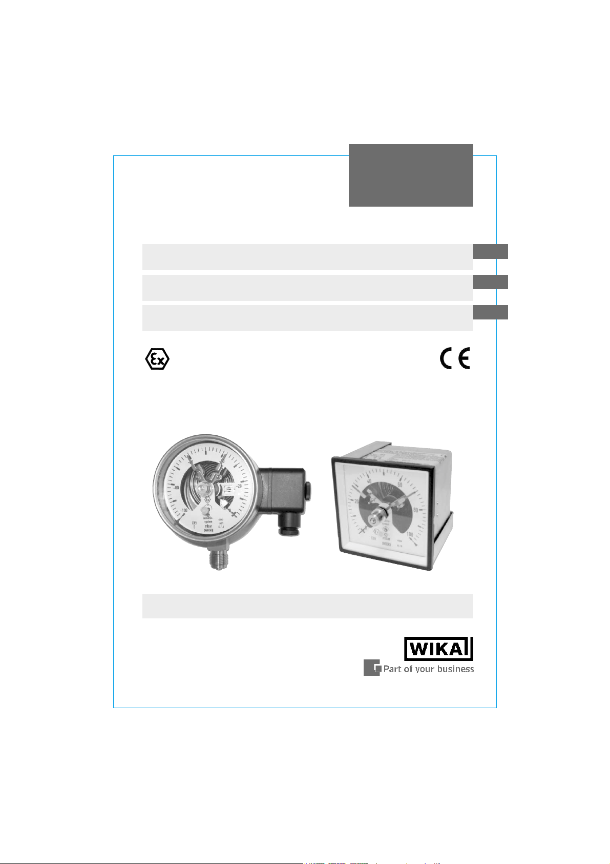
Pressure gauges Model 6 per directive 94/9/EC (ATEX)
with inductive alarm sensors Model 831
Druckmessgeräte Typ 6 nach Richtlinie 94/9/EG (ATEX)
mit Induktiv-Grenzsignalgeber Typ 831
Manomètres Type 6 selon directive 94/9/EG (ATEX)
avec seuil d'alarme inductif Type 831
II 2 GD c
GB
D
F
Model 632.50.100 and Model 614.11.96x96
per ATEX with inductive alarm sensors Model 831.12
GB
Operating instructions Model 6 per ATEX
with Model 831 Page 1-22
Betriebsanleitung Typ 6 nach ATEX
D
mit Typ 831 Seite 23-42
Instructions d'utilisation Type 6 selon ATEX
F
avec Type 831 Page 43-49
2 WIKA Operating instructions pressure gauges Model 6 with 831 per ATEX
2030660 12/2004 GB/D/F

Contents
Contents
Contents
1. Safety instructions 4
2. Description 4
3. Technical data and use in accordance with
intended use 5
4. Alarm contacts 7
5. Commissioning 9
6. Maintenance and servicing / cleaning 9
7. Repairs 9
Enclosure 1: Declaration of conformity for Models 53X
with inductive alarm sensors Model 831 10
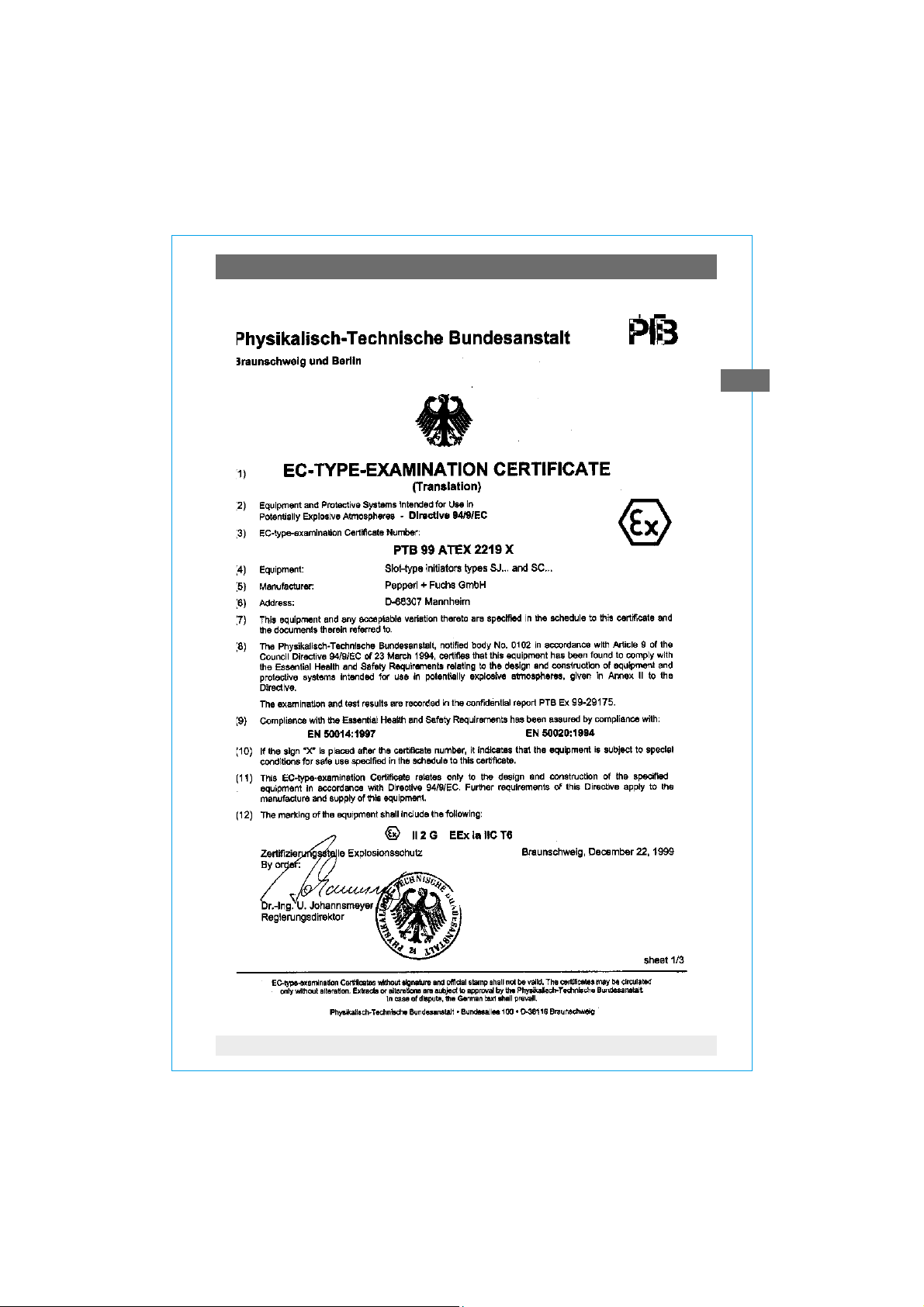
Enclosure 2: EC-type examination certificate (gases)
for slot-type initiators types SJ and SC
(WIKA-Model 831) 11-13
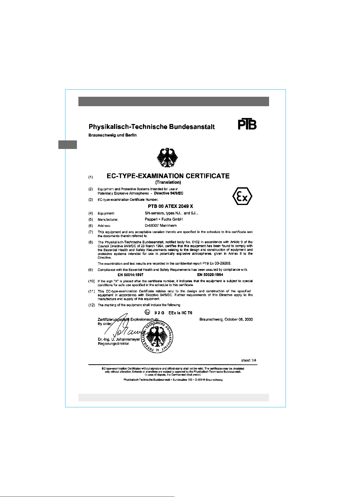
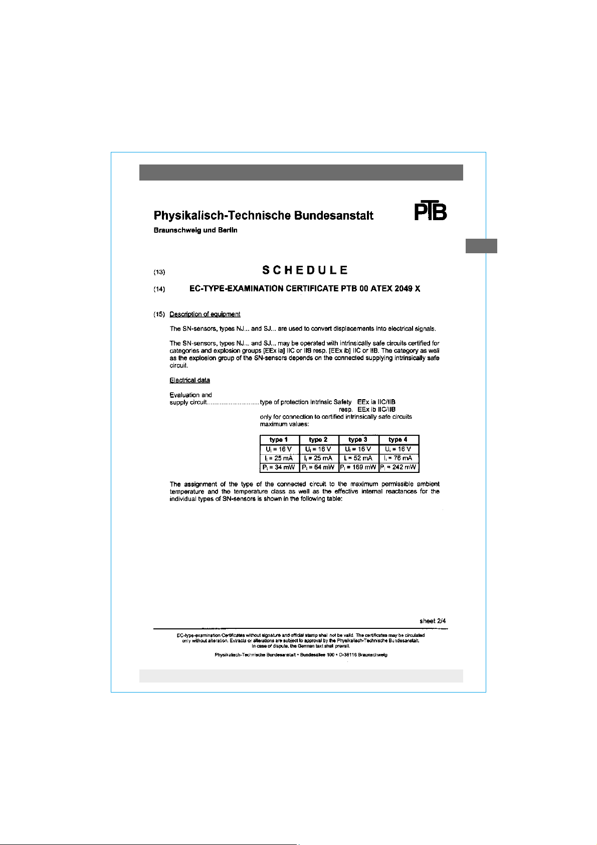
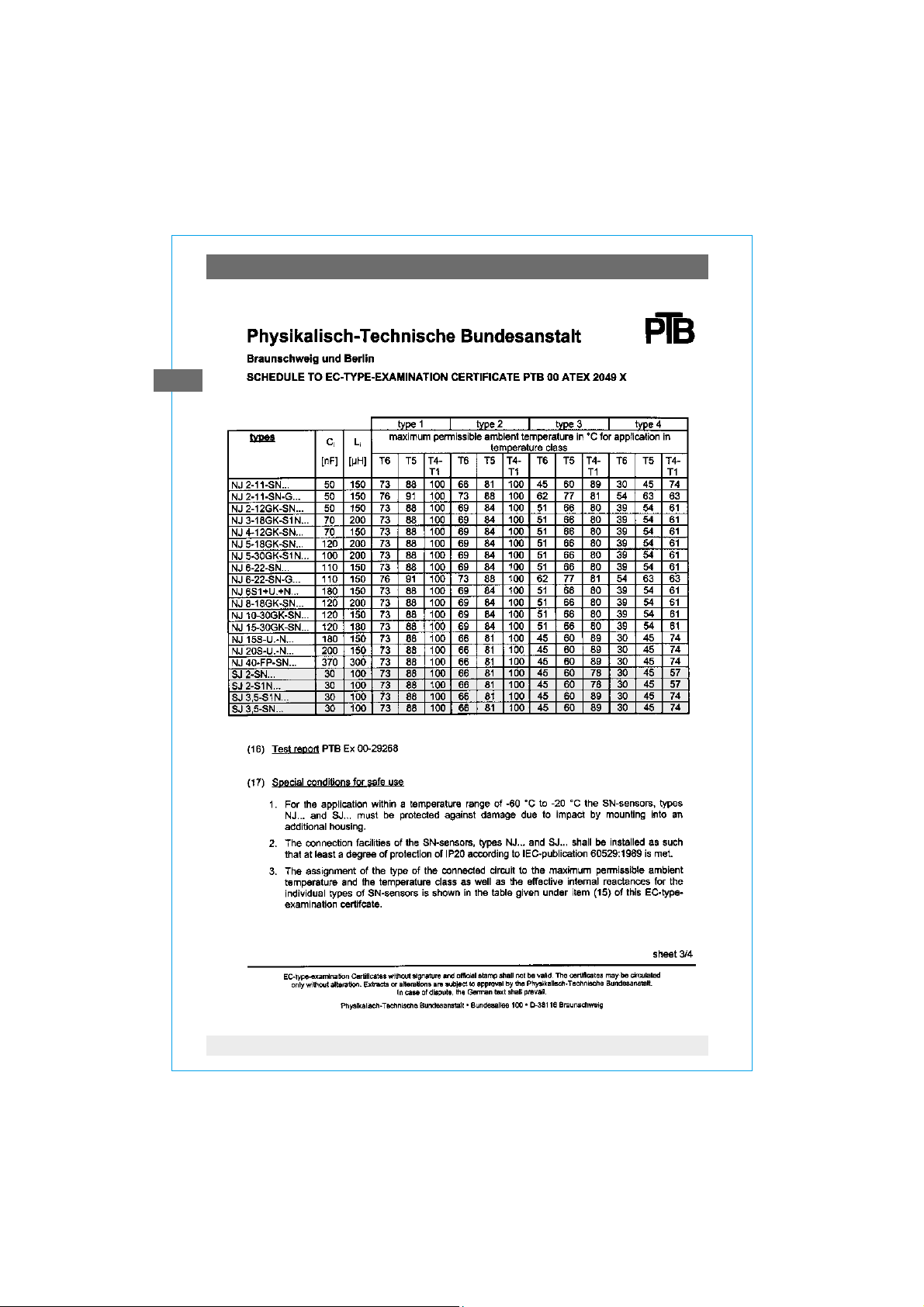
Enclosure 3: EC-type examination certificate (gases)
for SN-sensors types NJ and SJ
(WIKA-Model 831-SN / S1N) 14-17
Enclosure 4: EC-type examination certificate (dust)
for SN-proximity sensors types CB, CC, ... SJ
(WIKA-Model 831 and 831-SN / S1N) 18-22
GB
2030660 12/2004 GB/D/F
3WIKA Operating instructions pressure gauges Model 6 with 831 per ATEX

1. Safety instructions / 2. Description
1. Safety instructions
!
Caution
GB
The appropriate national safety regulations (i.e. VDE 0100 /
EN 60 079-14 / EN 837-2) must be observed when installing,
putting into operation and running these instruments.
T Do not work on gauge while under voltage
T Serious injuries and/or damage can occur should the appropriate
regulations not be observed
€T Only appropriately qualified persons should work on these
instruments
2. Description
T The pressure gauges measure the pressure by means of resilient capsule
measuring elements
T Themeasuring features follow the example of the standards EN 837-3 and
DIN 16 085
The built-in electrical alarm contacts are non-contact slot-type inductive
proximity sensors, which are supplied from control units with circuits that are
certified to be intrinsically safe. When the adjustable set points are reached,
their output circuits will be opened or closed.
T As a standard slot sensors model 831 are used according to EC-type
examination certificate PTB 99 ATEX 2219 X (see enclosure 2) and
ZELM 03 ATEX 0128 X (see enclosure 4)
T SN sensors models 831-SN and -S1N according to PTB 00 ATEX 2049 X
(see enclosure 3) and ZELM 03 ATEX 0128 X (see enclosure 4) are special
designs with safety features (that are not relevant to explosion protection)
for special applications
The connection values of the switches are in accordance with EN 60 947-5-6
("NAMUR").
4 WIKA Operating instructions pressure gauges Model 6 with 831 per ATEX
2030660 12/2004 GB/D/F

3. Technical data and use in accordance with intended use
3. Technical data and use in accordance with intended use
Working pressure
Steady: full scale value
Fluctuating: 0.9 x full scale value
Short time: 1.3 x full scale value (special versions up to 3 × resp.
10 × full scale value)
Pressure connection
T According to the general technical regulations for pressure gauges,
respectively (i.e. EN 837-2 "Selection and installation recommendations for
pressure gauges").
When screw-fitting the gauges the force required for sealing must not be
applied through the case or terminal box but, using a suitable tool, only through
the spanner flats provided for this purpose at the square of the connector.
Installation with
open-end wrench
Temperature effect
GB
When temperature of the pressure element deviates from reference temperature
(+20 °C): max. ±0.6 %/10 K of true scale value
IP Ingress protection
IP 54 per EN 60 529 / IEC 60 529
(with liquid filling IP 65)
2030660 12/2004 GB/D/F
5WIKA Operating instructions pressure gauges Model 6 with 831 per ATEX
3. Technical data and use in accordance with intended use
Operating Temperature
Ambient: -20 ... +60 °C
Attention: Footnote 1) under table 1 must be absolutely taken into account!
GB
Medium: see table 1
Attention! With gaseous substances the temperature may increase as a result
of the compression temperature. In such cases the pressure change rate has to
be slowed down resp. the permissible medium temperature has to be reduced.
Table 1: Permissible medium temperature (only mechanical part)
Ignition temperature of Permissible maximum medium temperature
the ambient atmosphere (in the pressure system)
(temperature class)
> 85 °C (T 6) +70 °C
> 100 °C (T 5) +85 °C
> 135 °C (T 4) +100 °C
> 200 °C (T 3) +100 °C
> 300 °C (T 2) +100 °C
> 450 °C (T 1) +100 °C
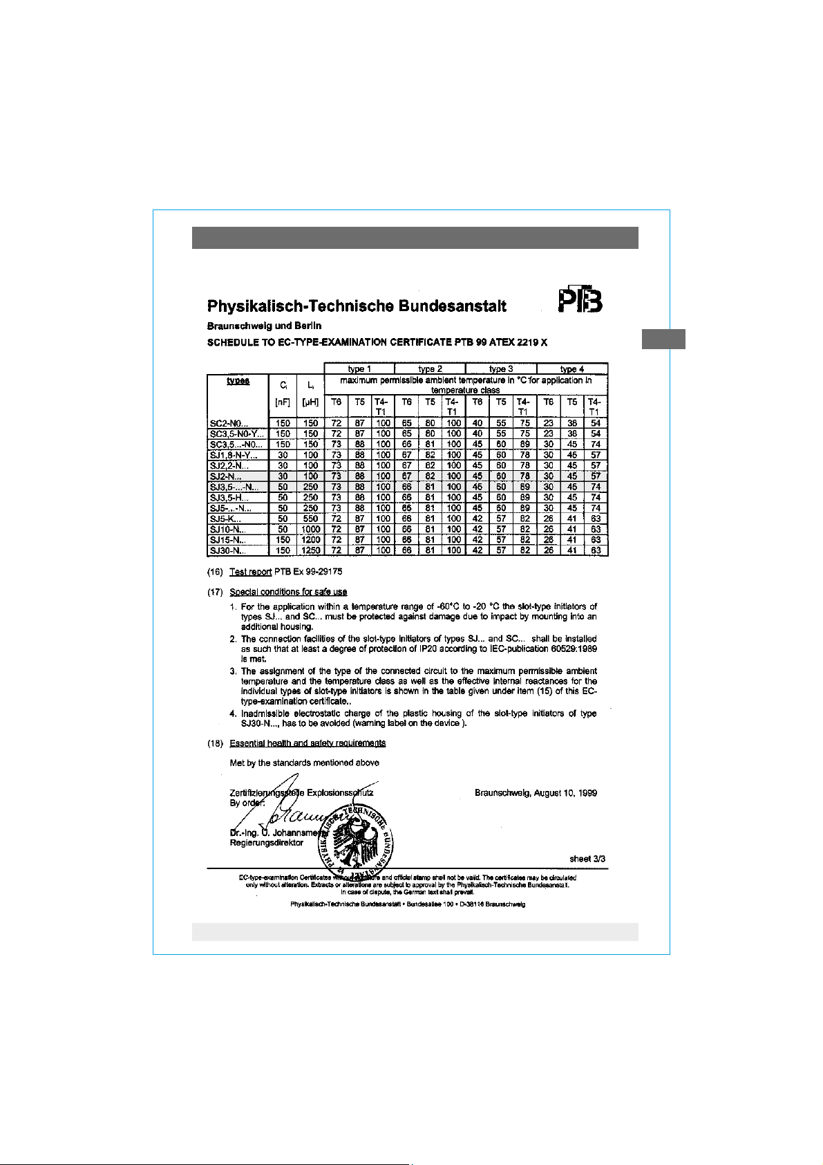
1) The permissible uppper ambient temperature for the electrical components is determined by the
electrical connection values and the ignition temperature of the ambient gases, vapours and dusts.
Therefore the maximum permissible ambient temperatures specified in the EC-type examination
certificates for slot-type sensors and SN sensors must be observed as well. The lower of these two
values is to be considered the maximum permissible ambient temperature!
Materials (wetted parts)
Part Model 612.20 Model 63X.50 Model 614.11 Model 634.11
Pressure connection Cu-alloy stainless steel Cu-alloy stainless steel
Capsule element Cu-alloy stainless steel Cu-alloy stainless steel
Sealing ring NBR FPM NBR FPM
(connection/capsule) (Buna rubber) (Viton) (Buna rubber) (Viton)
6 WIKA Operating instructions pressure gauges Model 6 with 831 per ATEX
2030660 12/2004 GB/D/F

3. Technical data ... / 4. Alarm contacts
Installation
T Nominal position per EN 837-1 / 9.6.7 Figure 9: 90° ( )
T Pressure connection: lower mount (LM) or lower back mount (LBM)
T In order to avoid any additional heating, the instruments must not be
exposed to direct solar irradiation while in operation!
T With filled versions the ventilating valve at the top of the case must be
opened prior to commissioning!
Permissible vibratory stress at the mounting location
T As a matter of principle the instruments should only be mounted at locations
without vibratory stresses
T Where required, a decoupling from the mounting location can be achieved
e.g. by a flexible connecting line from the measuring point to the pressure
gauge and mounting via a measuring instrument bracket.
4. Alarm contacts
EC-type examination certificates
T Standard version Model 831.XX
PTB 99 ATEX 2219 X (enclosure 2) and ZELM 03 ATEX 0128 X (enclosure 4)
Depending on the number of switches and on the case diameter either
Model SJ2-N... or Model SJ3.5-...-N... is used.
T Safety pattern version Models 831.XX - SN or - S1N
PTB 00 ATEX 2049 X (enclosure 3) and ZELM 03 ATEX 0128 X (enclosure 4)
Depending on the number of switches and on the case diameter either
Models SJ 2-SN..., SJ 2-S1N..., SJ 3.5-SN.. or SJ 3.5-S1N... are used.
GB
The built-in sensor type is stated on the product label of the pressure gauge.
Wiring details
T The electrical connections should be made by qualified electricians
T Connection of the switches via screw terminals in the terminal box
2
T Conductor cross section max. 1.5 mm
T The terminal assignment is stated on the connection plate at the
pressure gauge
2030660 12/2004 GB/D/F
7WIKA Operating instructions pressure gauges Model 6 with 831 per ATEX
4. Alarm contacts
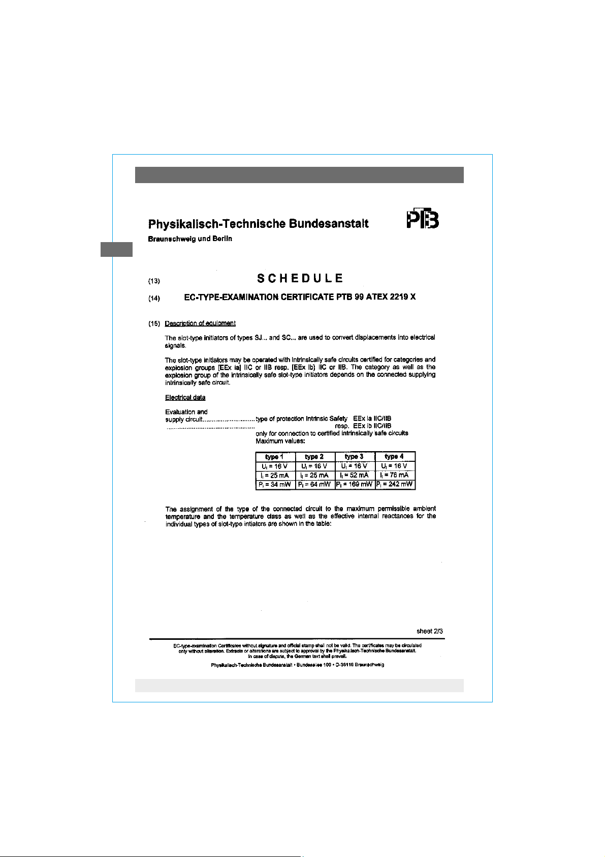
The permissible limits for Ui, Ii and Pi of the intrinsically safe supply circuits
depend on the sensor type. They can be taken from the corresponding EC-type
examination certificates. (The sensor type is stated on the connection plate of
the pressure gauge.)
GB
Suitable switch amplifiers are e.g.:
Circuit Sensor type Model designation EC-type exami- WIKA-
(s. Ex-certific.) Fa. Pepperl & Fuchs nation certificate Model
Model 1 standard KFD2-SR2-Ex1 PTB 00 ATEX 2080 904.31
Model 2 standard KFA6-SR2-Ex1 PTB 00 ATEX 2081 904.28
standard KFD2-SR2 Ex2 PTB 00 ATEX 2080 904.32
standard KFA6-SR2-Ex2 PTB 00 ATEX 2081 904.29
SN-sensors KFD2-SH-Ex1 PTB 00 ATEX 2042 904.33
SN-sensors KHA6-SH-Ex1 PTB 00 ATEX 2043 904.30
Electromagnetic compatibility
EMC according to EN 60 947-5-2.
The instruments are to be protected against strong electromagnetic fields.
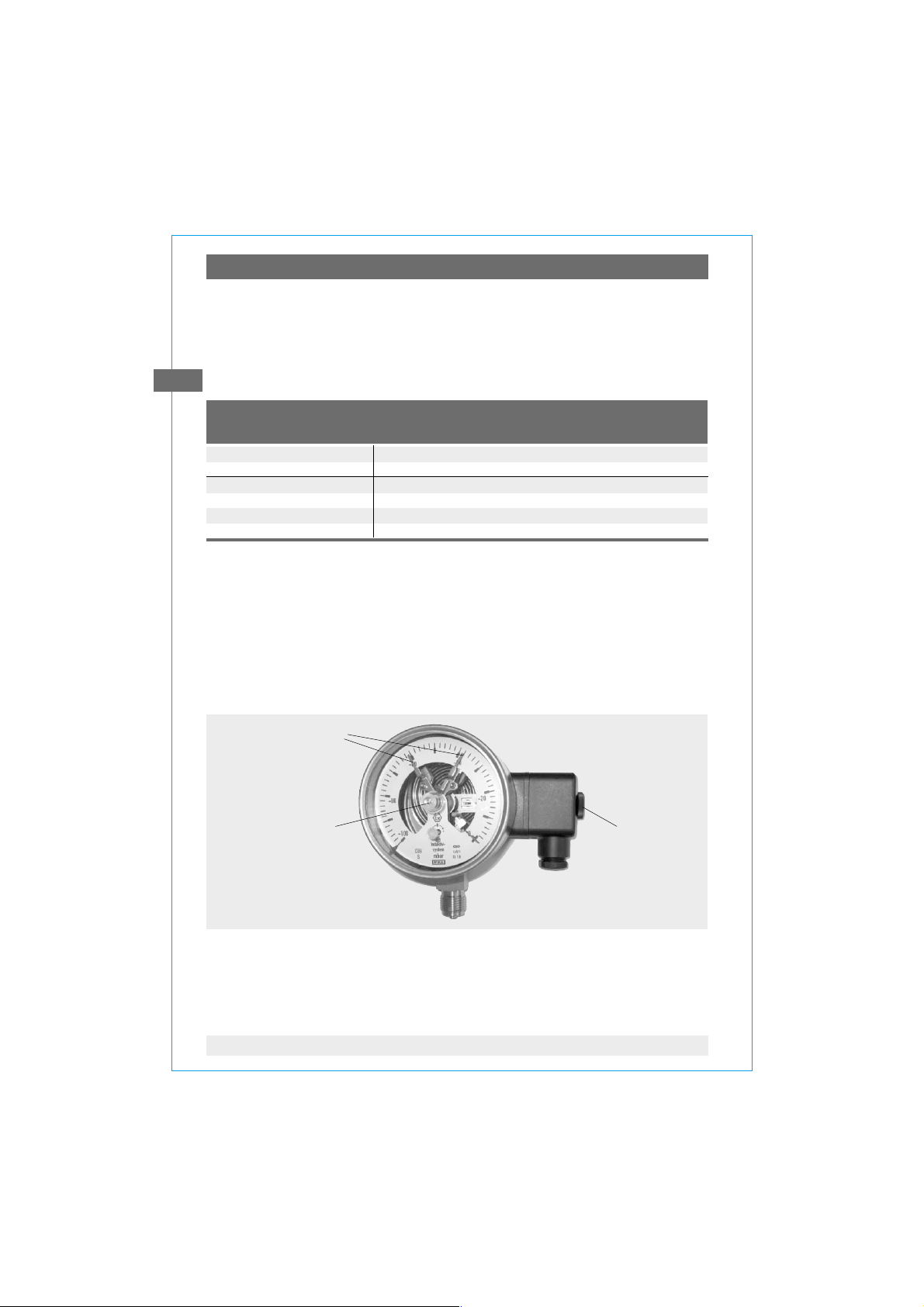
To set desired value indicator
The desired value indicators for the alarm contacts are adjustable over the
adjustment lock in the window with the aid of adjustment key (included in delivery; to be found on standard gauges on the outside edge of the junction box).
Desired value
indicators
(red set pointer)
Adjustment lock
Adjustment key
removable
The desired value indicators for the alarm contacts are adjustable over the full
range of the instrument. Switching points shall be set in the ranges between
10 % und 90 % of the scale, to ensure switching accuracy and long life of the
mechanical measuring system.
8 WIKA Operating instructions pressure gauges Model 6 with 831 per ATEX
2030660 12/2004 GB/D/F

5. Commissioning ... 7. Repairs
5. Commissioning
During the commissioning process pressure peaks must be absolutely avoided.
Open the shut-off valves slowly.
6. Maintenance and servicing / cleaning
The instruments require no maintenance or servicing.
The indicator and switching function should be checked once or twice every
12 months. The instrument must be disconnected from the process to check
with a pressure testing device.
The instruments should be cleaned with a damp cloth moistened with soap
solution. For cleaning inside the instrument the mains power supply should be
disconnected by means of the plug box. It must be ensured that all the parts are
dry before the power is switched on again.
7. Repairs
Repairs are to be only carried out by the manufacturer or appropriately trained
personnel.
For further details see WIKA data sheet AC 08.01 or the data sheet for the
respective basic gauge.
GB
2030660 12/2004 GB/D/F
9WIKA Operating instructions pressure gauges Model 6 with 831 per ATEX
Enclosure 1:
GB
Konformitätserklärung
Richtlinie 94 / 9 / EG (ATEX)
Wir erklären in alleiniger Verantwortung, dass
nachstehend genannte Produkte, Druckmessgeräte
mit Kapselfeder, gemäß gültigem Datenblatt mit der
Richtlinie übere instimmen und dem
Konformitätsbewertungsverfa hren
'Interne Fertigungskontrolle'
unterzogen wurden.
WIKA-Typen / WIKA models
61X.20 / 6XX.50 / 6X4.11
Die Unterlagen werden aufbewahrt
unter der Aktennummer 8000318215
bei der benannten Stelle 0032
TÜV NORD CERT
Am TÜV 1
D-30519 Hannover
Die Geräte werden gekenn zeichnet mit
Angewandte Normen:
EN 13463-1 Grundlagen und Anforderungen
EN 13463-5 Schutz durch konstruktive Sicherheit "c"
Die eingebauten Grenzsignalgeber 831 sind EG-
baumustergeprü ft. Die Nummer n der Prüfbescheinigungen und di e Kennzeichnu ng
PTB 99 AT EX 2219 X bzw./resp. PTB 00 ATEX 2049 X II 2 G EEx ia IIC T6
und/and Z ELM 03 ATEX 012 8 X II 1 D Ex iaD 20 T...°C
WIKA Alexander Wiegand GmbH & Co. KG
MANOMETER AG, Industriestr. 11, CH-6285 Hitzkirch
Hitzkirch, 05.11.2004
Peter Barmettler Daniel Tschopp
Leiter Technik Leiter Qualitätssicherung
Technical Mana ger Quality Assurance Manager
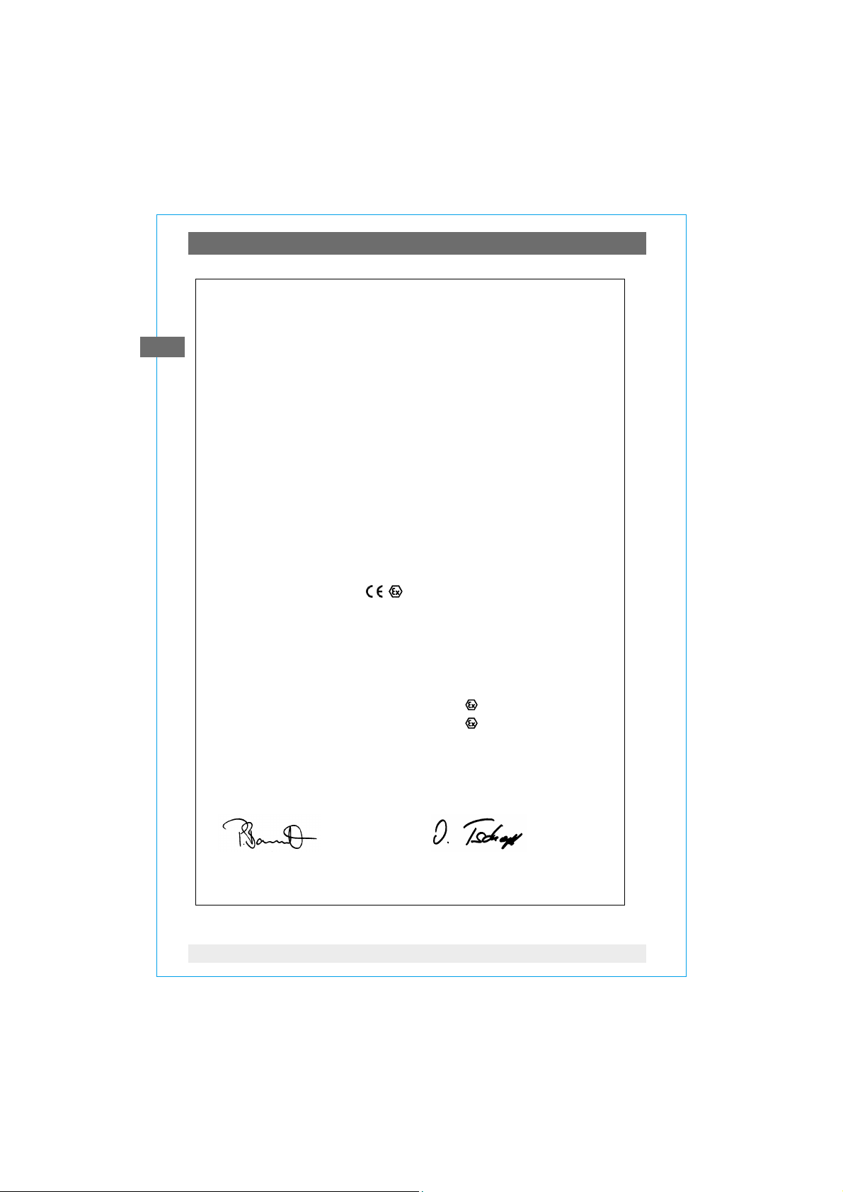
Declaration of Conformity
Directive 94 / 9 / E C (ATEX)
We declare under our sole responsibility that the
products me ntioned below, pressure gauges with
capsule element, according to th e current data sheet
correspond with the directive and were subjected to
the conformity assessment procedure
'Internal Control of Production'.
Datenblätter / da ta sheets
PM 06.02 / PM 06.03 / PM 06.05
The dossier is ret ained
under file nr. 8000318215
at the notified bo dy 0032
TÜV NORD CERT
Am TÜV 1
D-30519 Hannover
The gauges are ma rked with
II 2 GD c
Applied standards:
EN 13463-1 Basic method and requirements
EN 13463-5 Protection by constructional safety "c"
The built-in alarm contacts 831 are EC-type-certified.
Numbers of certificates and marking
10 WIKA Operating instructions pressure gauges Model 6 with 831 per ATEX
2030660 12/2004 GB/D/F
Enclosure 2:
GB
2030660 12/2004 GB/D/F
11WIKA Operating instructions pressure gauges Model 6 with 831 per ATEX
Enclosure 2:
GB
12 WIKA Operating instructions pressure gauges Model 6 with 831 per ATEX
2030660 12/2004 GB/D/F
Enclosure 2:
GB
2030660 12/2004 GB/D/F
13WIKA Operating instructions pressure gauges Model 6 with 831 per ATEX
Enclosure 3:
GB
14 WIKA Operating instructions pressure gauges Model 6 with 831 per ATEX
2030660 12/2004 GB/D/F
Enclosure 3:
GB
2030660 12/2004 GB/D/F
15WIKA Operating instructions pressure gauges Model 6 with 831 per ATEX
Enclosure 3:
GB
16 WIKA Operating instructions pressure gauges Model 6 with 831 per ATEX
2030660 12/2004 GB/D/F

Enclosure 3:
GB
2030660 12/2004 GB/D/F
17WIKA Operating instructions pressure gauges Model 6 with 831 per ATEX

Enclosure 4:
GB
18 WIKA Operating instructions pressure gauges Model 6 with 831 per ATEX
2030660 12/2004 GB/D/F

Enclosure 4:
GB
2030660 12/2004 GB/D/F
19WIKA Operating instructions pressure gauges Model 6 with 831 per ATEX

Enclosure 4:
GB
20 WIKA Operating instructions pressure gauges Model 6 with 831 per ATEX
2030660 12/2004 GB/D/F

Enclosure 4:
GB
2030660 12/2004 GB/D/F
21WIKA Operating instructions pressure gauges Model 6 with 831 per ATEX

Enclosure 4:
GB
22 WIKA Operating instructions pressure gauges Model 6 with 831 per ATEX
2030660 12/2004 GB/D/F

Inhalt
Inhalt
Inhalt
1. Sicherheitshinweise 24
2. Beschreibung 24
3. Technische Daten und bestimmungsgemäße
Verwendung 25
4. Elektrische Grenzsignalgeber 27
5. Inbetriebnahme 29
6. Wartung/Reinigung 29
7. Reparaturen 29
Anlage 1: Konformitätserklärung für Typen 6XX mit
Grenzsignalgeber Typ 831 30
Anlage 2: EG-Baumusterprüfbescheinigung (Gase)
für Schlitzinitiatoren Typen SJ und SC
(WIKA-Typ 831) 31-33
Anlage 3: EG-Baumusterprüfbescheinigung (Gase)
für SN-Sensoren Typen NJ und SJ
(WIKA-Typ 831-SN / S1N) 34-37
Anlage 4: EG-Baumusterprüfbescheinigung (Stäube)
für Näherungssensoren Typen CB, CC, ... SJ
(WIKA-Typ 831 und 831-SN / S1N) 38-42
D
2030660 12/2004 GB/D/F
23WIKA Betriebsanleitung Druckmessgeräte Typ 6 mit 831 nach ATEX

1. Sicherheitshinweise / 2. Beschreibung
1. Sicherheitshinweise
!
Vorsicht
Beachten Sie unbedingt bei Montage, Inbetriebnahme
und Betrieb dieser Geräte die entsprechenden nationalen
Sicherheitsvorschriften (z.B. VDE 0100 / EN 60 079-14 / EN 837-2).
T Alle Arbeiten dürfen nur im spannungslosen Zustand erfolgen
D
T Bei Nichtbeachten der entsprechenden Vorschriften können
schwere Körperverletzungen und / oder Sachschäden auftreten
€T Nur entsprechend qualifiziertes Personal darf an diesen Geräten
arbeiten
2. Beschreibung
T Die Geräte erfassen den zu messenden Druck mit elastischen Kapselfeder-
Messgliedern
T Die messtechnischen Eigenschaften entsprechen den Normen EN 837-3
und DIN 16 085
Die eingebauten elektrischen Grenzwertschalter sind berührungslos arbeitende,
induktive Näherungsschalter in Schlitzbauform, die aus Trennschaltverstärkern
mit bescheinigten eigensicheren Stromkreisen versorgt werden. Bei Überschreiten der einstellbaren Grenzwerte werden deren Ausgangsstromkreise geöffnet
bzw. geschlossen.
T Standard sind die Schlitzinitiatoren Typ 831 entsprechend der
EG-Baumusterprüfbescheinigung PTB 99 ATEX 2219 X (siehe Anlage 2)
und ZELM 03 ATEX 0128 X (siehe Anlage 4)
T Die SN-Sensoren Typ 831-SN bzw. -S1N nach PTB 00 ATEX 2049 X (siehe
Anlage 3) und ZELM 03 ATEX 0128 X (siehe Anlage 4) sind eine Sonderausführung mit (nicht den Explosionsschutz betreffenden) Sicherheitsmerkmalen
für spezielle Anwendungen
Die Anschlusswerte der Schalter entsprechen der EN 60 947-5-6 ("NAMUR").
24 WIKA Betriebsanleitung Druckmessgeräte Typ 6 mit 831 nach ATEX
2030660 12/2004 GB/D/F

3. Technische Daten und bestimmungsgemäße Verwendung
3. Technische Daten und bestimmungsgemäße Verwendung
Verwendungsbereiche
Ruhebelastung: Skalenendwert
Wechselbelastung: 0,9 × Skalenendwert
kurzzeitig: 1,3 × Skalenendwert (Sonderausführungen bis 3 × bzw.
10 × Skalenendwert)
Druckanschluss
T Entsprechend den allgemeinen technischen Regeln für Druckmessgeräte (zB.
EN 837-2 "Auswahl- und Einbauempfehlungen für Druckmessgeräte").
Beim Einschrauben der Geräte darf die zum Abdichten erforderliche Kraft nicht
über das Gehäuse oder die Kabelanschlussdose aufgebracht werden, sondern
mit geeignetem Werkzeug nur über die dafür vorgesehenen Schlüsselflächen am
Vierkant des Anschlusszapfens.
Montage mit
Gabelschlüssel
D
Temperatureinfluss
Bei Abweichung von der Referenztemperatur am Messsystem (+20°C):
max. ±0,6%/10 K vom jeweiligen Skalenwert
IP-Schutzart
IP 54 nach EN 60 529 / IEC 60 529
(mit Flüssigkeitsfüllung IP 65)
2030660 12/2004 GB/D/F
25WIKA Betriebsanleitung Druckmessgeräte Typ 6 mit 831 nach ATEX

3. Technische Daten und bestimmungsgemäße Verwendung
Zulässige Temperaturen
Umgebung: -20 ... +60 °C
Achtung! Unbedingt unter Tabelle 1 die Fußnote 1) berücksichtigen!
Messstoff: siehe Tabelle 1
Achtung! Bei gasförmigen Stoffen kann sich die Temperatur durch Kompressionswärme erhöhen. In solchen Fällen muss ggf. die Druckänderungs-
D
geschwindigkeit gedrosselt bzw. die zulässige Messstofftemperatur reduziert
werden.
Tabelle 1: Zulässige Messstofftemperatur (nur mechanischer Teil)
Zündtempertaur der Zulässige maximale Messstofftemperatur
umgebenden Atmosphäre (im Messsystem)
(Temperaturklasse)
> 85 °C (T 6) +70 °C
> 100 °C (T 5) +85 °C
> 135 °C (T 4) +100 °C
> 200 °C (T 3) +100 °C
> 300 °C (T 2) +100 °C
> 450 °C (T 1) +100 °C
1) Die zulässige obere Umgebungstemperatur für die elektrischen Bauteile wird durch die elektrischen
Anschlusswerte und die Zündtemperatur der umgebenden Gase, Dämpfe bzw. Stäube bestimmt.
Deshalb müssen die in den EG-Baumusterprüfbescheinigungen für die Schlitzinitiatoren bzw. SNSensoren angegebenen höchstzulässigen Umgebungstemperaturen ebenfalls beachtet werden.
Der niedrigere der beiden Werte ist als maximal zulässige Umgebungstemperatur
anzusetzen!
Werkstoffe (messstoffberührte Teile)
Bauteil Typ 612.20 Typ 63X.50 Typ 614.11 Typ 634.11
Druckanschlusszapfen Cu-Legierung CrNi-Stahl Cu-Legierung CrNi-Stahl
Kapselfeder Cu-Legierung CrNi-Stahl Cu-Legierung CrNi-Stahl
Dichtung NBR FPM NBR FPM
(Anschluss/Kapselfeder) (Perbunan) (Viton) (Perbunan) (Viton)
26 WIKA Betriebsanleitung Druckmessgeräte Typ 6 mit 831 nach ATEX
2030660 12/2004 GB/D/F

3. Technische Daten ... / 4. Elektrische Grenzsignalgeber
Installation
T Nennlage nach EN 837-3 / 9.6.6 Bild 9: 90° (
)
T Druckanschlusszapfen unten bzw. rückseitig
T Um zusätzliche Aufheizung zu vermeiden, dürfen die Geräte im Betrieb keiner
direkten Sonneneinstrahlung ausgesetzt werden!
T Falls vorhanden, muss vor Inbetriebnahme das Entlüftungsventil an der
Oberseite des Gehäuses geöffnet werden!
Zulässige Schwingungsbelastung am Einbauort
T Die Geräte dürfen grundsätzlich nur an Stellen ohne Schwingungs-
belastung eingebaut werden
T Gegebenenfalls kann z.B. durch eine flexible Verbindungsleitung von der
Messstelle zum Druckmessgerät und die Befestigung über eine Messgerätehalterung eine Entkopplung vom Einbauort erreicht werden.
4. Elektrische Grenzsignalgeber
EG-Baumusterprüfbescheinigungen
T Standardausführung Typen 831.XX
PTB 99 ATEX 2219 X (Anlage 2) und ZELM 03 ATEX 0128 X (Anlage 4)
Abhängig von der Anzahl der Schalter und vom Gehäusedurchmesser wird
entweder der Typ SJ2-N ... oder der Typ SJ3,5- ... -N ... eingesetzt.
T Sicherheitsausführung Typen 831.XX - SN oder - S1N
PTB 00 ATEX 2049 X (Anlage 3) und ZELM 03 ATEX 0128 X (Anlage 4)
Abhängig von der Schalterzahl und vom Gehäusedurchmesser werden
entweder die Typen SJ 2-SN..., SJ 2-S1N..., SJ 3,5-SN ... oder SJ 3,5-S1N ...
eingesetzt.
D
Der eingebaute Sensortyp ist auf dem Typenschild des Druckmessgerätes
angegeben.
Elektrischer Anschluss
T Der elektrische Anschluss darf nur durch qualifiziertes Personal erfolgen
T Anschluss der Schalter über Schraubklemmen in der Kabeldose
2
T Leitungsquerschnitt max. 1,5 mm
T Klemmenbelegung auf Anschlussschild am Druckmessgerät
2030660 12/2004 GB/D/F
27WIKA Betriebsanleitung Druckmessgeräte Typ 6 mit 831 nach ATEX

4. Elektrische Grenzsignalgeber
Die zulässigen Grenzwerte für Ui, Ii und Pi der eigensicheren Versorgungsstromkreise hängen vom Initiatortyp ab. Sie sind aus den jeweiligen EGBaumusterprüfbescheinigungen zu entnehmen. (Der Initiatortyp ist auf dem
Anschlussschild des Druckmessgerätes angegeben.)
Geeignete Trennschaltverstärker sind z.B.:
Stromkreis Sensortyp Typenbezeichnung EG-Baumuster- WIKA-
D
(s. Ex-Schein) Fa. Pepperl & Fuchs prüfbescheinigung Typ
Typ 1 Standard KFD2-SR2-Ex1 PTB 00 ATEX 2080 904.31
Typ 2 Standard KFA6-SR2-Ex1 PTB 00 ATEX 2081 904.28
Standard KFD2-SR2 Ex2 PTB 00 ATEX 2080 904.32
Standard KFA6-SR2-Ex2 PTB 00 ATEX 2081 904.29
SN-Sensoren KFD2-SH-Ex1 PTB 00 ATEX 2042 904.33
SN-Sensoren KHA6-SH-Ex1 PTB 00 ATEX 2043 904.30
Elektromagnetische Verträglichkeit
EMV gemäß EN 60 947-5-2.
Die Geräte sind vor starken elektromagnetischen Feldern zu schützen.
Einstellen der Sollwertzeiger
Das Einstellen der Sollwerte erfolgt über das Verstellschloss in der Sichtscheibe
mit Hilfe des Verstellschlüssels (gehört zum Lieferumfang; befindet sich bei
Standardgeräten seitlich an der Kabeldose).
Sollwertzeiger
abnehmbarer
Verstellschlüssel
Verstellschloss
Die Sollwertzeiger der Grenzwertschalter sind im gesamten Skalenbereich frei
einstellbar. Aus Gründen der Schaltgenauigkeit und der Lebensdauer der
mechanischen Messsysteme sollen die Schaltpunkte zwischen 10 % und 90 %
der Messspanne liegen.
28 WIKA Betriebsanleitung Druckmessgeräte Typ 6 mit 831 nach ATEX
2030660 12/2004 GB/D/F

5. Inbetriebnahme ... 7. Reparaturen
5. Inbetriebnahme
Bei Inbetriebnahme Druckstöße unbedingt vermeiden, Absperrventile langsam
öffnen.
6. Wartung / Reinigung
Die Geräte sind wartungsfrei.
Eine Überprüfung der Anzeige und der Schaltfunktion sollte etwa 1 bis 2 mal
pro Jahr erfolgen. Dazu ist das Gerät vom Prozess zu trennen und mit einer
Druckprüfvorrichtung zu kontrollieren.
Reinigen der Geräte mit einem (in Seifenlauge) angefeuchteten Tuch.
Zur Reinigung des Innenraums der Kabeldose sind die Leitungen vom Netz zu
trennen. Vor Wiedereinschalten des Stromes ist sicherzustellen, dass alle Teile
abgetrocknet sind.
7. Reparaturen
Reparaturen sind ausschließlich vom Hersteller oder entsprechend geschultem
Personal durchzuführen.
Weitere technische Daten bitte dem WIKA Datenblatt AC 08.01 bzw.
dem Datenblatt des jeweiligen Grundgerätes entnehmen.
D
2030660 12/2004 GB/D/F
29WIKA Betriebsanleitung Druckmessgeräte Typ 6 mit 831 nach ATEX

Anlage 1:
Konformitätserklärung
Richtlinie 94 / 9 / EG (ATEX)
Wir erklären in alleiniger Verantwortung, dass
nachstehend genannte Produkte, Druckmessgeräte
mit Kapselfeder, gemäß gültigem Datenblatt mit der
Richtlinie übere instimmen und dem
Konformitätsbewertungsverfa hren
D
'Interne Fertigungskontrolle'
unterzogen wurden.
WIKA-Typen / WIKA models
61X.20 / 6XX.50 / 6X4.11
Die Unterlagen werden aufbewahrt
unter der Aktennummer 8000318215
bei der benannten Stelle 0032
TÜV NORD CERT
Am TÜV 1
D-30519 Hannover
Die Geräte werden gekenn zeichnet mit
Angewandte Normen:
EN 13463-1 Grundlagen und Anforderungen
EN 13463-5 Schutz durch konstruktive Sicherheit "c"
Die eingebauten Grenzsignalgeber 831 sind EG-
baumustergeprü ft. Die Nummer n der Prüfbescheinigungen und di e Kennzeichnu ng
PTB 99 AT EX 2219 X bzw./resp. PTB 00 ATEX 2049 X II 2 G EEx ia IIC T6
und/and Z ELM 03 ATEX 012 8 X II 1 D Ex iaD 20 T...°C
WIKA Alexander Wiegand GmbH & Co. KG
MANOMETER AG, Industriestr. 11, CH-6285 Hitzkirch
Hitzkirch, 05.11.2004
Peter Barmettler Daniel Tschopp
Leiter Technik Leiter Qualitätssicherung
Technical Mana ger Quality Assurance Manager
Declaration of Conformity
Directive 94 / 9 / E C (ATEX)
We declare under our sole responsibility that the
products me ntioned below, pressure gauges with
capsule element, according to th e current data sheet
correspond with the directive and were subjected to
the conformity assessment procedure
'Internal Control of Production'.
Datenblätter / da ta sheets
PM 06.02 / PM 06.03 / PM 06.05
The dossier is ret ained
under file nr. 8000318215
at the notified bo dy 0032
TÜV NORD CERT
Am TÜV 1
D-30519 Hannover
The gauges are ma rked with
II 2 GD c
Applied standards:
EN 13463-1 Basic method and requirements
EN 13463-5 Protection by constructional safety "c"
The built-in alarm contacts 831 are EC-type-certified.
Numbers of certificates and marking
30 WIKA Betriebsanleitung Druckmessgeräte Typ 6 mit 831 nach ATEX
2030660 12/2004 GB/D/F

Anlage 2:
D
2030660 12/2004 GB/D/F
31WIKA Betriebsanleitung Druckmessgeräte Typ 6 mit 831 nach ATEX

D
Anlage 2:
32 WIKA Betriebsanleitung Druckmessgeräte Typ 6 mit 831 nach ATEX
2030660 12/2004 GB/D/F

Anlage 2:
D
2030660 12/2004 GB/D/F
33WIKA Betriebsanleitung Druckmessgeräte Typ 6 mit 831 nach ATEX

D
Anlage 3:
34 WIKA Betriebsanleitung Druckmessgeräte Typ 6 mit 831 nach ATEX
2030660 12/2004 GB/D/F

Anlage 3:
D
2030660 12/2004 GB/D/F
35WIKA Betriebsanleitung Druckmessgeräte Typ 6 mit 831 nach ATEX

D
Anlage 3:
36 WIKA Betriebsanleitung Druckmessgeräte Typ 6 mit 831 nach ATEX
2030660 12/2004 GB/D/F

Anlage 3:
D
2030660 12/2004 GB/D/F
37WIKA Betriebsanleitung Druckmessgeräte Typ 6 mit 831 nach ATEX

D
Anlage 4:
38 WIKA Betriebsanleitung Druckmessgeräte Typ 6 mit 831 nach ATEX
2030660 12/2004 GB/D/F

Anlage 4:
D
2030660 12/2004 GB/D/F
39WIKA Betriebsanleitung Druckmessgeräte Typ 6 mit 831 nach ATEX

D
Anlage 4:
40 WIKA Betriebsanleitung Druckmessgeräte Typ 6 mit 831 nach ATEX
2030660 12/2004 GB/D/F

Anlage 4:
D
2030660 12/2004 GB/D/F
41WIKA Betriebsanleitung Druckmessgeräte Typ 6 mit 831 nach ATEX

D
Anlage 4:
42 WIKA Betriebsanleitung Druckmessgeräte Typ 6 mit 831 nach ATEX
2030660 12/2004 GB/D/F

Sommaire
Sommaire
Sommaire
1. Conseils de sécurité 44
2. Description 44
3. Caractéristiques techniques et utilisation
correspondante 45
4. Contacts électriques 47
5. Mise en service 49
6. Maintenance/nettoyage 49
7. Réparations 49
Déclaration de Conformité de types 53X avec
contact électrique type 831 (allemand / anglais) 30
Attestation d'examen CE (gaz) pour détecteurs
de proximité à fente des types SJ et SC anglais 11-13
(WIKA-type 831) allemand 31-33
F
Attestation d'examen CE (gaz)
pour détecteurs SN des types NJ et SJ anglais 14-17
(WIKA-type 831-SN / S1N) allemand 34-37
Attestation d'examen CE (poussières) pour détecteurs
de proximité à fente des types CB, CC, ... SJ anglais 18-22
(WIKA-type 831 et 831-SN / S1N) allemand 38-42
2030660 12/2004 GB/D/F
43WIKA Instructions d'utilisation manomètres Type 6 avec 831 selon ATEX

1. Conseils de sécurité / 2. Description
1. Conseils de sécurité
!
Avertissement
F
Les prescriptions de sécurité nationales en vigueur (par exemple
VDE 0100 / EN 60 079-14 / EN 837-2) doivent absolument être
respectées lors du montage, de la mise en service et de
l'utilisation des instruments ici présentés.
T Toutes les interventions doivent être effectuées hors tension
€T Le non-respect des instructions correspondantes est
susceptible d'entraîner des risques de blessure et/ou des
dégâts matériels
€T Seul le personnel habilité et qualifié est autorisé à manipuler
les instruments
2. Description
T Les appareils mesurent la pression par le biais d’un capsule manométrique
à déformation élastique.
T Les caractéristiques techniques de mesure suivent l'exemple des normes
EN 837-3 et DIN 16 085
Les seuils d'alarme électriques intégrés sont des détecteurs de proximité
travaillant sans contact mécanique en forme d'entrefer. Ils sont alimentés par
des relais amplificateurs homologués pour circuits en sécurité intrinsèque. Lors
du dépassement des seuils réglables, les circuits de sortie s'ouvrent ou se
ferment.
T Les détecteurs inductifs standard du type 831 correspondent aux
procédures d'attestation de la conformité PTB 99 ATEX 2219 X (voir annexe 2)
et ZELM 03 ATEX 0128 X (voir annexe 4)
T Les détecteurs SN type 831-SN ou -S1N selon PTB 00 ATEX 2049 X (voir
annexe 3) et ZELM 03 ATEX 0128 X (voir annexe 4) sont une exécution
spéciale (ne concernant pas la protection anti-explosion) avec des attributs
de sécurité pour des utilisations spéciales.
Les valeurs de branchement des contacts correspondent à la EN 60 9475-6
("NAMUR").
44 WIKA Instructions d'utilisation manomètres Type 6 avec 831 selon ATEX
2030660 12/2004 GB/D/F

3. Caractéristiques techniques et utilisation correspondante
3. Caractéristiques techniques et utilisation correspondante
Charge statique: fin d'échelle
Charge dynamique: 0,9 x fin d'échelle
Momentanément: 1,3 x fin d'échelle (exécutions spéciales jusqu'à 3 x ou
Raccord de pression
10 x fin d'échelle)
T Conformément aux règles techniques générales pour les manomètres (par
exemple EN 837-2 "Recommandations sur le choix et l'installation des
manomètres").
Lors de l'opération de vissage des appareils de mesure, la force nécessaire ne
doit pas être appliquée sur le boîtier ou sur la prise câblée, mais seulement sur
les surfaces prévues par un outil approprié sur le carré du raccord.
Montage avec
clef à molette
Influence de la température
En cas de divergence de la température de référence (+20°C)
sur l'organe moteur: max. ±0,6 %/10 K de la fin d'échelle respective
IP Degré de protection
IP 54 selon EN 60 529 / IEC 60 529
(avec bain amortisseur IP 65)
F
2030660 12/2004 GB/D/F
45WIKA Instructions d'utilisation manomètres Type 6 avec 831 selon ATEX

3. Caractéristiques techniques et utilisation correspondante
Températures autorisées
Ambiante: -20 °C ... +60 °C
Attention! Absolument prendre en considération la note de bas de page 1)
en dessous du tableau 1.
Fluide: voir tableau 1
Attention! Pour les fluides gazeux la température peut s'élever par le biais
d'une température de compression. Dans ces cas il faut, soit limiter la vitesse
d'élévation de la pression, soit réduire la température de fluide admissible.
F
Tableau 1: Température de fluide admissible (uniquement pour la partie
mécanique)
Température d'inflammation Température maximale autorisée du fluide
de l'atmosphère environnante (dans le système de mesure)
(Classe de température)
> 85 °C (T 6) +70 °C
> 100 °C (T 5) +85 °C
> 135 °C (T 4) +100 °C
> 200 °C (T 3) +100 °C
> 300 °C (T 2) +100 °C
> 450 °C (T 1) +100 °C
1) La valeur supérieure de la température ambiante admissible pour les composants électriques
est déterminée par les valeurs électriques de branchement et la température d'inflammation
des gaz, vapeurs ou poussières environnants. Par conséquent, il faut respecter également
les valeurs de températures ambiantes maximales pour les détecteurs à entrefer ou
détecteurs SN comme décrits dans les procédures d'attestation de la conformité CE.
La valeur la plus basse des deux est à utiliser comme température ambiante
maximale admissible!
Matériaux (parties en contact avec le fluide)
Partie Type 612.20 Type 63X.50 Type 614.11 Type 634.11
Raccordement alliage de cuivre acier inox alliage de cuivre acier inox
Capsule alliage de cuivre acier inox alliage de cuivre acier inox
Joint NBR FPM NBR FPM
(Raccord/capsule) (Perbunan) (Viton) (Perbunan) (Viton)
46 WIKA Instructions d'utilisation manomètres Type 6 avec 831 selon ATEX
2030660 12/2004 GB/D/F

3. Caractéristiques techniques ... / 4. Contacts électriques
Installation
T Position de base selon EN 837-1 / 9.6.7. image 9: 90° ( )
T Raccord pression vertical ou arrière
T Afin d'éviter un échauffement additionnel en fonctionnement, les
appareils ne doivent pas être exposés aux rayons solaires!
T Pour les appareils remplis de liquide il faut, avant la mise en service,
ouvrir le dispositif de mise à l’atmosphère se trouvant au sommet du boîtier!
Contrainte de vibration admissible sur le point de montage
T Les appareils ne devraient en principe être installés que sur des applications
exemptes de vibrations
T Le cas échéant, on peut atteindre un découplage du point de mesure
en utilisant une liaison flexible au manomètre et en le fixant à l'aide
d'un support d'appareil mural.
4. Contacts électriques
Attestation d'examen CE
T Exécution standard types 831.XX
PTB 99 ATEX 2219 X (annexe 2) et ZELM 03 ATEX 0128 X (annexe 4)
En fonction du nombre de contacts et du diamètre du boîtier on
utilise soit le type SJ2-N…, soit le type SJ3,5- … -N
T Exécution de sécurité types 831.XX - SN ou - S1N
PTB 00 ATEX 2049 X (annexe 3) et ZELM 03 ATEX 0128 X (annexe 4)
En fonction du nombre de contacts et du diamètre du boîtier on
utilise soit les types SJ 2-SN..., SJ 2-S1N..., SJ 3,5-SN ..., soit SJ 3,5-S1N ...
Le type de détecteur intégré est indiqué sur la plaquette d'identification
du manomètre.
Raccords électriques
T Les travaux de raccordement électrique ne doivent être effectués que par
des ouvriers qualifiés pour ce faire
F
T Le branchement des contacts se fait bar des bornes dans la boîte de jonction.
2
T La section des conducteurs est de maxi 1,5 mm
T La codification des borniers se trouve sur la plaquette de branchement de
l'appareil.
2030660 12/2004 GB/D/F
47WIKA Instructions d'utilisation manomètres Type 6 avec 831 selon ATEX

4. Contacts électriques
Les valeurs limites autorisées pour Ui, li et Pi de l'alimentation intrinsèque
des circuits dépendent du type de détecteur. Ces valeurs sont indiquées
dans les procédures d'attestation de la conformité CE. (Le type de détecteur
est indiqué sur le schéma de branchement du manomètre).
Exemple pour relais d'amplification appropriés:
Circuit Type de Code de désignation Attestation Type
(voir fiche Ex) détecteur Etbs. Pepperl & Fuchs d'examen CE WIKA
Type 1 Standard KFD2-SR2-Ex1 PTB 00 ATEX 2080 904.31
F
Type 2 Standard KFA6-SR2-Ex1 PTB 00 ATEX 2081 904.28
Standard KFD2-SR2 Ex2 PTB 00 ATEX 2080 904.32
Standard KFA6-SR2-Ex2 PTB 00 ATEX 2081 904.29
SN-Sensoren KFD2-SH-Ex1 PTB 00 ATEX 2042 904.33
SN-Sensoren KHA6-SH-Ex1 PTB 00 ATEX 2043 904.30
Compatibilité électromagnétique
CEM selon EN 60 947-5-2.
Les appareils sont à protéger contre de forts champs électromagnétiques.
Réglage de l'indicateur de la valeur de consigne
Le réglage des valeurs de consigne s'effectue au moyen via le trou de réglage
dans le cadran à l'aide de la clef de réglage (fournie avec l'appareil, elle se
trouve, dans les modèles standard, sur le côté dans la boîte à câble).
Indicateur de
la valeur
de consigne
Trou de réglage
Clef de
réglage
amovible
Les indicateurs de valeur de consigne des seuils peuvent être réglés librement
sur toute l'échelle de mesure. Pour des raisons de précision et de sécurité de
commutation, et afin de ne pas porter préjudice à la durée de vie des appareils,
il est recommander de fixer les points de commutation entre 10 % et 90 % de
l'écart de mesure.
48 WIKA Instructions d'utilisation manomètres Type 6 avec 831 selon ATEX
2030660 12/2004 GB/D/F

5. Mise en service ... 7. Réparations
5. Mise en service
Lors de la mise en service il faut absolument éviter les coups de bélier. Ouvrir
lentement les vannes de fermeture.
6. Maintenance / Nettoyage
Les instruments ne requièrent aucune maintenance.
Un contrôle de l'affichage et des fonctions de commande est recommandé 1 à
2 fois/an. Pour le contrôle de l'affichage et des fonctions de commande, il faut
isoler l'appareil du processus de mesure et le contrôler avec un dispositif de
contrôle de pression.
Nettoyer les instruments avec un chiffon légèrement humidifié avec de l'eau et
du savon de Marseille). Avant de rebrancher l'instrument, s'assurer que toutes
les pièces soient complètement sèches.
Pour le nettoyage de l'intérieur de la boîte de jonction, il est nécessaire
de séparer les conducteurs du secteur.
7. Réparations
Toute réparation doit être exclusivement confiée au fabricant ou au personnel
qualifié correspondant.
Pour autres données, se reporter à la fiche type WIKA AC 08.01 ou à la fiche
technique de l'instrument correspondant.
F
2030660 12/2004 GB/D/F
49WIKA Instructions d'utilisation manomètres Type 6 avec 831 selon ATEX

50 WIKA Betriebsanleitung Druckmessgeräte Typ 6 mit 831 nach ATEX
2030660 12/2004 GB/D/F

WIKA Global
Europe/Middle East/Africa
Austria
WIKA-Messgerätevertrieb
Ursula Wiegand GmbH & Co. KG
Tel.: 0043/1/869 16 31
E-Mail: info@wika.at
Benelux / Netherlands
WIKA Benelux
Tel.: 0031/475/53 55 00
E-Mail: info@wika.nl
Finland
WIKA Finland Oy
Tel.: 00358/9/682 49 20
E-mail: wika@wika.fi
France
WIKA Instruments s.a.r.l.
Tel.: 0033/1/34 30 84 84
E-Mail: info@wika-instruments.fr
Germany
WIKA Alexander Wiegand GmbH & Co. KG
Tel.: 0049/9372/132-0
E-Mail: info@wika.de
Italy
WIKA Italiana S.r.l.
Tel.: 0039/02/93 97 00 1
E-Mail: info@wika.it
Russia
ZAO „WIKA MERA“
Tel.: 007-503-234 44 32
E-Mail: info@wika.ru
Kazakhstan
TOO WIKA Kasachstan
Tel.: 007-3272-925 638
E-Mail: wika-kazakhstan@nursat.kz
South Africa
WIKA Instruments (Pty.) Ltd.
Tel.: 0027/11/621 00 00
E-Mail: sales@wika.co.za
Spain
Instrumentos WIKA S.A.
Tel.: 0034/93/746 44 45
E-Mail: info@wika.es
Switzerland
Manometer AG
Tel.: 0041/41/919 72 72
E-Mail: info@manometer-ag.ch
United Arab Ermirates
WIKA Middle East FZE
Tel.: 00971/4/88 90 90
E-Mail: wikame@emirates.net.ae
United Kingdom
WIKA Instruments Limited
Tel.: 0044/208/763 60 00
E-Mail: info@wika.co.uk
2030660 12/2004 GB/D/F
America
Argentina
WIKA Argentina S.A.
Tel.: 005411/4730/1800
E-Mail: info@wika.com.ar
Brazil
WIKA do Brasil Industria e Comercio
Tel.: 0055/152/66 16 55
E-Mail: wika@splicenet.com.br
Canada
WIKA Instruments Ltd.
Tel: 001/780/463-7035
E-Mail: info@wika.ca
U.S.A.
WIKA Instrument Corporation
Tel.: 001/770/513 82 00
E-Mail: info@wika.com
Asia/Pacific
Australia
WIKA Australia Pty. Ltd.
Tel.: 0061/3/98 70 06 66
E-Mail: sales@wika.com
China
WIKA Instrumentation
Tel.: 0086/512/825 80 67
E-Mail: wikainst@public1.sz.js.cn
India
WIKA Instruments India Pvt. Ltd.
Tel.: 0091-20-68 20 31
E-Mail: wika@pn2.vsnl.net.in
Indonesia
WIKA Indonesia
Tel.: 0062/21/55 95 21 52
E-Mail: handie@indo.net.id
Japan
WIKA JAPAN K. K.
Tel.: 0081/-3-5777-0589
E-Mail: m-gawronski@wika.co.jp
Korea
WIKA Korea Ltd.
Tel.: 0082-2-869-0505
E-Mail: info@wika.co.kr
Malaysia
WIKA Malaysia
Tel. 00 60-3-46 13 355
E-Mail: ktsee@tm.net.my
Singapore
WIKA Singapur
WIKA Instrumentation Pte Ltd
Tel.: 0065 - 8445506
51WIKA Betriebsanleitung Druckmessgeräte Typ 6 mit 831 nach ATEX

Technical alteration rights reserved.
Technische Änderungen vorbehalten.
Sous réserve de modifications techniques.
WIKA Alexander Wiegand GmbH & Co. KG
Alexander-Wiegand-Straße 30
63911 Klingenberg € Germany
Phone (+49) 93 72/132-0
Fax (+49) 93 72/132-406
E-Mail info@wika.de
www.wika.de
MANOMETER AG
Industriestrasse 11
6285 Hitzkirch € Switzerland
Phone (+41) 41-919 72 72
Fax (+41) 41-919 72 73
E-mail info@manometer.ch
www.manometer.ch
52 WIKA Betriebsanleitung Druckmessgeräte Typ 6 mit 831 nach ATEX
2030660 12/2004 GB/D/F
 Loading...