

Page 1
Operating instructions
Cryo Gauge
Betriebsanleitung
Mode d'emploi
Manuale d'uso
Dierential pressure gauge
Models 712.15.100, 732.15.100
Dierenzdruckmessgerät
Typen 712.15.100, 732.15.100
Manomètre pour pression diérentielle
Types 712.15.100, 732.15.100
Manometro dierenziali
Modelli 712.15.100, 732.15.100
GB
D
F
I
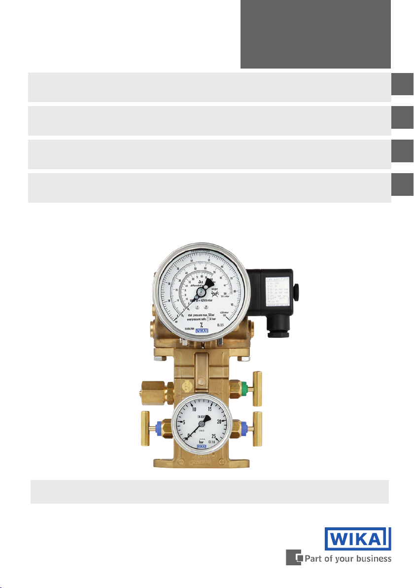
Model 712.15.100 with optional transmitters for dierential
pressure and working pressure
Page 2

Operating instructions for dierential pressure gauges
GB
Models 712.15.100, 732.15.100 Page 3-19
Betriebsanleitung für Dierenzdruckmessgeräte
D
Typen 712.15.100, 732.15.100 Seite 21-37
Mode d’emploi pour manomètres pour pression diérentielle
F
Types 712.15.100, 732.15.100 Page 35-47
Manuale d‘uso per manometri dierenziali
I
Modelli 712.15.100, 732.15.100 Pagine 53-66
© 2010 WIKA Alexander Wiegand SE & Co. KG
All rights reserved. / Alle Rechte vorbehalten.
®
WIKA
is a registered trademark in various countries.
®
WIKA
ist eine geschützte Marke in verschiedenen Ländern.
Prior to starting any work, read the operating instructions!
Keep for later use!
Vor Beginn aller Arbeiten Betriebsanleitung lesen!
Zum späteren Gebrauch aufbewahren!
Lire le mode d'emploi avant de commencer toute opération !
A conserver pour une utilisation ultérieure !
Prima di iniziare ad utilizzare lo strumento, leggere il manuale d‘uso!
Conservare per future consultazioni!
2
WIKA operating instructions dierential pressure gauge models 712.15.100, 732.15.100
11592011.04 06/2014 GB/D/F/I
Page 3
Contents
Contents
1. Safety 4
2. General information 4
3. Installation 4
4. Dierential pressure gauge 6
5. Valve manifold with working pressure gauge (optional) 8
6. Application note 9
7. Adapter for process connection (optional) 9
8. Transmitter for level measurement (optional) 9
9. Transmitter for working pressure indication (optional) 13
10. Switch contacts (optional) 14
11. Maintenance 16
GB
12. Disposal 16
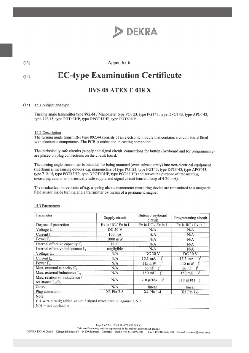
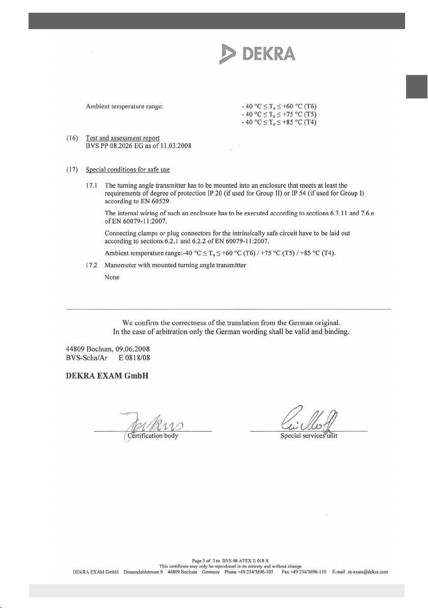
Enclosure 1: EC-type examination certicate (Ex approval)
for turning angle transmitter type 892.44 17
Information
This symbol provides you with information, notes and
tips.
Warning!
This symbol warns you against actions that can cause
injury to people or damage to the instrument.
11592011.04 06/2014 GB/D/F/I
WIKA operating instructions dierential pressure gauge models 712.15.100, 732.15.100
3
Page 4

1. Safety ... 3. Installation
1. Safety
GB
WARNING!
Before installation, commissioning and operation, ensure that the
appropriate dierential pressure gauge has been selected in terms of
measuring range, design and specic measuring conditions.
Only work on the gauge with the voltage disconnected.
Non-observance can result in serious injury and/or damage to equipment.
Only appropriately qualied skilled personnel should work on these
instruments.
2. General information
These operating instructions are based upon the following:
EN 837-2: Selection and installation recommendations for pressure gauges
Data sheet PM 07.29: Dierential pressure gauges models 712.15.100, 732.15.100
Data sheet PM 02.01, PM 02.02: Bourdon tube pressure gauges
3. Installation
The installation of the dierential pressure gauge should be carried out in accordance with the
installation recommendations for pressure gauges per EN 837-2 /7.
Prior to the installation of the pressure gauge, the pipes should be thoroughly cleaned
The pressure gauge should be installed and operated such as to avoid exposure to
vibration.
Mounting by means of - rigid tailpipe and/or
- 4 M8 threaded mounting holes incorporated in the body
The pressure gauges should be protected against contamination and high temperature
uctuations
The maximum permissible media/ambient temperature must not be exceeded
Fitting of the pressure connections as per the j and i symbols
j
higher pressure ⇒ bottom pressure (p
i
lower pressure ⇒ working pressure/overriding pressure (p
p
= pFL + p
B
D
),
B
)
D
(with pFL = hydrostatic pressure of liquid = ρ • g • h)
4
WIKA operating instructions dierential pressure gauge models 712.15.100, 732.15.100
11592011.04 06/2014 GB/D/F/I
Page 5
3. Installation
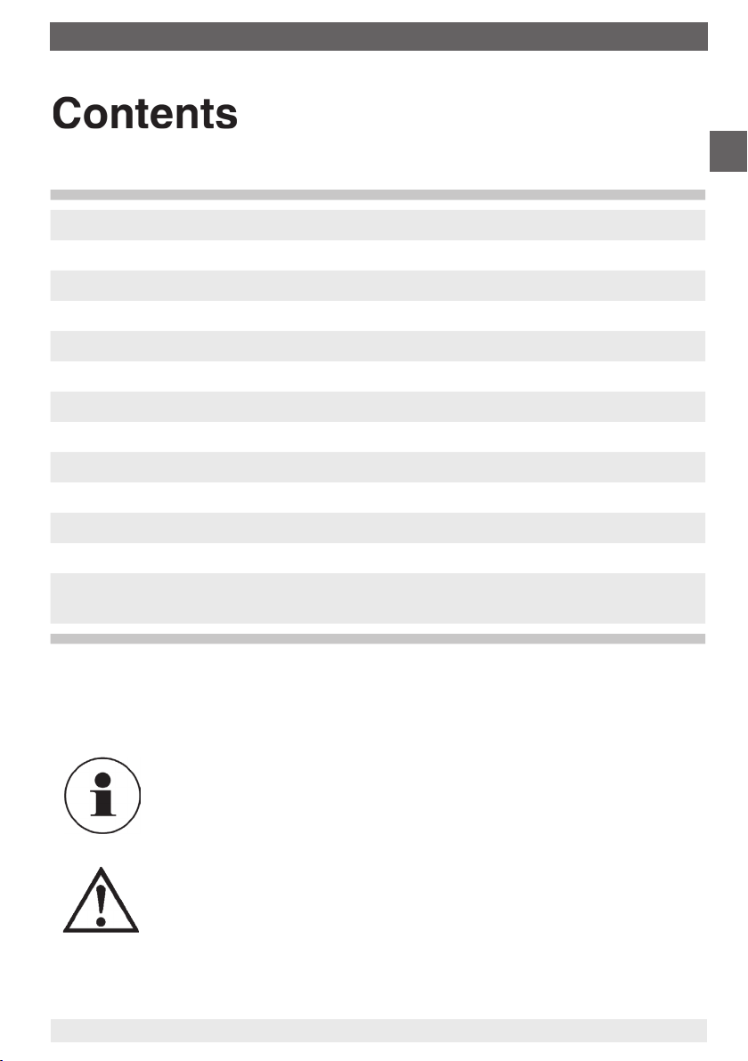
Types of installation for level measurement
Standard in cryogenic equipment 2 examples with condensate formation
(liquid gases)
Filling hole
p
D
Δp Δp Δp
p
D
p
B
p
D
Drain pipe Drain pipe
p
B
i ji j
Condensate
Filling
hole
p
D
Condensate
⇔
Constant
level
vessel
i j
Wall mounting
Installation/fastening to the 4 mounting holes M8 / 2 xing holes Ø 8.5
Mounting holes M8
Filling
hole
p
D
hhh
Drain pipe
Pressure
connections G 1/4
GB
Pressure
equalising valve
Isolating valve
j
Ø 8.5 xing h oles
Pressure connections G 1/4
11592011.04 06/2014 GB/D/F/I
WIKA operating instructions dierential pressure gauge models 712.15.100, 732.15.100
Tes t
connection
Isolating
valve
i
11592649.01
5
Page 6
3. Installation / 4. Dierential pressure gauge
Option
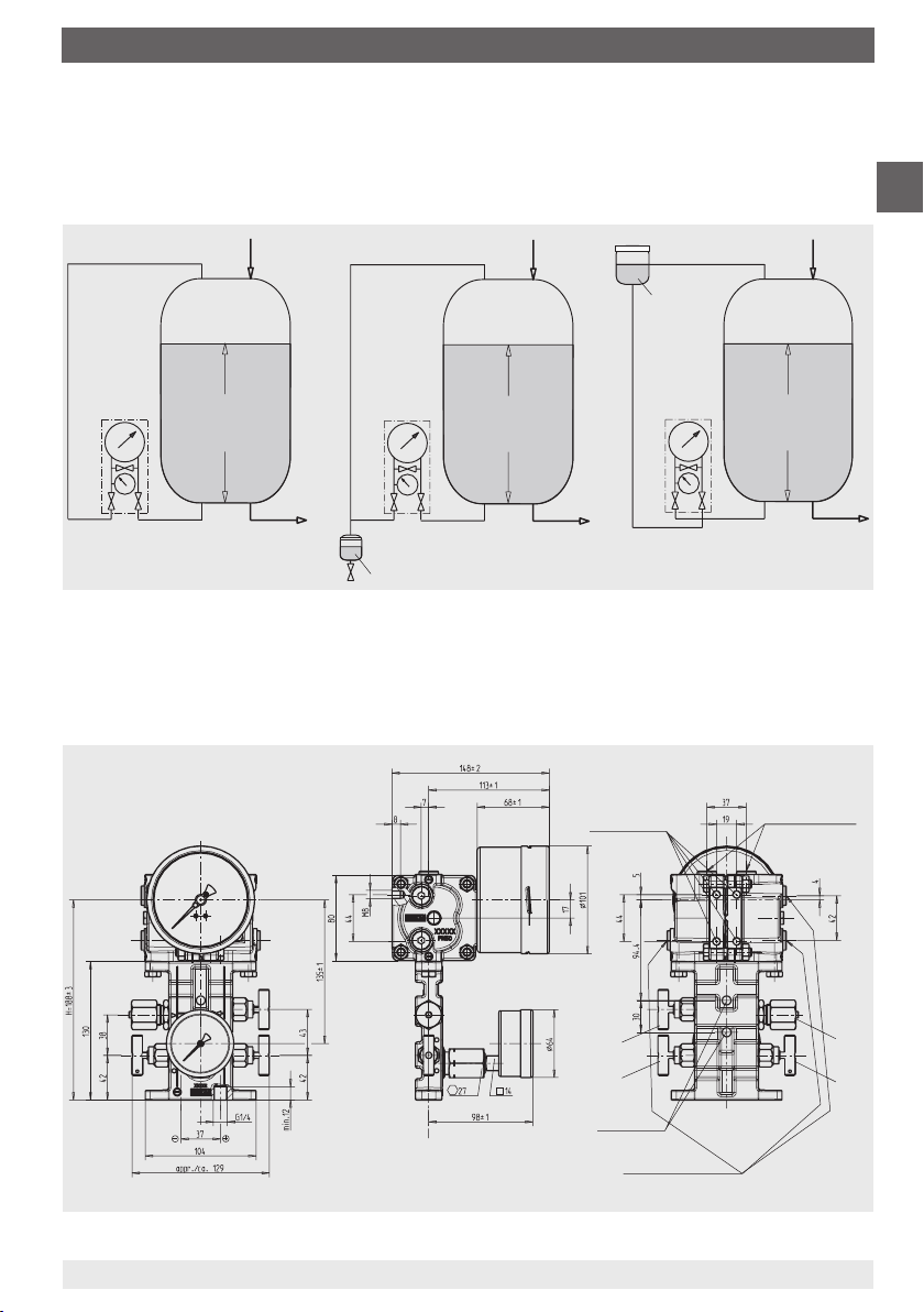
Panel mounting
GB
Panel cut-out
Panel
4. Dierential pressure gauge
The measuring range of the dierential pressure gauge can, depending on the particular
measurement system used, be adjusted within the limits given in the previous specications
table). Ideally, this adjustment should be made on a test bench, though it can also be carried
out at the measuring point using a hand test pump.
11563843.01
Measuring range limits
Measuring cell Adjustable measuring ranges
from to
60 mbar 0 ... 40 mbar - 0 ... 60 mbar
90 mbar 0 ... 60 mbar - 0 ... 90 mbar
120 mbar 0 ... 80 mbar - 0 ... 120 mbar
165 mbar 0 ... 110 mbar - 0 ... 165 mbar
240 mbar 0 ... 160 mbar - 0 ... 240 mbar
330 mbar 0 ... 220 mbar - 0 ... 330 mbar
480 mbar 0 ... 320 mbar - 0 ... 480 mbar
660 mbar 0 ... 440 mbar - 0 ... 660 mbar
975 mbar 0 ... 650 mbar - 0 ... 975 mbar
1,350 mbar 0 ... 900 mbar - 0 ... 1,350 mbar
1,725 mbar 0 ... 1,150 mbar - 0 ... 1,725 mbar
6
WIKA operating instructions dierential pressure gauge models 712.15.100, 732.15.100
11592011.04 06/2014 GB/D/F/I
Page 7
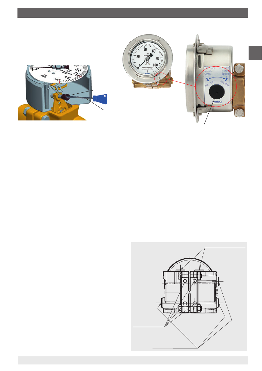
Adjustable measuring span
Adjustable measuring
span
Allen key
(included in delivery)
GB
Turn clockwise: reduce measuring range
Turn anticlockwise: expand measuring range
Cover cap for adjustable
measuring span
1. The span adjustment, situated at the ‚4 o‘clock‘ point on the instrument case, is accessible
through the case by removing the cover cap.
2. Charge the instrument to the desired nominal pressure.
3. To set the pointer to the span value, using an allen key (size 3 mm) inserted into the
funnel, turn it either clockwise (reduce the measuring range) or anticlockwise (expand the
measuring range). The gauge will then be fully adjusted to the required measuring range.
4. If the gauge is equipped with a transmitter model 89x.44 (see page 9), then this procedure
will also adjust the output signal to the new measuring range.
5. After completing the adjustment the equipment should be resealed with the cover cap.
Additional pressure connections
G 1/4 pressure connections
Three additional G ¼ female threads are
available on the minus measurement
chamber (the right measuring cell ange
when viewed from the back) e.g. for
connecting a pressure switch, safety
valve or A-10 Cryo or IS-20 transmitters
Two G ¼ female threads are available on
the plus measurement chamber (the left
cell ange when viewed from the back)
e.g. for recalibration
11592011.04 06/2014 GB/D/F/I
WIKA operating instructions dierential pressure gauge models 712.15.100, 732.15.100
Mounting holes
M8
G 1/4 pressure connections
11557711.01AB
7
Page 8
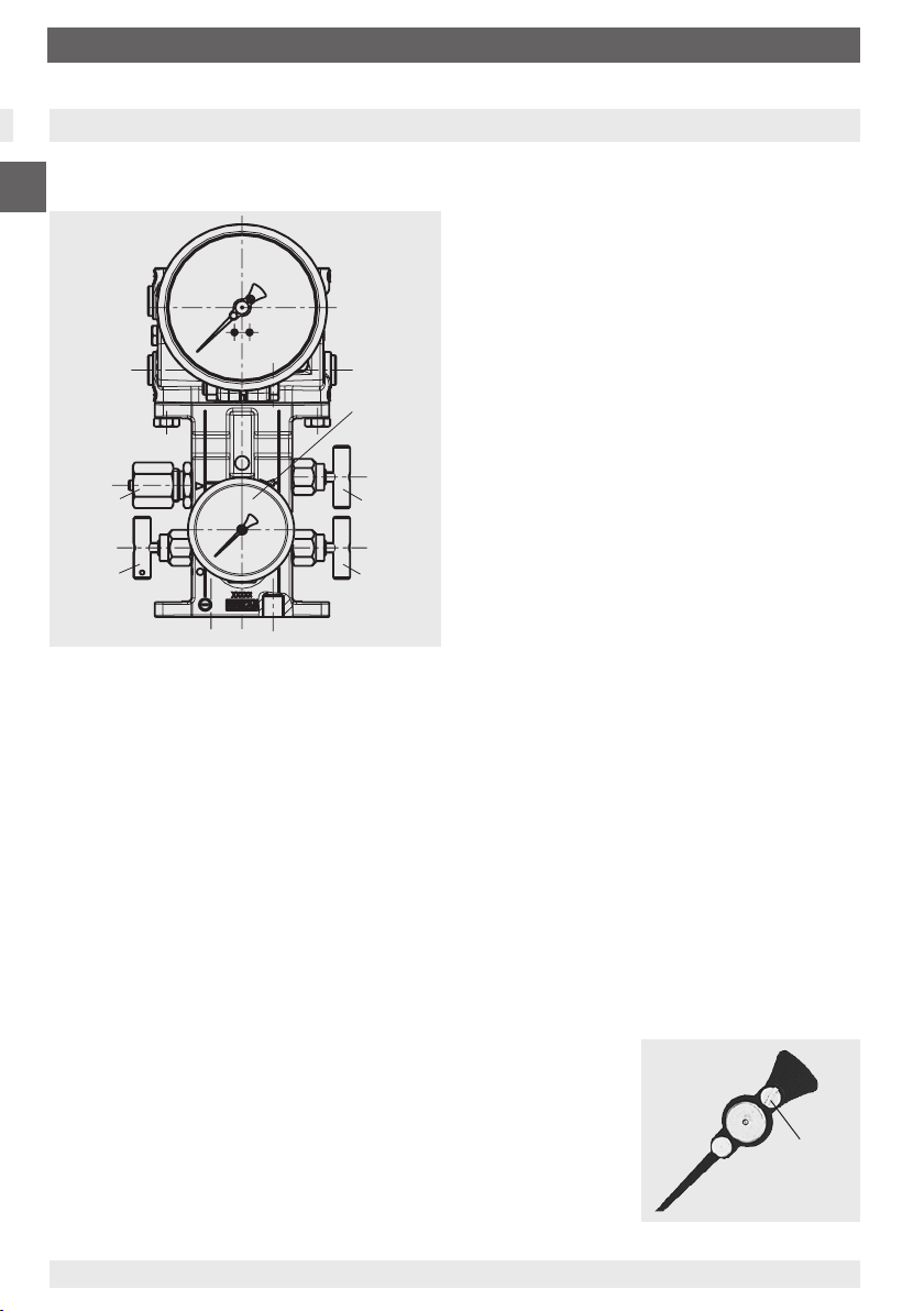
5. Valve manifold with working pressure gauge (optional)
5. Valve manifold with working pressure gauge (optional)
The compact optional anged valve manifold for an NG 63 working pressure gauge allows the
central measurement of level and working pressure in a single device.
GB
To isolate line pressures without inter-
rupting the process, enabling gauge
removal/examination and protecting the
gauge against overpressure of n-times
rated pressure which may occur during
plant pressure testing.
11592649.01AB
To protect the gauge against pressure
surges/pressure spikes, and thus against
Working
Test connection
M20 x 1.5
Isolating valve
i
pressure gauge
NS 63
Pressure
equalising
valve
Isolating valve
j
-
c) Connect the pressure standard and test pump using the additional G ¼ female port in the
plus chamber of the measuring system
d) Remove the test connection screw from the minus side valve manifold
e) The plus side can then be pressurised
f) After adjustment:
- Close the air bleed screw
- Disconnect the pressure standard and test pump and close the connection
- Slowly open rst the plus and then the minus shut-o valve
Test connection M20 x 1.5 for checking the working pressure gauge
The pressure equalising valve allows a zero point control during operation (with open valve).
a) Close the plus and minus shut-o valve
b) Afterwards open the pressure equalising valve
While the media is owing from the higher pressure side to the other side, the dierential
pressure at the pressure gauge drops to zero (the dierential pressure display must be at
zero, i.e. within the zero tolerance range which shows that the gauge is
A zero adjustment can be made using the standard integra-
ted, adjustable pointer (remove snap t bezel incl. window and
sealing ring beforehand). Twisting the slotted screw on the
adjustable pointer you can adjust the zero point.
After completing the zero adjustment, the snap t bezel,
incl. window and ‚o‘-ring seal, must be correctly re-tted
and the pressure equalising valve must then be closed again.
Subsequently the zero point of versions with integrated
transmitter (see page 9) should be checked.
c) Close the pressure equalising valve
d) Slowly open rst the plus and then the minus shut-o valve
8
WIKA operating instructions dierential pressure gauge models 712.15.100, 732.15.100
unspecied operating conditions
For gauge shut-downs, if no measure-
ments are required for long operating
periods, i.e. if only occasional measure-
ments are necessary (to increase service
life of those dierential and working pressu-
re gauges with a high frequency of pressure
uctuations).
Recalibration of dierential pressure
gauges (tank volume display)
a) Close the plus and minus shut-o valve
b) Afterwards open the pressure equalising
valve, wait for a short period of time and then
close the pressure equalising valve again.
working correctly).
Slotted
screw
11592011.04 06/2014 GB/D/F/I
Page 9
6. Application note ... 8. Transmitter for level measurement
6. Application note
For dangerous media such as, for example, oxygen, acetylene,
combustible or acidic media, as well as for pressure vessels,
the general directives, and also the prevailing directives/guidelines
must also be adhered to.
7. Adapter for process connection (optional)
The adapters can be ange-connected either directly to
the dierential pressure gauge or to the valve manifold.
4 dierent process connections are available:
2 x G 1/4, female, connection distance 31 mm or 54 mm
2 x 1/4 NPT, female, connection distance 31 mm or 54 mm
With a single order, all parts necessary for tting to the dierential pressure gauge or to the
valve manifold are included in the scope of supply:
2 x hexagon screw M8 x 16, 2 x hexagon screw M8 x 28, 2 x nut M8 and 2 x O-Ring seal
8. Transmitter for level measurement (optional)
Standard version model 891.44
Ex version model 892.44
WIKA dierential pressure gauges with an integrated Model 89x.44 transmitter combines all
the advantages of an on-site mechanical display with the demands modern industry makes
for electrical signal transmission for the acquisition of measured values.
GB
The transmitter is integrated into the housing of the level display. The measurement span
(electrical output signal) is set automatically by the mechanical display, i.e. the scale over a
swept angle of 270 degrees corresponds to 4 …20 mA (see section 4. Dierential pressure
gauge).
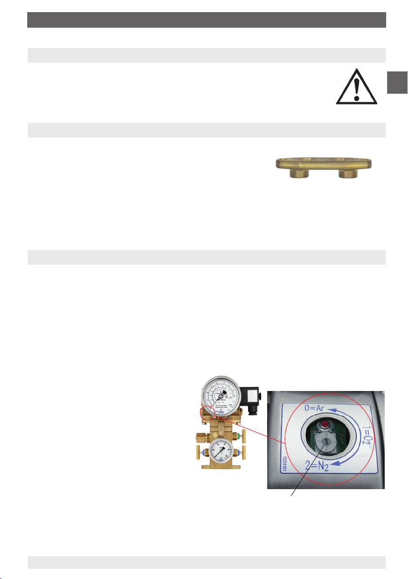
With multiple scales or interchangeable
dials (optional) the output signal of
4 ... 20 mA corresponding to each,
can be stored in a microprocessor.
The output signal can be changed over
to the desired uid type by rotating the
optional BCD switch (accessible through
a cover cap on the left side of the case)
using a screwdriver.
Electrical zero point (with option BCD switch)
BCD switc h (scale select ion switch) and
zero poi nt button (cover ca p removed)
If a zero point compensation is required (e.g. after mechanical zero point correction), the
instrument must rst be de-energised (pull the plug). Afterwards re-establish the power supply
(insert the plug) and press the zero point button for approx. 1 sec. within 30 sec.
11592011.04 06/2014 GB/D/F/I
WIKA operating instructions dierential pressure gauge models 712.15.100, 732.15.100
9
Page 10
8. Transmitter for level measurement
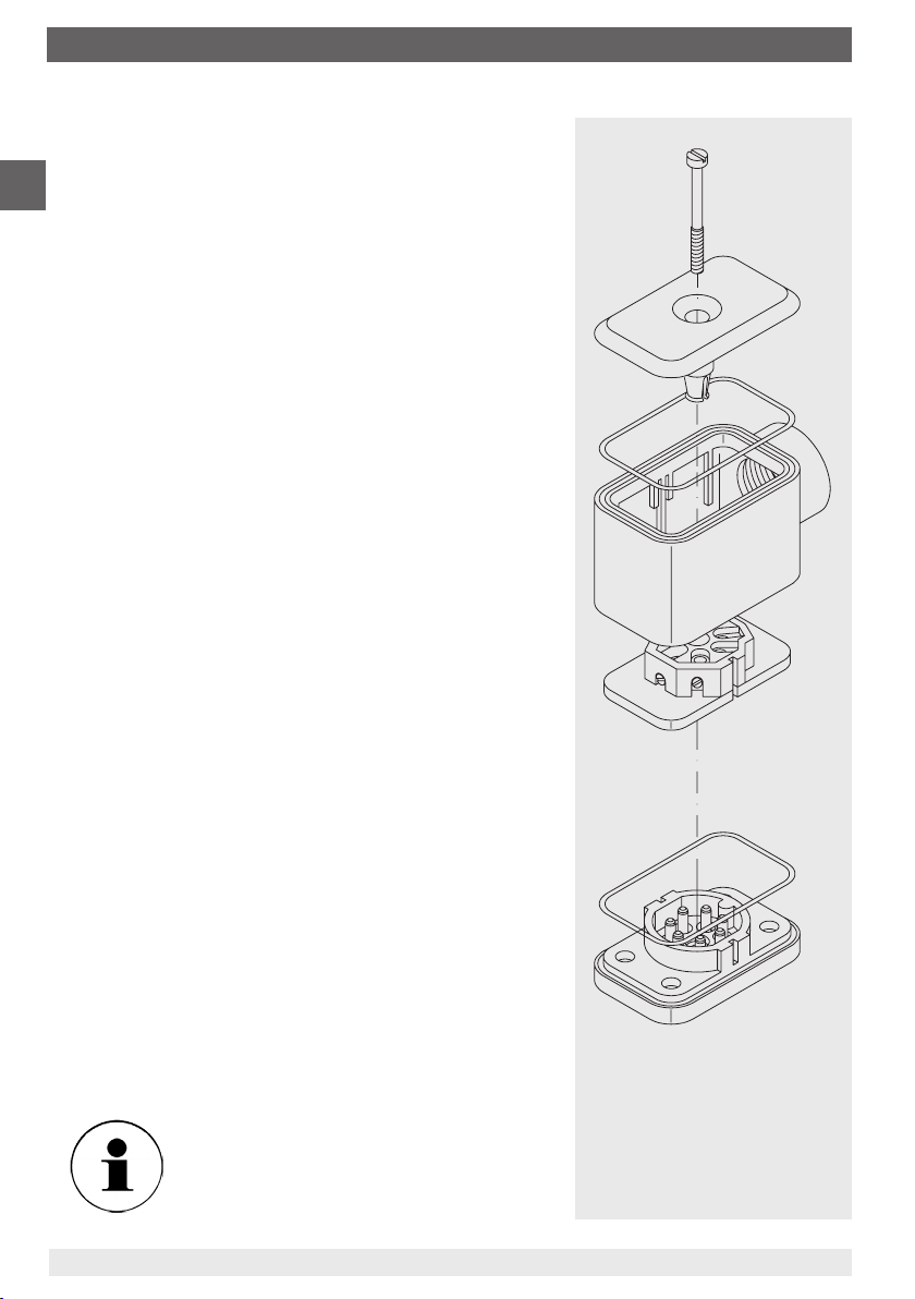
Electrical zero point (without option BCD switch)
If the mechanical zero point is changed by means of the
GB
adjustable pointer, the electrical zero point must be reset to
the mechanical zero point.
First depressurise the pressure gauge.
Loosen the complete cable hood on the right-hand side of
the pressure gauge by completely unscrewing the screw
on the top of the cable hood cover
screwdriver (0.6 x 3.5 mm).
using an appropriate
Extract the screw. Remove the cable hood
socket insert
separate the pressure gauge from the power supply.
Remove the cable hood cover
and push the socket insert
entire cable hood
Use a short stranded wire with bare points at both ends
(max. permissible resistance 30 Ω) to bridge contacts 5 and
6 on the socket insert.
Reassemble the plug in reverse order. Place the plug, with
the attached piece of stranded wire, onto the pin insert
and thus reestablish the power supply.
Within a max. 30 seconds the new zero point will be stored
within the electronics. During this period, the current in the
loop will increase to 9.5 mA.
The new zero point also remains stored in the case of a
power failure.
Loosen the plug again in the same sequence as described above and remove the piece of stranded wire. After
reassembling the plug, the electrical output signal will once
more correspond to the indication of the mechanical pointer.
Ensure the seals
securely reinstalled to maintain the
protection class.
from the cable socket base and thus
from the cable hood
out downwards through the
.
with the
,
are properly and
Screw
Cable hood cover
Cable hood
Socket insert
Cable socket base
Seals
10
WIKA operating instructions dierential pressure gauge models 712.15.100, 732.15.100
11592011.04 06/2014 GB/D/F/I
Page 11
8. Transmitter for level measurement
Specications Models 891.44 and 892.44 (Ex Version)
Power supply UB
for Non-Ex version DC 12 V < UB ≤ 30 V
for Ex version see the section ‚Ex protection‘!
Permissible residual ripple
% of span/10 V
Supply voltage eect % ss ≤ 10
Output signal 4 … 20 mA, 2-wire system
Permissible max. load R
A for Non-Ex versions, Model 891.44:
Eect of load % of span ≤ 0.1
Output signal adjustment
Zero point, electrical A
djustment of zero point through brief bridging of terminals 5 and 6,
or using the „scale selection switch“ option, selectable via button
Scale selection 4 scales selectable via BCD switch
Linearity % of span ≤ 1.0 (limit point calibration)
Permissible
ambient temperatures °C -40 … +80, -40 … +60 with oxygen
Compensated temp. range °C -40 … +80
Temperature coecients in
compensated temp. range
Mean TK of zero
Mean TK of span
% of span/10 K
% of span/10 K
Ex protection according to EC-Type Examination Certicate
Ex certication EEx II 2G EEx ia IIC T6
Conformity specications
Power supply U
Short circuit rating I
Rating P
Internal capacitance C
Internal inductance L
i DC 14 … 30 V
i mA max. 100
i W max. 1
i nF 12
i mH negligible
Medium temperature °C -40 … +80, -40 … +60 with oxygen
Ambient temperature °C -40 … +60 (T6)
CE-Conformity interference emission and immunity per EN 61326
Wiring L-connector (screw terminals up to 2.5 mm²)
Wiring protection protected against reverse polarity and overvoltage
Ingress protection IP 65 per EN 60529 / IEC 529
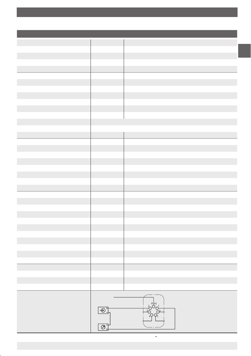
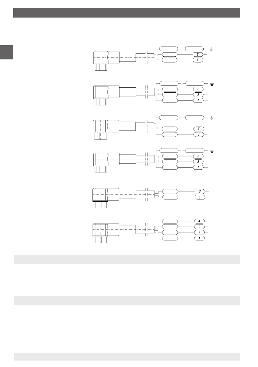
Wiring details,
2-wire
1) Only possible within 30 seconds of connecting the supply voltage
11592011.04 06/2014 GB/D/F/I
WIKA operating instructions dierential pressure gauge models 712.15.100, 732.15.100
≤ 0.1
A ≤ (UB - 12 V) / 0.02 A with RA in Ω and UB in Volt
R
for Ex versions, Model 892.44:
A ≤ (UB - 14 V) / 0.02 A with RA in Ω and UB in Volt
R
≤ 0.3
≤ 0.3
BSV 08 ATEX E 018 X for Model 892.44
Earth, connected
to case 2)
B+/Sig+
U
0V/Si g-
Terminals 3 , 4, 5 and 6: only for inte rnal
application
2) This connection must not be used
for equipotential bonding. The
instrument must be incorporated in
the equipotential bonding via the
process connection.
GB
1)
11
Page 12
8. Transmitter for level measurement
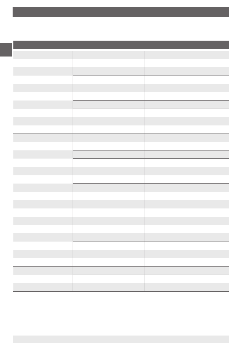
Trouble shooting
Defect Possible reason Remedy
GB
No signal output
Steady signal Pressure entry blocked Check tailpipes and pressure entry
despite pressure bore, if necessary clean it carefully
variation Open press. compensation valve Close pressure compensation valve
Steady and too high Electronic defect through Return pressure gauge to
signal despite of incorrect supply voltage manufacturer for repair
pressure variation or stray voltage spikes
Full span reading too low Supply voltage too low Adjust supply voltage
Zero signal too low Wrong zero compensation Readjust zero point
Zero signal too high Wrong zero compensation Readjust zero point
Failure of power supply Check power supply and wiring
Wiring interrupted (or broken) replace defective components
Transmitter incorrectly wired Check wiring;
if necessary rectify it
No pressure Check tailpipes
Open press. compensation valve
Electronic defect e.g. through Return pressure gauge to
incorrect supply voltage manufacturer for repair
or stray voltage spikes
Electronic defect e.g. through Return pressure gauge to
incorrect supply voltage manufacturer for repair
or stray voltage spikes
Transmitter defect after being Return pressure gauge to
over-pressured manufacturer for repair
Load impedance too high Consider permissible max. load
Wrong scale selected Check position of scale selection
Transmitter over-pressured Return pressure gauge to
Close pressure compensation valve
switch
manufacturer for repair
12
WIKA operating instructions dierential pressure gauge models 712.15.100, 732.15.100
11592011.04 06/2014 GB/D/F/I
Page 13
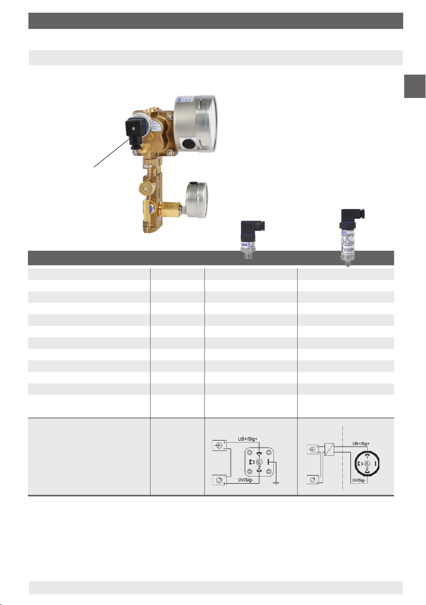
9. Transmitter for working pressure indication
9. Transmitter for working pressure indication (optional)
Standard version model A-10
or Ex version model IS-20
The transmitters for the working pressure
are screwed in sideways, on the left side of
the minus measurement chamber and can,
if necessary, be retrotted on-site.
Pressure connection for Transmitter:
G 1/4 (male)
Transmitter for working
pressure indication
Specications A-10 IS-20
Data sheet PE 81.60 PE 81.50
Design standard intrinsically safe
Pressure ranges bar 0 ... 6 to 0 ... 60 0 ... 6 to 0 ... 60
Outputs mA 4 ... 20 4 ... 20 (line transformer)
Medium temperature °C -30 ... +100 -20 ... +80
Ambient temperature °C -30 ... +100 -20 ... +80
Wetted parts stainless steel stainless steel
Power supply U
Maximum load R
Accuracy
BFSL % of span ≤ 0.5 ≤ 0.25
Compensated temperature
range
Wiring details,
2-wire
B DC 8 V < UB ≤ 30 V 10 V < UB ≤ 30 V
A Ohm RA ≤ (UB - 8 V) / 0.02 A RA ≤ (UB - 10 V) / 0.02 A
°C 0 ... +80 °C 0 ... +80 °C
Non hazardous
area
Hazardous
(classied) area
GB
The corresponding operating instructions are included in the delivery
of each dierential pressure gauge with integrated transmitter for
working pressure indication.
11592011.04 06/2014 GB/D/F/I
WIKA operating instructions dierential pressure gauge models 712.15.100, 732.15.100
13
Page 14
10. Switch contacts
10. Switch contacts (optional)
These switch contacts are tted into the case of a pressure gauge and intended to make or
GB
break an electric control circuit triggered by the position of the instrument‘s pointer.
Versions
Single and double magnetic snap-action contacts or single and double inductive alarm
sensors. Please refer to data sheet AC 08.01 for technical data.
The modular switch contact is a self-contained unit, which can be built onto the pressure
gauge within a few minutes.
The switch contacts provide IP65 ingress protection even for oil-lled gauges. The connection to the instrument pointer is made by means of a special fork so that a carrying pin at
the pointer itself is not necessary. By means of this simple mounting, the instrument can be
converted into a contact measuring instrument quickly and inexpensively.
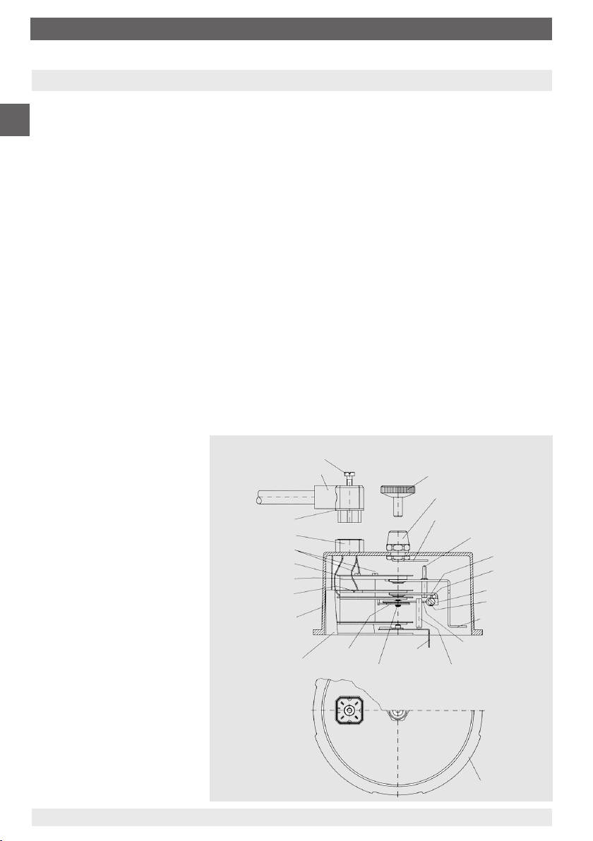
The switch contacts mainly comprise:
the pre-wired switch contact, which is provided with a special foot and a fork coupling
a transparent hood (polycarbonate) with dovetail lead into which the alarm contact is
pushed and which is fastened by means of a recessed head screw
a 4-pin plug socket, injection-moulded or welded to the transparent cover
an adjustable lock, mounted in the middle of the transparent cover.
The set pointers of the built-in
switch contact are adjusted, to
the value at which the contact
should switch, from the outside
via the adjustable lock using a
separate or a rigidly mounted
key.
The switch contacts are
designed to allow the instrument pointer to move beyond
the adjusted set pointer after
contact actuation takes place,
with the contact remaining
actuated.
The design therefore guarantees a stable switching condition, which corresponds to
the position of the instrument
pointer, even if the power fails.
14
WIKA operating instructions dierential pressure gauge models 712.15.100, 732.15.100
Plug with cable
Plug seal
Plug socket
Type plate screws
Type plate
Front plate
Connection
Transparent hood
Special foot
with dovetail lead
Plug screw
Spiral spring
Coupling fork
Ruby bearing
Spanner
Adjustable lock
Metal ag
Adjustable pin
Carrying arm
Contact pin
Magnet carrying
plate
Screw-in magnet
Desired value
indicator, red
Contact arm with
plate spring
Carrying pin of coupling fork
Bayonet rim
11592011.04 06/2014 GB/D/F/I
Page 15

10. Switch contacts
Mounting of switch contacts
Legend
Self-contained unit with switch
contact for level measurement
Connector plug
First the snap t style bezel with sealing ring, and the gauge window, must be removed. Prior
to attaching the transparent hood to the measuring instrument, the contacts must be adjusted
in accordance with their operating range.
Using the magnetic snap-action contact, the magnetic retention force must be adapted to the
instrument-specic conditions by adjusting (twisting) the screw-in magnet. The magnet must
then be protected against unintentional adjustment by using an appropriate locking varnish.
The small plate spring at the exible contact arm must be angled accordingly.
The fully-adjusted unit must now be tted to the gauge, together with the snap-t bezel, and
aligned to the extent that the fork coupling guiding the exible contact arms grips over the
gauge pointer without touching the dial. Should this occur, the carrying fork must be shortened using a suitable cutting tool.
The contacts are best adjusted when they are factory-tted.
By snapping the bezel onto the case, the whole contact unit will be xed to the pressure
gauge.
Connector plug
As counterpart to the connector base welded
onto the transparent hood
Material: PA 6 - GF 30
Colour: grey
Connection: stripped and tinned wires
Ingress protection: IP 65 per EN 60529 / IEC 529
For magnetic snap-action contacts:
Connector plug 3 poles + l (250 V max.)
with 2 m cable 4 x 1.0 mm
2
For inductive alarm sensors:
Low voltage execution without protective earth conductor
Connector plug 4 poles (50 V max.)
with 2 m cable 4 x 0.75 mm
2
Extent of delivery: 1 plug with cable,
1 central screw M3 x 20 and 1 gasket
11592011.04 06/2014 GB/D/F/I
WIKA operating instructions dierential pressure gauge models 712.15.100, 732.15.100
Gasket
GB
15
Page 16
10. Switch contacts ... 12. Disposal
Terminal conguration
Magnetic snap-action
GB
contacts:
Single contact,
NS 100
Double contact,
NS 100
Single contact,
NS 160
Double contact,
NS 160
Inductive alarm sensors:
Single contact,
NS 100 and 160
Double contact,
NS 100 and 160
green/yellow
blue
brown
green/yellow
blue
brown
black
green/yellow
brown
black
green/yellow
blue
brown
black
yellow
white
violet
yellow
black
white
green/yellow
1st c ontac t
common
green/yellow
1st c ontac t
common
2nd contact
green/yellow
common
2nd contact
green/yellow
1st c ontac t
common
2nd contact
1st contac t +
1st contac t -
1st contac t +
1st contac t 2nd cont act 2nd cont act +
11. Maintenance
WIKA dierential pressure gauges require no maintenance or servicing and will give very long
service when handled and operated properly.
12. Disposal
Incorrect disposal can put the environment at risk.
Dispose of instrument components and packaging materials in an environmentally compatible
way and in accordance with the country-specic waste disposal regulations.
16
WIKA operating instructions dierential pressure gauge models 712.15.100, 732.15.100
11592011.04 06/2014 GB/D/F/I
Page 17
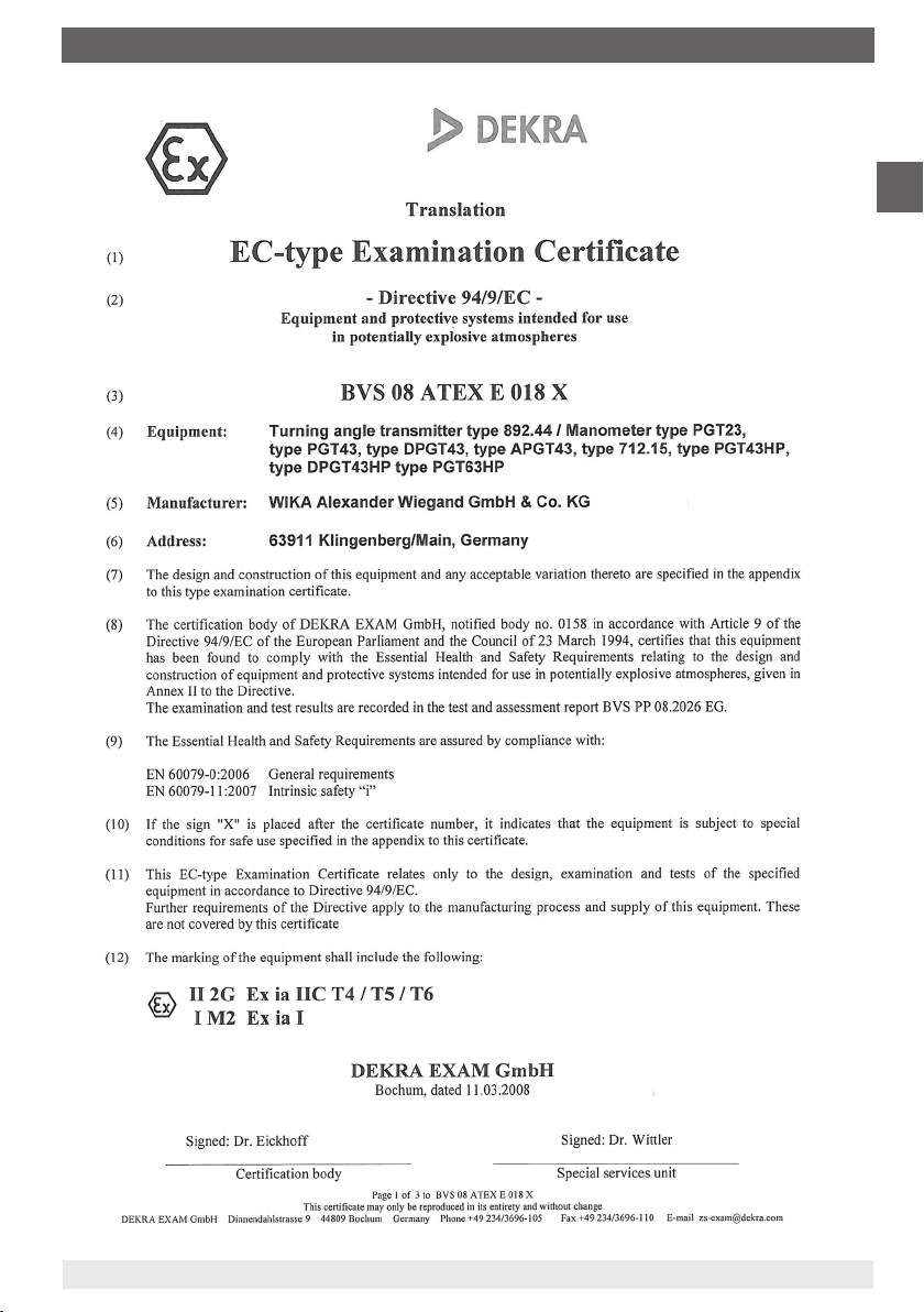
Enclosure 1
GB
11592011.04 06/2014 GB/D/F/I
WIKA operating instructions dierential pressure gauge models 712.15.100, 732.15.100
17
Page 18
Enclosure 1
GB
18
WIKA operating instructions dierential pressure gauge models 712.15.100, 732.15.100
11592011.04 06/2014 GB/D/F/I
Page 19
Enclosure 1
GB
11592011.04 06/2014 GB/D/F/I
WIKA operating instructions dierential pressure gauge models 712.15.100, 732.15.100
19
Page 20

GB
20
WIKA operating instructions dierential pressure gauge models 712.15.100, 732.15.100
11592011.04 06/2014 GB/D/F/I
Page 21
Inhalt
Inhalt
1. Sicherheit 22
2. Allgemeines 22
3. Montage 22
4. Dierenzdruckanzeige 24
5. Ventilblock mit Betriebsdruckanzeige (Option) 26
6. Applikationshinweis 27
7. Adapter für Prozessanschluss (Option) 27
8. Transmitter für Füllstandanzeige (Option) 27
9. Transmitter für Betriebsdruckanzeige (Option) 31
10. Schaltkontakte (Option) 32
11. Wartung 34
12. Entsorgung 34
Anlage 1: EG-Baumusterprüfbescheinigung
(Ex-Zulassung) für Drehwinkelgeber Typ 892.44 35
D
Information
Dieses Zeichen gibt Ihnen Informationen, Hinweise
oder Tipps.
Warnung!
Dieses Symbol warnt Sie vor Handlungen, die Schäden
an Personen oder am Gerät verursachen können.
11592011.04 06/2014 GB/D/F/I
WIKA Betriebsanleitung Dierenzdruckmessgerät Typen 712.15.100, 732.15.100
21
Page 22

1. Sicherheit ... 3. Montage
1. Sicherheit
WARNUNG!
Vor Montage, Inbetriebnahme und Betrieb sicherstellen, dass das richtige
Dierenzdruckmessgerät hinsichtlich Messbereich, Ausführung und spezi-
D
2. Allgemeines
Vorliegende Betriebsanleitung baut auf folgende Informationen auf:
EN 837-2: Auswahl- und Einbauempfehlungen für Druckmessgeräte
Datenblatt PM 07.29: Dierenzdruckmessgeräte Typen 712.15.100, 732.15.100
Datenblatt PM 02.01, PM 02.02: Druckmessgeräte mit Rohrfeder
schen Messbedingungen ausgewählt wurde.
Alle Arbeiten dürfen nur im spannungslosen Zustand erfolgen.
Bei Nichtbeachten können schwere Körperverletzungen und/oder
Sachschäden auftreten.
Nur entsprechend qualiziertes Fachersonal darf an diesen Geräten
arbeiten.
3. Montage
Die Montage des Dierenzdruckmessgerätes erfolgt in Anlehnung an die Einbau-
empfehlungen für Druckmessgeräte nach EN 837-2 /7.
Messleitungen vor der Gerätemontage gründlich durch Abklopfen und Ausblasen
oder Durchspülen reinigen
Messgeräte sollen erschütterungsfrei montiert und betrieben werden
Befestigung über: - starre Messleitungen und/oder
- 4 Montagebohrungen M8 im Messansch
Messgeräte sollen vor Verschmutzung und starken Temperaturschwankungen
geschützt sein
Maximal zulässige Messsto-/Umgebungstemperatur darf nicht überschritten werden
Montage des Druckanschlusses nach angebrachten Symbolen j und
j
hoher Druck ⇒ Bodendruck (p
i
niedriger Druck ⇒ Betriebsdruck/Überlagerungsdruck (p
p
= pFL + pD
B
(wobei p
22
= hydrostatischer Druck der Flüssigkeit = r • g • h)
FL
WIKA Betriebsanleitung Dierenzdruckmessgerät Typen 712.15.100, 732.15.100
)
B
)
D
i
11592011.04 06/2014 GB/D/F/I
Page 23

3. Montage
Montagearten zur Füllstandsmessung
Standard bei Tiefkälteanlagen 2 Beispiele mit Kondensatanfall
(verüssigte Gase)
Kondensat
⇔
Niveau-
p
D
p
D
gefäß
ZufuhrZufuhrZufuhr
D
p
D
Δp Δp Δp
p
D
p
B
p
D
Entnahme Entnahme
p
B
i ji j
i j
hhh
Entnahme
Kondensat
Montage an Wand
Anbringung/Befestigung an den 4 Montagebohrungen M8 / 2 Befestigungsbohrungen Ø 8,5
Druckanschlüsse
Montagebohrungen M8
Druckausgleichsventil
Absperrventil
j
Befestigungs-
bohrun gen Ø 8,5
ruckanschlüsse
D
G 1/4
G 1/4
Prüf
schluss
Absperrventil
i
11592649.01
an-
11592011.04 06/2014 GB/D/F/I
WIKA Betriebsanleitung Dierenzdruckmessgerät Typen 712.15.100, 732.15.100
23
Page 24

3. Montage / 4. Dierenzdruckanzeige
Option
Schalttafeleinbau
Schalttafelausschnitt
D
Schalttafel
4. Dierenzdruckanzeige
Die Messspanne des Dierenzdruckmessgerätes kann je nach Messzelle auf die in der
Tabelle angegebenen Messbereichsgrenzen eingestellt werden. Die Einstellung sollte
zweckmäßig auf dem Prüfstand erfolgen, kann jedoch auch direkt an der Messstelle mittels
Handprüfpumpe vorgenommen werden.
11563843.01
Messbereichsgrenzen
Messzelle Einstellbare Messbereiche
von bis
60 mbar 0 ... 40 mbar - 0 ... 60 mbar
90 mbar 0 ... 60 mbar - 0 ... 90 mbar
120 mbar 0 ... 80 mbar - 0 ... 120 mbar
165 mbar 0 ... 110 mbar - 0 ... 165 mbar
240 mbar 0 ... 160 mbar - 0 ... 240 mbar
330 mbar 0 ... 220 mbar - 0 ... 330 mbar
480 mbar 0 ... 320 mbar - 0 ... 480 mbar
660 mbar 0 ... 440 mbar - 0 ... 660 mbar
975 mbar 0 ... 650 mbar - 0 ... 975 mbar
1.350 mbar 0 ... 900 mbar - 0 ... 1.350 mbar
1.725 mbar 0 ... 1.150 mbar - 0 ... 1.725 mbar
24
WIKA Betriebsanleitung Dierenzdruckmessgerät Typen 712.15.100, 732.15.100
11592011.04 06/2014 GB/D/F/I
Page 25

4. Dierenzdruckanzeige
Spanneverstellung
D
Spanneverstellung
Inbus-Schraubendreher
(im Lieferumfang enthalten)
Rechtsdrehen: kleinerer Messbereich
Linksdrehen: größerer Messbereich
Verschlusskappe zur
Spanneverstellung
1. Die Spanneverstellung ist am Gehäuseumfang bei 4 Uhr durch Abnehmen der Verschlusskappe zugänglich.
2. Das Gerät mit dem gewünschten Nenndruck beaufschlagen.
3. Mittels Inbus-Schraubendreher (SW 3 mm) in die Trichterführung eintauchen und durch
Rechts- (kleinerer Messbereich) oder Linksdrehen (größerer Messbereich) den Zeiger auf
Endwert verstellen. Danach ist das Messgerät bereits auf den gewünschten Messbereich
eingestellt.
4. Ist das Messgerät mit einem Ferngeber Typ 89x.44 ausgerüstet (siehe Seite 27), so ist mit
dieser Prozedur auch das Ausgangssignal auf den neuen Messbereich eingestellt.
5. Nach Beendigung der Einstellung ist das Gerät wieder mit der Verschlusskappe zu
verschließen.
Zusätzliche Druckanschlüsse
Druckanschlüsse
G 1/4
Drei zusätzliche G ¼ Innengewinde
an Minusmessstokammer (rechter
Messzellenansch bei Ansicht des
Gerätes von hinten) z. B. zum Anschluss
eines Druckschalters, Sicherheitsventiles
oder Messumformers Typ A-10 Cryo bzw.
IS-20
Zwei G ¼ Innengewinde an
Plusmessstokammer (linker
Messzellenansch bei Ansicht
Montagebohrungen M8
des Gerätes von hinten) z. B. zur
Rekalibrierung
11592011.04 06/2014 GB/D/F/I
WIKA Betriebsanleitung Dierenzdruckmessgerät Typen 712.15.100, 732.15.100
Druckanschlüsse G 1/4
11557711.01AB
25
Page 26

5. Ventilblock mit Betriebsdruckanzeige (Option)
5. Ventilblock mit Betriebsdruckanzeige (Option)
Der optional ananschbare kompakte Ventilblock mit Betriebsdruck-Messgerät NG 63
ermöglicht die zentrale Messung von Füllstand und Betriebsdruck in einem Gerät.
Absperrung der Messleitungsdrücke ohne
Störung des Betriebsablaufes
D
BetriebsdruckMessgerät
NG 63
Prüf
anschluss
M20 x 1,5
Absperrventil
i
Druckausgleichsventil
Absperrventil
j
c) Über zusätzliches G ¼ Innengewinde in der Pluskammer des Messsystems wird
Drucknormal und Druckerzeuger angeschlossen
d) Im Ventilblock auf der Minusseite Prüfanschluss-Schraube entfernen
e) Plusseite kann jetzt mit Druck beaufschlagt werden
f) Nach erfolgter Justage:
- Prüfanschlussschraube wieder schließen
- Drucknormal und Druckerzeuger wieder entfernen und Anschluss verschließen
- zuerst Plus-, dann Minusabsperrhahn langsam önen
Prüfanschluss M20 x 1,5 für die Überprüfung des Betriebsdruck-Messgerätes
Mit dem Druckausgleichsventil wird eine Nullpunktkontrolle im laufenden Betriebsprozess
(bei geönetem Ventil) ermöglicht.
a) Plus- und Minusabsperrhahn schließen
b) Danach Druckausgleichsventil önen
Der Messsto strömt von der Seite höheren Druckes nach der Gegenseite, Dierenzdruck
am Messgerät fällt auf Null (Dierenzdruckanzeige muss auf Null, d.h. in den Bereich des
Nullpunkt-Toleranzbandes gehen, Gerätefunktion ist damit in Ordnung).
Bei Abweichung kann eine Nullpunktkorrektur über den
standardmäßig eingebauten Verstellzeiger erfolgen (vorher die
Spannbügel lösen und Sichtscheibe und Dichtung entfernen).
Die Nullpunkt-Verstellung wird durch Verdrehen der Schlitzschraube am Verstellzeiger erreicht. Nach erfolgter Nullpunktkorrektur Schnappring incl. Sichtscheibe und Dichtung
wieder befestigen und Druckausgleichsventil schließen.
Anschließend ist bei Ausführungen mit integriertem Transmitter
auch dessen Nullpunkt zu kontrollieren (siehe Seite 27).
c) Druckausgleichsventil wieder verschließen
d) zuerst Plus-, dann Minusabsperrhahn langsam önen
26
WIKA Betriebsanleitung Dierenzdruckmessgerät Typen 712.15.100, 732.15.100
- zur Gerätedemontage/-prüfung
- zum Schutz des Gerätes gegen unzulässige Überdruckbelastung bei n-facher
Prüfdruckbelastung von Anlagen
11592649.01AB
Schutz des Gerätes gegen Druckstöße/
-schläge und damit undenierten
Betriebsverhältnissen
Gerätestilllegung, wenn über längere Be-
triebszeiten keine Messung erforderlich,
d.h. nur sporadische Messungen (zur
Erhöhung der Lebensdauer von Dierenz-
und Betriebsdruck-Messgeräten mit hoher
Frequenz der Druckwechsel)
Rekalibrierung des Dierenzdruckmess-
gerätes (Tankinhaltsanzeige)
a) Plus- und Minusabsperrhahn schließen
b) Danach Druckausgleichsventil önen,
kurz abwarten und anschließend Druckausgleichsventil wieder verschließen
Schlitzschraube
11592011.04 06/2014 GB/D/F/I
Page 27

6. Applikationshinweis ... 8. Transmitter für Füllstandanzeige
6. Applikationshinweis
Bei gefährlichen Messstoen, wie z. B. Sauersto, Acetylen, brennbaren
oder giftigen Stoen, sowie bei Druckbehältern etc., sind über die allgemei-
nen Regeln hinaus die bestehenden Vorschriften/Richtlinien zu beachten.
7. Adapter für Prozessanschluss (Option)
Die Adapter können entweder direkt an das Dierenzdruckmessgerät oder an den Ventilblock angeanscht werden.
4 verschiedene Prozessanschlüsse stehen zur Auswahl:
2 x G 1/4, Innengewinde, Achsabstand 31 mm oder 54 mm
2 x 1/4 NPT, Innengewinde, Achsabstand 31 mm oder 54 mm
Bei Einzelbestellung sind alle für die Montage am Dierenzdruckmessgerät oder am Ventilblock erforderlichen Teile im Lieferumfang enthalten:
2 x Sechskantschrauben M8 x 16, 2 x Sechskantschrauben M8 x 28, 2 x Mutter M8 und
2 x O-Ring Dichtung
8. Transmitter für Füllstandanzeige (Option)
Standardausführung Typ 891.44
Ex-Ausführung Typ 892.44
WIKA Dierenzdruckmessgeräte mit integriertem Transmitter Typ 89x.44 verbinden alle
Vorteile einer mechanischen Anzeige vor Ort mit den Forderungen nach einer elektrischen
Signalübertragung für eine moderne Messwerterfassung in der Industrie.
Der Transmitter ist im Gehäuse der Füllstandanzeige integriert. Die Messspanne (elektri-
sches Ausgangssignal) wird automatisch mit der mechanischen Anzeige eingestellt, d.h. die
Skale über 270 Winkelgrade entspricht 4 … 20 mA (siehe Punkt 4. Dierenzdruckanzeige).
Bei Mehrfachskalen oder wechselbaren
Steckskalen (Option) kann das darauf
abgestimmte Ausgangssignal von
4 ... 20 mA in einem Mikroprozessor
abgelegt werden.
D
Durch Verdrehen des optionalen BCDSchalters (erreichbar durch Abnehmen
einer Verschlusskappe links seitlich am
Gehäuse) mittels Schraubendreher lässt sich das Ausgangssignal auf die gewünschte Gasart umstellen.
BCD-Schalter (Skalenauswahlschalter) und
Elektrischer Nullpunkt (mit Option BCD-Schalter)
Nullpunkt-Taster (Verschlusskappe entfernt)
Sollte ein Nullpunktabgleich notwendig werden (z. B. nach erfolgter mechanischer
Nullpunktkorrektur), so ist das Gerät zunächst spannungsfrei zu schalten (Stecker abziehen).
Danach ist die Spannungsversorgung wieder herzustellen (Stecker montieren) und innerhalb
von 30 Sek. der Nullpunkt-Taster für ca. 1 Sek. zu drücken.
11592011.04 06/2014 GB/D/F/I
WIKA Betriebsanleitung Dierenzdruckmessgerät Typen 712.15.100, 732.15.100
27
Page 28

8. Transmitter für Füllstandanzeige
Elektrischer Nullpunkt (ohne Option BCD-Schalter)
Wird der mechanische Nullpunkt über den Verstellzeiger
verändert, sollte der elektrische Nullpunkt wieder dem
mechanischen angepasst werden.
Bringen Sie hierzu das Manometer zuerst in den drucklosen
D
Zustand.
Lösen Sie die ganze Kabelhaube an der rechten Manometerseite, in dem Sie mit einem Schlitzschraubendre-
her (0,6 x 3,5 mm) die Schraube
Kabelhaubendeckels
die Schraube heraus. Ziehen Sie die Kabelhaube
Buchseneinsatz
trennen somit das Manometer von der Spannungsversorgung.
vollständig lösen. Nehmen Sie
vom Kabeldosenunterteil ab und
an der Oberseite des
samt
Entfernen Sie den Kabelhaubendeckel
haube
und drücken Sie den Buchseneinsatz ganz
durch die Kabelhaube
Überbrücken Sie die Kontakte 5 und 6 an dem Buchseneinsatz mit einem kurzen, an beiden Enden abisolierten Stück
Litze (max. zulässiger Widerstand 30 Ω).
Montieren Sie den Stecker wieder in umgekehrter Reihenfolge. Stecken Sie den Stecker mit montiertem Stück
Litzendraht auf den Stifteinsatz
Versorgungsspannung wieder her.
Innerhalb von max. 30 Sekunden wird der neue Nullpunkt in
der Elektronik gespeichert. Während dieser Zeit steigt der
Strom in der Schleife auf 9,5 mA.
Der neue Nullpunkt bleibt auch bei Spannungsausfall auf
Dauer gespeichert.
Lösen Sie wieder den Stecker in der oben beschriebenen
Reihenfolge und entfernen das Stück Litzendraht. Nach
erneutem Montieren des Steckers ist das elektrische
Ausgangssignal wieder deckungsgleich mit der Anzeige
des mechanischen Zeigers.
Damit die Schutzart erhalten bleibt,
unbedingt die Dichtungen
montieren.
nach unten heraus.
von der Kabel-
und stellen somit die
wieder
Schraube
Kabelhaubendeckel
Kabelhaube
Buchseneinsatz
Kabeldosenunterteil
Dichtungen
28
WIKA Betriebsanleitung Dierenzdruckmessgerät Typen 712.15.100, 732.15.100
11592011.04 06/2014 GB/D/F/I
Page 29

8. Transmitter für Füllstandanzeige
Technische Daten Typen 891.44 und 892.44 (Ex-Ausführung)
Hilfsenergie UB
für Nicht-Ex-Ausführungen DC 12 V < UB ≤ 30 V
für Ex-Ausführungen siehe im Abschnitt Ex-Schutz!
Einuss der Hilfsenergie % v. EW/10 V ≤ 0,1
Zulässige Restwelligkeit % ss ≤ 10
Ausgangssignal 4 … 20 mA, Zweileiter
Zulässige max. Bürde R
Bürdeneinuss % vom EW ≤ 0,1
Einstellbarkeit
Nullpunkt, elektrisch Nullung durch kurzzeitiges Überbrücken der Klemmen 5 und 6
Skalenauswahl 4 Skalen über BCD-Schalter einstellbar
Kennlinienabweichung % d. Spanne ≤ 1,0 (Grenzpunkteinstellung)
Zulässige
Umgebungstemperaturen °C -40 … +80, -40 … +60 bei Sauersto
Kompensierter Temp.-bereich °C -40 … +80
Temperaturkoezienten im
kompensierten Temp.-bereich
Mittlerer TK Nullpunkt
Mittlerer TK Spanne
Ex-Schutz nach EG-Baumusterprüfbescheinigung
Zündschutzart EEx II 2G EEx ia IIC T6
Sicherheitstechn. Höchstwerte
Hilfsenergie U
i DC 14 … 30 V
Kurzschlussstrom I
Leistung P
i W max. 1
innere Kapazität C
innere Induktivität L
Messstotemperatur °C -40 … +80, -40 … +60 bei Sauersto
Umgebungstemperatur °C -40 … +60 (T6)
CE-Kennzeichen Störemission und Störfestigkeit nach EN 61326
Elektrischer Anschluss Winkelsteckverbinder
Elektrische Schutzarten Verpolungs- und Überspannungsschutz
Schutzart IP 65 nach EN 60529 / IEC 529
Belegung der Anschlussklemmen, 2-Leiter
1) Nur innerhalb von 30 Sekunden nach Anlegen der Versorgungsspannung möglich
11592011.04 06/2014 GB/D/F/I
WIKA Betriebsanleitung Dierenzdruckmessgerät Typen 712.15.100, 732.15.100
A für Nicht-Ex-Ausführungen, Typ 891.44:
A ≤ (UB - 12 V) / 0,02 A mit RA in Ω und UB in Volt
R
für Ex-Ausführungen, Typ 892.44:
A ≤ (UB - 14 V) / 0,02 A mit RA in Ω und UB in Volt
R
oder bei Option „Skalenauswahlschalter“ einstellbar über Taster
% d. Spanne/10 K
% d. Spanne/10 K
≤ 0,3
≤ 0,3
BSV 08 ATEX E 018 X für Typ 892.44
i mA max. 100
i nF 12
i mH vernachlässigbar
(Schraubklemmen bis 2,5 mm²)
Erde, verbunden
mit Gehäuse 2)
B+/Sig+
U
0V/Si g-
Klemme n 3, 4, 5 und 6: nur für inte rnen
Verbrauch
2) Dieser Anschluss darf nicht für
den Potentialausgleich verwendet
werden. Das Gerät muss über
den Prozessanschluss in den
Potentialausgleich einbezogen
werden.
D
1)
29
Page 30

8. Transmitter für Füllstandanzeige
Maßnahmen bei Störungen
Störung Mögliche Ursache Maßnahme
Kein Ausgangssignal keine Versorgungsspannung Spannungsversorgung und Leitungen
Leitungsbruch überprüfen; ggf. defekte Teile
D
Ferngeber falsch Anschlüsse überprüfen;
angeschlossen Anschlüsse ggf. korrigieren
kein Eingangsdruck Druckzuführung überprüfen
Druckausgleichsventil oen Druckausgleichsventil schließen
Elektronik defekt z. B. durch zu Messgerät zur Instandsetzung
hohe Versorgungsspannung an Hersteller
oder durch Fremdspannung
Gleichbleibendes Eingangskanal verstopft Eingangskanal bzw. Drosselschraube
Ausgangssignal reinigen
bei Druckänderung Druckausgleichsventil oen Druckausgleichsventil schließen
Elektronik defekt z.B. durch zu Messgerät zur Instandsetzung
hohe Versorgungsspannung an Hersteller
oder durch Fremdspannung
Ferngeber defekt nach Messgerät zur Instandsetzung
mechanischer Überbelastung an Hersteller
Zu hohes, bei Druckän- Elektronik defekt durch zu Messgerät zur Instandsetzung
derung gleichbleibendes hohe Versorgungsspannung an Hersteller
Ausgangssignal oder durch Fremdspannung
Signalspanne zu klein Versorgungsspannung zu niedrig Versorgungsspannung korrigieren
Bürde zu hoch max. zulässige Bürde beachten
falsche Skala gewählt Stellung des Skalenauswahlschalters
Nullpunktsignal zu klein fehlerhafter Nullpunktabgleich Nullpunkt neu einstellen
Nullpunktsignal zu groß fehlerhafter Nullpunktabgleich Nullpunkt neu einstellen
mechanische Überlastung Ferngeber neu justieren, ggf. Mess-
austauschen
überprüfen
gerät zur Instandsetzung an Hersteller
30
WIKA Betriebsanleitung Dierenzdruckmessgerät Typen 712.15.100, 732.15.100
11592011.04 06/2014 GB/D/F/I
Page 31

9. Transmitter für Betriebsdruckanzeige
9. Transmitter für Betriebsdruckanzeige (Option)
Standardausführung Typ A-10
oder Ex-Ausführung Typ IS-20
Die Transmitter für den Betriebsdruck
werden links, seitlich in die Minus-
Messstokammer eingeschraubt und
können bei Bedarf auch vor Ort angebaut
werden.
Druckanschluss des Transmitters:
Transmitter für
Betriebsdruckanzeige
Technische Daten A-10 IS-20
Datenblatt PE 81.60 PE 81.50
Bauform standard eigensicher
Messbereiche bar 0 ... 6 bis 0 ... 60 0 ... 6 bis 0 ... 60
Ausgänge mA 4 ... 20 4 ... 20 (Speisetrenner)
Messstotemperatur °C -30 ... +100 -20 ... +80
Umgebungstemperatur °C -30 ... +100 -20 ... +80
Messstoberührte Teile CrNi-Stahl CrNi-Stahl
Hilfsenergie U
Zulässige max. Bürde R
Genauigkeit
Toleranzbandeinstellung, BFSL % d. Spanne ≤ 0,5 ≤ 0,25
Kompensierter Temperaturbereich
Belegung der Anschlussklemmen, 2-Leiter
B DC 8 V < UB ≤ 30 V 10 V < UB ≤ 30 V
A Ohm RA ≤ (UB - 8 V) / 0,02 A RA ≤ (UB - 10 V) / 0,02 A
°C 0 ... +80 °C 0 ... +80 °C
Außengewinde G 1/4
Nicht Ex-Bereich
Ex-Bereich
D
Bei jedem Dierenzdruckmessgerät mit angebautem Transmitter
für Betriebsdruckanzeige wird bei Auslieferung die entsprechende
Betriebsanleitung beigelegt.
11592011.04 06/2014 GB/D/F/I
WIKA Betriebsanleitung Dierenzdruckmessgerät Typen 712.15.100, 732.15.100
31
Page 32

10. Schaltkontakte
10. Schaltkontakte (Option)
Elektrische Schaltkontakte für Füllstandsanzeiger und/oder Betriebsdruck önen Stromkreise
in Abhänigigkeit von der Zeigerstellung der anzeigenden Messgeräte.
Ausführungen
1- und 2-fach Magnetspringkontakte oder 1- und 2-fach Induktiv-Kontakte
Technische Daten gemäß Datenblatt AC 08.01
D
Beim Schaltkontakt im Baukastensystem handelt es sich um eine Aufbaueinheit, die in
wenigen Minuten auf das Druckmessgerät aufgebaut werden kann.
Die Schaltkontakte sind in Schutzart IP 65 ausgeführt.
Die Ankopplung an den lstwertzeiger erfolgt über eine Spezialgabel, so dass am Zeiger selbst
kein Mitnehmerstift benötigt wird. Durch diese einfache Montage kann äußerst schnell und
preiswert in ein Kontakt-Messgerät umgebaut werden.
Die Schaltkontakte bestehen im wesentlichen aus:
dem bereits verdrahteten Schaltkontakt, der mit einem Spezialfuß und einer Gabel-
kupplung ausgerüstet ist,
einer Klarsichthaube (Material Polycarbonat) mit Schwalbenschwanzführung, in die der
Grenzsignalgeber mit dem Spezialfuß eingeschoben und mittels einer Kreuzschlitz-
schraube befestigt ist,
einem der Klarsichthaube angespritzten bzw. verschweißten Steckerunterteil (4-polig),
einem in der Mitte der Klarsichthaube montierten Verstellschloss.
Durch das Verstellschloss
mit separatem oder fest
montiertem Schlüssel werden
die Sollwertzeiger des eingebauten Schaltkontaktes von
außen auf den Wert eingestellt,
bei dem der Schaltvorgang
erfolgen soll.
Die Schaltkontakte sind so
konstruiert, dass der Istwertzeiger nach erfolgter Kontaktgabe über den eingestellten
Sollwertzeiger hinaus weiterlaufen kann; die einmal erfolgte
Kontaktgabe bleibt jedoch
erhalten.
Die Konstruktion garantiert
daher auch bei Stromausfall
einen stabilen, der Stellung des
Istwertzeigers entsprechenden
Schaltzustand.
32
WIKA Betriebsanleitung Dierenzdruckmessgerät Typen 712.15.100, 732.15.100
Anschlussstecker
mit Kabel
Steckerdichtung
Steckerunterteil
Typenschildschrauben
Typenschild
Frontplatte
Anschluss
Klarsichthaube
Spezialfuß mit
Schwalbenschwanzführung
Steckerschraube
Spiralfeder
Kupplungsgabel
Rubin-Lagersteine
Verstellschlüssel
Verstellschloss
Schlossfahne
Verstellstift
Trägerarm
Kontaktstift
Magnethalteblech
Einschraubmagnet
roter Sollwertzeiger
Kontaktarm mit
Blattfeder
Mitnehmerstift der Kupplungsgabel
Bajonettrand
11592011.04 06/2014 GB/D/F/I
Page 33

10. Schaltkontakte
Montage der Schaltkontakte
Legende
Aufbaueinheit mit Schaltkontakt für
Füllstandsanzeige
Anschlussstecker
Zuerst ist der Schnappring mit Dichtung und Sichtscheibe des Messgerätes zu entfernen.
Vor dem Aufsetzen der Klarsichthaube auf das Messgerät sind die Kontakte entsprechend
dem Anwendungsbereich einzustellen.
Beim Magnetspringkontakt ist die magnetische Haltekraft durch Einstellen (Verdrehen) des
Einschraubmagneten den gerätespezischen Gegebenheiten anzupassen und anschließend
mit einem geeigneten Sicherungslack gegen unbeabsichtigtes Verstellen zu sichern.
Die kleine Blattfeder am beweglichen Kontaktarm ist entsprechend abzuwinkeln.
Die fertig justierte Einheit wird nun mit dem Schnappring so auf das Messgerät aufgesetzt
und ausgerichtet, dass die Gabelkupplung, die die beweglichen Kontaktarme führt,
über den Istwertzeiger des Messgerätes greift, ohne das darunterliegende Zierblatt
zu berühren. Sollte dieses doch der Fall sein, so ist die Mitnehmergabel mit einem entsprechenden Schneidwerkzeug nach Bedarf zu kürzen.
Bei werkseitigem Anbau sind die Kontakte optimal justiert.
Durch das Anschnappen des Ringes an das Gehäuse wird die gesamte Kontakteinheit mit
dem Messgerät befestigt.
Anschlussstecker
Als Gegenstück zu dem auf der Klarsichthaube
verschweißten Steckerunterteil
Material: Isolierteile PA 6 - GF 30
Gehäusefarbe: grau
Anschlussart: Leitungsenden abisoliert und verzinnt
Schutzart: IP 65 nach EN 60529 / IEC 529
Für Magnetspringkontakte:
Anschlussstecker 3-polig + l (bis 250 V)
mit 2 m Kabel 4 x 1,0 mm
2
Für Induktiv-Kontakte:
Niederspannungsausführung ohne Schutzleiter
Anschlussstecker 4-polig (bis 50 V)
mit 2 m Kabel 4 x 0.75 mm
2
Lieferumfang: 1 Anschlussstecker am Anschlusskabel
angespritzt, 1 Zentralschraube M3 x 20 und 1 Dichtung
11592011.04 06/2014 GB/D/F/I
WIKA Betriebsanleitung Dierenzdruckmessgerät Typen 712.15.100, 732.15.100
Dichtung
D
33
Page 34

10. Schaltkontakte ... 12. Entsorgung
Anschlussbelegung
Magnetspringkontakte:
Einfachkontakt,
NG 100
D
Zweifachkontakt,
NG 100
Einfachkontakt,
NG 160
Zweifachkontakt,
NG 160
Induktiv-Kontakte:
Einfachkontakt,
NG 100 und 160
Zweifachkontakt,
NG 100 und 160
grün/gelb
blau
braun
grün/gelb grün/gelb
blau
braun
schwarz
grün/gelb grün/gelb
braun
schwarz
grün/gelb grün/gelb
blau
braun
schwarz
gelb
weiß
violett
gelb
schwarz
weiß
grün/gelb
1. Kon tak t
Gemeinsamer
1. Kon tak t
Gemeinsamer
2. Kontakt
Gemeinsamer
2. Kontakt
1. Kon tak t
Gemeinsamer
2. Kontakt
1. Kontakt +
1. Kontakt -
1. Kontakt +
1. Kontakt -
2. Kontak t -
2. Kontak t +
11. Wartung
WIKA-Dierenzdruckmessgeräte sind wartungsfrei und zeichnen sich bei sachgemäßer
Behandlung/Bedienung durch hohe Lebensdauer aus.
12. Entsorgung
Durch falsche Entsorgung können Gefahren für die Umwelt entstehen.
Gerätekomponenten und Verpackungsmaterialien entsprechend den landesspezischen
Abfallbehandlungs- und Entsorgungsvorschriften umweltgerecht entsorgen.
34
WIKA Betriebsanleitung Dierenzdruckmessgerät Typen 712.15.100, 732.15.100
11592011.04 06/2014 GB/D/F/I
Page 35

Anlage 1
D
11592011.04 06/2014 GB/D/F/I
WIKA Betriebsanleitung Dierenzdruckmessgerät Typen 712.15.100, 732.15.100
35
Page 36

Anlage 1
D
36
WIKA Betriebsanleitung Dierenzdruckmessgerät Typen 712.15.100, 732.15.100
11592011.04 06/2014 GB/D/F/I
Page 37

Anlage 1
D
11592011.04 06/2014 GB/D/F/I
WIKA Betriebsanleitung Dierenzdruckmessgerät Typen 712.15.100, 732.15.100
37
Page 38

D
38
WIKA Betriebsanleitung Dierenzdruckmessgerät Typen 712.15.100, 732.15.100
11592011.04 06/2014 GB/D/F/I
Page 39

Sommaire
Sommaire
1. Sécurité 40
2. Généralités 40
3. Installation 40
4. Manomètre pour pression diérentielle 42
5. Manifold avec indication de la pression de travail (option) 44
6. Conseils d‘utilisation 45
7. Adaptateurs pour raccordement process (option) 45
8. Transmetteur pour indication du niveau (option) 45
9. Transmetteur pour indication de la pression de travail (option) 49
10. Commutateurs (option) 50
11. Entretien 52
12. Mise au rebut 52
Attestation d‘examen CE (homologation Ex) pour
capteur rotatif des types 892.44 anglais
allemand
Informations
Ce signe vous donne des informations, des remarques
ou des conseils.
17-19
35-37
F
Avertissement !
Ce symbole vous avertit d'actions qui sont susceptibles
d'entraîner des dommages physiques ou matériels.
11592011.04 06/2014 GB/D/F/I
WIKA mode d‘emploi manomètre pour pression diérentielle types 712.15.100, 732.15.100
39
Page 40

1. Sécurité ... 3. Installation
1. Sécurité
AVERTISSEMENT !
Avant le montage, la mise en service et le fonctionnement, s‘assurer que
l‘appareil a été choisi de façon adéquate, en ce qui concerne la plage de
mesure, la version et les conditions de mesure spéciques.
Toutes les interventions doivent être eectuées hors tension.
F
Un non respect de cette consigne peut entraîner des blessures corporelles
graves et/ou des dégâts matériels.
Seul le personnel habilité et qualié est autorisé à manipuler les
instruments
2. Généralités
Le présent mode d‘emploi repose sur les informations suivantes:
EN 837-2: Recommandations pour le choix et l‘installation de manomètres
Fiche technique PM 07.29: Manomètre pour pression diérentielle types 712.15.100,
732.15.100
Fiche technique PM 02.01, PM 02.02: Manomètre à tube manométrique
3. Installation
Le montage du manomètre pour pression diérentielle s‘eectue conformément aux recommandations de montage pour manomètres suivant EN 837-2/7.
Avant de monter l‘appareil, bien nettoyer les raccords de l‘appareil de mesure.
Lors du montage ou de l‘utilisation, éviter toute exposition des appareils aux
vibrations et chocs.
Fixation des appareils: - Conduites rigides et/ou
- 4 trous de montage M8 dans le corps de l‘appareil
Protéger les appareils de la saleté et des fortes variations de température
Les températures max. admissibles pour le uide et la température ambiante ne doivent
pas être dépassées.
Montage du raccord de pression conformément aux symboles apposés j et
j
haute pression ⇒ Pression de contact (p
i
basse pression ⇒ Pression de service / Pression de recouvrement (p
p
= pFL + pD
B
(p
= Pression hydrostatique du liquide = r • g • h)
FL
40
WIKA mode d'emploi manomètre pour pression diérentielle types 712.15.100, 732.15.100
),
B
i
)
D
11592011.04 06/2014 GB/D/F/I
Page 41

3. Installation
Types de montage pour mesure de niveau
Standard avec installations cryogéniques 2 exemples avec formation de condensat
(Gaz liquides)
Condensat
⇔
Bac à
p
D
p
D
niveau
p
D
ArrivéeArrivéeArrivée
F
Δp Δp Δp
p
D
p
B
p
D
Prise Prise
p
B
i ji j
Condensat
Montage mural
Pose/xation sur les 2 trous de montage M8 / 2 trous de montage Ø 8,5
Trous de monta ge M8
Vanne
d’équilibrage
de la pression
Vanne d’arrêt
j
Trous de
montage Ø 8 ,5
Raccords de pression G 1/4
i j
hhh
Prise
Raccords de
pression G 1/4
Raccord
test
Vanne
d’arrêt
i
11592649.01
11592011.04 06/2014 GB/D/F/I
WIKA mode d‘emploi manomètre pour pression diérentielle types 712.15.100, 732.15.100
41
Page 42

3. Installation / 4. Manomètre pour pression diérentielle
Option
Encastrement
Découpe du panneau
F
Panneau
4. Manomètre pour pression diérentielle
L‘étendue de mesure du manomètre pour pression diérentielle peut en fonction de la cellule
de mesure être réglée selon les limites indiquées dans le tableau suivant. Idéalement, le
réglage doit être eectué sur un banc de test mais il peut également être fait au point de
mesure à l‘aide d‘une pompe manuelle.
11563843.01
Limites de l‘étendue de mesure
Celulle de mesure Etendues de mesure possibles
de à
60 mbar 0 ... 40 mbar - 0 ... 60 mbar
90 mbar 0 ... 60 mbar - 0 ... 90 mbar
120 mbar 0 ... 80 mbar - 0 ... 120 mbar
165 mbar 0 ... 110 mbar - 0 ... 165 mbar
240 mbar 0 ... 160 mbar - 0 ... 240 mbar
330 mbar 0 ... 220 mbar - 0 ... 330 mbar
480 mbar 0 ... 320 mbar - 0 ... 480 mbar
660 mbar 0 ... 440 mbar - 0 ... 660 mbar
975 mbar 0 ... 650 mbar - 0 ... 975 mbar
1.350 mbar 0 ... 900 mbar - 0 ... 1.350 mbar
1.725 mbar 0 ... 1.150 mbar - 0 ... 1.725 mbar
42
WIKA mode d'emploi manomètre pour pression diérentielle types 712.15.100, 732.15.100
11592011.04 06/2014 GB/D/F/I
Page 43

4. Manomètre pour pression diérentielle
Réglage de l‘étendue
Réglage de l‘étendue
Six pans creux
(compris dans la livraison)
F
Vers la droite: étendue de mesure plus faible
Vers la gauche: étendue de mesure plus grande
Capuchon pour le
réglage de l‘étendue
1. Le réglage de l‘étendue est accessible sur le pourtour du boîtier (au niveau de 4 heures)
en enlevant le capuchon.
2. Régler la pression nominale souhaitée sur l‘appareil.
3. Introduire un tournevis pour vis à six pans creux (3 mm) dans l‘ouverture (entonnoir) et
régler l‘aiguille sur la valeur nale en tournant vers la droite (étendue de mesure plus
faible) ou vers la gauche (étendue de mesure plus grande). Après celà le manomètre est
alors déjà réglé sur l‘étendue de mesure souhaitée.
4. Si l‘appareil de mesure est équipé d‘un transmetteur de type 89x.44 (voir page 45), le
signal de sortie est réglé également sur la nouvelle étendue de mesure grâce à cette
procédure.
5. A la n du réglage, refermer l‘appareil avec le capuchon.
Raccords de pression supplémentaires
Raccords de
pression G 1/4
Trois taraudages supplémentaires G ¼
sur la chambre de mesure Moins (bride
droite de la cellule de mesure, si l‘on
regarde l‘appareil de derrière), par ex.
pour le raccordement d‘un pressostat,
d‘une soupape de sûreté ou d‘un
transmetteur de pression de type A-10
Cryo ou IS-20
Deux taraudages G ¼ sur la chambre de
mesure Plus (bride gauche de la cellule
Trous de
montage M8
de mesure si l‘on regarde l‘appareil de
derrière) par ex. pour le réétalonnage
11592011.04 06/2014 GB/D/F/I
WIKA mode d‘emploi manomètre pour pression diérentielle types 712.15.100, 732.15.100
Raccords de pression G 1/4
11557711.01AB
43
Page 44

5. Manifold avec indication de la pression de travail (option)
5. Manifold avec indication de la pression de travail (option)
En option, le manifold compact couplé avec un instrument de mesure de pression de travail
diamètre 63 mm rend possible la mesure centralisée de niveau et de pression de travail dans
un seul appareil.
F
Manomètre de
travail
63 mm
Raccord t est
M20 x 1,5
Vanne d’arrêt
i
a)
Fermer les robinet plus et moins
Vanne
d’équilibrage
de la pression
Vanne d’arrêt
j
b) Après cela, ouvrir la vanne d‘équilibrage de la pression, attendre quelques instants et
refermer ensuite la vanne d‘équilibrage de la pression
c) Connecter la pression normale et raccorder le générateur de pression au moyen du
raccord taraudé G ¼ femelle dans la chambre plus du système de mesure
d) Retirer la vis du raccord test dans le bloc vannes sur le côté moins
e) Le côté plus peut à présent être mis sous pression
f) Une fois l‘ajustement eectué: - Refermer la vis de vidange - Déconnecter à
nouveau la pression normale et la génération de pression puis refermer le raccord
- Ouvrir lentement tout d‘abord le robinet plus, puis le robinet moins
Raccord test
M20 x 1,5 pour le contrôle de l‘instrument de mesure de la pression de travail
La vanne d’équilibrage de pression (quand elle est ouverte) rend possible un contrôle du
point zéro en cours de fonctionnement du process.
a) Fermer les robinet plus et moins
b) Après cela, ouvrir la vanne d‘équilibrage de la pression
e uide s‘écoule du côté où la pression est la plus élevée vers le côté opposé. La pression
L
diérentielle tombe à zéro (Si l‘achage de la pression diérentielle tombe à zéro, c‘est-à-
dire dans la plage de tolérance du point zéro, l‘appareil fonctionne alors correctement).
Une correction du point zéro peut être eectuée en réglant
l‘aiguille de réglage intégrée (auparavant retirer la lunette avec
clips de xation, ainsi que le voyant et le joint). La correction du
point zéro s‘eectue en tournant la vis à fente sur l‘aiguille de
réglage. Une fois la correction du point zéro eectuée, remonter
la lunette avec clips de xation (attention à la mise en place
du voyant et du joint) et fermer la vanne d‘équilibrage de la
pression.
Pour les versions munies d’un transmetteur intégré, le point zéro
doit être ensuite contrôlé (voir page 45).
c) Refermer la vanne d‘équilibrage de pression
d) Ouvrir lentement tout d‘abord le robinet plus, puis le robinet moins
44
WIKA mode d'emploi manomètre pour pression diérentielle types 712.15.100, 732.15.100
Pour isoler les conduites de la pression
sans interrompre le fonctionnement du process
- en cas de démontage/contrôle de l‘appareil
- pour la protection de l‘appareil contre les
surpressions non admissibles, en cas de sollicitation multipliée des installations lors d‘essais
11592649.01AB
de pression.
Pour la protection de l‘appareil contre les
coups de bélier et, en conséquence, contre des
conditions d‘exploitation non dénies.
En cas de mise hors service de l‘appareil
dans le cas où des mesures ne sont pas nécessaires pendant un laps de temps relativement
long, c‘est-à-dire en cas de mesures spora-
diques seulement (an d‘augmenter la durée de
vie des appareils pour pression diérentielle et
de service avec fréquence élevée de changements de pression).
En cas de réétalonnage du manomètre
pour pression diérentielle (achage du
contenu du réservoir)
Vis à fente
11592011.04 06/2014 GB/D/F/I
Page 45

6. Conseils d‘utilisation ... 8. Transmetteur pour indication du niveau
6. Conseils d‘utilisation
Les milieux de mesure dangereux, comme l‘oxygène, l‘acétylène, les
substances inammables et toxiques, ainsi que les réservoirs sous pression
etc, .. sont assujettis à des règles générales d‘utilisation. En dehors de
ces règles, il est également indispensable de respecter les prescriptions
et directives en vigueur.
7. Adaptateurs pour raccordement process (option)
Les adaptateurs peuvent être bridés directement sur le
manomètre pour pression diérentielle ou sur le manifold.
4 raccords process diérents sont disponibles:
2 x G 1/4, taraudage, entraxe 31 mm ou 54 mm
2 x 1/4 NPT, taraudage, entraxe 31 mm ou 54 mm
En cas de commande individuelle,toutes les pièces requises pour le montage sur le manomè-
tre pour pression diérentielle ou sur le manifold sont contenues dans le volume de livraison :
2 x vis à tête hexagonale M8 x 16, 2 x vis à tête hexagonale M8 x 28,
2 x écrous M8 et 2 x joints toriques
8. Transmetteur pour indication du niveau (option)
Version standard type 891.44
Version Ex type 892.44
Les manomètres pour pression diérentielle WIKA avec transmetteur intégré de type 89x.44
allie tous les avantages d‘un achage mécanique sur place et l‘exigence d‘une transmission
électrique du signal permettant une saisie moderne des valeurs de mesure dans l‘industrie.
Le transmetteur est intégré dans le boîtier de l’indicateur de niveau. L’étendue de mesure
(signal de sortie électrique) est réglé automatiquement avec l’achage mécanique, ce qui
signie que la graduation sur 270 degrés correspond à 4 … 20 mA (voir chapitre
4. Manomètre pour pression diérentielle).
F
Pour les graduations multiples ou
graduations enchables amovibles
(option), le signal de sortie de 4 ... 20 mA
peut être enregistré dans un microprocesseur.
Le signal de sortie peut être adapté au
type de gaz souhaité avec un tournevis en
tournant le commutateur BCD optionnel
(accessible en enlevant un capuchon situé
sur le côté gauche du boîtier).
Zéro électrique (avec option commutateur BCD)
Commutateur BCD (sélecteur de gra duations)
et bouto n point zéro (capuc hon enlevé))
Si un ajustage du point zéro est nécessaire,
(par ex. après une correction mécanique du point zéro), commencer par mettre l‘instrument
hors tension (débrancher le connecteur). Rétablir ensuite l‘alimentation (monter le connecteur)
et appuyer dans les 30 sec. sur le bouton-poussoir du point zéro pendant environ une sec.
11592011.04 06/2014 GB/D/F/I
WIKA mode d‘emploi manomètre pour pression diérentielle types 712.15.100, 732.15.100
45
Page 46

8. Transmetteur pour indication du niveau
Zéro électrique (sans option commutateur BCD)
Si le zéro mécanique est modié au moyen de l‘indicateur
de réglage, le zéro électrique doit être réadapté au zéro
mécanique.
A cet eet, ramenez d‘abord le manomètre en pression
atmosphérique.
Dégagez l‘ensemble du capot de jonction sur le côté droit
F
du manomètre en dévissant complètement la vis
le dessus du couvercle du capot de jonction
tournevis droit (0,6 x 3,5 mm).
sur
avec un
Sortez la vis. Retirez le capot de jonction
femelle
ainsi le manomètre de l‘alimentation en tension.
Retirez le couvercle du capot de jonction
jonction
travers du capot de jonction
Pontez les contacts 5 et 6 sur l‘insert femelle avec un court
morceau de tresse isolée aux deux bouts (résistance
maximale admissible 30 Ω).
Remontez le connecteur dans l‘ordre inverse. Raccordez
le connecteur avec un morceau monté de l de tresse sur
l‘insert mâle et rétablissez ainsi la tension d‘alimentation.
En 30 secondes au maximum, le nouveau zéro est enregistré dans l‘électronique. Pendant ce laps de temps, le courant
monte dans la boucle à 9,5 mA.
Le nouveau zéro reste enregistré durablement, même en
cas de panne de tension.
Dégagez de nouveau le connecteur dans l‘ordre désigné
ci-dessus et supprimez le morceau de l tressé. Après
avoir de nouveau monté le connecteur, le signal de sortie
électrique est de nouveau identique à l‘achage de
l‘indicateur mécanique.
An que le type de protection reste le
même, il faut impérativement remonter
les joints
du support de la boîte de jonction et séparez
et faites sortir l‘insert femelle entièrement au
vers le bas.
.
avec l‘insert
du capot de
Vis
Couvercle du capot
de jonction
Capot de jonction
Sortir l‘insert femelle
Boîte de jonction
Joints
46
WIKA mode d'emploi manomètre pour pression diérentielle types 712.15.100, 732.15.100
11592011.04 06/2014 GB/D/F/I
Page 47

8. Transmetteur pour indication du niveau
Données techniques Types 891.44 et 892.44 (modèle Ex)
Alimentation UB
pour modèle non Ex DC 12 V < UB ≤ 30 V
pour modèle Ex voir au paragraphe Protection Ex !
Inuence de l‘énergie auxil.
% du gain/10 V
Ondulation résiduelle admiss. % ss ≤ 10
Signal de sortie 4 … 20 mA, 2-ls
Résist. charge max autorisée RA pour modèle non Ex, Type 891.44:
Inuence d. l.
résistance charge % du gain ≤ 0,1
Réglage du signal de sortie
Point neutre, électr.
Remise à zéro en
"commutateur de sélection d‘échelle" réglable par bouton-poussoir
Sélection de l‘échelle 4 graduations réglables via commutateur BCD
Linéarité % du gain ≤ 1,0 (réglage du point de coupure)
Température
Températ. ambiante admiss. °C -40 … +80, -40 … +60 pour oxygène
Plage de temp. compensée °C -40 … +80
Coe. thermique sur
plage compensée
TK moyen du point neutre
TK moyen du gain
% du gain/10 K
% du gain/10 K
Protection Ex selon certicat de conformité
Homologation EEx II 2G EEx ia IIC T6
Valeurs maximales de sécurité
Alimentation U
Courant de court-circuit I
Puissance P
Capacité interne C
Inductance interne L
i DC 14 … 30 V
i mA max. 100
i W max. 1
i nF 12
i mH négligeable
Température du uide °C -40 … +80, -40 … +60 pour oxygène
Température ambiante °C -40 … +60 (T6)
Conformité-CE E
mission de perturbations et résistance aux perturbations selon EN 61326
Branchement électrique Prise câblée (Bornes à vis jusqu‘à 2,5 mm²)
Protection électrique La protection court-circuits et fausse polarité
Degré de protection IP 65 suivant EN 60529 / IEC 529
Branchement éléctrique,
2-ls
≤ 0,1
A ≤ (UB - 12 V) / 0,02 A avec RA en Ω et UB en Volt
R
pour modèle Ex, Type 892.44:
A ≤ (UB - 14 V) / 0,02 A avec RA en Ω et UB en Volt
R
pontant temporairement les bornes 5 et 6 ou pour l‘option
≤ 0,3
≤ 0,3
BSV 08 ATEX E 018 X pour Type 892.44
Terre, relié e au
boîtier 2)
B+/Sig+
U
Bornes 3 , 4, 5 et 6: uniquemen t pour
l‘utilisation interne
2) Ce raccord ne doit pas être utilisé
pour une liaison équipotentielle.
L‘instrument doit être intégré dans la
liaison équipotentielle via le raccord
process.
F
1)
1) Seulement possible en l‘espace de 30 secondes après l‘application de la tension d‘alimentation
11592011.04 06/2014 GB/D/F/I
WIKA mode d‘emploi manomètre pour pression diérentielle types 712.15.100, 732.15.100
47
Page 48

8. Transmetteur pour indication du niveau
Mesures à prendre en cas de pannes
Panne Cause possible Mesure à prendre
Aucun signal de sortie Aucune tension d‘alimentation Contrôler l‘alimentat. en courant et les
Rupture de ls ls; le cas échéant changer les
pièces défectueuses
Transducteur mal branché Contrôler les branchements; le cas
F
Aucune pression d‘entrée Contrôler l‘arrivée de pression
Vanne d’équil. pression ouverte Fermer vanne d’équil. pression
Electronique défectueuse, conséquence
d‘une tension d‘alimentation trop élevée
ou d‘une tension d‘origine étrangère
Signal de sortie Canal d‘entrée bouché Nettoyer le canal d‘entrée et/ou
constant malgré une la vis d‘étranglement
variation de pression Vanne d’équil. pression ouverte Fermer vanne d’équil. pression
Electronique défectueuse, conséquence
d‘une tension d‘alimentation trop élevée
ou d‘une tension d‘origine étrangère
Transducteur défectueux à la Envoyer le transducteur au fabricant
suite d‘une surpression pour réparation
Signal de sortie trop
élevé et constant sous
variation de pression
Plage de signalisation Tension d‘alimentation trop faible Corriger la tension d‘alimentation
trop faible Charge ohmique trop élevée
Point neutre trop faible Mauvais ajustage point zéro Régler à nouveau point zéro
Point neutre trop élevé Mauvais ajustage point zéro Régler à nouveau point zéro
Electronique défectueuse, conséquence
d‘une tension d‘alimentation trop élevée
ou d‘une tension d‘origine étrangère
Mauvaise graduation sélectionnée Vérier position sélecteur
Surpression du transducteur
échéant, corriger les branchements
Envoyer le transducteur au fabricant
pour réparation
Envoyer le transducteur au fabricant
pour réparation
Envoyer le transducteur au fabricant
pour réparation
Respecter la charge ohmique max. admise
graduations
Réajuster le transducteur, le cas échéant le
renvoyer au fabricant pour réparation
48
WIKA mode d'emploi manomètre pour pression diérentielle types 712.15.100, 732.15.100
11592011.04 06/2014 GB/D/F/I
Page 49

9. Transmetteur pour achage de la pression de travail
9. Transmetteur pour achage de la pression de travail (option)
Standard type A-10
ou modèle Ex type IS-20
Les transmetteurs utilisés pour la pression
de travail sont vissés à gauche, sur le côté
de la chambre Plus et peuvent être montés
également sur le site, en cas de besoin.
Raccord process du transmetteur :
taraudage G 1/4
Transmetteur pour
achage de la pression
de travail
Données techniques A-10 IS-20
Fiche technique PE 81.60 PE 81.50
Forme de construction standard sécurité intrinsèque
Etendue de mesure bar 0 ... 6 à 0 ... 60 0 ... 6 à 0 ... 60
Signal de sortie mA 4 ... 20 4 ... 20 (barrière zener)
Température du uide °C -30 ... +100 -20 ... +80
Température ambiante °C -30 ... +100 -20 ... +80
Parties en contact avec le uide acier inox acier inox
Alimentation U
Résistance charge max autoriséee RA Ohm RA ≤ (UB - 8 V) / 0,02 A RA ≤ (UB - 10 V) / 0,02 A
Précision
Réglage de la plage de tolérance, BFSL
Plage de température
compensée
Branchement éléctrique,
2-ls
B DC 8 V < UB ≤ 30 V 10 V < UB ≤ 30 V
% du gain ≤ 0,5 ≤ 0,25
°C 0 ... +80 °C 0 ... +80 °C
Zone non Ex
Zone Ex
F
Le mode d’emploi correspondant est joint à la livraison de chaque
manomètre pour pression diérentielle avec transmetteur intégré
servant à l’achage de la pression de travail.
11592011.04 06/2014 GB/D/F/I
WIKA mode d‘emploi manomètre pour pression diérentielle types 712.15.100, 732.15.100
49
Page 50

10. Commutateurs
10. Commutateurs (option)
Des commutateurs ouvrent ou ferment un ou plusieurs circuits électriques en fonction de la
position de l‘aiguille de l‘instrument de mesure.
Modèles
Commutateurs sec magnétiques simple ou double ou contacts inductifs simple ou
double. Caractéristiques techniques: voir che technique AC 08.01
Le commutateur en système modulaire est une cellule pouvant être montée en quelques
minutes sur le manomètre. Les contacts électriques orent un degré de protection de IP 65,
F
même pour les appareils remplis d‘huile.
La connexion à l‘aiguille d’indication s‘eectue via une fourche spéciale si bien qu‘un
toc n‘est pas nécessaire sur l‘aiguille elle-même. Grâce à ce simple montage, l‘appareil
peut être transformé très rapidement et à prix modique en un manomètre à contact.
Les commutateurs se composent principalement:
du commutateur précâblé et équipé d‘un pied spécial et d‘un accouplement à fourche,
d‘un capuchon transparent (en polycarbonate) avec guidage en queue d‘aronde dans
lequel le pied du contact électrique peut être inséré et qui est xé au moyen d‘une vis
cruciforme.
d‘une embase de connecteur (4 broches) qui est moulée ou soudée sur le capuchon
transparent,
et d‘une serrure de réglage qui est montée au centre du capuchon transparent.
A l‘aide de cette serrure de réglage et d‘une clé correspon-dante
séparée ou montée de façon xe,
il est possible, après montage
du commutateur sur le manomètre, de régler de l‘extérieur les
aiguilles indiquant la valeur de
consigne en les positionnant sur
la valeur où doit s‘eectuer la
commutation.
Les commutateurs sont
construits de façon telle qu‘après
contact, l‘aiguille indicatrice de
la valeur réelle peut continuer
à se déplacer au-delà de la
valeur de consigne prédénie; le
contact eectué restant toutefois
conservé.
Cette construction garantit donc
un état de commutation stable
en concordance avec la position
de l‘aiguille de la valeur réelle,
même en cas de panne de
courant.
50
WIKA mode d'emploi manomètre pour pression diérentielle types 712.15.100, 732.15.100
Connecteur avec
câble
Joint du connecteur
Embase du connecteur
Vis de la plaque
signalétique
Plaque signalétique
Plaque frontale
Raccord
Capuchon transparent
Pied spécial
avec guidage en
queue d‘aronde
Vis pour connecteur
Fourche
Rubis
Clé de réglage
Serrure de réglage
Ailette de serrure
Goupille de réglage
Bras support
d‘accouplement
à spiral
Pointe de contact
Tôle de support de
l‘aimant
Aimant à visser
Aiguille rouge de la
valeur de consigne
Bras de contact
avec ressort à lames
Toc de la fourche
d‘accouplement
Bord de l‘anneau
à baïonnette
11592011.04 06/2014 GB/D/F/I
Page 51

10. Commutateurs
Montage des commutateurs
Légende
Unité de montage avec commutateur
pour achage du niveau
Connecteur
Il faut tout d‘abord retirer la lunette avec clips de xation, le joint et le voyant de l‘instrument.
Avant de poser le capuchon transparent sur l‘appareil de mesure, il faut régler les contacts en
fonction du domaine d‘application.
Si on utilise un contact électrique sec magnétique, il faut adapter la force de maintien magné-
tique aux données spéciques de l‘appareil en réglant (tournant) l‘aimant permanent puis
protéger le réglage contre un déréglage involontaire en appliquant un sceau(laque) de protec-
tion approprié.
Le petit ressort à lames sur le bras de contact mobile doit être plié en conséquence.
Ensuite, on monte l‘unité ajustée avec le mousqueton sur l‘instrument de mesure et on le
centre de façon à ce que l‘accouplement à fourche qui entraîne les bras mobiles passe
au-dessus de l‘aiguille indicatrice de la valeur réelle sans toucher le cadran sous-jacent. S‘il
touche le cadran, il faut alors raccourcir la fourche du toc avec un outil de coupe approprié.
Les contacts montés à l‘usine sont ajustés de façon optimale.
La prise la lunette avec clips de xation sur le boîtier permet de xer l‘ensemble de l‘unité de
contact sur l‘appareil de mesure.
Connecteur
Servant de pendant à la partie inférieure du connecteur
soudée sur protection transparente
Matériau : pièces isolées PA 6 - GF 30
Couleur de boîtier : gris
T
ype de connexion: extrémités des lignes dénudées et étamées
Indice de protection : IP 65 selon EN 60529 / IEC 529
Pour contacts par ressort magnétique :
Connecteur 3 pôles + l (jusqu’à 250 V)
avec 2 m de câble 4 x 1,0 mm
2
Joint
Pour contacts inductifs :
Version basse tension sans conducteur de protection
Connecteur 4 pôles (jusqu’à 50 V)
avec 2 m de câble 4 x 0.75 mm
2
Volume de livraison : 1 connecteur moulé sur
câble de connexion, 1 vis centrale M3 x 20 et 1 joint
F
11592011.04 06/2014 GB/D/F/I
WIKA mode d‘emploi manomètre pour pression diérentielle types 712.15.100, 732.15.100
51
Page 52

10. Commutateurs ... 12. Mise au rebut
Aectation des
connecteurs
Contacts électriques sec à
aimant :
Simple contact,
DN 100
Double contact,
F
DN 100
vert-jaune
bleu
braun
bleu
brun
noir
vert-jaune
1er contact
commun
vert-jaunevert-jaune
1er contact
commun
2ème contact
Simple contact,
DN 160
Double contact,
DN 160
Contacts inductifs :
Simple contact,
vert-jaune
brun
noir
bleu
brun
noir
jaune
blanc
vert-jaune
commun
2ème contact
vert-jaunevert-jaune
1er contact
commun
2ème contact
1er contac t +
1er contac t -
DN 100 et 160
1er contac t +
1er contac t 2ème cont act 2ème cont act +
Double contact,
DN 100 et 160
violett
jaune
noir
blanc
11. Maintenance
Les manomètres pour pression diérentielle de WIKA ne requièrent aucune maintenance et
sont, sous réserve de leur utilisation et manipulation correctes, caractérisés par une durée de
vie élevée.
12. Mise au rebut
Une mise au rebut inadéquate peut entraîner des dangers pour l‘environnement.
Éliminer les composants des appareils et les matériaux d‘emballage conformément aux
prescriptions nationales pour le traitement et l‘élimination des déchets et aux lois de
protection de l‘environnement en vigueur.
52
WIKA mode d'emploi manomètre pour pression diérentielle types 712.15.100, 732.15.100
11592011.04 06/2014 GB/D/F/I
Page 53

Contenuti
Contenuti
1. Norme di sicurezza 54
2. Informazioni generali 54
3. Montaggio 54
4. Manometro dierenziale 56
Blocco valvole con manometro per pressione statica
5.
(opzionale)
58
6. Avvertenza 59
7. Adattatore per l'attacco al processo (opzionale) 59
8. Trasmettitore per misura di livello (opzionale) 59
Trasmettitore per l'indicazione della pressione statica
9.
(opzionale)
63
10. Contatti elettrici (opzionale) 64
11. Manutenzione 66
12. Smaltimento 66
Certicato di esame CE di tipo (omologazione Ex)
per il trasmettitore ad angolo di rotazione modello 892.44
inglese
tedesco
Informazione
Questo simbolo fornisce informazioni, annotazioni e
consigli.
17-19
35-37
I
Attenzione!
Questo simbolo avvisa di azioni che possono comporta-
re lesioni alle persone o danni allo strumento.
11592011.04 06/2014 GB/D/F/I
WIKA manuale d‘uso manometro dierenziali modelli 712.15.100, 732.15.100
53
Page 54

1. Sicurezza ... 3. Montaggio
1. Norme di sicurezza
ATTENZIONE!
Prima dell‘installazione, messa in servizio e funzionamento, assicurarsi che
sia stato selezionato il manometro dierenziale adatto per quanto riguarda
il campo di misura, l'esecuzione e le condizioni speciche della misura.
I lavori sul manometro vanno eseguiti solo a corrente disattivata.
La non osservanza può condurre a ferite gravi o danni alle apparecchiature.
I
qualicato.
2. Informazioni generali
Su questi strumenti deve operare solo personale adeguatamente
Il presente manuale d'uso si basa sulle seguenti informazioni:
EN 837-2: Raccomandazioni per la selezione e l'installazione dei manometri
Scheda tecnica PM 07.29: Manometri dierenziali, modelli 712.15.100, 732.15.100
Schede tecnica PM 02.01, PM 02.02: Manometri a molla tubolare
3. Montaggio
Il manometro dierenziale deve essere installato rispettando le raccomandazioni di
installazione per manometri in conformità a EN 837-2 /7.
Pulire bene le tubazioni prima di installare il manometro.
Il manometro deve essere installato e utilizzato in modo che non sia soggetto a vibrazioni.
Montaggio mediante - circuito di misura rigido e/o
- 4 fori di montaggio lettati M8 incorporati nel corpo
I manometri devono essere protetti da contaminazione e alte variazioni della temperatura
La temperatura massima consentita per il uido/l'ambiente non deve essere superata
Collegamento degli attacchi di pressione secondo i simboli applicati j e i
j
pressione superiore ⇒ pressione inferiore (p
i
pressione bassa ⇒ pressione di lavoro/pressione di sovraccarico (p
p
= pFL + pD
B
(con p
= pressione idrostatica del uido = r • g • h)
FL
),
B
)
D
54
WIKA manuale d‘uso manometro dierenziali modelli 712.15.100, 732.15.100
11592011.04 06/2014 GB/D/F/I
Page 55

3. Montaggio
Tipi di installazione per la misura di livello
Standard in attrezzature criogeniche 2 esempi con formazione di condensato
(gas liquidi)
Foro di
riempimento
p
D
Condensato
⇔
Serbatoio
a livello
costante
p
D
Foro di
riempimento
Foro di
riempimento
p
D
Δp Δp Δp
p
D
p
B
Tubo di
scarico
p
D
p
B
i ji j
Tubo di
scarico
Condensato
Versione per montaggio a parete
Fissaggio tramite i 4 fori di montaggio M8 / 2 fori di ssaggio Ø 8,5
Fori di mon taggio M8
Valvola di
equalizzazione
della pressione
Valvola di
chiusura
Fori di ss aggio
Ø 8,5
Attacc hi di pression e G 1/4
i j
hhh
Tubo di
scarico
Attacc hi di
pressione G 1/4
I
11592649.01
Presa di
controllo
j
Valvola di
chiusura
i
11592011.04 06/2014 GB/D/F/I
WIKA manuale d‘uso manometro dierenziali modelli 712.15.100, 732.15.100
55
Page 56

3. Montaggio / 4. Manometro dierenziale
Opzione
Versione per montaggio a pannello
Foratura del pannello
11563843.01
I
Pannello
4. Manometro dierenziale
Il campo di misura del manometro dierenziale può essere regolato sui limiti elencati nella
tabella a seconda del sistema di misura utilizzato. Si consiglia di eettuare la regolazione
sul banco prova ma è anche possibile farlo direttamente sul punto di misura utilizzando una
pompa di prova manuale.
Limiti del campo di misura
Cella di misura Campi di misura regolabili
60 mbar 0 ... 40 mbar - 0 ... 60 mbar
90 mbar 0 ... 60 mbar - 0 ... 90 mbar
120 mbar 0 ... 80 mbar - 0 ... 120 mbar
165 mbar 0 ... 110 mbar - 0 ... 165 mbar
240 mbar 0 ... 160 mbar - 0 ... 240 mbar
330 mbar 0 ... 220 mbar - 0 ... 330 mbar
480 mbar 0 ... 320 mbar - 0 ... 480 mbar
660 mbar 0 ... 440 mbar - 0 ... 660 mbar
975 mbar 0 ... 650 mbar - 0 ... 975 mbar
1.350 mbar 0 ... 900 mbar - 0 ... 1.350 mbar
1.725 mbar 0 ... 1.150 mbar - 0 ... 1.725 mbar
da a
56
WIKA manuale d‘uso manometro dierenziali modelli 712.15.100, 732.15.100
11592011.04 06/2014 GB/D/F/I
Page 57

4. Manometro dierenziale
Fondo scala regolabile
Fondo scala regolabile
Chiave Allen
(inclusa nella fornitura)
Senso orario: diminuzione del campo di misura
Senso antiorario: aumento del campo di misura
1. La regolazione del fondo scala, posizionata a ‘ore 4’ della cassa dello strumento, è
accessibile smontando il coperchio.
2. Caricare lo strumento con la pressione nominale desiderata.
3. Per regolare l’indice al valore di fondo scala, introdurre una chiave Allen (misura 3 mm)
nell’imbuto e ruotarla in senso orario (per diminuire il campo di misura) o in senso
antiorario (per aumentare il campo di misura). Il manometro sarà poi tarato al fondo scala
richiesto.
Coperchio per il fondo
scala regolabile
I
4. Se il manometro è dotato di un trasmettitore modello 89x.44, questa procedura regola
anche il segnale in uscita sul nuovo campo di misura.
5. Chiudere il coperchio dopo aver concluso la regolazione.
Attacchi di pressione supplementari
Attacchi di pressione G 1/4
Tre lettature femmina G ¼
supplementari sono disponibili nella
camera di misura negativa (angia
della cella di misura a destra visto dal
lato posteriore) ad es. per collegare un
pressostato, una valvola di sicurezza o un
trasmettitore A-10 Cryo o IS-20
Due lettature femmina G ¼ sono nella
camera di misura positiva (angia della
cella di misura a sinistra visto dal lato
Fori di mo ntaggio
M8
posteriore) ad es. per la ricalibratura
Attacchi di pressione G 1/4
11592011.04 06/2014 GB/D/F/I
WIKA manuale d‘uso manometro dierenziali modelli 712.15.100, 732.15.100
11557711.01AB
57
Page 58

5. Blocco valvole con manometro per pressione statica (opzionale)
5. Blocco valvole con manometro per pressione statica (opzionale)
L’opzionale blocco valvole compatto e angiato per un manometro per la pressione statica
DN 63 permette di misurare il livello e la pressione di lavoro in un unico strumento.
Per isolare le pressioni di sistema senza
interrompere il processo, permettere lo
smontaggio/controllo del manometro e
proteggere il manometro da sovrapressione
nel caso di prove di pressione nell'impianto
con una pressione n-volte superiore.
11592649.01AB
Per proteggere il manometro da colpi
Manometro per
la pressione di
I
Presa di controllo
M20 x 1,5
Valvola di
chiusura
i
lavoro
DN 63
Valvola di
equalizzazione
della pressione
Valvola di
chiusura
j
b) Dopodiché aprire la valvola di equalizzazione della pressione, attendere per un breve
periodo di tempo e poi chiudere di nuovo la valvola di equalizzazione della pressione
c) Collegare il dispositivo di pressione standard e la pompa di calibrazione utilizzando
l'attacco femmina G ¼ supplementare nella camera di misura positiva del sistema di misura
d) Smontare la vite dell'attacco di prova dal lato negativo del blocco valvole
e) Il lato positivo può quindi essere pressurizzato
f) Dopo la regolazione:
- Stringere la vite di scarico dell’aria
-
Scollegare il dispositivo di pressione standard e la pompa di calibrazione e chiudere l'attacco
- Aprire lentamente prima la valvola per manometro positiva e poi quella negativa
Attacco di prova M20 x 1,5 per controllare il manometro per la pressione statica
La valvola di equalizzazione della pressione permette di controllare il punto zero durante il
funzionamento (a valvola aperta).
a) Chiudere le valvole positive e negative di esclusione
b) Dopodiché aprire la valvola di equalizzazione della pressione
Mentre il uido scorre dal lato con la pressione alta all'altro lato, la pressione dierenziale nel
manometro scende a zero (l'indicazione della pressione dierenziale deve essere su zero,
cioè entro il range di tolleranza dello zero che indica che il manometro funziona correttamente).
Lo zero può essere regolato utilizzando l'indice regolabile standard
(smontare prima il fermaglio a scatto, il trasparente e l'anello di
ssaggio). Ruotare la vite con testa a intaglio sull'indice regolabile
per regolare il punto zero. Dopo la regolazione del punto zero,
montare di nuovo il fermaglio a scatto, il trasparente e l'anello di
ssaggio e chiudere di nuovo la valvola di equalizzazione della
pressione.
Successivamente, controllare il punto zero delle versioni con
trasmettitore integrato (vedi pagina 59).
c) Chiudere la valvola di equalizzazione della pressione
d) Aprire lentamente prima la valvola per manometro positiva e poi quella negativa
58
WIKA manuale d‘uso manometro dierenziali modelli 712.15.100, 732.15.100
d'ariete/picchi di pressione e quindi da
condizioni di impiego non denite
Per esclusione del manometro se le
misurazioni non sono necessarie per lunghi
periodi, cioè se le misurazioni sono neces-
sarie solo occasionalmente (per aumentare
la vita media di questi manometri die-
renziali e per pressione di lavoro con alta
variazione della pressione).
Ricalibratura dei manometri dierenziali
(indicazione del volume del serbatoio)
a) Chiudere le valvole positive e negative di
esclusione
Vite con
testa a
intaglio
11592011.04 06/2014 GB/D/F/I
Page 59

6. Avvertenza ... 8. Trasmettitore per misura di livello
6. Avvertenza
Per uidi pericolosi, come ad es. ossigeno, acetilene, uidi combustibili o
acidi, e per serbatoi a pressione si devono rispettare le regolamentazioni
generali e le direttive/disposizioni vigenti.
7. Adattatore per l'attacco al processo (opzionale)
Gli adattatori possono essere angiati o collegati direttamente al manometro
dierenziale o al blocco valvole.
Sono disponibili 4 attacchi di pressione:
2 lettature femmina G 1/4, interasse degli attacchi 31 mm o 54 mm
2 lettature femmina 1/4 NPT, interasse degli attacchi 31 mm o 54 mm
Nell'ordinazione singola, tutti gli elementi necessari per il montaggio al manometro dierenziale o al blocco di valvole sono inclusi nella fornitura:
2 viti a testa esagonale M8 x 16, 2 viti a testa esagonale M8 x 28, 2 dadi M8 e 2 guarnizioni
O-Ring
8. Trasmettitore per misura di livello (opzionale)
Versione standard modello 891.44
Versione Ex modello 892.44
I manometri dierenziali WIKA con un trasmettitore integrato modello 89x.44 combinano tutti
i vantaggi di una visualizzazione meccanica in sito alle esigenze di trasmissione del segnale
elettrico per l'acquisizione di valori di misura richieste dall'industria moderna.
I
Il trasmettitore è integrato nella cassa dello strumento. Il fondo scala (segnale elettrico in
uscita) viene regolato automaticamente dalla indicazione meccanica, cioè la scala con un
angolo di 270 gradi corrisponde a 4 …20 mA (vedi paragrafo 4. Manometro dierenziale).
Nel caso di scale multiple o quadranti intercambiabili (opzionale), il segnale in uscita
adattato di 4 ... 20 mA corrispondente ad
ognuna di esse può essere memorizzato
nel microprocessore.
Il segnale in uscita può essere cambiato
per il tipo di uido desiderato ruotando
l'interruttore BCD opzionale (accessibile
attraverso il coperchio sulla sinistra della
cassa) mediante un cacciavite.
Punto zero elettrico
(con interruttore BCD opzionale)
Se è necessaria la compensazione del punto zero
(ad es. dopo la correzione meccanica del punto zero),
Interr uttore BCD (interruttor e per la selezion e della
scala) e tasto per il punto zero (coperchio smontato)
l’apparecchio deve prima essere messo
fuori tensione (staccando la spina). Quindi è necessario ripristinare l’alimentazione elettrica
(collegando la spina) e premere entro 30 sec. il tasto zero per circa 1 sec.
11592011.04 06/2014 GB/D/F/I
WIKA manuale d‘uso manometro dierenziali modelli 712.15.100, 732.15.100
59
Page 60

8. Trasmettitore per misura di livello
Punto zero elettrico (senza interruttore BCD opzionale)
Se il punto zero meccanico è modicato sull'indice regolabile, il punto zero elettrico deve essere resettato al punto zero
meccanico.
Come prima cosa, togliere pressione al manometro.
Allentare completamente il coperchio della morsettiera sul
lato destro del manometro svitando completamente la vite
in centro al coperchio utilizzando un cacciavite appro-
priato (0,6 x 3,5 mm).
I
Estrarre la vite. Rimuovere la scatola della morsettiera
con l'inserto
tro dall'alimentazione.
dalla base e quindi separare il manome-
Rimuovere il coperchio della morsettiera
l'inserto
Collegare con un ponticello i contatti 5 e 6 sull'inserto
utilizzando un cavo essibile corto con le due estremità
denudate (max. resistenza consentita di 30 Ω).
Rimontare la presa nel senso inverso. Inserire il connetto-
re, con il pezzo di lo denudato, nell'inserto
l'alimentazione.
Il nuovo punto zero verrà memorizzato nel sistema elettronico entro max. 30 secondi. Durante questo periodo, la
corrente nell'anello aumenterà a 9,5 mA.
Il nuovo punto zero rimane memorizzato in caso di guasto
all'alimentazione.
Allentare nuovamente la morsettiera nella stessa sequenza
sopra descritta e rimuovere il pezzo di lo denudato. Dopo
aver montato di nuovo la morsettiera, il segnale di uscita
elettrica corrisponderà di nuovo alla visualizzazione dell'indice meccanico.
in fuori attraverso la scatola verso il basso.
Assicurarsi che le guarnizioni
montate in modo appropriato e sicuro al ne
di mantenere la classe di protezione.
e spingere
e ristabilire
siano
Vite
Coperchio della morsettiera
Scatola della morsettiera
Inserto
Base di supporto
Guarnizioni
60
WIKA manuale d‘uso manometro dierenziali modelli 712.15.100, 732.15.100
11592011.04 06/2014 GB/D/F/I
Page 61

8. Trasmettitore per misura di livello
Speciche tecniche Modelli 891.44 e 892.44 (versione Ex)
Alimentazione UB
per versione Non-Ex DC 12 V < UB ≤ 30 V
per versione Ex vedi paragrafo 'Protezione antideagrante'!
Ondulazione residua consentita
Eetto della tensione di alimentazione
% del fondo scala/10 V
% ss ≤ 10
Segnale in uscita 4 … 20 mA, sistema a due li
Carico massimo consentito R
Eetto del carico
A per versioni Non-Ex, modello 891.44:
% del fondo scala
Regolazione del segnale in uscita
Punto zero, elettrico
Regolazione del punto zero cavallottando brevemente i morsetti 5 e 6,
o utilizzando l'opzione "interruttore per la selezione della scala",
selezionabili tramite il tasto
Selezione della scala 4 scale selezionabile tramite interruttore BCD
Linearità
% del fondo scala
Temperatura ambiente
consentita °C -40 … +80, -40 … +60 con ossigeno
il campo di temperatura compensato
°C -40 … +80
Coecienti di temperatura entro
campo di temperatura compensato
Coeciente medio per lo zero
Coeciente medio per il fondo scala
% del fondo scala/10 K
% del fondo scala/10 K
Protezione antideagrante Conforme al certicato di esame CE di tipo
Certicato Ex EEx II 2G EEx ia IIC T6
Speciche di conformità
Alimentazione U
Tensione di corto circuito I
Portata P
Capacitanza interna C
Induttanza interna L
i DC 14 … 30 V
i mA max. 100
i W max. 1
i nF 12
i mH Trascurabile
Temperatura del uido °C -40 … +80, -40 … +60 con ossigeno
Temperatura ambiente °C -40 … +60 (T6)
Conformità CE Emissione di interferenza e immunità conforme a EN 61 326-1
Collegamento elettrico Connettore a L (morsetti a vite no a 2,5 mm²)
Protezione collegamenti elettrici Protetto contro la polarità inversa e la sovratensione
Grado di protezione IP 65 conforme a EN 60529 / IEC 529
Connessione elettrica,
a due li
1) Possibile solo entro 30 secondi dopo il collegamento della tensione di alimentazione
11592011.04 06/2014 GB/D/F/I
WIKA manuale d‘uso manometro dierenziali modelli 712.15.100, 732.15.100
≤ 0,1
A ≤ (UB - 12 V) / 0,02 A con RA in Ω e UB in V
R
per versioni Ex, modello 892.44:
A ≤ (UB - 14 V) / 0,02 A con RA in Ω e UB in V
R
≤ 0,1
1)
≤ 1,0 (calibrazione del punto limite)
≤ 0,3
≤ 0,3
BSV 08 ATEX E 018 X per modello 892.44
Terra, collegata
alla cassa 2)
B+/Sig+
U
Morset ti 3, 4, 5 e 6: solo per
uso interno
2) Questa connessione non può
essere utilizzata per il bonding
equipotenziale. Il strumento deve
essere incorporato nel bonding
equipotenziale attraverso la
connessione al processo.
I
61
Page 62

8. Trasmettitore per misura di livello
Ricerca guasti
Difetto Causa possibile Rimedio
Segnale in uscita assente
Alimentazione assente
Collegamento interrotto (o guasto)
Controllare l'alimentazione e il collegamento
Sostituire componenti guasti
Trasmettitore collegato in modo errato
Controllare il collegamento
e correggerlo, se necessario
Pressione assente Conrollare le tubazioni
Valvola di equalizzazione della pressione aperta
I
Sistema elettronico guasto, ad es. per
Chiudere la valvola di equalizzazione della pressione
Restituire il manometro al
tensione di alimentazione troppo produttore per la sua riparazione
elevata o per picchi di tensione
Segnale invariato Ingresso di pressione bloccato
Controllare le tubazioni e l'ingresso della pressione
nonostante variazione e pulirlo accuratamente, se necessario
della pressione
Valvola di equalizzazione della pressione aperta
Sistema elettronico guasto, ad es.
per tensione di alimentazione troppo
elevata o per picchi di tensione
Chiudere la valvola di equalizzazione della pressione
Restituire il manometro al
produttore per la sua riparazione
Trasmettitore guasto dopo Restituire il manometro al
sovraccarico meccanico produttore per la sua riparazione
Segnale invariato e troppo
Sistema elettronico guasto per Restituire il manometro al
elevato nonostante tensione di alimentazione troppo produttore per la sua riparazione
variazione della pressione
Lettura dello span
totale troppo bassa
elevata o per picchi di tensione
Tensione di alimentazione troppo bassa
Impedenza del carico troppo elevata
Regolare la tensione di alimentazione
Considerare il carico massimo consentito
Selezionato scala errata Controllare posizione dell'interruttore per
la selezione della scala
Segnale zero troppo basso
Compensazione zero errata Regolare di nuovo il punto zero
Segnale zero troppo alto Compensazione zero errata Regolare di nuovo il punto zero
Pressione eccessiva sul trasmettitore
Restituire il manometro al
produttore per la sua riparazione
62
WIKA manuale d‘uso manometro dierenziali modelli 712.15.100, 732.15.100
11592011.04 06/2014 GB/D/F/I
Page 63

9. Trasmettitore per l'indicazione della pressione statica
9. Trasmettitore per l'indicazione della pressione statica (opzionale)
Versione standard modello A-10
o versione Ex modello IS-20
I trasmettitori per la pressione di lavoro
sono avvitati lateralmente sul lato sinistro
della camera di misura negativa e possono
essere montati successivamente in loco, se
necessario.
Attacco di pressione per trasmettitore:
G 1/4 (maschio)
Trasmettitore per l'indi-
cazione della pressione
di lavoro
Speciche tecniche A-10 IS-20
Scheda Tecnica PE 81.60 PE 81.50
Esecuzione standard a sicurezza intrinseca
Campi di misura bar 0 ... 6 a 0 ... 60 0 ... 6 a 0 ... 60
Uscite mA 4 ... 20 4 ... 20 (Speisetrenner)
Temperatura del uido °C -30 ... +100 -20 ... +80
Temperatura ambiente °C -30 ... +100 -20 ... +80
Parti bagnate acciaio inox acciaio inox
Alimentazione U
Carico massimo ammissibile RA Ohm RA ≤ (UB - 8 V) / 0,02 A RA ≤ (UB - 10 V) / 0,02 A
Precisione
BFSL %
Campo di temperatura
compensato
Connessione elettrica,
a due li
B DC 8 V < UB ≤ 30 V 10 V < UB ≤ 30 V
del fondo scala ≤ 0,5 ≤ 0,25
°C 0 ... +80 °C 0 ... +80 °C
Area non
pericolosa
Area
(classicata)
pericolosa
I
Il manuale d’uso corrispondente è incluso nella fornitura di
ogni manometro dierenziale con trasmettitore integrato per
l’indicazione della pressione di lavoro.
11592011.04 06/2014 GB/D/F/I
WIKA manuale d‘uso manometro dierenziali modelli 712.15.100, 732.15.100
63
Page 64

10. Contatti elettrici
10. Contatti elettrici (opzionale)
Questi contatti elettrici sono montati nella cassa del manometro e aprono e chiudono un
circuito elettrico di controllo a seconda della posizione dell'indice dello strumento.
Esecuzioni
Contatti a magnetino singoli o doppi o contatti induttivi di allarme singoli o doppi. Per i dati
tecnici vedi la scheda tecnica AC 08.01.
Il contatto elettrico modulare è un'unità completa che può essere montata sul manometro in
pochi minuti.
I contatti elettrici hanno il grado di protezione IP 65 anche per manometri con riempimento di
liquido. Il collegamento all’indice dello strumento avviene mediante una speciale forcella in
modo che non sia necessaria una spina di trascinamento sull'indice. Grazie a questo montag-
I
gio semplice, lo strumento può essere convertito in uno strumento di misura a contatto in
modo rapido ed economico.
I contatti elettrici sono composti da:
contatto elettrico precablato dotato di una base speciale e una forcella
una cupola trasparente (policarbonato) con guida a coda di rondine in cui viene inserito il
contatto di allarme e che viene ssata da una vite con intaglio a croce
presa per il connettore a 4 poli, inserita nella cupola trasparente tramite stampaggio della
plastica a iniezione o saldatura
un dispositivo di regolazione, montato al centro della cupola trasparente
Le lancette regolabili del
contatto elettrico integrato
vengono regolate al valore a
deve intervenire il contatto.
cui
La
regolazione avviene dall'esterno attraverso il dispositivo di
regolazione e utilizzando una
chiave ssa oppure rimovibile.
I contatti elettrici sono progettati in modo che l'indice dello
strumento possa muoversi al
di là della lancetta regolabile
dopo l'azionamento del contatto mentre il contato rimane
azionato.
Per questo motivo il design
garantisce uno stato di commutazione stabile che corrisponde
alla posizione dell'indice dello
strumento anche in caso di
caduta dell'alimentazione.
64
WIKA manuale d‘uso manometro dierenziali modelli 712.15.100, 732.15.100
Guarnizione del connettore
Presa per il connettore
Viti per la targhetta di identicazione
Traghetta di identicazione
Cupola trasparente
Tappo a vite
Connettore con
cavo
Piastra frontale
Attacco
Base speciale
con guida a coda di
rondine
Molla a spirale
Forcella
Perno di pietra dura
Chiave
Dispositivo di regolazione
Bandierina in metallo
Perno per regolare i contatti
Braccio portante
Spina del contatto
Piastra
portamagnete
Magnete avvitato
Indicatore del valore
desiderato, rosso
Braccio del contatto con
molla a lamina
Spina di trascinamento della
forcella
Bordo a baionetta
11592011.04 06/2014 GB/D/F/I
Page 65

10. Contatti elettrici
Montaggio dei contatti elettrici
Didascalia
Unità completa con contatto elettrico
per la misura di livello
Connettore
Per prima cosa, smontare il fermaglio a scatto con l'anello di ssaggio e il trasparente del
manometro. Prima di inserire la cupola trasparente nello strumento di misura, regolare i
contatti in conformità al loro campo operativo.
Quando si usa il contatto a magnetino, la forza di ritenuta magnetica deve essere adattata
alle condizioni dello strumento regolando (ruotando) il magnete avvitato. Il magnete deve
poi essere protetto contro la regolazione involontaria usando un prodotto sigillante adatto.
La piccola molla a lamina nel braccio essibile del contatto deve essere angolata in modo
adeguato.
Posizionare e montare ora l'unità completamente regolata e il fermaglio a scatto sul manome-
tro in modo che la forcella che guida le braccia essibili del contatto passi al di sopra dell'indice del manometro senza toccare il quadrante. In caso contrario, usare un utensile da taglio
per accorciare la forcella.
I contatti sono regolati in modo ottimale se regolati in fabbrica.
Chiudendo a scatto il fermaglio, l'inter unità di contatto sarà ssata al manometro.
Connettore
come controparte della presa del connettore saldata sulla cupola
Materiale: PA 6 - GF 30
Colore: grigio
Attacco: cavi scoperti e stagnati
Grado di protezione: IP 65 conforme a EN 60529 / IEC 529
Per contatti a magnetino:
Connettore a 3 poli + l (250 V max.)
con cavo da 2 m 4 x 1,0 mm
2
Guarnizione
Per contatti induttivi di allarme:
Esecuzione a bassa tensione con messa a terra
Connettore a 4 poli (50 V max.)
con cavo da 2 m 4 x 0,75 mm
2
Fornitura: 1 connettore con cavo,
1 vite centrale M3 x 20 e 1 guarnizione
I
11592011.04 06/2014 GB/D/F/I
WIKA manuale d‘uso manometro dierenziali modelli 712.15.100, 732.15.100
65
Page 66

10. Contatti elettrici ... 12. Smaltimento
Collegamenti elettrici
Contatti a magnetino:
Contatto singolo,
DN 100
Contatto doppio,
DN 100
Contatto singolo,
I
DN 160
Contatto doppio,
DN 160
Contatti induttivi di allarme:
Contatto singolo,
DN 100 e 160
Contatto doppio,
DN 100 e 160
verde/giallo
pesto
marrone
verde/giallo
pesto
marrone
nero
verde/giallo
marrone
nero
verde/giallo
pesto
marrone
nero
giallo
bianco
viola
giallo
nero
bianco
verde/giallo
1º cont atto
Comune
verde/giallo
1º cont atto
Comune
2º cont atto
verde/giallo
Comune
2º cont atto
verde/giallo
1º cont atto
Comune
2º cont atto
1º contat to +
1º contat to -
1º contat to +
1º contat to 2º cont atto 2º cont atto +
11. Manutenzione
I manometri dierenziali WIKA non richiedono manutenzione o assistenza e garantiscono una
lunga durata se utilizzati e fatti funzionare in modo appropriato.
12. Smaltimento
Lo smaltimento inappropriato può provocare rischi per l‘ambiente.
Lo smaltimento dei componenti dello strumento e dei materiali di imballaggio deve essere
eettuato in modo compatibile ed in accordo alle normative nazionali.
66
WIKA manuale d‘uso manometro dierenziali modelli 712.15.100, 732.15.100
11592011.04 06/2014 GB/D/F/I
Page 67

11592011.04 06/2014 GB/D/F/I
WIKA Betriebsanleitung Dierenzdruckmessgerät Typen 712.15.100, 732.15.100
67
Page 68

Technical alteration rights reserved.
Technische Änderungen vorbehalten.
Sous réserve de modications techniques.
Si riservano modicazioni tecniche.
WIKA subsidiaries worldwide can be found online at www.wika.com.
WIKA-Niederlassungen weltweit nden Sie online unter www.wika.de.
La liste des liales WIKA dans le monde se trouve sur www.wika.fr.
Per liali WIKA nel mondo, visitate il nostro sito www.wika.it.
WIKA Alexander Wiegand SE & Co. KG
Alexander-Wiegand-Straße 30
63911 Klingenberg/Germany
Tel. +49 9372 132-0
Fax +49 9372 132-406
info@wika.de
www.wika.de
68
WIKA Betriebsanleitung Dierenzdruckmessgerät Typen 712.15.100, 732.15.100
11592011.04 06/2014 GB/D/F/I
 Loading...