

Page 1
Operating instructions
Betriebsanleitung
Mode d'emploi
Manual de instrucciones
Dierential pressure gauge with switch contacts,
model 702.03.100, with component testing
Dierenzdruckmessgerät mit Schaltkontakten,
Typ 702.03.100, mit Bauteilprüfung
Manomètre pour pression diérentielle avec contacts
électriques, type 702.03.100, avec test des composants
Manómetro diferencial con contactos eléctricos,
modelo 702.03.100, con prueba del componente
II 2 GD c
GB
D
F
E
Dierential pressure gauge with two micro switches,
cable terminal box and compression tting with
ferrule option
Page 2

Operating instructions, dierential pressure gauge
GB
with switch contacts, model 702.03.100 Page 3 - 21
Betriebsanleitung Dierenzdruckmessgerät
D
mit Schaltkontakten, Typ 702.03.100 Seite 22 - 38
Mode d’emploi, manomètre pour pression diérentielle
F
avec contacts électriques, type 702.03.100 Page 39 - 53
Manual de instrucciones para manómetro diferencial
E
con contactos eléctricos, modelo 702.03.100 Página 55 - 85
© 2013 WIKA Alexander Wiegand SE & Co. KG
All rights reserved. / Alle Rechte vorbehalten.
®
WIKA
is a registered trademark in various countries.
®
WIKA
ist eine geschützte Marke in verschiedenen Ländern.
Prior to starting any work, read the operating instructions!
Keep for later use!
Vor Beginn aller Arbeiten Betriebsanleitung lesen!
Zum späteren Gebrauch aufbewahren!
Lire le mode d‘emploi avant de commencer toute opération !
A conserver pour une utilisation ultérieure !
¡Leer el manual de instrucciones antes de comenzar cualquier trabajo!
¡Guardar el manual para una eventual consulta!
2
WIKA operating instructions dierential pressure gauge, model 702.03.100
2367781.03 06/2013 GB/D/F/E
Page 3

Contents
Contents
1. General information 4
2. Safety 5
3. Specications 8
4. Design and function 9
5. Transport, packaging and storage 10
6. Commissioning, operation 10
7. Options and accessories 15
8. Maintenance 16
9. Dismounting, return and disposal 17
Appendix 1: EC declaration of conformity 18
Appendix 2: Germanischer Lloyd approval 19
GB
2367781.03 06/2013 GB/D/F/E
WIKA operating instructions dierential pressure gauge, model 702.03.100 3
Page 4

1. General information
1. General information
■
GB
The dierential pressure gauge described in the operating instructions
has been designed and manufactured using state-of-the-art technology.
All components are subject to stringent quality and environmental criteria
during production. Our management systems are certied to ISO 9001 and
ISO 14001.
■
These operating instructions contain important information on handling the
instrument. Working safely requires that all safety instructions and work
instructions are observed.
■
Observe the relevant local accident prevention regulations and general safety
regulations for the instrument's range of use.
■
The operating instructions are part of the product and must be kept in the
immediate vicinity of the instrument and readily accessible to skilled personnel
at any time.
■
Skilled personnel must have carefully read and understood the operating
instructions prior to beginning any work.
■
The manufacturer's liability is void in the case of any damage caused by
using the product contrary to its intended use, non-compliance with these
operating instructions, assignment of insuciently qualied skilled personnel
or unauthorised modications to the instrument.
■
The general terms and conditions contained in the sales documentation shall
apply.
■
Subject to technical modications.
■
Further information:
- Internet address: www.wika.de / www.wika.com
- Relevant data sheet: PV 27.19
Explanation of symbols
WARNING!
... indicates a potentially dangerous situation that can result in
serious injury or death, if not avoided.
Information
... points out useful tips, recommendations and information for
ecient and trouble-free operation.
WIKA operating instructions dierential pressure gauge, model 702.03.1004
2367781.03 06/2013 GB/D/F/E
Page 5
1. General information / 2. Safety
WARNING!
... indicates a potentially dangerous situation in the hazardous
area that can result in serious injury or death, if not avoided.
2. Safety
WARNING!
Before installation, commissioning and operation, ensure that
the appropriate dierential pressure gauge has been selected in
terms of design and specic measuring conditions.
Check the compatibility with the medium of the materials subjected to pressure!
In order to guarantee the measuring accuracy and long-term stability specied, the corresponding load limits must be observed.
Only work on the gauge with the voltage disconnected.
Non-observance can result in serious injury and/or damage to
the equipment.
Further important safety instructions can be found in the individual chapters of these operating instructions.
2.1 Intended use
This dierential pressure gauge is particularly used for the monitoring and control
of dierential pressures in lter systems, pumps and pipeline systems in the
heating, ventilation and air-conditioning sector, technical building equipment and
in the water management industry.
GB
Instruments per directive 94/9/EC (ATEX) are used in hazardous areas of
industrial applications.
The instrument has been designed and built solely for the intended use described
here, and may only be used accordingly.
The manufacturer shall not be liable for claims of any type based on operation
contrary to the intended use.
2367781.03 06/2013 GB/D/F/E
WIKA operating instructions dierential pressure gauge, model 702.03.100 5
Page 6
2. Safety
2.2 Personnel qualication
GB
WARNING!
Risk of injury should qualication be insucient!
Improper handling can result in considerable injury and damage
to equipment.
■
The activities described in these operating instructions
may only be carried out by skilled personnel who have the
qualications described below.
Skilled personnel
Skilled personnel are understood to be personnel who, based on their technical
training, knowledge of measurement and control technology and on their
experience and knowledge of country-specic regulations, current standards
and directives, are capable of carrying out the work described and independently
recognising potential hazards.
2.3 Safety instructions for pressure gauges per ATEX
WARNING!
Non-observance of these instructions and their contents may result
in the loss of explosion protection.
WARNING!
It is imperative that the application conditions and safety requirements of the EC-type examination certicate are followed.
Pressure gauges must be grounded via the process connection!
2.4 Special hazards
WARNING!
Observe the information given in the applicable type examination
certicate and the relevant country-specic regulations for
installation and use in hazardous areas (e.g. IEC 60079-14, NEC,
CEC). Non-observance can result in serious injury and/or damage
to the equipment.
WARNING!
For hazardous media such as oxygen, acetylene, ammable or
toxic gases or liquids, and refrigeration plants, compressors, etc.,
in addition to all standard regulations, the appropriate existing
codes or regulations must also be followed.
WIKA operating instructions dierential pressure gauge, model 702.03.1006
2367781.03 06/2013 GB/D/F/E
Page 7
2. Safety
WARNING!
Residual media in dismounted measuring instruments can result in
a risk to persons, the environment and equipment. Take sucient
precautionary measures.
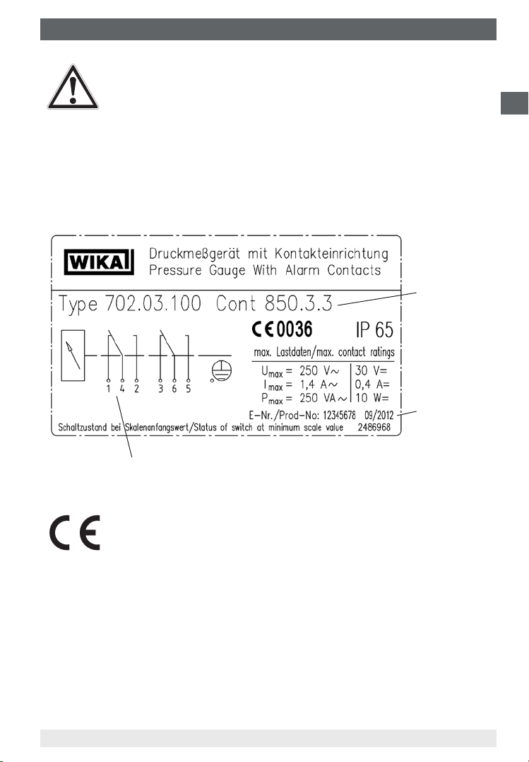
2.5 Labelling / safety marks
Product label
GB
Type of
contact
Date of
manufacture
Pin assignment
Explanation of symbols
CE, Communauté Européenne
Instruments bearing this mark comply with the relevant European
directives.
2367781.03 06/2013 GB/D/F/E
WIKA operating instructions dierential pressure gauge, model 702.03.100 7
Page 8
3. Specications
3. Specications
Specications DELTA-comb model 702.03.100
GB
Nominal size mm Dierential pressure indication: Ø 100
mm Working pressure indication: Ø 23
Accuracy class Dierential pressure indication: 2.5
Working pressure indication: 4
Scale ranges per EN 837 bar Dierential pressure: 0 ... 0.25 to 0 ... 6
bar Working pressure: 0 ... 25
Max. working pressure
(stat.)
Overpressure safety bar Either side max. 25
Permissible temperature °C Ambient: -10 ... +70
Ingress protection IP 65 per EN 60529/IEC 529
Media chamber wetted GD-AISi 12 (Cu) 3.2982, black lacquered
Process connections wetted 2 x G 1/4 female, lower mount (LM), in-line, centre
Pressure elements wetted Dierential pressure: Compression spring from
Transmission parts wetted Stainless steel 1.4305, FPM/FKM (option: NBR)
Sealings wetted FPM/FKM (option: NBR)
Movement Cu-alloy, wear parts argentan
Dial Dierential pressure indication: Aluminium, blue,
Pointer Dierential pressure indication: Adjustable pointer,
Zero adjustment for
dierential pressure
indication
Case GD-AISi 12 (Cu) 3.2982, black lacquered
Window PMMA
Weight kg approx. 1.4
bar 25
°C Medium: max. +90
distance 26 mm
stainless steel 1.4310 or FD SiCr EN 10270-2
and separating diaphragm from FPM/FKM
fabric-reinforced (option: NBR)
Working pressure: Bourdon tube from Cu-alloy
white lettering
Working pressure indication: Plastic, white, black
lettering
aluminium, white
Working pressure indication: Plastic, black
By means of adjustable pointer
2367781.03 06/2013 GB/D/F/E
WIKA operating instructions dierential pressure gauge, model 702.03.1008
Page 9
3. Specications / 4. Design and function
Electrical contact
Type of contact Micro switch
Contact functions Single (change-over) contact
850.3
Load data Voltage AC Voltage DC
U max. 250 V 30 V
I max. 5 A 0.4 A
P max. 250 VA 10 W
Switch point setting from the outside at assistant scale by means of adjustment
screw(s)
Setting range from 10 % to 100 % of the full scale value
Switch point
reproducibility
Switch hysteresis max. 5 % of the full scale value (option: max. 2.5 %)
Electrical connection via cable gland M20 x 1.5 with 1 m free cable end
≤ 1.6 %
Double (change-over) contact
850.3.3
For further specications see the corresponding product label, WIKA data sheet
and the order documentation.
4. Design and function
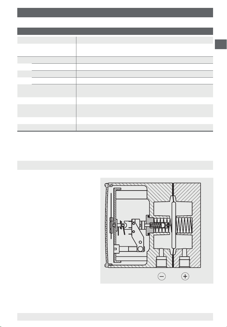
4.1 Description
The ⊕ and ⊖ media chambers
are separated by an elastic diaphragm. The dierential pressure leads to an axial deection
of the the diaphragm against
the measuring range spring.
The deection, which is
proportional to the dierential
pressure, is transmitted to
a movement and in addition
to the plungers of the micro
switches via a pressure-tight
and low friction link.
GB
2122740.01
4.2 Scope of delivery
Cross-check scope of delivery with delivery note.
2367781.03 06/2013 GB/D/F/E
WIKA operating instructions dierential pressure gauge, model 702.03.100 9
Page 10
5. Transport, packaging ... / 6. Commissioning, operation
5. Transport, packaging and storage
5.1 Transport
GB
Check the dierential pressure gauge for any damage that may have been
caused by transport. Obvious damage must be reported immediately.
5.2 Packaging
Do not remove packaging until just before mounting.
Keep the packaging as it will provide optimum protection during transport (e.g.
change in installation site, sending for repair).
5.3 Storage
Permissible conditions at the place of storage
Storage temperature: -20 ... +60 °C
In order to prevent damage, the following points should be noted for the
storage of the pressure gauges:
■
Leave the pressure gauges in their original packaging
■
Following any possible removal of the measuring instruments, e.g. for testing,
the instrument should again be stored in its original packaging
Avoid exposure to the following factors:
■
Direct sunlight or proximity to hot objects
■
Mechanical vibration, mechanical shock (putting it down hard)
■
Soot, vapour, dust, humidity and corrosive gases
■
Potentially explosive environments, ammable atmosphere
WARNING!
Before storing the instrument (following operation), any residual
media must be removed. This is of particular importance if the
medium is hazardous to health, e.g. caustic, toxic, carcinogenic,
radioactive, etc.
6. Commissioning, operation
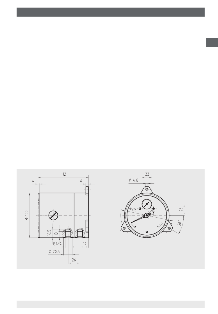
6.1 Mechanical connection
■
In accordance with the general technical regulations for pressure gauges (e.g.
EN 837-2 "Selection and installation recommendations for pressure gauges").
■
Process connections 2 x G 1/4 female, lower mount (LM), in-line, centre
distance 26 mm, operating position NL 90 (nominal position) per DIN 16257
(i.e. vertical dial), design the threads of the pressure connection in accordance
with EN 837-3 (section 7.3.2).
WIKA operating instructions dierential pressure gauge, model 702.03.10010
2367781.03 06/2013 GB/D/F/E
Page 11
6. Commissioning, operation
■
Prior to the installation of the pressure gauge, clean the measuring lines
thoroughly by tapping and blowing or rinsing
■
Protect measuring instruments from contamination and high temperature
changes!
■
The pressure gauge must be mounted free from vibration and should be
aligned so that it is easy to read. It is recommended that an isolation device is
interposed between the pressure tapping point and the pressure gauge, which
will enable the replacement of the pressure gauge and a zero point check while
the plant is running. The instruments should be protected against coarse dirt
and wide uctuations in ambient temperature.
■
Correct sealing of the connections must be made using suitable at gaskets,
sealing rings or WIKA prole sealings. In order to orientate the gauge so that
the on-site display can be read as well as possible, a clamp socket or union nut
should be used. When screwing on and unscrewing the pressure gauges they
should not be gripped by the case, but rather only on the spanner ats of the
connection!
Wall mounting
Mounting using three integrally cast mounting lugs
GB
2367781.03 06/2013 GB/D/F/E
WIKA operating instructions dierential pressure gauge, model 702.03.100 11
2123541.01
Page 12
6. Commissioning, operation
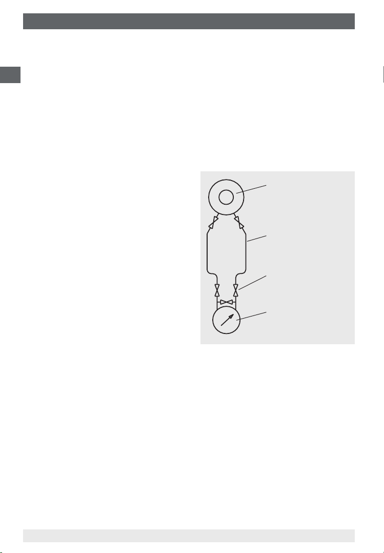
Measuring assemblies
The preferred measuring assemblies for various possible applications are
specied in DIN 19216.
GB
The following schematic diagram shows a recommended assembly for liquid
media. As throttling devices, dierential pressure transducers should be provided
in accordance with DIN 1952 (issue 07.82), now replaced by EN 5167/1.
The dierential pressure lines must be made from metal, their bore must not
be less than 4 mm and the eective length between the valve manifold and the
dierential pressure gauge must be at least 500 mm.
In addition, the length and the bore of
the pressure lines should be such that,
with cold lines, the response time of
the pressure gauge is not more than 5
seconds.
The connections of the dierential
Dierential pressure
transducer
(throttling device in the
process line)
Dierential pressure
line
pressure lines must be welded, brazed or
screwed using metal sealing elements.
Shut-o valves
Shut-o valves in dierential pressure
(valve manifold)
lines must only be operated using tools.
Dierential pressure
instrument
(Dierential pressure
gauge DELTA-comb)
6.2 Electrical connection
■
The electrical connection must only be made by qualied skilled personnel.
■
Connection details and switching functions are given on the product label.
Connection terminals and earth terminal are appropriately marked.
■
The mains connection lines to be provided must be dimensioned for maximum
instrument power consumption and comply with IEC 227 or IEC 245.
■
The instruments must be connected to the equipotential bonding of the plant.
Performance data (see „Specications“)
WIKA operating instructions dierential pressure gauge, model 702.03.10012
2367781.03 06/2013 GB/D/F/E
Page 13
6. Commissioning, operation
Safety instructions for installation
■
Follow the installation and safety instructions within the
operating instructions.
■
Install instruments in accordance with the manufacturer's
instructions and the valid standards and regulations.
■
The instruments do not provide for incorporated overcurrent protectors!
■
In order to prevent the contacts from welding through overload, suitable
protection systems must be implemented by the operator!
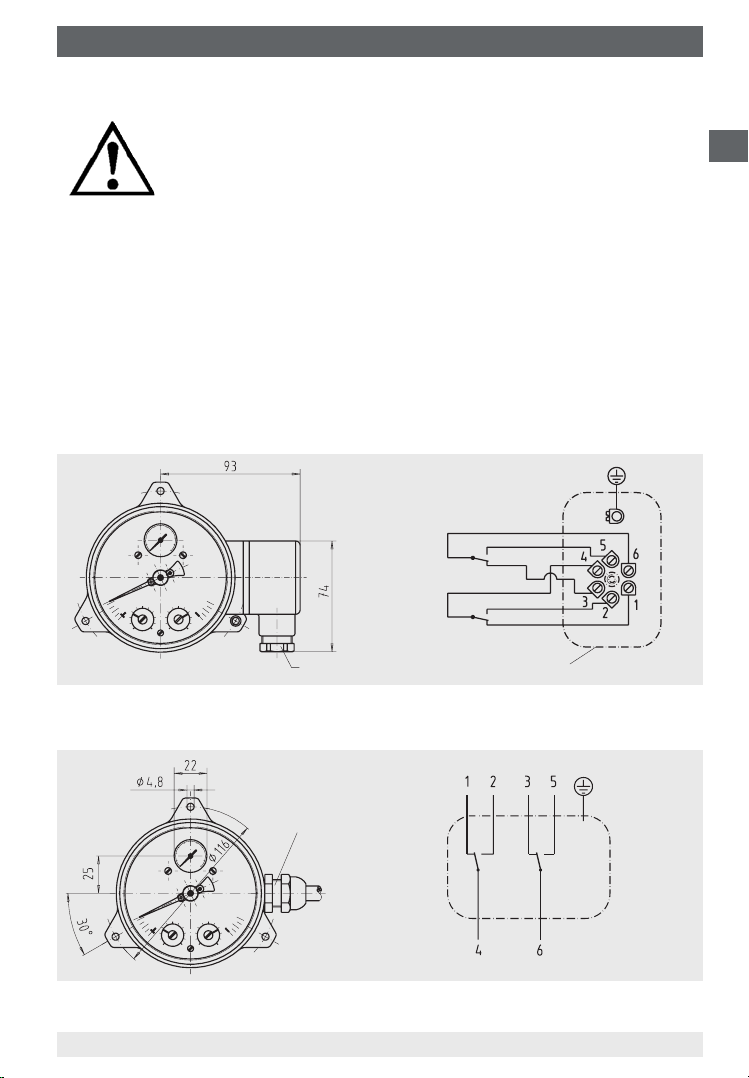
Precise wiring schemes can be seen in the following connection diagram. In
addition both the pin assignment and the required power supply are stated on
the product label of the case circumference.
Electrical connection via:
■
Terminal box or angular connector per DIN 43651
GB
2157306.0X2123568.0X
850.33 2nd contact
850.3 1st contact
M20 x 1.5
Cable terminal box
or electrical connection via:
■
Cable gland and cable
Cable gland M20 x 1.5
with 1 m cable
850.3 1st
contact
2367781.03 06/2013 GB/D/F/E
WIKA operating instructions dierential pressure gauge, model 702.03.100 13
850.33
2nd
contact
2162679.01
2162679.0X
Page 14

6. Commissioning, operation
Information
For the safety circuit, which will switch o the heating if the
GB
6.3 Switch point setting and zero point test
The switch points are set at the factory when the set points are given.
The adjustment of the switch point is made by the adjustment screws accessible
from the front. An assistant scale over 270 ∢° enables a relatively accurate
adjustment of the switch points and indicates the set point that is currently
adjusted.
For contact adjustment, the vent plugs in the snap-in disc should be removed. By
turning the contact adjustment screws using a screwdriver the desired switch point
can be set.
If an even more accurate switch point setting is required, a reference standard
should be used for the adjustment.
Afterwards, the vent plugs should be pressed back into the snap-in disc.
Following the setting and the testing of the switch point in the equipment, the
instrument must be sealed and the set value marked on the instrument.
Zero point test
By opening a pressure compensating valve (see point 7.1 on page 15) a zero
point check during the running process is possible.
The medium ows from the higher-pressure side towards the opposite side and
the dierential pressure at the gauge drops to zero.
steam generator falls below the minimum ow, only the normally
open contact of the changeover switch should be connected (i.e.
with Δp = 0 open circuit)!
By opening the pressure compensating valve, the dierential pressure indicator
must drop to zero, i.e. into the area of the zero-point tolerance bar. The instrument
function is thus in order. With possible deviations, which are outside the tolerance
bar, a zero adjustment can be made using the standard built-in adjustable pointer.
To do this the snap-in disc should be lifted o,
using a screwdriver in the appropriate impression/
recess.
The zero adjustment is achieved by turning the
slotted screw on the adjustable pointer.
Afterwards, the snap-in disc should replaced on
the case.
The dierential pressure will be displayed again
Slotted screw
as soon as the pressure compensating valve is
closed once more.
WIKA operating instructions dierential pressure gauge, model 702.03.10014
2367781.03 06/2013 GB/D/F/E
Page 15
6. Commissioning, operation / 7. Options and accessories
Commissioning
During the commissioning process pressure surges must be avoided at all costs.
Open the shut-o valves slowly.
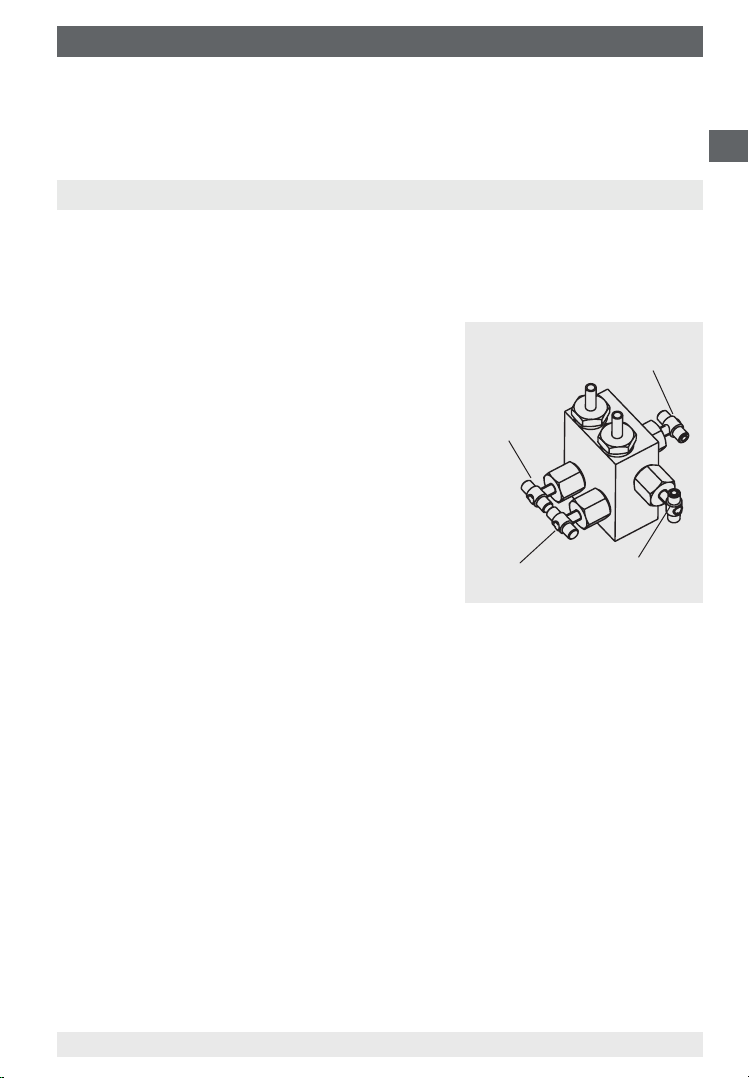
7. Options and accessories
7.1 4-way valve manifold
■
Isolation of the ⊕ and ⊖ process lines for removing or testing the measuring
instrument without interrupting the running process operation.
Protection of the unit against excessive
overpressure loading, such as in pressure
tests and undened operating conditions
(including intermittent shutdown).
Pressure compensating valve
GB
■
Pressure compensation for zero point
checking with running processes, and avoid-
Shut-o valve
⊕ side
ing one-sided overpressure loading during
start-up and operation phases (with opened
pressure compensating valve).
■
Venting the measuring lines with liquid media and ushing of the measuring lines, in
order to remove contamination.
Shut-o valve
⊖ side
Vent valve
Specications for handling
■
Sequence of operations to start measurement
1. Open the pressure compensating valve (middle valve spindle)
2. Open the shut-o valve for the negative media chamber (⊖, right-hand valve)
and the positive media chamber (⊕, left-hand valve)
3. Close the pressure compensating valve
■
Sequence of operations to ush/vent the measuring lines
1. Start: Open the shut-o valve for the ⊕ and ⊖ media chamber, open the
pressure compensating valve and vent valve
2. Finish: Close the pressure compensating valve and vent valve
■
Sequence of operations to nish measurement (also temporary shutdown)
1. Open the pressure compensating valve
2. Close the shut-o valve for the ⊕ and ⊖ media chamber
2367781.03 06/2013 GB/D/F/E
WIKA operating instructions dierential pressure gauge, model 702.03.100 15
Page 16
7. Options and accessories / 8. Maintenance
■
Sequence of operations to dismount the measuring instrument with a
running process
GB
1. Open the pressure compensating valve
2. Close the shut-o valve for the ⊕ and ⊖ media chamber
3. Open the vent valve
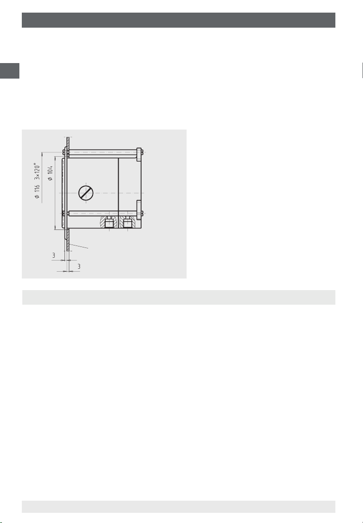
7.2 Panel mounting ange
Cutout
Panel
8. Maintenance
2123649.0X
The instruments are maintenance-free.
The indicator and switching function should be checked once or twice every year.
For this the instrument must be disconnected from the process to check with a
pressure testing device.
Repairs must only be carried out by the manufacturer.
WIKA operating instructions dierential pressure gauge, model 702.03.10016
2367781.03 06/2013 GB/D/F/E
Page 17

9. Dismounting, return and disposal
9. Dismounting, return and disposal
WARNING!
Residual media in dismounted measuring instruments can result
in a risk to persons, the environment and equipment.
Take sucient precautionary measures.
9.1 Dismounting
Only disconnect the measuring instrument once the system has been depressurised and the power disconnected!
If necessary, the measuring line must have strain relief. For pressure gauges with
diaphragm pressure elements, the clamping bolts of the upper and lower ange
must not be loosened.
9.2 Return
Wash or clean the dismounted measuring instrument before returning it, in order
to protect personnel and the environment from exposure to residual media.
9.3 Disposal
Incorrect disposal can put the environment at risk. Dispose of instrument
components and packaging materials in an environmentally compatible way and
in accordance with the country-specic waste disposal regulations.
GB
2367781.03 06/2013 GB/D/F/E
WIKA operating instructions dierential pressure gauge, model 702.03.100 17
Page 18
Appendix 1: EC declaration of conformity
GB
2367781.03 06/2013 GB/D/F/E
WIKA operating instructions dierential pressure gauge, model 702.03.10018
Page 19
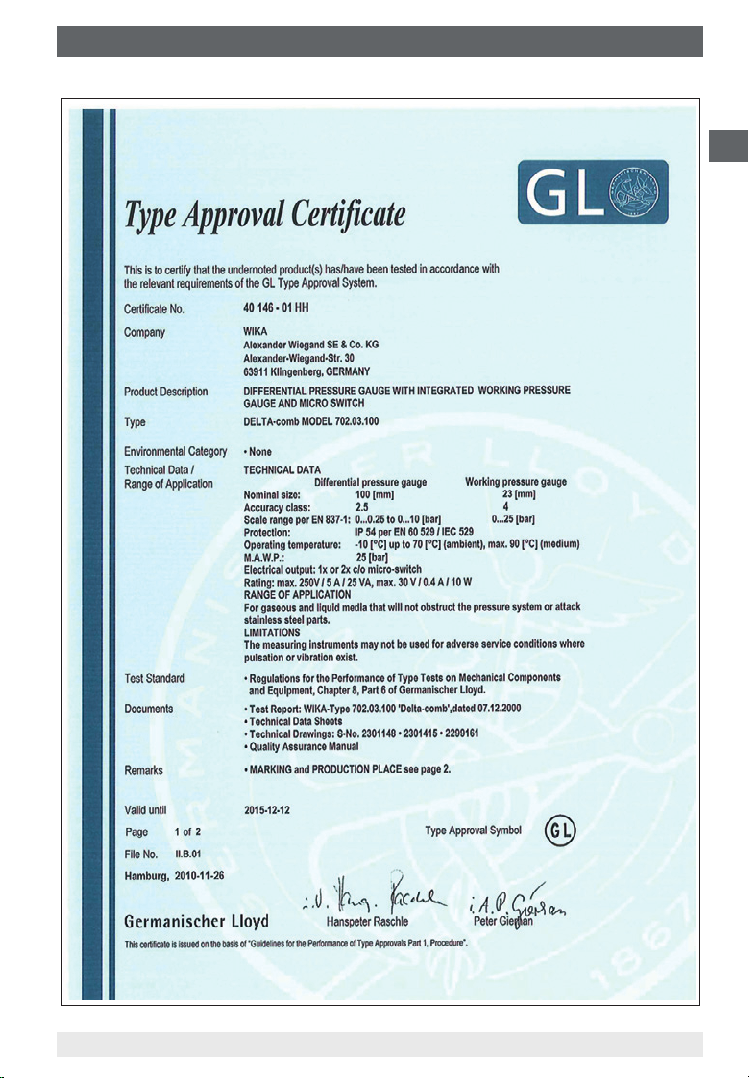
Appendix 2: Germanischer Lloyd approval
GB
2367781.03 06/2013 GB/D/F/E
WIKA operating instructions dierential pressure gauge, model 702.03.100 19
Page 20
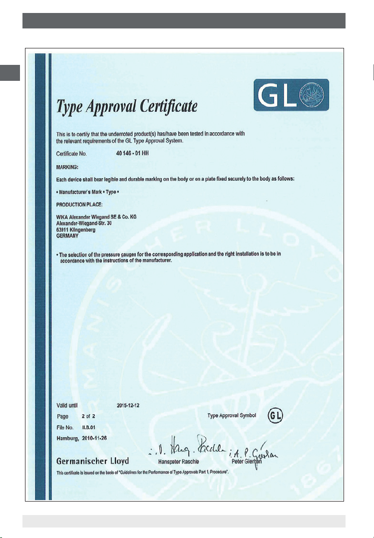
Appendix 2: Germanischer Lloyd approval
GB
2367781.03 06/2013 GB/D/F/E
WIKA operating instructions dierential pressure gauge, model 702.03.10020
Page 21

Inhalt
Inhalt
1. Allgemeines 22
2. Sicherheit 23
3. Technische Daten 26
4. Aufbau und Funktion 27
5. Transport, Verpackung und Lagerung 28
6. Inbetriebnahme, Betrieb 28
7. Optionen und Zubehör 33
8. Wartung 34
9. Demontage, Rücksendung und Entsorgung 35
Anlage 1: EG-Konformitätserklärung 36
Anlage 2: Zulassung Germanischer Lloyd 37
D
2367781.03 06/2013 GB/D/F/E
WIKA Betriebsanleitung Dierenzdruckmessgerät, Typ 702.03.100 21
Page 22

1. Allgemeines
1. Allgemeines
■
Das in der Betriebsanleitung beschriebene Dierenzdruckmessgerät wird nach
dem aktuellen Stand der Technik konstruiert und gefertigt.
Alle Komponenten unterliegen während der Fertigung strengen Qualitätsund Umweltkriterien. Unsere Managementsysteme sind nach ISO 9001 und
D
ISO 14001 zertiziert.
■
Diese Betriebsanleitung gibt wichtige Hinweise zum Umgang mit dem Gerät.
Voraussetzung für sicheres Arbeiten ist die Einhaltung aller angegebenen
Sicherheitshinweise und Handlungsanweisungen.
■
Die für den Einsatzbereich des Gerätes geltenden örtlichen Unfallverhütungsvorschriften und allgemeinen Sicherheitsbestimmungen einhalten.
■
Die Betriebsanleitung ist Produktbestandteil und muss in unmittelbarer Nähe
des Gerätes für das Fachpersonal jederzeit zugänglich aufbewahrt werden.
■
Das Fachpersonal muss die Betriebsanleitung vor Beginn aller Arbeiten sorgfältig durchgelesen und verstanden haben.
■
Die Haftung des Herstellers erlischt bei Schäden durch bestimmungswidrige
Verwendung, Nichtbeachten dieser Betriebsanleitung, Einsatz ungenügend
qualizierten Fachpersonals sowie eigenmächtiger Veränderung am Gerät.
■
Es gelten die allgemeinen Geschäftsbedingungen in den Verkaufsunterlagen.
■
Technische Änderungen vorbehalten.
■
Weitere Informationen:
- Internet-Adresse: www.wika.de / www.wika.com
- zugehöriges Datenblatt: PV 27.19
Symbolerklärung
WARNUNG!
… weist auf eine möglicherweise gefährliche Situation hin, die
zum Tod oder zu schweren Verletzungen führen kann, wenn sie
nicht gemieden wird.
Information
… hebt nützliche Tipps und Empfehlungen sowie Informationen
für einen ezienten und störungsfreien Betrieb hervor.
WIKA Betriebsanleitung Dierenzdruckmessgerät, Typ 702.03.10022
2367781.03 06/2013 GB/D/F/E
Page 23

1. Allgemeines / 2. Sicherheit
WARNUNG!
… weist auf eine möglicherweise gefährliche Situation im explosionsgefährdeten Bereich hin, die zum Tod oder zu schweren
Verletzungen führen kann, wenn sie nicht gemieden wird.
2. Sicherheit
WARNUNG!
Vor Montage, Inbetriebnahme und Betrieb sicherstellen, dass
das richtige Dierenzdruckmessgerät hinsichtlich Ausführung
und spezischen Messbedingungen ausgewählt wurde.
Verträglichkeit der druckbelasteten Werkstoe mit dem Messsto prüfen!
Die Belastungsgrenzen sind einzuhalten, um die Messgenauigkeit und die Lebensdauer zu gewährleisten.
Alle Arbeiten dürfen nur im spannungslosen Zustand erfolgen.
Bei Nichtbeachten können schwere Körperverletzungen und/
oder Sachschäden auftreten.
Weitere wichtige Sicherheitshinweise benden sich in den einzelnen Kapiteln dieser Betriebsanleitung.
2.1 Bestimmungsgemäße Verwendung
Dieses Dierenzdruckmessgerät wird vorzugsweise zur Überwachung
und Regelung von Dierenzdrücken an Filteranlagen, Pumpen und
Rohrleitungssystemen im Bereich der Heizungs-, Klima und Lüftungstechnik, der
Gebäudeautomation und dem Wassermanagement eingesetzt.
Geräte nach Richtlinie 94/9/EG (ATEX) dienen zur Druckmessung bei industriellen
Anwendungen in explosionsgefährdeten Bereichen.
D
Das Gerät ist ausschließlich für den hier beschriebenen bestimmungsgemäßen
Verwendungszweck konzipiert und konstruiert und darf nur dementsprechend
verwendet werden.
Ansprüche jeglicher Art aufgrund von nicht bestimmungsgemäßer Verwendung
sind ausgeschlossen.
2367781.03 06/2013 GB/D/F/E
WIKA Betriebsanleitung Dierenzdruckmessgerät, Typ 702.03.100 23
Page 24

2. Sicherheit
2.2 Personalqualikation
WARNUNG!
Verletzungsgefahr bei unzureichender Qualikation!
Unsachgemäßer Umgang kann zu erheblichen Personen- und
D
Fachpersonal
Das Fachpersonal ist aufgrund seiner fachlichen Ausbildung, seiner Kenntnisse
der Mess- und Regelungstechnik und seiner Erfahrungen sowie Kenntnis der
landesspezischen Vorschriften, geltenden Normen und Richtlinien in der Lage,
die beschriebenen Arbeiten auszuführen und mögliche Gefahren selbstständig zu
erkennen.
2.3 Sicherheitshinweise für Druckmessgeräte nach ATEX
Sachschäden führen.
■
Die in dieser Betriebsanleitung beschriebenen Tätigkeiten nur
durch Fachpersonal nachfolgend beschriebener Qualikation
durchführen lassen.
WARNUNG!
Die Nichtbeachtung dieser Inhalte und Anweisungen kann zum
Verlust des Explosionsschutzes führen.
WARNUNG!
Einsatzbedingungen und sicherheitstechnische Daten der
EG Baumusterprüfbescheinigung unbedingt beachten.
Druckmessgeräte über den Prozessanschluss erden!
2.4 Besondere Gefahren
WARNUNG!
Die Angaben der geltenden Baumusterprüfbescheinigung sowie
die jeweiligen landesspezischen Vorschriften zur Installation und
Einsatz in explosionsgefährdeten Bereichen (z. B. IEC 60079-14,
NEC, CEC) einhalten. Bei Nichtbeachten können schwere
Körperverletzungen und/oder Sachschäden auftreten.
WARNUNG!
Bei gefährlichen Messstoen wie z. B. Sauersto, Acetylen,
brennbaren oder giftigen Stoen, sowie bei Kälteanlagen,
Kompressoren etc. müssen über die gesamten allgemeinen
Regeln hinaus die jeweils bestehenden einschlägigen Vorschriften
beachtet werden.
WIKA Betriebsanleitung Dierenzdruckmessgerät, Typ 702.03.10024
2367781.03 06/2013 GB/D/F/E
Page 25

2. Sicherheit
WARNUNG!
Messstoreste in ausgebauten Messgeräten können zur
Gefährdung von Personen, Umwelt und Einrichtung führen.
Ausreichende Vorsichtsmaßnahmen ergreifen.
2.5 Beschilderung / Sicherheitskennzeichnungen
Typenschild
D
Kontakt-
Typ
Herstellungsdatum
Anschlussbelegung
Symbolerklärung
CE, Communauté Européenne
Geräte mit dieser Kennzeichnung stimmen überein mit den zutreenden europäischen Richtlinien.
2367781.03 06/2013 GB/D/F/E
WIKA Betriebsanleitung Dierenzdruckmessgerät, Typ 702.03.100 25
Page 26

3. Technische Daten
3. Technische Daten
Technische Daten DELTA-comb Typ 702.03.100
Nenngröße mm Dierenzdruckanzeige: Ø 100
mm Betriebsdruckanzeige: Ø 23
Genauigkeitsklasse Dierenzdruckanzeige: 2,5
D
Betriebsdruckanzeige: 4
Anzeigebereiche nach
EN 837
Max. Betriebsdruck (stat.) bar 25
Überlastbarkeit bar ein-, beid- und wechselseitig max. 25
Zulässige Temperatur °C Umgebung: -10 ... +70
Schutzart IP 65 nach EN 60529/IEC 529
Messstokammer messsto-
Prozessanschlüsse messsto-
Messglieder messsto-
Übertragungsteile messsto-
Dichtungen messsto-
Zeigerwerk CU-Legierung, Laufteile Neusilber
Zierblatt Dierenzdruckanzeige: Aluminium, blau,
Zeiger Dierenzdruckanzeige: Verstellzeiger, Aluminium
Nullpunktkorrektur für
Dierenzdruckanzeige
Gehäuse GD-AISi 12 (Cu) 3.2982, schwarz lackiert
Sichtscheibe PMMA
Gewicht kg ca. 1,4
bar Dierenzdruck: 0 ... 0,25 bis 0 ... 6
bar Betriebsdruck: 0 ... 25
°C Messsto: max. +90
GD-AISi 12 (Cu) 3.2982, schwarz lackiert
berührt
2 x G 1/4 Innengewinde, Anschlusslage unten,
berührt
berührt
berührt
berührt
hintereinander, Achsabstand 26 mm
Dierenzdruck: Druckfeder aus CrNi-Stahl
1.4310 oder FD SiCr EN 10270-2 und Trennmembran aus FPM/FKM
gewebeverstärkt (Option: NBR)
Betriebsdruck: Rohrfeder aus Cu-Legierung
CrNi-Stahl 1.4305, FPM/FKM (Option: NBR)
FPM/FKM (Option: NBR)
Skalierung weiß
Betriebsdruckanzeige: Kunststo, weiß,
Skalierung schwarz
weiß
Betriebsdruckanzeige: Kunststo, schwarz
über Verstellzeiger
2367781.03 06/2013 GB/D/F/E
WIKA Betriebsanleitung Dierenzdruckmessgerät, Typ 702.03.10026
Page 27

3. Technische Daten / 4. Aufbau und Funktion
Elektrischer Kontakt
Kontaktart Mikroschalter
Kontaktfunktionen Einfach-Wechsler 850.3 Zweifach-Wechsler 850.3.3
Lastdaten Wechselspannung Gleichspannung
U max. 250 V 30 V
I max. 5 A 0,4 A
P max. 250 VA 10 W
Schaltpunkteinstellung von außen an Hilfsskala über Einstellschraube(n)
Einstellbereich von 10 % bis 100 % des Skalenendwertes
Schaltpunktreprodu-
zierbarkeit
Schalthysterese max. 5 % vom Skalenendwert (Option: max. 2,5 %)
Elektrischer Anschluss über Kabelverschraubung M20 x 1,5 mit 1 m freiem Kabelende
≤ 1,6 %
Weitere technische Daten siehe jeweiliges Typenschild, WIKA-Datenblatt und
Bestellunterlagen.
4. Aufbau und Funktion
4.1 Beschreibung
Die ⊕- und ⊖-Messstokammern sind durch eine elastische Membrane getrennt.
Der Dierenzdruck bewirkt eine
axiale Auslenkung (Messweg)
der Membrane gegen die
Messbereichsfeder.
Der dem Dierenzdruck
proportionale Messweg
wird über eine Schubstange
druckdicht und reibungsarm auf
ein Zeigerwerk und zusätzlich
an die Stößel der Mikroschalter
übertragen.
D
2122740.01
4.2 Lieferumfang
Lieferumfang mit dem Lieferschein abgleichen.
2367781.03 06/2013 GB/D/F/E
WIKA Betriebsanleitung Dierenzdruckmessgerät, Typ 702.03.100 27
Page 28

5. Transport, Verpackung ... / 6. Inbetriebnahme, Betrieb
5. Transport, Verpackung und Lagerung
5.1 Transport
Dierenzdruckmessgerät auf eventuell vorhandene Transportschäden
untersuchen. Oensichtliche Schäden unverzüglich mitteilen.
D
5.2 Verpackung
Verpackung erst unmittelbar vor der Montage entfernen.
Die Verpackung aufbewahren, denn diese bietet bei einem Transport einen
optimalen Schutz (z. B. wechselnder Einbauort, Reparatursendung).
5.3 Lagerung
Zulässige Bedingungen am Lagerort
Lagertemperatur: -20 ... +60 °C
Um Schäden zu vermeiden, sind für die Lagerung der Druckmessgeräte
folgende Punkte zu beachten:
■
Druckmessgeräte in der Originalverpackung belassen
■
Nach einer eventuellen Entnahme der Messgeräte für z. B. Prüfungen, sollte
das Gerät wieder in der Originalverpackung eingelagert werden
Vermeiden Sie folgende Einüsse:
■
Direktes Sonnenlicht oder Nähe zu heißen Gegenständen
■
Mechanische Vibration, mechanischer Schock (hartes Aufstellen)
■
Ruß, Dampf, Staub, Feuchtigkeit und korrosive Gase
■
Explosionsgefährdete Umgebung, entzündliche Atmosphäre
WARNUNG!
Vor der Einlagerung des Gerätes müssen alle ggf. anhaftenden
Messstoreste entfernt werden. Dies ist besonders wichtig, wenn
das Medium gesundheitsgefährdend ist, wie z. B. ätzend, giftig,
krebserregend, radioaktiv, usw.
6. Inbetriebnahme, Betrieb
6.1 Mechanischer Anschluss
■
Entsprechend den allgemeinen technischen Regeln für Druckmessgeräte
(z. B. EN 837-2 "Auswahl- und Einbauempfehlungen für Druckmessgeräte").
■
Prozessanschlüsse 2 x G 1/4 lnnengewinde, Anschlusslage unten,
hintereinander, Achsabstand 26 mm, Gebrauchslage NL 90 nach DIN 16257
(d.h. Zierblatt senkrecht), Gewinde der Anschlusszapfen vorzugsweise nach
EN 837-3 (Abschnitt 7.3.2) ausführen.
WIKA Betriebsanleitung Dierenzdruckmessgerät, Typ 702.03.10028
2367781.03 06/2013 GB/D/F/E
Page 29

6. Inbetriebnahme, Betrieb
■
Messleitungen vor der Gerätemontage gründlich durch Abklopfen und
Ausblasen oder Durchspülen reinigen
■
Messgeräte vor Verschmutzung und starken Temperaturschwankungen
schützen!
■
Das Druckmessgerät muss erschütterungsfrei befestigt werden und soll gut
ablesbar angeordnet sein. Es empehlt sich, zwischen Druckentnahmestelle
und Druckmessgerät eine Absperrvorrichtung zwischenzuschalten, die einen
Austausch des Messgerätes und eine Nullpunktkontrolle bei laufender Anlage
ermöglicht. Die Geräte sind vor grober Verschmutzung und starken Schwankungen der Umgebungstemperatur zu schützen.
■
Zur Abdichtung der Anschlüsse sind Flachdichtungen, Dichtlinsen oder
WIKA-Proldichtungen einzusetzen. Um das Druckmessgerät in die Stellung
zu bringen, in der sich die örtliche Anzeige am besten ablesen lässt, ist ein
Anschluss mit Spannmue oder Überwurfmutter zu empfehlen. Beim Ein- und
Ausschrauben dürfen die Druckmessgeräte nicht am Gehäuse angezogen
werden, sondern nur an den Schlüsselächen des Anschlussstutzens!
Wandmontage
Befestigung über drei angegossene Befestigungslaschen
D
2367781.03 06/2013 GB/D/F/E
WIKA Betriebsanleitung Dierenzdruckmessgerät, Typ 702.03.100 29
2123541.01
Page 30

6. Inbetriebnahme, Betrieb
Messanordnungen
Die zu bevorzugenden Messanordnungen für verschiedene Einsatzmöglichkeiten
sind in DIN 19216 beschrieben.
Die nachfolgende Prinzipdarstellung zeigt eine empfohlene Anordnung bei
üssigen Messstoen. Als Drosselgeräte sind Wirkdruckgeber nach DIN 1952
(Ausgabe 07.82) ersetzt durch EN 5167/1 vorzusehen.
D
Die Wirkdruckleitungen müssen aus Metall gefertigt sein, ihre lichte Weite darf
4 mm nicht unterschreiten und die gestreckte Länge zwischen Ventilblock und
Dierenzdruckmessgerät muss mindestens 500 mm betragen.
Außerdem sind Länge und lichte Weite
der Wirkdruckleitungen so zu bemessen,
dass bei kalter Leitung die Ansprechzeit
des Druckmessgerätes nicht mehr als
Wirkdruckgeber
(Drosselgerät in der
Prozessleitung)
5 Sekunden beträgt.
Die Verbindungen der Wirkdruckleitungen
Wirkdruckleitung
müssen verschweißt, hartgelötet oder mit
metallischen Dichtelementen verschraubt
werden.
Absperrarmaturen
(Ventilblock)
Absperrarmaturen in Wirkdruckleitungen
dürfen nur mit Werkzeugen zu betätigen
sein.
Wirkdruckmessgerät
(Dierenzdruckmessgerät DELTA-comb)
6.2 Elektrischer Anschluss
■
Der elektrische Anschluss darf nur durch qualiziertes Fachpersonal erfolgen.
■
Die Belegung der Anschlüsse und die Schaltfunktionen sind auf dem Typenschild am Gerät angegeben und die Anschlussklemmen sowie die Erdungsklemme sind entsprechend gekennzeichnet.
■
Die vorgesehenen Netzanschlussleitungen müssen für die größte Stromaufnahme des Gerätes bemessen sein und IEC 227 oder IEC 245 entsprechen.
■
Die Geräte sind in den Potenzialausgleich der Anlage mit einzubeziehen.
Leistungsdaten (siehe „Technische Daten“)
WIKA Betriebsanleitung Dierenzdruckmessgerät, Typ 702.03.10030
2367781.03 06/2013 GB/D/F/E
Page 31

6. Inbetriebnahme, Betrieb
Sicherheitshinweise bei Installation
■
Installations- und Sicherheitshinweise der Betriebsanleitung
beachten.
■
Geräte gemäß Herstellerangaben und den gültigen Normen
und Regeln installieren.
■
In den Geräten sind keine Überstrom-Schutzeinrichtungen eingebaut!
■
Um ein Verschweißen der Schalter durch Überlast zu verhindern, sind geeignete Schutzeinrichtungen vom Anwender vorzusehen!
Die genauen Anschlussbelegungen können dem nachfolgenden
Anschlussschema entnommen werden. Zusätzlich sind Anschlussbelegung und
erforderliche Hilfsenergie auf dem Typenschild am Gehäuseumfang vermerkt.
Elektrischer Anschluss über:
■
Kabeldose oder Winkelstecker nach DIN 43651
D
2157306.0X2123568.0X
850.33 2. Kontakt
850.3 1. Kontakt
M20 x 1,5
Kabelanschlussdose
oder elektrischer Anschluss über:
■
Kabelverschraubung und Kabel
Kabelverschraubung
M20 x 1,5
mit 1 m Kabel
850.3
1. Kontakt
2367781.03 06/2013 GB/D/F/E
WIKA Betriebsanleitung Dierenzdruckmessgerät, Typ 702.03.100 31
850.33
2. Kontakt
2162679.01
2162679.0X
Page 32

6. Inbetriebnahme, Betrieb
Information
Für den Sicherheitsstromkreis, der bei Unterschreiten des
Mindestdurchusses die Beheizung des Dampferzeugers
abschalten soll, darf nur der Schließer des Umschaltkontaktes
angeschlossen werden (d.h. der bei Δp = 0 oene Kreis)!
D
6.3 Schaltpunkteinstellung und Nullpunktüberprüfung
Bei Angabe der Sollwerte werden werkseitig die Schaltpunkte eingestellt.
Die Schaltpunktverstellung erfolgt über frontseitig zugängliche Einstellschrau-
ben. Eine Hilfsskala über 270 ∢° ermöglicht eine relativ genaue Schaltpunktjustierung und zeigt den momentan eingestellten Sollwert.
Zur Kontaktverstellung sind die Verschlussstopfen in der Schnappscheibe zu
entfernen. Durch Drehen der Kontakteinstellschrauben mittels Schrauben-dreher
kann gewünschter Schaltpunkt eingestellt werden.
Wird eine noch genauere Schaltpunkteinstellung gewünscht, sollte ein Prüfnormal
zur Justage verwendet werden.
Anschließend sind die Verschlussstopfen in der Schnappscheibe wieder einzudrücken.
Nach der Einstellung und Überprüfung des Schaltpunktes in der Anlage ist das
Gerät zu verplomben und der eingestellte Wert am Gerät zu vermerken.
Nullpunktüberprüfung
Durch Önen eines Druckausgleichsventiles (siehe Punkt 7.1 auf Seite 33) wird
eine Nullpunktkontrolle im laufenden Betriebsprozess ermöglicht.
Der Messsto strömt von der Seite höheren Druckes nach der Gegenseite und
der Dierenzdruck am Messgerät fällt auf Null.
Durch Önen des Druckausgleichsventiles muss die Dierenzdruckanzeige auf
Null, d.h. in den Bereich des Nullpunkt-Toleranzbalkens gehen. Die Gerätefunktion
ist damit in Ordnung. Bei möglichen Abweichungen, die außerhalb des Toleranzbalkens liegen, kann eine Nullpunktkorrektur über den standardmäßig eingebauten Verstellzeiger erfolgen.
Dazu ist die Schnappscheibe mittels Schraubendreher an der am Umfang angebrachten Einprägung/Aussparung abzuheben.
Die Nullpunktverstellung wird durch ein Verdrehen
der Schlitzschraube am Verstellzeiger erreicht.
Anschließend ist die Schnappscheibe wieder auf
dem Gehäuse aufzubringen.
Der Dierenzdruck wird wieder angezeigt, sobald
Schlitzschraube
das Druckausgleichsventil wieder geschlossen
wird.
WIKA Betriebsanleitung Dierenzdruckmessgerät, Typ 702.03.10032
2367781.03 06/2013 GB/D/F/E
Page 33

6. Inbetriebnahme, Betrieb / 7. Optionen und Zubehör
Inbetriebnahme
Bei Inbetriebnahme Druckstöße unbedingt vermeiden, Absperrventile langsam
önen.
7. Optionen und Zubehör
7.1 Vierfach-Ventilblock
■
Absperrung der ⊕- und ⊖-Prozessleitung zur Demontage oder Prüfung des
Messgerätes ohne Störung des laufenden Betriebsprozesses.
Schutz des Gerätes gegen unzulässige
Überdruckbelastung, wie z. B. bei
Druckprüfungen und undenierten
Betriebsverhältnissen (auch zeitweiliger
Stilllegung).
Absperrventil
■
Druckausgleich zur Nullpunktkontrolle
⊕-Seite
bei laufendem Prozess sowie Vermeidung
einseitiger Überdruckbelastung während der
Anfahr- bzw. Betriebsphase (bei geönetem
Druckausgleichsventil).
■
Entlüftung der Messleitungen bei üssigen
Messstoen und Spülung der Messleitungen, um Verunreinigungen zu entfernen.
Absperrventil
⊖-Seite
Angaben zum Handling
■
Arbeitsgangfolge zum Messanfang
1. Druckausgleichsventil (mittlere Ventilspindel) önen
2. Absperrventil der Minus-Messstokammer (⊖, rechtes Ventil) und der PlusMessstokammer (⊕, linkes Ventil) önen
3. Druckausgleichsventil schließen
Druckausgleichsventil
Entlüftungsventil
D
■
Arbeitsgangfolge zum Spülen/Entlüften der Messleitungen
1. Anfang: Absperrventil der ⊕- und ⊖-Messstokammer önen, Druckaus-
gleichsventil und Entlüftungsventil önen
2. Ende: Druckausgleichsventil und Entlüftungsventil schließen
■
Arbeitsgangfolge zu Messende (auch zeitweise Stilllegung)
1. Druckausgleichsventil önen
2. Absperrventil der ⊕- und ⊖-Messstokammer schließen
2367781.03 06/2013 GB/D/F/E
WIKA Betriebsanleitung Dierenzdruckmessgerät, Typ 702.03.100 33
Page 34

7. Optionen und Zubehör / 8. Wartung
■
Arbeitsgangfolge zur Demontage des Messgerätes bei laufenden Prozess
1. Druckausgleichsventil önen
2. Absperrventil der ⊕- und ⊖-Messstokammer schließen
3. Entlüftungsventil önen
D
7.2 Befestigungsrand für Schalttafelmontage
2123649.0X
Ausschnitt
Schalttafel
8. Wartung
Die Geräte sind wartungsfrei.
Eine Überprüfung der Anzeige und der Schaltfunktion sollte etwa 1 bis 2 mal pro
Jahr erfolgen. Dazu ist das Gerät vom Prozess zu trennen und mit einer Druckprüfvorrichtung zu kontrollieren.
Reparaturen sind ausschließlich vom Hersteller durchzuführen.
WIKA Betriebsanleitung Dierenzdruckmessgerät, Typ 702.03.10034
2367781.03 06/2013 GB/D/F/E
Page 35

9. Demontage, Rücksendung und Entsorgung
9. Demontage, Rücksendung und Entsorgung
WARNUNG!
Messstoreste in ausgebauten Messgeräten können zur
Gefährdung von Personen, Umwelt und Einrichtung führen.
Ausreichende Vorsichtsmaßnahmen ergreifen.
9.1 Demontage
Messgerät nur im drucklosen und spannungsfreiem Zustand demontieren!
Gegebenenfalls muss die Messleitung entspannt werden. Bei Druckmessgeräten
mit Plattenfedermessglied dürfen die Spannschrauben des Ober- und Unteransches nicht gelöst werden.
9.2 Rücksendung
Ausgebautes Messgerät vor der Rücksendung spülen bzw. säubern, um
Mitarbeiter und Umwelt vor Gefährdung durch anhaftende Messstoreste zu
schützen.
9.3 Entsorgung
Durch falsche Entsorgung können Gefahren für die Umwelt entstehen.
Gerätekomponenten und Verpackungsmaterialien entsprechend den
landesspezischen Abfallbehandlungs- und Entsorgungsvorschriften
umweltgerecht entsorgen.
D
2367781.03 06/2013 GB/D/F/E
WIKA Betriebsanleitung Dierenzdruckmessgerät, Typ 702.03.100 35
Page 36

Anlage 1: EG-Konformitätserklärung
D
2367781.03 06/2013 GB/D/F/E
WIKA Betriebsanleitung Dierenzdruckmessgerät, Typ 702.03.10036
Page 37

Anlage 2: Zulassung Germanischer Lloyd
D
2367781.03 06/2013 GB/D/F/E
WIKA Betriebsanleitung Dierenzdruckmessgerät, Typ 702.03.100 37
Page 38

Anlage 2: Zulassung Germanischer Lloyd
D
2367781.03 06/2013 GB/D/F/E
WIKA Betriebsanleitung Dierenzdruckmessgerät, Typ 702.03.10038
Page 39

Sommaire
Sommaire
1. Généralités 40
2. Sécurité 41
3. Spécications 44
4. Conception et fonction 45
5. Transport, emballage et stockage 46
6. Mise en service, exploitation 46
7. Options et accessoires 51
8. Entretien 52
9. Démontage, retour et mise au rebut 53
Annexe 1 : Déclaration de conformité CE 18
Annexe 2: Homologation Germanischer Lloyd 19
F
2367781.03 06/2013 GB/D/F/E
WIKA Mode d'emploi manomètre pour pression diérentielle, type 702.03.100 39
Page 40

1. Généralités
1. Généralités
■
Le manomètre de pression diérentielle décrit dans le mode d'emploi est
conçu et fabriqué selon les dernières technologies en vigueur. Tous les
composants sont soumis à des critères de qualité et d'environnement stricts
durant la fabrication. Nos systèmes de gestion sont certiés selon ISO 9001 et
ISO 14001.
■
Ce mode d'emploi donne des indications importantes concernant l'utilisation
F
de l'instrument. Il est possible de travailler en toute sécurité avec ce produit en
respectant toutes les consignes de sécurité et d'utilisation.
■
Respecter les prescriptions locales de prévention contre les accidents et les
prescriptions générales de sécurité en vigueur pour le domaine d'application
de l'instrument.
■
Le mode d'emploi fait partie de l'instrument et doit être conservé à proximité
immédiate de l'instrument et accessible à tout moment pour le personnel
qualié.
■
Le personnel qualié doit, avant de commencer toute opération, avoir lu
soigneusement et compris le mode d'emploi.
■
La responsabilité du fabricant n'est pas engagée en cas de dommages
provoqués par une utilisation non conforme à l'usage prévu, de non respect de
ce mode d'emploi, d'utilisation de personnel peu qualié de même qu'en cas
de modications de l'instrument eectuées par l'utilisateur.
■
Les conditions générales de vente mentionnées dans les documents de vente
s'appliquent.
■
Sous réserve de modications techniques.
■
Pour obtenir d'autres informations:
- Consulter notre site Internet : www.wika.fr
- Fiche technique correspondante : PV 27.19
Explication des symboles
AVERTISSEMENT!
… indique une situation présentant des risques susceptibles de
provoquer la mort ou des blessures graves si elle n'est pas évitée.
Information
… met en exergue les conseils et recommandations utiles
de même que les informations permettant d'assurer un
fonctionnement ecace et normal.
WIKA Mode d‘emploi manomètre pour pression diérentielle, type 702.03.10040
2367781.03 06/2013 GB/D/F/E
Page 41

1. Généralités / 2. Sécurité
AVERTISSEMENT!
… indique une situation en zone explosive présentant des
risques susceptibles de provoquer la mort ou des blessures
graves si elle n'est pas évitée.
2. Sécurité
AVERTISSEMENT!
Avant le montage, la mise en service et le fonctionnement,
s'assurer que le manomètre pour pression diérentielle a été
choisi de façon adéquate, en ce qui concerne la plage de
mesure, la version et les conditions de mesure spéciques.
Vérier si les matériaux soumis à la pression sont compatibles
avec le uide de mesure !
Les limites de surpression admissible sont à respecter an
d'assurer la précision et la durée de vie.
Toutes les interventions doivent être eectuées hors tension.
Un non respect de cette consigne peut entraîner des blessures
corporelles graves et/ou des dégâts matériels.
Vous trouverez d'autres consignes de sécurité dans les sections
individuelles du présent mode d'emploi.
2.1 Utilisation conforme à l'usage prévu
Ce manomètre pour pression diérentielle est utilisé particulièrement pour la
surveillance et le contrôle de pressions diérentielles dans des systèmes de
ltres, des systèmes de pompes et de tuyauteries dans le secteur du chauage,
de la ventilation et de l'air conditionné, les équipements techniques de
construction et l'industrie de la gestion de l'eau.
Les instruments selon la directive 94/9/CE (ATEX) sont utilisés dans les zones
dangereuses d'applications industrielles.
F
L'instrument est conçu et construit exclusivement pour une utilisation conforme
à l'usage prévu décrit ici et ne doit être utilisé qu'en conséquence.
Aucune réclamation ne peut être recevable en cas d'utilisation non conforme à
l'usage prévu.
2367781.03 06/2013 GB/D/F/E
WIKA Mode d'emploi manomètre pour pression diérentielle, type 702.03.100 41
Page 42

2. Sécurité
2.2 Qualication du personnel
AVERTISSEMENT!
Danger de blessure en cas de qualication insusante!
Une utilisation non conforme peut entraîner d'importants
dommages corporels et matériels.
■
Les opérations décrites dans ce mode d'emploi ne doivent
être eectuées que par un personnel ayant la qualication
décrite ci-après.
F
Personnel qualié
Le personnel qualié est, en raison de sa formation spécialisée, de ses
connaissances dans le domaine de la technique de mesure et de régulation et de
ses expériences de même que de sa connaissance des prescriptions nationales,
des normes et directives en vigueur, en mesure d'eectuer les travaux décrits et
de reconnaître automatiquement les dangers potentiels.
2.3 Instructions de sécurité pour les manomètres selon ATEX
AVERTISSEMENT!
Le non respect de ces instructions et de leurs contenus peut entraîner une perte de la protection contre les explosions.
AVERTISSEMENT!
Les consignes de sécurité de l'attestation d'examen de type et les
conditions d'application doivent impérativement être respectées.
Les manomètres doivent être mis à la terre à l'aide du branchement de process !
2.4 Dangers particuliers
AVERTISSEMENT!
Respecter les indications de l'attestation d'examen de type valable
de même que les prescriptions nationales respectives concernant
le montage et l'utilisation en zone explosive (par exemple CEI
60079-14, NEC, CEC). Un non respect de cette consigne peut
entraîner des blessures corporelles graves et/ou des dégâts
matériels.
AVERTISSEMENT!
Dans le cas de uides de mesure dangereux comme notamment
l'oxygène, l'acétylène, les substances combustibles ou toxiques,
ainsi que dans le cas d'installations de réfrigération, de
compresseurs etc., les directives appropriées existantes doivent
être observées en plus de l'ensemble des règles générales.
WIKA Mode d‘emploi manomètre pour pression diérentielle, type 702.03.10042
2367781.03 06/2013 GB/D/F/E
Page 43

2. Sécurité
AVERTISSEMENT!
Les restes de uides se trouvant dans des instruments de
mesure démontés peuvent mettre en danger les personnes,
l'environnement ainsi que l'installation. Prendre des mesures de
sécurité susantes.
2.5 Etiquetage / Marquages de sécurité
Plaque signalétique
Conguration du raccordement
Explication des symboles
CE, Communauté Européenne
Les instruments avec ce marquage sont conformes aux directives
européennes pertinentes.
F
Type de
contact
Date de
fabrication
2367781.03 06/2013 GB/D/F/E
WIKA Mode d'emploi manomètre pour pression diérentielle, type 702.03.100 43
Page 44

3. Spécications
3. Spécications
Spécications DELTA-comb type 702.03.100
Diamètre mm Indication de pression diérentielle: Ø 100
mm Indication de la pression de service: Ø 23
Classe de précision Indication de pression diérentielle: 2,5
Indication de la pression de service: 4
Etendues de mesure
F
selon EN 837
Pression de service max.
(stat.)
Surpression admissible bar De chaque côté maxi. 25
Température admissible °C Ambiante : -10 ... +70
Indice de protection IP 65 selon EN 60529/CEI 529
Chambre du uide
Raccords process
Éléments de pression
Liaisons
Joints d'étanchéité
Mouvement de mesure Alliage de cuivre, pièces d'usure en maillechort
Cadran Indication de pression diérentielle: Aluminium,
Aiguille Indication de pression diérentielle: Aiguille
Réglage du zéro pour l'indication de
pression diérentielle
Valise GD-AISi 12 (Cu) 3.2982, laqué noir
Voyant PMMA
Poids kg env. 1,4
WIKA Mode d‘emploi manomètre pour pression diérentielle, type 702.03.10044
bar Pression diérentielle: 0 ... 0,25 à 0 ... 6
bar Pression de service: 0 ... 25
bar 25
°C Fluide : max. +90
en contact
avec le uide
en contact
avec le uide
en contact
avec le uide
GD-AISi 12 (Cu) 3.2982, laqué noir
2 x G 1/4, femelle, raccord vertical (LM), en ligne,
distance au centre 26 mm
Pression diérentielle : ressort de compression
en acier inox 1.4310 ou FD SiCr EN 10270-2 et
membrane de séparation en FPM/FKM
à tissu renforcé (en option : NBR)
Pression de service : tube de Bourdon en alliage de cuivre
en contact
avec le uide
en contact
avec le uide
Acier inox 1.4305, FPM/FKM (option: NBR)
FPM/FKM (option: NBR)
bleu, inscriptions en caractères blancs
Indication de la pression de service: Plastique,
blanc, inscriptions en caractères noirs
réglable, aluminium, blanc
Indication de la pression de service: Plastique, noir
Avec l'aiguille micrométrique
2367781.03 06/2013 GB/D/F/E
Page 45

3. Particularités / 4. Conception et fonction
Contact électrique
Type de contact Microrupteur
Fonctions de contact
Données de charge Tension AC Tension DC
U max. 250 V 30 V
I max. 5 A 0,4 A
P max. 250 VA 10 W
Réglage du point de
commutation
Plage de réglage de 10 % à 100 % de la valeur pleine échelle
Reproductibilité du
point de commutation
Ecart max. 5 % de la valeur pleine échelle (option: max. 2,5 %)
Raccordement électrique
Simple contact (inverseur) 850.3
depuis l'extérieur sur l'échelle auxiliaire par une ou plusieurs vis
de réglage
≤ 1,6 %
par presse-étoupe M20 x 1,5 avec extrémité de 1 m de câble libre
Double contact (inverseur) 850.3.3
Pour de plus amples spécications, voir la plaque signalétique correspondante,
la che technique WIKA et la documentation de commande.
4. Conception et fonction
4.1 Description
Les chambres de uide ⊕
et ⊖ sont séparées par une
membrane élastique. La
pression diérentielle conduit
à une déformation axiale de
la membrane contre le ressort
d'étendue de mesure.
La déformation, qui est
proportionnelle à la pression
diérentielle, est transmise à un
mouvement et également aux
poussoirs des microrupteurs
par l'intermédiaire d'une tige de
poussée étanche à la pression
et à basse friction.
F
2122740,01
4.2 Détail de la livraison
Comparer le détail de la livraison avec le bordereau de livraison.
2367781.03 06/2013 GB/D/F/E
WIKA Mode d'emploi manomètre pour pression diérentielle, type 702.03.100 45
Page 46

5. Transport, emballage ... / 6. Mise en service, exploitation
5. Transport, emballage et stockage
5.1 Transport
Vérier s'il existe des dégâts sur le manomètre pour pression diérentiel liés au
transport. Communiquer immédiatement les dégâts constatés.
5.2 Emballage
N'enlever l'emballage qu'avant le montage.
Conserver l'emballage, celui-ci ore, lors d'un transport, une protection optimale
F
(par ex. changement de lieu d'utilisation, renvoi pour réparation).
5.3 Stockage
Conditions admissibles sur le lieu de stockage
Température de stockage : -20 ... +60 °C
An d'éviter des dommages, il faut respecter les points suivants
concernant le stockage des manomètres :
■
Laisser les manomètres dans leur emballage d'origine
■
Suite à tout déplacement éventuel des instruments de mesure, par exemple pour
des essais, l'instrument doit à nouveau être stocké dans son emballage d'origine
Eviter les inuences suivantes:
■
Lumière solaire directe ou proximité d'objets chauds
■
Vibrations mécaniques, chocs mécaniques (mouvements brusques en le posant)
■
Suie, vapeur, poussière, humidité et gaz corrosifs
■
Environnements présentant des risques d'explosion, atmosphères inammables
AVERTISSEMENT!
Enlever tous les restes de uides adhérents avant l'entreposage
de l'instrument (après le fonctionnement). Ceci est
particulièrement important lorsque le uide représente un danger
pour la santé, comme p. ex. des substances corrosives, toxiques,
cancérogènes, radioactives etc.
6. Mise en service, fonctionnement
6.1 Raccordement mécanique
■
Conformément aux règles techniques générales pour les manomètres (par ex.
EN 837-2 "Recommandations sur le choix et l'installation des manomètres").
■
Raccords process 2 x G 1/4 femelle, raccord vertical (LM), en ligne, distance
au centre 26 mm, position de fonctionnement NL 90 (position nominale) selon
DIN 16257 (c'est-à-dire cadran vertical), conception des letages du raccord
de pression en conformité avec la norme EN 837-3 (section 7.3.2).
WIKA Mode d‘emploi manomètre pour pression diérentielle, type 702.03.10046
2367781.03 06/2013 GB/D/F/E
Page 47

6. Mise en service, fonctionnement
■
Avant d'installer le manomètre, nettoyer les conduites de mesure en tapant et
en souant ou en rinçant
■
Protégez les instruments de mesure contre la contamination et les variations
de température élevées !
■
Le manomètre doit être monté sans entraîner de vibrations et doit être aligné
de façon qu'il puisse être bien lu. Il est recommandé qu'un dispositif d'isolation
soit interposé entre le point de mesure de la pression et le manomètre, ce
qui permet le remplacement du manomètre et un contrôle du point zéro lors
du fonctionnement de l'installation. Les instruments doivent être protégés
contre un encrassement important et contre les uctuations de la température
ambiante.
■
Pour assurer l'étanchéité des raccords, il faut utiliser des joints plats, des
bagues d'étanchéité ou les joints à écrasement WIKA. Pour orienter le
manomètre de sorte que l'achage local peut être lu aussi bien que possible,
un manchon de serrage ou un écrou à chapeau doit être utilisé. Lors du
vissage et dévissage, les manomètres ne doivent pas être saisis par le boîtier,
mais uniquement sur les pans à clé du raccordement !
Montage mural
Installation utilisant trois languettes de xation coulées d'un seul tenant
F
2367781.03 06/2013 GB/D/F/E
WIKA Mode d'emploi manomètre pour pression diérentielle, type 702.03.100 47
2123541,01
Page 48

6. Mise en service, fonctionnement
Installations de mesure
Les installations de mesure préconisées pour diverses applications possibles
sont spéciées dans DIN 19216.
Le diagramme schématique suivant montre une installation recommandée pour
des uides liquides. En tant que dispositifs d'étranglement, les transducteurs de
pression diérentielle doivent être fournis en accord avec la norme DIN 1952
(édition 07.82), maintenant remplacée par EN 5167/1.
Les lignes de pression diérentielle doivent être en métal, leur orice ne doit pas
F
être inférieur à 4 mm et la longueur eective entre le collecteur de soupape et le
manomètre pour pression diérentielle doit être d'au moins 500 mm.
En outre, la longueur et l'orice des lignes
de pression doivent être tels que, avec
des lignes froides, le temps de réponse
du manomètre de pression ne dépasse
pas 5 secondes.
Les connexions des lignes de pression
diérentielle doivent être soudées,
brasées ou vissées au moyen d'éléments
d'étanchéité en métal.
Les soupapes de fermeture des lignes
de pression diérentielle ne doivent être
manipulées qu'avec des outils.
Transducteur de pression
diérentielle
(dispositif d'étranglement
dans la ligne de process)
Ligne de pression
diérentielle
Robinets d'isolement
(manifold)
Instrument de pression
diérentielle
(manomètre pour pression
diérentielle DELTA-comb)
6.2 Raccordement électrique
■
Les travaux de raccordement électrique ne doivent être eectués que par des
personnels qualiés.
■
L'aectation des branchements et les fonctions de commutation sont
indiquées sur la plaque signalétique. Les bornes de raccordement ainsi que la
borne de terre sont marquées en conséquence.
■
Les câbles de raccordement au réseau prévus doivent être dimensionnés
pour la plus grande alimentation de l'instrument et correspondre à CEI 227 ou
CEI 245.
■
Les appareils sont à inclure dans la compensation de potentiel de l'installation.
Données de performance (voir "Spécications“)
WIKA Mode d‘emploi manomètre pour pression diérentielle, type 702.03.10048
2367781.03 06/2013 GB/D/F/E
Page 49

6. Mise en service, fonctionnement
Consignes de sécurité pour l'installation
■
Suivre les instructions d'installation et de sécurité
mentionnées dans les instructions d'utilisation.
■
Installer les instruments conformément aux instructions du
fabricant et aux normes et réglementations en vigueur.
■
Aucun dispositif de protection de surtension n‘est installé dans les instruments !
■
An de protéger les contacts d'un soudage par surcharge, des systèmes de
protection adaptés doivent être mis en œuvre par l'opérateur !
Les aectations exactes des raccordements sont montrées sur le schéma de
connexion suivant. En outre, l'aectation des broches et l’alimentation électrique
requise sont marquées sur la plaque signalétique de la circonférence du boîtier.
Raccordement électrique par :
■
boîtier terminal ou connecteur coudé selon DIN 43651
F
2157306,0X2123568,0X
850,33 2ème contact
850,3 1er contact
M20 x 1,5
Boîtier de raccordement
ou raccordement électrique par :
■
presse-étoupe et câble
Presse-étoupe
M20 x 1,5
avec 1 m de câble
850,3 1er
contact
2367781.03 06/2013 GB/D/F/E
WIKA Mode d'emploi manomètre pour pression diérentielle, type 702.03.100 49
850,33
2ème
contact
2162679,01
2162679,0X
Page 50

6. Mise en service, fonctionnement
Information
Pour le circuit de sécurité, qui va éteindre le chauage si le
générateur de vapeur tombe sous la valeur minimum de ux,
seul le contact normalement ouvert du commutateur doit être
raccordé (c'est-à-dire avec Δp = 0 circuit ouvert) !
6.3 Réglage du point de commutation et test de point zéro
Sous indication des valeurs de consigne, les points de commutation sont réglés
en usine. Le réglage du point de commutation se fait par les vis de réglage
F
accessibles depuis l'avant. Une échelle auxiliaire sur 270 ∢° permet un réglage
relativement précis des points de commutation et indique le point de commutation
qui est actuellement réglé.
Pour le réglage de contact, les bouchons de mise à l'atmosphère doivent être
retirés. En tournant les vis de réglage de contact avec un tournevis, on peut régler
le point de commutation désiré.
Si on exige un réglage encore plus précis du point de commutation, on utilisera un
calibrateur pour le réglage.
Ensuite, il faudra presser les bouchons de mise à l'atmosphère pour les remettre
dans le disque à action rapide.
À la suite du réglage et du test du point de commutation dans les installations,
l'instrument doit être scellé et la valeur de réglage marquée sur l'instrument.
Test de point zéro
En ouvrant une soupape de compensation de pression (voir point 7.1 à la page 51),
il est possible d'eectuer un test de point zéro pendant que les installations
tournent.
opposé et la pression diérentielle sur le manomètre descend à zéro.
Le uide coule depuis le côté où la pression est plus élevée vers la côté
En ouvrant la soupape de compensation de pression, l'indicateur de pression
diérentielle doit descendre à zéro, c'est-à -dire dans la zone de la barre de
tolérance du point zéro. Avec les déviations possibles, qui sont en-dehors de la
barre de tolérance, un réglage du point zéro peut être eectué au moyen de
l'aiguille réglable incorporée standard.
Pour ce faire, il faut enlever le disque à action
rapide au moyen d'un tournevis dans la fente ou
la cavité appropriée.
Le réglage du zéro est atteint en tournant la vis à
fente de l'aiguille réglable.
Ensuite, il faudra replacer le disque à action
rapide sur le boîtier.
La pression diérentielle sera à nouveau achée
Vis à tête
fendue
dès que la soupape de compensation de pression
sera refermée.
WIKA Mode d‘emploi manomètre pour pression diérentielle, type 702.03.10050
2367781.03 06/2013 GB/D/F/E
Page 51

6. Mise en service, fonctionnement / 7. Options et accessoires
Mise en service
Lors de la mise en service il faut absolument éviter les coups de bélier. Ouvrir
lentement les robinets d'isolement.
7. Options et accessoires
7.1 Manifold 4 voies
■
Isolation des lignes de process ⊕ et ⊖ pour retirer ou tester l'instrument de
mesure sans interrompre le fonctionnement du process en cours.
Protection de l'unité contre une surpression,
telle que dans les tests de pression et des
conditions de fonctionnement indénies
(y compris la fermeture intermittente).
■
Compensation de pression pour test du
point zéro avec des process en cours, en
Soupape de
fermeture
⊕
côté
évitant une surpression d'un seul côté lors des
phases de démarrage et de fonctionnement
(avec soupape de compensation de pression
ouverte).
■
Mise à l'atmosphère des lignes de mesure
avec des uides liquides et un rinçage
des lignes de mesure pour supprimer la
Soupape de
fermeture côté
contamination.
Spécications pour la manipulation
■
Suite d'opérations à eectuer pour démarrer la mesure
1. Ouvrir la soupape de compensation de pression (tige médiane de l'aiguille de
soupape)
2. Ouvrir la soupape de fermeture sur la chambre de uide négative (⊖, soupape de
droite) et sur la chambre de uide positive (⊕, soupape de gauche)
3. Fermer la soupape de compensation de pression
Soupape de compen-
sation de pression
Soupape
de mise à
⊖
l'atmosphère
F
■
Suite d'opérations à eectuer pour rincer/mettre à l'atmosphère les lignes de
mesure
Pour démarrer : ouvrir la soupape de fermeture pour les chambres de uide ⊕ et ⊖,
1.
ouvrir la soupape de compensation de pression et la soupape de mise à l'atmosphère
2. Pour terminer : fermer la soupape de compensation de pression et la soupape de
mise à l'atmosphère
■
Suite d'opérations à eectuer pour terminer la mesure (aussi fermeture temporaire)
1. Ouvrir la soupape de compensation de pression
2. Fermer la soupape de fermeture pour les chambres de uide ⊕ et ⊖
2367781.03 06/2013 GB/D/F/E
WIKA Mode d'emploi manomètre pour pression diérentielle, type 702.03.100 51
Page 52

7. Options et accessoires / 8. Entretien
■
Suite d'opérations à eectuer pour démonter l'instrument de mesure avec
un process en cours
1. Ouvrir la soupape de compensation de pression
2. Fermer la soupape de fermeture pour les chambres de uide ⊕ et ⊖
3. Ouvrir la soupape de mise à l'atmosphère
7.2 Collerette avant pour montage panneau
F
2123649,0X
Découpe
Panneau
8. Entretien
Les instruments ne requièrent aucun entretien.
Un contrôle de l’achage et de la fonction de commutation est recommandé 1 à 2
fois/an. Pour contrôler l'achage et la fonction de commutation, l'appareil doit être
isolé du processus de mesure et contrôlé à l'aide d'un dispositif de contrôle de la
pression.
Les réparations ne doivent être eectuées que par le fabricant.
WIKA Mode d‘emploi manomètre pour pression diérentielle, type 702.03.10052
2367781.03 06/2013 GB/D/F/E
Page 53

9. Démontage, retour et mise au rebut
9. Démontage, retour et mise au rebut
AVERTISSEMENT!
Les restes de uides se trouvant dans des instruments de
mesure démontés peuvent mettre en danger les personnes,
l'environnement ainsi que l'installation.
Prendre des mesures de sécurité susantes.
9.1 Démontage
Déconnecter l'instrument de mesure seulement une fois que le système a été mis
hors pression et que l'alimentation a été coupée !
Si nécessaire, la conduite de mesure doit avoir un dispositif de détente. Pour des
éléments de mesure à membrane, les vis de serrage des brides supérieure et
inférieure ne doivent pas être desserrées.
9.2 Retour
Lavez ou nettoyez l'instrument de mesure démonté avant de le renvoyer pour
protéger le personnel et l'environnement contre l'exposition à des substances
résiduelles.
9.3 Mise au rebut
Une mise au rebut inadéquate peut entraîner des dangers pour l'environnement.
Eliminer les composants des instruments et les matériaux d'emballage
conformément aux prescriptions nationales pour le traitement et l'élimination des
déchets et aux lois de protection de l'environnement en vigueur.
F
2367781.03 06/2013 GB/D/F/E
WIKA Mode d'emploi manomètre pour pression diérentielle, type 702.03.100 53
Page 54

F
2367781.03 06/2013 GB/D/F/E
WIKA Mode d‘emploi manomètre pour pression diérentielle, type 702.03.10054
Page 55

Contenido
Contenido
1. Información general 56
2. Seguridad 57
3. Datos técnicos 60
4. Diseño y función 61
5. Transporte, embalaje y almacenamiento 62
6. Puesta en servicio, funcionamiento 62
7. Opciones y accesorios 67
8. Mantenimiento 68
9. Desmontaje, devolución y eliminación de residuos 69
Anexo 1: Declaración de conformidad CE 18
Anexo 2: Homologación Germanischer Lloyd 19
E
2367781.03 06/2013 GB/D/F/E
55WIKA Manual de instrucciones manómetro diferencial, modelo 702.03.100
Page 56

1. Información general
1. Información general
■
El manómetro diferencial descrito en el manual de instrucciones está
construido y fabricado según el estado actual de la técnica. Todos los
componentes están sujetos a rigurosos criterios de calidad y medio ambiente
durante la producción. Nuestros sistemas de gestión están certicados según
ISO 9001 e ISO 14001.
■
Este manual de instrucciones proporciona indicaciones importantes acerca del
manejo del instrumento. Para un trabajo seguro, es imprescindible cumplir con
todas las instrucciones de seguridad y manejo indicadas.
E
■
Cumplir siempre las normativas sobre la prevención de accidentes y las
normas de seguridad en vigor en el lugar de utilización del instrumento.
■
El manual de instrucciones es una parte integrante del instrumento y debe
guardarse en la proximidad del mismo para que el personal especializado
pueda consultarlo en cualquier momento.
■
El personal especializado debe haber leído y entendido el manual de
instrucciones antes de comenzar cualquier trabajo.
■
El fabricante queda exento de cualquier responsabilidad en caso de daños
causados por un uso no conforme a la nalidad prevista, la inobservancia del
presente manual de instrucciones, un manejo por personal insucientemente
cualicado así como una modicación no autorizada del instrumento.
■
Se aplican las condiciones generales de venta incluidas en la documentación
de venta.
■
Modicaciones técnicas reservadas.
■
Para obtener más informaciones consultar:
- Página web: www.wika.es
- Hoja técnica correspondiente: PV 27.19
Explicación de símbolos
¡ADVERTENCIA!
… indica una situación probablemente peligrosa que puede
causar la muerte o lesiones graves si no se la evita.
Información
... marca consejos y recomendaciones útiles así como
informaciones para una utilización ecaz y libre de fallos.
56 WIKA Manual de instrucciones manómetro diferencial, modelo 702.03.100
2367781.03 06/2013 GB/D/F/E
Page 57

1. Información general / 2. Seguridad
¡ADVERTENCIA!
... indica una situación probablemente peligrosa en una
atmósfera potencialmente explosiva que puede causar la
muerte o lesiones graves si no se evita.
2. Seguridad
¡ADVERTENCIA!
Antes del montaje, la puesta en servicio y el funcionamiento
asegurarse de que se haya seleccionada el manómetro
diferencial adecuado con respecto a versión y condiciones de
medición especícas.
¡Asegúrese de que los productos bajo presión sean aptos para
el material de medición!
Para garantizar la precisión de medición y la durabilidad del
instrumento, se deberán respetar los límites de carga.
Todos los trabajos que se ejecuten en los instrumentos han de
hacerse sin someter el instrumento a presión.
Riesgo de lesiones graves y/o daños materiales en caso de
inobservancia.
Los distintos capítulos de este manual de instrucciones
contienen otras importantes indicaciones de seguridad.
E
2.1 Uso conforme a lo previsto
Este manómetro diferencial se utiliza preferencialmente para supervisión y
control de presiones diferenciales en instalaciones de ltrado, bombas y sistemas
de tuberías en la ingeniería de calefacción, climatización y ventilación, en la
automatización de edicios y en la gestión de agua.
Instrumentos según directiva 94/9/CE (ATEX) sirven para medir la presión en
aplicaciones industriales en atmósferas potencialmente explosivas.
El instrumento ha sido diseñado y construido únicamente para la nalidad aquí
descrita y debe utilizarse en conformidad a la misma.
No se admite ninguna reclamación debido a una utilización no conforme a lo
previsto.
2367781.03 06/2013 GB/D/F/E
57WIKA Manual de instrucciones manómetro diferencial, modelo 702.03.100
Page 58

2. Seguridad
2.2 Cualicación del personal
¡ADVERTENCIA!
¡Riesgo de lesiones debido a una insuciente cualicación!
Un manejo no adecuado puede causar considerables daños
personales y materiales.
■
Las actividades descritas en este manual de instrucciones
deben realizarse únicamente por personal especializado con
la consiguiente cualicación.
Personal especializado
Debido a su formación profesional, a sus conocimientos de la técnica de
E
regulación y medición así como a su experiencia y su conocimiento de las
normativas, normas y directivas vigentes en el país de utilización el personal
especializado es capaz de ejecutar los trabajos descritos y reconocer posibles
peligros por sí solo.
2.3 Instrucciones de seguridad para manómetros según ATEX
¡ADVERTENCIA!
La inobservancia del contenido y de las instrucciones puede
originar la pérdida de la protección contra explosiones.
¡ADVERTENCIA!
Es imprescindible observar las condiciones de uso y los datos de
seguridad del certicado CE de tipo.
¡Poner a tierra los manómetros a través de la conexión al proceso!
2.4 Riesgos especícos
¡ADVERTENCIA!
Cumplir las indicaciones del certicado de tipo así como las
normativas vigentes en el país de utilización acerca de la
instalación y el uso en atmósferas potencialmente explosivas
(p. ej. IEC 60079-14, NEC, CEC). Riesgo de lesiones graves y/o
daños materiales en caso de inobservancia.
¡ADVERTENCIA!
En los casos de sustancias de medición peligrosas (por ej.:
oxígeno, acetileno, sustancias inamables o tóxicas), así como
en instalaciones de refrigeración, compresores, etc., deberán
respetarse tanto las normas generales, como las especicaciones
referentes a cada una de estas sustancias.
58 WIKA Manual de instrucciones manómetro diferencial, modelo 702.03.100
2367781.03 06/2013 GB/D/F/E
Page 59

2. Seguridad
¡ADVERTENCIA!
Medios residuales en instrumentos de medición desmontados
pueden causar riesgos para personas, medio ambiente e
instalación.
Tomar adecuadas medidas de precaución.
2.5 Rótulos / Marcados de seguridad
Placa indicadora de modelo
E
Tipo de
contacto
Fecha de
fabricación
Detalles del conexionado
Explicación de símbolos
CE, Communauté Européenne
Los instrumentos con este marcaje cumplen las directivas
europeas aplicables.
2367781.03 06/2013 GB/D/F/E
59WIKA Manual de instrucciones manómetro diferencial, modelo 702.03.100
Page 60

3. Datos técnicos
3. Datos técnicos
Datos técnicos DELTA-comb modelo 702.03.100
Diámetro nominal mm Indicación de presión diferencial: Ø 100
mm Indicación de presión de servicio: Ø 23
Clase de precisión Indicación de presión diferencial: 2,5
Indicación de presión de servicio: 4
Rangos de indicación
según EN 837
Presión de trabajo máx.
E
(estática)
Protección contra la sobrepresión unilateral, bilateral y alternante máx. 25 bar
Temperatura admisible °C Ambiente: -10 ... +70
Tipo de protección IP 65 según EN 60529/IEC 529
Cámara de medición
Conexiones
Elementos sensibles
Piezas de transmisión
Juntas
Mecanismo Aleación de cobre, piezas de desgaste alpaca
Esfera Indicación de presión diferencial: Aluminio, azul,
Aguja Indicación de presión diferencial: Aguja
Corrección punto cero para la
indicación de presión diferencial
Caja GD-AISi 12 (Cu) 3.2982, pintado de negro
Mirilla PMMA
Peso kg aprox. 1,4
bar Presión diferencial: 0 ... 0,25 a 0 ... 6
bar Presión de trabajo: 0 ... 25
bar 25
°C Medio: máx. +90
en contacto con
el medio
en contacto con
el medio
en contacto con
el medio
GD-AISi 12 (Cu) 3.2982, pintado de negro
2 x G 1/4, rosca hembra, abajo, una tras otra,
distancia entre ejes 26 mm
Presión diferencial: Muelle de acero inoxidable
1.4310 o FD SiCr EN 10270-2 y membrana de
separación de FPM/FKM
con tejido de refuerzo (opción: NBR)
Presión de trabajo: Muelle tubular de aleación de cobre
en contacto con
el medio
en contacto con
el medio
Acero inoxidable 1.4305, FPM/FKM (opción: NBR)
FPM/FKM (opción: NBR)
subdivisión blanca
Indicación de presión de servicio: Plástico, blanco,
subdivisión negra
micrométrica, aluminio, blanco
Indicación de presión de servicio: Plástico, negro
mediante aguja micrométrica
60 WIKA Manual de instrucciones manómetro diferencial, modelo 702.03.100
2367781.03 06/2013 GB/D/F/E
Page 61

3. Datos técnicos / 4. Diseño y función
Contacto eléctrico
Tipo de contacto Microinterruptor
Funciones de contacto Cambiador simple 850.3 Cambiador doble 850.3.3
Datos de carga Corriente alterna Corriente continua
U max. 250 V 30 V
I max. 5 A 0,4 A
P max. 250 VA 10 W
Ajuste del punto de
interrupción
Rango de ajuste de 10 % a 100 % del valor nal de escala
Reproducibilidad del
punto de conmutación
Histéresis de conmutación
Conexión eléctrica
desde el exterior, con escala auxiliar mediante tornillo(s) de
ajuste
≤ 1,6 %
máx. 5 % del valor nal de escala (opción: máx. 2,5 %)
mediante prensaestopa M20 x 1,5, con 1 m de extremo libre del cable
Para consultar más datos técnicos véase la placa de características
correspondiente, la hoja técnica de WIKA y la documentación de pedido.
4. Diseño y función
4.1 Descripción
Las cámaras del medio ⊕ y ⊖
se encuentran separadas por
una membrana elástica. La
presión diferencial produce un
movimiento axial (trayecto de
medición) de la membrana contra
el muelle de rango de medida.
El trayecto de medición,
directamente proporcional a la
presión diferencial, se transmite
al mecanismo de aguja y
adicionalmente al émbolo del
micro-interruptor a través de
una varilla de empuje, sin que
se produzca ninguna pérdida de
presión y sin fricción.
E
2122740.01
4.2 Volumen de suministro
Comparar mediante el albarán si se han entregado todas las piezas.
2367781.03 06/2013 GB/D/F/E
61WIKA Manual de instrucciones manómetro diferencial, modelo 702.03.100
Page 62

5. Transporte, embalaje ... / 6. Puesta en servicio, funcionamiento
5. Transporte, embalaje y almacenamiento
5.1 Transporte
Comprobar si el manómetro diferencial presenta eventuales daños causados en
el transporte. Noticar daños obvios de forma inmediata.
5.2 Embalaje
No quitar el embalaje hasta justo antes del montaje. Guardar el embalaje ya que
es la protección ideal durante el transporte (por ejemplo si el lugar de instalación
cambia o si se envía el instrumento para posibles reparaciones).
5.3 Almacenamiento
E
Condiciones admisibles en el lugar de almacenamiento
Temperatura de almacenamiento: -20 ... +60 °C
Para evitar daños, deben observarse los siguientes puntos para el
almacenamiento de los manómetros:
■
Dejar los manómetros en su embalaje original
■
Tras retirarlos, por ejemplo para comprobaciones, los instrumentos deberán
almacenarse nuevamente en su embalaje original
Evitar lo siguiente:
■
Luz solar directa o proximidad a objetos calientes
■
Vibración mecánica, impacto mecánico (colocación brusca)
■
Hollín, vapor, polvo, humedad y gases corrosivos
■
Entorno potencialmente explosivo, atmósfera inamable
¡ADVERTENCIA!
Antes de almacenar el instrumento, eliminar todos los restos de
medios adheridos. Esto es especialmente importante cuando el
medio es nocivo para la salud, como p. ej. cáustico, tóxico, cancerígeno, radioactivo, etc.
6. Puesta en servicio, funcionamiento
6.1 La conexión mecánica
■
Conforme a las reglas técnicas generales para manómetros (por ejemplo EN
837-2 “Recomendaciones relativas a la selección y montaje de manómetros”).
■
Conexiones al proceso 2 x G 1/4, rosca hembra, abajo, una tras otra, distancia
entre ejes 26 mm, posición de uso NL 90 según DIN 16257 (es decir, esfera
vertical), ejecutar las rosca de los conectores preferentemente según EN 837-3
(sección 7.3.2).
62 WIKA Manual de instrucciones manómetro diferencial, modelo 702.03.100
2367781.03 06/2013 GB/D/F/E
Page 63

6. Puesta en servicio, funcionamiento
■
Antes de montar el instrumento, sacudir o limpiar con aire comprimido o agua
las líneas de medición
■
Proteger los dispositivos de medición contra la obturación, las grandes
oscilaciones de temperatura.
■
El manómetro debe montarse libre de vibraciones y orientado para una fácil
lectura. Se recomienda interponer una válvula de cierre entre la toma de
presión y el manómetro para sustituir el instrumento y controlar el punto cero
durante el proceso de la instalación. Los instrumentos deben protegerse contra
contaminación y fuertes oscilaciones de la temperatura ambiente.
■
Para sellar las conexiones deben utilizarse juntas planas, juntas lenticulares
o juntas perladas WIKA. Para poner el manómetro en la posición que
proporcionará la mejor lectura, se recomienda una conexión con un manguito
tensor o tuerca de unión. ¡Al enroscar y desenroscar, debe apretarse aplicando
la llave en las supercies previstas para ello en el manguito de empalme, y no
a la caja del instrumento!
Versión de montaje en pared
Fijación mediante tres soportes de montaje fundidos en bloque
E
2123541.01
2367781.03 06/2013 GB/D/F/E
63WIKA Manual de instrucciones manómetro diferencial, modelo 702.03.100
Page 64

6. Puesta en servicio, funcionamiento
Sistemas de medición
Las conguraciones de medición preferidas para diferentes usos están denidas
en la norma DIN 19216.
El diagrama siguiente muestra una conguración recomendada para medios
líquidos. Como dispositivo de estrangulación están previstos generadores de
presión diferencial según DIN 1952 (versión 07.82), sustituida por EN 5167/1.
Las tuberías de presión diferencial deben ser de metal, la holgura mínima de
4 mm y la longitud efectiva entre el bloque de válvulas y el manómetro diferencial
debe ser de al menos 500 mm.
E
Además, la longitud y la holgura de las
tuberías de presión diferencial debe
ser tal que el tiempo de respuesta del
manómetro con el tubo frío no supere los
5 segundos.
Las uniones de la tubería de presión
diferencial deben ser soldadas o
atornilladas al metal con elementos de
sellado.
Las válvulas de cierre en las tuberías de
presión diferencial deben ser para utilizar
únicamente con herramientas.
Generador de presión
diferencial
Dispositivo de
estrangulamiento en
la tubería de proceso
Tubería de presión
diferencial
Válvulas de cierre
(Bloque de válvulas)
Medidor de presión
diferencial
(Manómetro diferencial
DELTA-comb)
6.2 Conexión eléctrica
■
La conexión eléctrica sólo la puede realizar personal especializado y
cualicado.
■
Las conexiones y las funciones de conmutación están indicadas en la placa
indicadora del instrumento, y los bornes de conexión y de puesta a tierra están
marcados.
■
Las líneas de conexión de red deben estar diseñadas para soportar el consumo
máximo de corriente del instrumento y deben cumplir IEC 227 o IEC 245.
■
Integrar los instrumentos en la conexión equipotencial de la instalación.
Rendimiento (véase “Datos técnicos”)
64 WIKA Manual de instrucciones manómetro diferencial, modelo 702.03.100
2367781.03 06/2013 GB/D/F/E
Page 65

6. Puesta en servicio, funcionamiento
Indicaciones de seguridad para la instalación
■
Observar las indicaciones de instalación y seguridad del
manual de instrucciones.
■
Instalar los instrumentos conforme a las indicaciones del
fabricante y de las normas y reglamentos vigentes.
■
Los instrumentos no incluyen dispositivos de seguridad contra sobrecorriente.
■
Para evitar la soldadura de los interruptores causada por una sobrecarga, se
tienen que prever una serie de dispositivos de protección por parte del usuario.
Los detalles del conexionado pueden consultarse en el esquema de conexión
siguiente. Adema´s se indican estos detalles del conexionado y la alimentación
auxiliar en la placa de características en la supercie de la caja.
Conexión eléctrica mediante:
■
Caja de conexiones o conector angular según DIN 43651
E
o conexión eléctrica mediante:
■
Prensaestopa y cable
2367781.03 06/2013 GB/D/F/E
M20 x 1,5
Prensaestopa M20 x
1,5 con 1 m de cable
2157306.0X2123568.0X
850.33 2o contacto
850.3 1o contacto
Caja de cable
850.3
1o contacto
850.33
2o contacto
2162679.01
2162679.0X
65WIKA Manual de instrucciones manómetro diferencial, modelo 702.03.100
Page 66

6. Puesta en servicio, funcionamiento
Información
¡Para el circuito eléctrico de seguridad, que debe desactivar
la calefacción de la caldera al caer el caudal por debajo del
mínimo, debe conectarse sólo el contacto de cierre del contacto
de conmutación (es decir, el circuito abierto en Δp = 0)!
6.3 Ajuste del punto de conmutación y comprobación del punto cero
Los puntos de interrupción pueden ajustarse en fábrica si se indican los valores
nominales.
El ajuste del punto de conmutación se efectúa mediante tornillos de ajuste
accesibles desde la parte frontal. Una escala auxiliar con un rango de 270 ∢°
permite un ajuste relativamente preciso del punto de conmutación y muestra el
E
valor actualmente ajustado.
Para ajustar el contacto hay que retirar los tapones de obturación del disco de
presión. Girando los tornillos de ajuste de contacto con un destornillador puede
ajustarse el punto de conmutación deseado.
Si se desea un ajuste aún más preciso del punto de conmutación, debe utilizarse
un estándar de referencia.
A continuación hay que volver a colocar los tapones de obturación en el disco de
presión.
Tras el ajuste y la comprobación del punto de conmutación en la instalación debe
precintarse el instrumento y apuntar el valor ajustado en él.
Comprobación del punto cero
La apertura de una válvula compensadora de presión (véase el punto 7.1 en la
página 33) permite un control del punto cero durante el proceso de trabajo.
El medio uye del lado de mayor presión hacia el lado opuesto, y la presión
diferencial en el instrumento de medición cae a cero.
Al abrir la válvula compensadora de presión el indicador de presión diferencial
debe dirigirse a cero, es decir, hacia la zona de la barra de tolerancia del punto
cero. Entonces, el funcionamiento del instrumento es correcto. En el caso de posibles discrepancias que se sitúen fuera de la barra de tolerancia, puede realizarse
una corrección del punto cero mediante el indicador ajustable incorporado.
Para ello, hay que levantar con un destornillador el
disco de presión en el estampado o escotadura de
la supercie.
El ajuste del punto cero se logra girando el tornillo
ranurado en el indicador ajustable.
A continuación hay que volver a colocar el disco
de presión en la caja.
La presión diferencial se visualiza nuevamente
tan pronto se cierra nuevamente la válvula
compensadora de presión.
66 WIKA Manual de instrucciones manómetro diferencial, modelo 702.03.100
Tornillo de cabeza ranurada
2367781.03 06/2013 GB/D/F/E
Page 67

6. Puesta en servicio, funcionamiento / 7. Opciones y accesorios
Puesta en servicio
Evitar golpes de ariete en todo caso durante la puesta en servicio, abrir lentamente las válvulas de cierre.
7. Opciones y accesorios
7.1 Bloque de válvulas cuádruple
■
Bloqueo de la tubería de proceso ⊕ y ⊖ para desmontaje o comprobación
del instrumento de medición durante el proceso de trabajo.
Protección del instrumento contra una
carga de sobrepresión no permitida, como
por ejemplo en comprobaciones de presión
y condiciones de operación no denidas
(también reposo temporal).
■
Compensación de presión para control
del punto cero durante el proceso en
marcha, así como impedimento de carga
de sobrepresión unilateral durante la fase
de arranque u operación (con válvula
compensadora de presión abierta).
■
Purgado de las tuberías de medición en
medios líquidos y enjuague de las mismas
para eliminar impurezas.
Válvula de
cierre, lado
Válvula de
cierre, lado ⊖
⊕
Válvula com-
pensadora
Válvula de
ventilación
E
Información sobre la manipulación
■
Secuencia de trabajo para el inicio de la medición
1. Abrir la válvula compensadora de presión (vástago central de la válvula)
2. Abrir la válvula de cierre de la cámara del medio con signo menos (⊖,
válvula derecha), y la válvula de cierre con signo más (⊕, válvula izquierda)
3. Cerrar la válvula compensadora de presión
■
Secuencia de trabajo para enjuague/purgado de las tuberías de medición
1. Comienzo: Abrir la válvula de cierre de la cámara del medio ⊕ y ⊖; abrir la
válvula compensadora de presión y la válvula de ventilación
2. Finalización: Cerrar la válvula compensadora de presión y la válvula de
ventilación
■
Secuencia de trabajo para nalizar la medición (también reposo temporal)
1. Abrir la válvula compensadora de presión
2. Cerrar la válvula de cierre de las cámaras del medio ⊕ y ⊖
2367781.03 06/2013 GB/D/F/E
67WIKA Manual de instrucciones manómetro diferencial, modelo 702.03.100
Page 68

7. Opciones y accesorios / 8. Mantenimiento
■
Secuencia de trabajo para desmontaje del instrumento durante el proceso
1. Abrir la válvula compensadora de presión
2. Cerrar la válvula de cierre de las cámaras del medio ⊕ y ⊖
3. Abrir la válvula de ventilación
7.2 Borde de jación para montaje en cuadro de distribución
E
Recorte
Cuadro de distribución
2123649.0X
8. Mantenimiento
Los instrumentos no requieren mantenimiento.
Controlar el instrumento y la función de conmutación una o dos veces al año.
Para eso, separar el instrumento del proceso y controlarlo con un dispositivo
de control de presión.
Todas las reparaciones solamente las debe efectuar el fabricante.
68 WIKA Manual de instrucciones manómetro diferencial, modelo 702.03.100
2367781.03 06/2013 GB/D/F/E
Page 69

9. Desmontaje, devolución y eliminación
9. Desmontaje, devolución y eliminación
¡ADVERTENCIA!
Medios residuales en instrumentos de medición desmontados
pueden causar riesgos para personas, medio ambiente e
instalación.
Tomar adecuadas medidas de precaución.
9.1 Desmontaje
¡Desmontar el instrumento de medición sólo si no está sometido a tensión!
En caso necesario hay que destensar la línea de medición. En manómetros con
lámina elástica no deben aojarse los tornillos de sujeción de la brida superior e
inferior.
9.2 Devolución
Una vez desmontado el instrumento de medición se debe enjuagar y limpiar
el instrumento antes de devolverlo para proteger a los empleados y el medio
ambiente contra medios residuales de medición.
9.3 Eliminación de residuos
Una eliminación incorrecta puede provocar peligros para el medio ambiente.
Eliminar los componentes de los instrumentos y los materiales de embalaje
conforme a los reglamentos relativos al tratamiento de residuos y eliminación
vigentes en el país de utilización.
E
2367781.03 06/2013 GB/D/F/E
69WIKA Manual de instrucciones manómetro diferencial, modelo 702.03.100
Page 70

WIKA global
Europe
Austria
WIKA Messgerätevertrieb
Ursula Wiegand GmbH & Co. KG
1230 Vienna
Tel. (+43) 1 86916-31
Fax: (+43) 1 86916-34
E-mail: info@wika.at
www.wika.at
Belarus
WIKA Belarus
Ul. Zaharova 50B
Oce 3H
220088 Minsk
Tel. (+375) 17-294 57 11
Fax: (+375) 17-294 57 11
E-mail: info@wika.by
www.wika.by
Benelux
WIKA Benelux
6101 WX Echt
Tel. (+31) 475 535-500
Fax: (+31) 475 535-446
E-mail: info@wika.nl
www.wika.nl
Bulgaria
WIKA Bulgaria EOOD
1330 Soa, 2Е Akad.Ivan
Geshov Blvd.
Business Center Serdika, oce
3/104
Tel. (+359) 2 82138-10
Fax: (+359) 2 82138-13
E-mail: info@wika.bg
www.wika.bg
Croatia
WIKA Croatia d.o.o.
Hrastovicka 19
10250 Zagreb-Lucko
Tel. (+385) 1 6531034
Fax: (+385) 1 6531357
E-mail: info@wika.hr
www.wika.hr
Finland
WIKA Finland Oy
00210 Helsinki
Tel. (+358) 9-682 49 20
Fax: (+358) 9-682 49 270
E-mail: info@wika.
www.wika.
France
WIKA Instruments s.a.r.l.
95610 Eragny-sur-Oise
Tel. (+33) 1 343084-84
Fax: (+33) 1 343084-94
E-mail: info@wika.fr
www.wika.fr
Germany
WIKA Alexander Wiegand
SE & Co. KG
63911 Klingenberg
Tel. (+49) 9372 132-0
Fax: (+49) 9372 132-406
E-mail: info@wika.de
www.wika.de
Italy
WIKA Italia Srl & C. Sas
20020 Arese (Milano)
Tel. (+39) 02 9386-11
Fax: (+39) 02 9386-174
E-mail: info@wika.it
www.wika.it
Poland
WIKA Polska spółka z
ograniczoną odpowiedzialnością
sp. k. ul. Legska 29/35
87-800 Wloclawek
Tel. (+48) 542 3011-00
Fax: (+48) 542 3011-01
E-mail: info@wikapolska.pl
www.wikapolska.pl
Romania
WIKA Instruments Romania
S.R.L.
Bucuresti, Sector 5
Calea Rahovei Nr. 266-268
Corp 61, Etaj 1
Tel. (+40) 21 4048327
Fax: (+40) 21 4563137
E-mail: m.anghel@wika.ro
www.wika.ro
Russia
ZAO WIKA MERA
127015 Moscow
Tel. (+7) 495-648 01 80
Fax: (+7) 495-648 01 81
E-mail: info@wika.ru
www.wika.ru
Serbia
WIKA Merna Tehnika d.o.o.
Sime Solaje 15
11060 Belgrade
Tel. (+381) 11 2763722
Fax: (+381) 11 753674
E-mail: info@wika.rs
www.wika.rs
Spain
Instrumentos WIKA S.A.U.
C/Josep Carner, 11-17
08205 Sabadell (Barcelona)
Tel. (+34) 933 938630
Fax: (+34) 933 938666
E-mail: info@wika.es
www.wika.es
Switzerland
MANOMETER AG
6285 Hitzkirch
Tel. (+41) 41 91972-72
Fax: (+41) 41 91972-73
E-mail: info@manometer.ch
www.manometer.ch
Turkey
WIKA Instruments Istanbul
Basinc ve Sicaklik Ölcme
Cihazlari
Bayraktar Bulvari No. 17
34775 Şerifali-Yukarı Dudullu -
Istanbul
Tel. (+90) 216 41590-66
Fax: (+90) 216 41590-97
E-mail: info@wika.com.tr
www.wika.com.tr
Ukraine
TOV WIKA Prylad
M. Raskovoy Str. 11, A PO 200
02660 Kyiv
Tel. (+38) 044 496-8380
Fax: (+38) 044 496-8380
E-mail: info@wika.ua
www.wika.ua
70 WIKA operating instructions dierential pressure gauge, model 702.03.100
2367781.03 06/2013 GB/D/F/E
Page 71

WIKA global
United Kingdom
WIKA Instruments Ltd
Merstham, Redhill RH13LG
Tel. (+44) 1737 644-008
Fax: (+44) 1737 644-403
E-mail: info@wika.co.uk
www.wika.co.uk
North America
Canada
WIKA Instruments Ltd.
Head Oce
Edmonton, Alberta, T6N 1C8
Tel. (+1) 780 46370-35
Fax: (+1) 780 46200-17
E-mail: info@wika.ca
www.wika.ca
Mexico
Instrumentos WIKA Mexico S.A.
de C.V.
06600 Mexico D.F.
Tel. (+52) 55 50205300
Fax: (+52) 55 50205300
E-mail: ventas@wika.com
www.wika.com.mx
USA
WIKA Instrument, LP
Lawrenceville, GA 30043
Tel. (+1) 770 5138200
Fax: (+1) 770 3385118
E-mail: info@wika.com
www.wika.com
WIKA Process Solutions, LP.
950 Hall Court
Deer Park, TX 77536
Tel. (+1) 713-475 0022
Fax: (+1) 713-475 0011
E-mail: info@wikahouston.com
www.wika.com
Mensor Corporation
201 Barnes Drive
San Marcos, TX 78666
Tel. (+1) 512 3964200-15
Fax: (+1) 512 3961820
E-mail: sales@mensor.com
www.mensor.com
South America
Argentina
WIKA Argentina S.A.
Buenos Aires
Tel. (+54) 11 47301800
Fax: (+54) 11 47610050
E-mail: info@wika.com.ar
www.wika.com.ar
Brazil
WIKA do Brasil Ind. e Com. Ltda.
CEP 18560-000 Iperó - SP
Tel. (+55) 15 34599700
Fax: (+55) 15 32661650
E-mail: vendas@wika.de
www.wika.com.br
Chile
WIKA Chile S.p.A.
Coronel Pereira 72
Ocina 101
Las Condes
Santiago de Chile
Tel. (+56) 2 23651719
E-mail: info@wika.cl
www.wika.cl
Colombia
Instrumentos WIKA Colombia
S.A.S.
Dorado Plaza,
Avenida Calle 26 No. 85D – 55
Local 126 y 126 A
Bogotá – Colombia
Tel. (+57) 1 744 3455
E-mail: info@wika.co
Asia
Azerbaijan
WIKA Azerbaijan LLC
Caspian Business Center
9th oor 40 J.Jabbarli str.
AZ1065 Bak
Tel. (+994) 12 497 04-61
Fax: (+994) 12 497 04-62
China
WIKA International Trading
(Shanghai) Co., Ltd.
A2615, NO.100, Zunyi Road
Changning District
Shanghai 200051
Tel. (+86) 21 538525-72
Fax: (+86) 21 538525-75
E-mail: info@wika.cn
www. wika.com.cn
WIKA Instrumentation (Suzhou)
Co., Ltd.
81, Ta Yuan Road,
SND, Suzhou 215011
Tel. (+86) 512 68788000
Fax: (+86) 512 68780300
E-mail: info@wika.cn
www. wika.com.cn
India
WIKA Instruments India Pvt. Ltd.
Village Kesnand, Wagholi
Pune - 412 207
Tel. (+91) 20 66293-200
Fax: (+91) 20 66293-325
E-mail: sales@wika.co.in
www.wika.co.in
Japan
WIKA Japan K. K.
Tokyo 105-0023
Tel. (+81) 3 543966-73
Fax: (+81) 3 543966-74
E-mail: info@wika.co.jp
www.wika.co.jp
Kazakhstan
TOO WIKA Kazakhstan
050050 Almaty
Tel. (+7) 727 2330848
Fax: (+7) 727 2789905
E-mail: info@wika.kz
www.wika.kz
Korea
WIKA Korea Ltd.
#569-21 Gasan-dong
Seoul 153-771 Korea
Tel. (+82) 2 869 05 05
Fax: (+82) 2 869 05 25
E-mail: info@wika.co.kr
www.wika.co.kr
2367781.03 06/2013 GB/D/F/E
71WIKA operating instructions dierential pressure gauge, model 702.03.100
Page 72

Malaysia
WIKA Instrumentation (M) Sdn.
Bhd.
47100 Puchong, Selangor
Tel. (+60) 3 80 63 10 80
Fax: (+60) 3 80 63 10 70
E-mail: info@wika.com.my
www.wika.com.my
Philippines
WIKA Instruments Philippines,
Inc.
Unit 102 Skyway Twin Towers
351 Capt. Henry Javier St.
Bgy. Oranbo, Pasig City
Tel. (+63) 2 234-1270
Fax: (+63) 2 695-9043
E-mail: danny.reodica@wika.com
www.wika.com.ph
Singapore
WIKA Instrumentation Pte. Ltd.
569625 Singapore
Tel. (+65) 68 44 55 06
Fax: (+65) 68 44 55 07
E-mail: info@wika.com.sg
www.wika.com.sg
Taiwan
WIKA Instrumentation Taiwan
Pinjen, Taoyuan
Tel. (+886) 3 420 6052
Fax: (+886) 3 490 0080
E-mail: info@wika.com.tw
www.wika.com.tw
Thailand
WIKA Instrumentation
Corporation (Thailand) Co., Ltd.
850/7 Ladkrabang Road,
Ladkrabang
Bangkok 10520
Tel. (+66) 2 326 6876-80
Fax: (+66) 2 326 6874
E-mail: info@wika.co.th
www.wika.co.th
Africa / Middle East
Egypt
WIKA Near East Ltd.
Villa No. 6, Mohamed Fahmy
Elmohdar St. - of Eltayaran St.
1st District - Nasr City - Cairo
Tel. (+20) 2 240 13130
Fax: (+20) 2 240 13113
E-mail: info@wika.com.eg
www.wika.com.eg
Namibia
WIKA Instruments Namibia
Ltd.
(Pty) Ltd.
P.O. Box 31263
Pionierspark
Windhoek
Tel. (+26) 4 6123 8811
Fax: (+26) 4 6123 3403
E-mail: info@wika.com.na
www.wika.com.na
South Africa
WIKA Instruments (Pty.) Ltd.
Gardenview,
Johannesburg 2047
Tel. (+27) 11 62100-00
Fax: (+27) 11 62100-59
E-mail: sales@wika.co.za
www.wika.co.za
United Arab Emirates
WIKA Middle East FZE
Jebel Ali, Dubai
Tel. (+971) 4 8839-090
Fax: (+971) 4 8839-198
E-mail: wikame@emirates.net.ae
www.wika.ae
Further WIKA subsidiaries worldwide can be found online at www.wika.com.
Weitere WIKA-Niederlassungen weltweit nden Sie online unter www.wika.de.
La liste des autres liales WIKA dans le monde se trouve sur www.wika.fr.
Otras sucursales WIKA en todo el mundo puede encontrar en www.wika.es.
WIKA Alexander Wiegand SE & Co. KG
Alexander-Wiegand-Straße 30
63911 Klingenberg • Germany
Phone (+49) 9372/132-0
Fax (+49) 9372/132-406
E-Mail info@wika.de
www.wika.de
72 WIKA operating instructions dierential pressure gauge, model 702.03.100
2367781.03 06/2013 GB/D/F/E
 Loading...