

Page 1

Operating instructions
Betriebsanleitung
Mode d'emploi
Manual de instrucciones
Dierential pressure gauge with magnetic piston model 700.01
and with magnetic piston and separation diaphragm model 700.02
Dierenzdruckmessgerät mit Magnetkolben Typ 700.01 und mit
Magnetkolben und Trennmembrane Typ 700.02
Manomètre pour pression diérentielle avec piston magnétique
type 700.01 et avec piston magnétique et membrane de séparation
type 700.02
Manómetro diferencial con pistón magnético modelo 700.01 y con
pistón magnético y membrana de separación modelo 700.02
GB
D
F
E
Model 700.01.080 Model 700.02.080
Page 2

Operating instructions model 700.01 and 700.02 Page 3-12
GB
Betriebsanleitung Typ 700.01 und 700.02 Seite 13-22
D
Mode d'emploi type 700.01 et 700.02 Page 23-32
F
Manual de instrucciones modelo 700.01 y 700.02 Página 33-42
E
© 2011 WIKA Alexander Wiegand SE & Co. KG
All rights reserved. / Alle Rechte vorbehalten.
®
WIKA
is a registered trademark in various countries.
®
WIKA
ist eine geschützte Marke in verschiedenen Ländern.
Prior to starting any work, read the operating instructions!
Keep for later use!
Vor Beginn aller Arbeiten Betriebsanleitung lesen!
Zum späteren Gebrauch aufbewahren!
Lire le mode d'emploi avant de commencer toute opération !
A conserver pour une utilisation ultérieure !
¡Leer el manual de instrucciones antes de comenzar cualquier trabajo!
¡Guardar el manual para una eventual consulta posterior!
2
WIKA operating instructions dierential pressure gauge with piston
2103869.04 12/2012 GB/D/F/E
Page 3

Contents
Contents
1. General information 4
2. Safety 5
3. Specications 7
4. Design and function 7
5. Options and accessories 8
6. Transport, packaging and storage 9
7. Commissioning, operation 9
8. Maintenance and cleaning 12
9. Dismounting and disposal 12
GB
2103869.04 12/2012 GB/D/F/E
WIKA operating instructions dierential pressure gauge with piston 3
Page 4

1. General information
1. General information
The dierential pressure gauge described in the operating instructions has been
designed and manufactured using state-of-the-art technology.
GB
All components are subject to stringent quality and environmental criteria during
production. Our management systems are certied to ISO 9001 and ISO 14001.
These operating instructions contain important information on handling the
dierential pressure gauge. Working safely requires that all safety instructions
and work instructions are observed.
Observe the relevant local accident prevention regulations and general safety
regulations for the dierential pressure gauge's range of use.
The operating instructions are part of the product and must be kept in the
immediate vicinity of the pressure gauge and readily accessible to skilled
personnel at any time.
Skilled personnel must have carefully read and understood the operating
instructions prior to beginning any work.
The manufacturer's liability is void in the case of any damage caused by
using the product contrary to its intended use, non-compliance with these
operating instructions, assignment of insuciently qualied skilled personnel or
unauthorised modications to the dierential pressure gauge.
The general terms and conditions contained in the sales documentation shall
apply.
Subject to technical modications.
Further information:
- Internet address: www.wika.de / www.wika.com
- Relevant data sheet: PM 07.14
Explanation of symbols
WARNING!
... indicates a potentially dangerous situation that can result in
serious injury or death, if not avoided.
Information
… points out useful tips, recommendations and information for
ecient and trouble-free operation.
4
WIKA operating instructions dierential pressure gauge with piston
2103869.04 12/2012 GB/D/F/E
Page 5

2. Safety
2. Safety
WARNING!
Before installation, commissioning and operation, ensure that
the appropriate pressure gauge has been selected in terms of
measuring range, design and specic measuring conditions.
Observe the selection and installation recommendations for
pressure gauges in accordance with EN 837-2.
Check the compatibility with the medium of the materials
subjected to pressure!
In order to guarantee the measuring accuracy and long-term
stability specied, the corresponding load limits must be
observed.
Non-observance can result in serious injury and/or damage to
the equipment.
Further important safety instructions can be found in the
individual chapters of these operating instructions.
2.1 Intended use
These dierential pressure gauges are used for monitoring dierential pressures
in industrial applications.
GB
The dierential pressure gauge has been designed and built solely for the
intended use described here and may only be used accordingly.
The manufacturer shall not be liable for claims of any type based on operation
contrary to the intended use.
2.2 Personnel qualication
WARNING!
Risk of injury should qualication be insucient!
Improper handling can result in considerable injury and damage
to equipment.
■
The activities described in these operating instructions
may only be carried out by skilled personnel who have the
qualications described below.
2103869.04 12/2012 GB/D/F/E
WIKA operating instructions dierential pressure gauge with piston 5
Page 6

2. Safety
Skilled personnel
Skilled personnel are understood to be personnel who, based on their technical
training, knowledge of measurement and control technology and on their
experience and knowledge of country-specic regulations, current standards
GB
and directives, are capable of carrying out the work described and independently
recognising potential hazards.
2.3 Special hazards
WARNING!
Residual media in dismounted pressure gauges can result in a
risk to people, the environment and the system. Take sucient
precautionary measures.
2.5 Labelling / safety marks
Product label (with option reed contact)
Model 700.02.080 Cont 851.3
MAX. LASTDATEN / CONTACT RATING
Pmax AC/DC 3 W
Umax AC/DC 30 V
Imax AC/DC 0.2 A
E-Nr./Prod-No: 1234567 12/2010
UL-Nr: E103299
CSA-Nr: LR57810
⊖ left
⊕ right
1234567
Explanation of symbols
Before mounting and commissioning the pressure gauge, ensure
you read the operating instructions!
CE, Communauté Européenne
Instruments bearing this mark comply with the relevant European
directives.
6
WIKA operating instructions dierential pressure gauge with piston
Date of manufacture
2103869.04 12/2012 GB/D/F/E
Page 7

3. Specications / 4. Design and function
3. Specications
Specications Model 700.01 Model 700.02
Nominal size 80
Accuracy class ± 3 % of full scale value with
increasing dierential pressure
Scale ranges 0 … 400 mbar to 0 … 10 bar 0 … 160 mbar to 0 … 2.5 bar
Max. working
pressure
(static pressure)
Overpressure safety either side to maximum working pressure
Ingress protection lP 54 (EN 60529 / lEC 529)
Measuring chamber
with pressure
connection (wetted)
optionally 100, 250 or 400 bar 100 bar
(exception for model 700.02, scale ranges 0 ... 160 mbar and
0 ... 250 mbar: Overpressure safety up to 50 bar)
Stainless steel 1.4571, 2 x G ¼ female, on the right and left side,
in-line (EN 837-1 /7.3)
± 5 % of full scale value with
increasing dierential pressure
(scale ranges 0 ... 160 mbar and
0 ... 250 mbar: 50 bar)
For further specications see WIKA data sheet PM 07.14 and the order
documentation.
4. Design and function
Description
Pressures p
by the magnetic piston under pressure(or magnetic piston and separating
diaphragm for model 700.02).
and p2 are given in the ⊕ and ⊖ measuring chambers, separated
1
GB
The dierence in pressure causes an axial movement (deection) of the piston
supported by the compression spring.
The deection resulting from this is taken up by a ring magnet found on the
instrument pointer and appropriately displayed. This design combines the
advantages of complete separation of the measuring system and the indication
while eliminating any leakage to the exterior.
For model 700.01 the volume ow from the ⊕ measuring chamber to the ⊖
measuring chamber is minimised by the constructive design and will not interfere
with standard processes.
These instruments are mainly intended for gas/air supply and preparation applications where no magnetic particles are involved.
2103869.04 12/2012 GB/D/F/E
WIKA operating instructions dierential pressure gauge with piston 7
Page 8
5. Options and accessories
In processes with oating particles model 700.02 should be used.
Scope of delivery
Cross-check the scope of delivery with the delivery note.
GB
5. Options and accessories
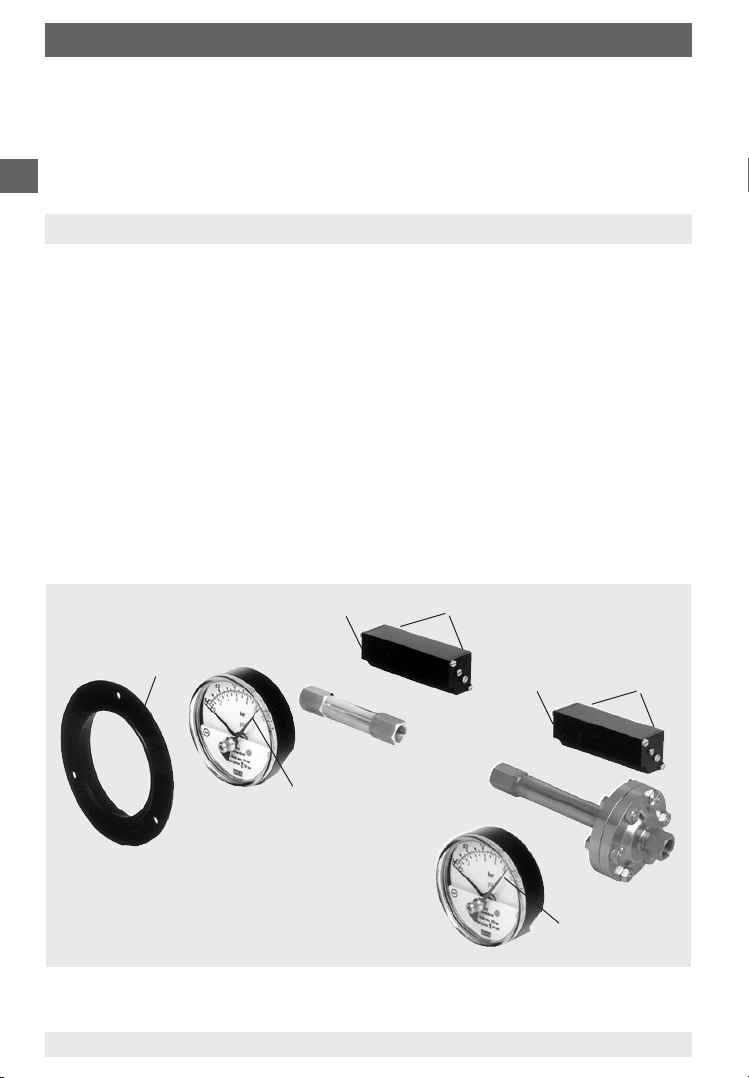
5.1 Mounting ange (only for model 700.01, see left illustration)
May be retrotted on site as required.
Alignment of the front bezel (A) by means of the stamped cams to the grooves
found on the case circumference. Push front bezel on the case until it snaps into
position.
5.2 Minimum or maximum drag pointer (see illustrations)
The drag pointer (B) serves to monitor and control the miniumum or maximum
occurring dierential pressure.
5.3 Reed contact model 851.3 and 851.3.3 (see illustrations)
May be retrotted and adjusted on site as required.
Fastening is by means of two screws (D) integrated in the reed case (C) on the
display case with the pertinent female thread.
C
D
A
C
D
B
B
8
WIKA operating instructions dierential pressure gauge with piston
2103869.04 12/2012 GB/D/F/E
Page 9

6. Transport, packaging and storage / 7. Commissioning ...
6. Transport, packaging and storage
5.1 Transport
Check pressure gauge for any damage that may have been caused by transport.
Obvious damage must be reported immediately.
6.2 Packaging
Do not remove packaging until just before mounting.
Keep the packaging as it will provide optimum protection during transport (e.g.
change in installation site, sending for repair).
6.3 Storage
Permissible conditions at the place of storage:
Storage temperature: -20 ... +70 °C (optional: -40 … +70 °C)
7. Commissioning, operation
Mechanical connection
The installation of the dierential pressure gauge is made following the installation
recommendations for pressure gauges in accordance with EN 837-2 /7.
Mounting of the process connection according to axed symbols ⊕ and ⊖
⊕ high pressure, ⊖ low pressure
GB
■
Hold against the connection pieces in the case of installation by means of
17 mm screw spanner (installation without holding against the connection
pieces may cause thet measuring system to get loose).
■
The maximum permissible medium/ambient temperature must not be
exceeded
■
Prior to the installation of the pressure gauge, clean the measuring lines
thoroughly by tapping and blowing or rinsing
■
Mount and operate the measuring instruments free from vibration
■
Protect measuring instruments from contamination and high temperature
changes
To avoid foreign matter in the measuring system and the resulting damage to the
system, the pressure gauge must be mounted above the connector. For measuring
media containing suspended particles model 700.02 should be used.
2103869.04 12/2012 GB/D/F/E
WIKA operating instructions dierential pressure gauge with piston 9
Page 10
7. Commissioning, operation
If the line to the gauge is not rigid enough for a vibration-free installation, the gauge
should be mounted by means of appropriate fastening elements for wall mounting,
or, if necessary, with a capillary.
GB
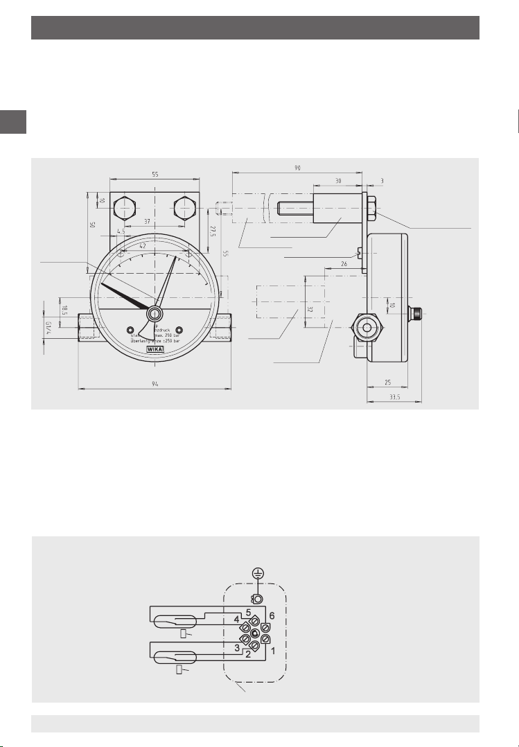
Wall mounting (see drawing)
Installation / fastening by means of mounting brackets
Hexagon bolt
M8 x 50 (M8 x 100)
Drag pointer
Electrical connection
without reed contact
with reed contact
Slotted screw M4 x 10
Plug
Reed case
(for instruments with electrical accessories)
Electrical connection of the pressure gauge is by means of terminal box and
cable. Precise wiring schemes can be seen in the following connection diagram.
In addition both the pin assignment and the required power supply are stated on
the product label of the reed case.
Electrical connection diagram
Reed contact model 851.3 and 851.3.3
(change-over contact)
The instruments do not
provide for incorporated
851.3. 3
2nd contact
overcurrent protectors. If
overcurrent protectors are
requested, these have to
10
851. 3
1nd contact
Terminal box
WIKA operating instructions dierential pressure gauge with piston
be provided for externally.
1581007.02
2103869.04 12/2012 GB/D/F/E
Page 11
7. Commissioning, operation
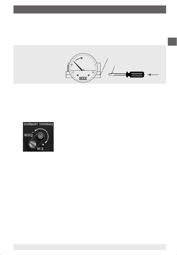
Switch point adjustment
Preference should be given to setting the switch point before installing the
measuring instrument. The necessary test path is generated manually (e.g. by
means of an antimagnetic screwdriver).
Manual test path generation
Plus media chamber
antimagnetic
The switch point can also be set in a pressurised condition after installation. The
switch points are set at the factory when the set points are given.
The switch point is adjusted by turning the contact adjustment screws on the
outside of the reed case.
Anticlockwise rotation:
Switch point can be moved in the direction of the
start of the measuring range
Clockwise rotation:
Switch point can be moved in the direction of the
end of the measuring range
GB
Zero point check
In general, the zero point should only be checked and adjusted at zero pressure.
The system fastening lug on the back of the case can be easily slackened o for
zero point correction of the pressure gauge. Now the zero point can be readjusted
by moving the measuring system to the right or left. After this has been done the
measuring system is to be secured again with the mounting screw (recommended
tightening torque of the mounting screw 1.3 Nm).
2103869.04 12/2012 GB/D/F/E
WIKA operating instructions dierential pressure gauge with piston 11
Page 12
8. Maintenance and cleaning / 9. Dismounting and disposal
8. Maintenance and cleaning
8.1 Maintenance
The instruments are maintenance-free.
GB
The dierential pressure gauges with piston oer long service life provided they
are handled and operated properly.
Checks should be carried out on a regular basis to ensure the measuring
accuracy of the pressure gauge.
Repairs must only be carried out by the manufacturer or appropriately qualied
skilled personnel.
8.2 Cleaning
CAUTION!
■
Clean the pressure gauge with a moist cloth.
■
Wash or clean the dismounted pressure gauge before returning it, in order to protect persons and the environment from
exposure to residual media.
9. Dismounting and disposal
WARNING!
Residual media in dismounted pressure gauges can result in a
risk to persons, the environment and equipment. Take sucient
precautionary measures.
9.1 Dismounting
Only disconnect the pressure gauge once the system has been depressurised!
9.2 Disposal
Incorrect disposal can put the environment at risk.
Dispose of instrument components and packaging materials in an
environmentally compatible way and in accordance with the country-specic
waste disposal regulations.
12
WIKA operating instructions dierential pressure gauge with piston
2103869.04 12/2012 GB/D/F/E
Page 13

Inhalt
Inhalt
1. Allgemeines 14
2. Sicherheit 15
3. Technische Daten 17
4. Aufbau und Funktion 17
5. Optionen und Zubehör 18
6. Transport, Verpackung und Lagerung 19
7. Inbetriebnahme, Betrieb 19
8. Wartung und Reinigung 22
9. Demontage und Entsorgung 22
D
2103869.04 12/2012 GB/D/F/E
13WIKA Betriebsanleitung Kolben-Dierenzdruckmessgerät
Page 14

1. Allgemeines
1. Allgemeines
Das in der Betriebsanleitung beschriebene Dierenzdruckmessgerät wird nach
den neuesten Erkenntnissen konstruiert und gefertigt.
Alle Komponenten unterliegen während der Fertigung strengen Qualitätsund Umweltkriterien. Unsere Managementsysteme sind nach ISO 9001 und
ISO 14001 zertiziert.
D
Diese Betriebsanleitung gibt wichtige Hinweise zum Umgang mit dem
Dierenzdruckmessgerät. Voraussetzung für sicheres Arbeiten ist die Einhaltung
aller angegebenen Sicherheitshinweise und Handlungsanweisungen.
Die für den Einsatzbereich des Dierenzdruckmessgerätes geltenden örtlichen
Unfallverhütungsvorschriften und allgemeinen Sicherheitsbestimmungen
einhalten.
Die Betriebsanleitung ist Produktbestandteil und muss in unmittelbarer Nähe
des Druckmessgerätes für das Fachpersonal jederzeit zugänglich aufbewahrt
werden.
Das Fachpersonal muss die Betriebsanleitung vor Beginn aller Arbeiten sorgfältig
durchgelesen und verstanden haben.
Die Haftung des Herstellers erlischt bei Schäden durch bestimmungswidrige
Verwendung, Nichtbeachten dieser Betriebsanleitung, Einsatz ungenügend
qualizierten Fachpersonals sowie eigenmächtiger Veränderung am
Dierenzdruckmessgerät.
Es gelten die allgemeinen Geschäftsbedingungen in den Verkaufsunterlagen.
Technische Änderungen vorbehalten.
Weitere Informationen:
- Internet-Adresse: www.wika.de / www.wika.com
- zugehöriges Datenblatt: PM 07.14
Symbolerklärung
WARNUNG!
… weist auf eine möglicherweise gefährliche Situation hin, die
zum Tod oder zu schweren Verletzungen führen kann, wenn sie
nicht gemieden wird.
Information
… hebt nützliche Tipps und Empfehlungen sowie Informationen
für einen ezienten und störungsfreien Betrieb hervor.
WIKA Betriebsanleitung Kolben-Dierenzdruckmessgerät14
2103869.04 12/2012 GB/D/F/E
Page 15

2. Sicherheit
2. Sicherheit
WARNUNG!
Vor Montage, Inbetriebnahme und Betrieb sicherstellen, dass
das richtige Druckmessgerät hinsichtlich Messbereich, Ausführung und spezischen Messbedingungen ausgewählt wurde.
Auswahl- und Einbauempfehlungen für Druckmessgeräte nach
EN 837-2 beachten.
Verträglichkeit der druckbelasteten Werkstoe mit dem
Messsto prüfen!
Die Belastungsgrenzen sind einzuhalten, um die Messgenauigkeit und die Lebensdauer zu gewährleisten.
Bei Nichtbeachten können schwere Körperverletzungen und/
oder Sachschäden auftreten.
Weitere wichtige Sicherheitshinweise benden sich in den
einzelnen Kapiteln dieser Betriebsanleitung.
2.1 Bestimmungsgemäße Verwendung
Diese Dierenzdruckmessgeräte dienen zur Überwachung von Dierenzdrücken
bei industriellen Anwendungen.
Das Dierenzdruckmessgerät ist ausschließlich für den hier beschriebenen
bestimmungsgemäßen Verwendungszweck konzipiert und konstruiert und darf
nur dementsprechend verwendet werden.
D
Ansprüche jeglicher Art aufgrund von nicht bestimmungsgemäßer Verwendung
sind ausgeschlossen.
2.2 Personalqualikation
WARNUNG!
Verletzungsgefahr bei unzureichender Qualikation!
Unsachgemäßer Umgang kann zu erheblichen Personen- und
Sachschäden führen.
■
Die in dieser Betriebsanleitung beschriebenen Tätigkeiten nur
durch Fachpersonal nachfolgend beschriebener Qualikation
durchführen lassen.
2103869.04 12/2012 GB/D/F/E
15WIKA Betriebsanleitung Kolben-Dierenzdruckmessgerät
Page 16

2. Sicherheit
Fachpersonal
Das Fachpersonal ist aufgrund seiner fachlichen Ausbildung, seiner Kenntnisse
der Mess- und Regelungstechnik und seiner Erfahrungen sowie Kenntnis der
landesspezischen Vorschriften, geltenden Normen und Richtlinien in der Lage,
die beschriebenen Arbeiten auszuführen und mögliche Gefahren selbstständig
zu erkennen.
D
2.3 Besondere Gefahren
WARNUNG!
Messstoreste in ausgebauten Druckmessgeräten können zur
Gefährdung von Personen, Umwelt und Einrichtung führen.
Ausreichende Vorsichtsmaßnahmen ergreifen.
2.5 Beschilderung / Sicherheitskennzeichnungen
Typenschild (bei Option Reed-Kontakt)
Model 700.02.080 Cont 851.3
MAX. LASTDATEN / CONTACT RATING
Pmax AC/DC 3 W
Umax AC/DC 30 V
Imax AC/DC 0,2 A
E-Nr./Prod-No: 1234567 12/2010
UL-Nr: E103299
CSA-Nr: LR57810
⊖ left
⊕ right
1234567
Symbolerklärung
Vor Montage und Inbetriebnahme des Druckmessgerätes
unbedingt die Betriebsanleitung lesen!
CE, Communauté Européenne
Geräte mit dieser Kennzeichnung stimmen überein mit den
zutreenden europäischen Richtlinien.
Herstellungsdatum
2103869.04 12/2012 GB/D/F/E
WIKA Betriebsanleitung Kolben-Dierenzdruckmessgerät16
Page 17

3. Technische Daten / 4. Aufbau und Funktion
3. Technische Daten
Technische Daten Typ 700.01 Typ 700.02
Nenngröße 80
Anzeigegenauigkeit ± 3 % vom Skalenendwert bei
ansteigendem Dierenzdruck
Anzeigebereiche 0 … 400 mbar bis 0 … 10 bar 0 … 160 mbar bis 0 … 2,5 bar
Max. Betriebsdruck
(statischer Druck)
Überlastbarkeit ein-, beid- und wechselseitig bis zum maximalen Betriebsdruck
Schutzart lP 54 (EN 60529 / lEC 529)
Messkammer mit
Druckanschluss
(messstoberührt)
wahlweise 100, 250 oder
400 bar
(Ausnahme bei Typ 700.02, Anzeigebereiche 0 ... 160 mbar und
0 ... 250 mbar: Überlastbarkeit bis 50 bar)
CrNi-Stahl 1.4571, 2 x G ¼ Innengewinde, rechts und links
seitlich, gegenüberliegend (EN 837-1 /7.3)
± 5 % vom Skalenendwert bei
ansteigendem Dierenzdruck
100 bar
(Anzeigebereiche 0 ... 160 mbar
und 0 ... 250 mbar: 50 bar)
Weitere technische Daten siehe WIKA Datenblatt PM 07.14 und
Bestellunterlagen.
4. Aufbau und Funktion
Beschreibung
In den ⊕- und ⊖- Messstokammern herrschen die Drücke p
durch den druckbeaufschlagten Magnetkolben (bzw. Magnetkolben und
Trennmembrane bei Typ 700.02).
und p2, getrennt
1
D
Die Druckdierenz verursacht eine axiale Bewegung (Messweg) des Kolbens,
der sich gegen die Messbereichsfeder abstützt.
Der sich daraus ergebende Messweg wird von einem auf dem Instrumentenzeiger bendlichen Ringmagneten abgegrien und zur Anzeige gebracht. Dieser
konstruktive Aufbau verbindet den Vorteil einer vollständigen Trennung von
Messsystem und Anzeige und verhindert jegliche Leckage nach außen.
Der Volumenstrom von der ⊕- zur ⊖- Messstokammer bei Typ 700.01 ist
aufgrund des konstruktiven Aufbaus minimal und in Regelanwendungen nicht
störend.
Bewährte Anwendungen/Einsatzgebiete sind Gas- und Luftversorgung und deren
Aufbereitung, in denen keine magnetischen Partikel enthalten sind.
2103869.04 12/2012 GB/D/F/E
17WIKA Betriebsanleitung Kolben-Dierenzdruckmessgerät
Page 18

5. Optionen und Zubehör
Benden sich Schwebekörper im Prozess sollte der Typ 700.02 eingesetzt
werden.
Lieferumfang
Lieferumfang mit dem Lieferschein abgleichen.
D
5. Optionen und Zubehör
5.1 Befestigungsrand (nur bei Typ 700.01, siehe Darstellung links)
Nach Bedarf vor Ort nachrüstbar.
Ausrichten des Frontringes (A) über eingeprägte Nocken zu am Gehäuseumfang
bendlichen Nuten. Frontring auf Gehäuse bis zum Einschnappen aufschieben.
5.2 Minimum- bzw. Maximum-Schleppzeiger (siehe Darstellungen)
Schleppzeiger (B) dient zur Überwachung und Kontrolle des minimalen bzw.
maximalen aufgetretenen Dierenzdruckes.
5.3 Reed-Kontakt Typ 851.3 und 851.3.3 (siehe Darstellungen)
Nach Bedarf vor Ort nachrüst- und einstellbar.
Befestigung erfolgt über zwei im Reedgehäuse (C) integrierte Schrauben (D) am
Anzeigegehäuse mit dem dazugehörigen Innengewinde.
C
D
A
C
D
B
B
WIKA Betriebsanleitung Kolben-Dierenzdruckmessgerät18
2103869.04 12/2012 GB/D/F/E
Page 19

6. Transport, Verpackung und Lagerung / 7. Inbetriebnahme ...
6. Transport, Verpackung und Lagerung
5.1 Transport
Druckmessgerät auf eventuell vorhandene Transportschäden untersuchen.
Oensichtliche Schäden unverzüglich mitteilen.
6.2 Verpackung
Verpackung erst unmittelbar vor der Montage entfernen.
Die Verpackung aufbewahren, denn diese bietet bei einem Transport einen
optimalen Schutz (z. B. wechselnder Einbauort, Reparatursendung).
6.3 Lagerung
Zulässige Bedingungen am Lagerort
Lagertemperatur: -20 ... +70 °C (optional: -40 … +70 °C)
7. Inbetriebnahme, Betrieb
Mechanischer Anschluss
Die Montage des Dierenzdruckmessgerätes erfolgt in Anlehnung an die Einbauempfehlungen für Druckmessgeräte nach EN 837-2 /7.
Montage des Prozessanschlusses nach angebrachten Symbolen ⊕ und ⊖
⊕ hoher Druck, ⊖ niedriger Druck
D
■
Bei Montage mittels Schraubenschlüssel SW 17 an den Anschlussstücken
gegenhalten (Einschrauben ohne gegenhalten kann zur Lockerung des
Messsystems führen).
■
Maximale zulässige Messsto-/Umgebungstemperatur darf nicht überschritten
werden
■
Messleitungen vor der Gerätemontage gründlich durch Abklopfen und
Ausblasen oder Durchspülen reinigen
■
Messgeräte sollen erschütterungsfrei montiert und betrieben werden
■
Messgeräte sollen vor Verschmutzung und starken Temperaturschwankungen
geschützt sein
Um Fremdkörper im Messsystem und somit eine Beschädigung desselben zu
vermeiden, ist das Druckmessgerät oberhalb des Entnahmestutzens anzubringen.
Für schwebekörperhaltige Messstoe ist der Typ 700.02 vorzusehen.
2103869.04 12/2012 GB/D/F/E
19WIKA Betriebsanleitung Kolben-Dierenzdruckmessgerät
Page 20

7. Inbetriebnahme, Betrieb
Ist die Leitung zum Druckmessgerät für eine erschütterungsfreie Anbringung nicht
stabil genug, so ist die Befestigung über entsprechende Befestigungselemente für
Wandmontage oder ggf. über eine Kapillare vorzunehmen.
Montage an Wand (siehe Zeichnung)
Anbringung/Befestigung mittels Messgerätehalter
D
Sechskantschraube
M8 x 50 (M8 x 100)
Schleppzeiger
Elektrischer Anschluss
ohne Reedkontakt
mit Reedkontakt
Schlitzschraube M4 x 10
Stecker
Reedgehäuse
(bei Geräten mit elektrischen Zusatzeinrichtungen)
Der elektrische Anschluss des Druckmessgerätes wird über Kabeldose und Kabel
hergestellt. Die genauen Anschlussbelegungen können dem nachfolgenden
Anschlussschema entnommen werden. Zusätzlich sind Anschlussbelegung und
erforderliche Hilfsenergie auf dem Typenschild des Reedgehäuses vermerkt.
Elektrisches Anschlussschema
Reed-Kontakt Typ 851.3 und 851.3.3
(Wechsler)
In den Geräten sind
keine Überstrom-Schutz-
851.3. 3
2. Kontakt
einrichtungen eingebaut.
Falls Schutzeinrichtungen
gefordert werden, sind
851. 3
1. Kontakt
Kabeldose
WIKA Betriebsanleitung Kolben-Dierenzdruckmessgerät20
diese extern vorzusehen.
1581007.02
2103869.04 12/2012 GB/D/F/E
Page 21

7. Inbetriebnahme, Betrieb
Schaltpunkteinstellung
Vorzugsweise erfolgt die Schaltpunkteinstellung vor dem Einbau des
Messgerätes. Der erforderliche Prüfweg wird manuell (z. B. mit Hilfe eines
nicht magnetischen Schraubendrehers) erzeugt.
Manuelle Prüfwegerzeugung
Plusmessstokammer
antimagnetisch
Die Schaltpunkteinstellung kann auch im druckbeaufschlagten Zustand nach
Einbau erfolgen. Bei Angabe der Sollwerte werden werkseitig die Schaltpunkte
eingestellt.
Die Verstellung des Schaltpunktes erfolgt durch Drehen der Kontakt-Einstellschrauben an der Reed-Gehäuseaußenseite.
Drehrichtung links:
Schaltpunkt lässt sich in Richtung
Messbereichsanfang verschieben
Drehrichtung rechts:
Schaltpunkt lässt sich in Richtung
Messbereichs
ende verschieben
D
Nullpunktprüfung
Im Allgemeinen erfolgt die Überprüfung und Einstellung des Nullpunktes im
drucklosen Zustand. Für die Nullpunktkorrektur des Druckmessgerätes ist
die Systembefestigungslasche an der Gehäuserückseite leicht zu lösen. Der
Nullpunkt lässt sich nun durch Verschieben des Messsystems nach rechts
oder links nachjustieren. Anschließend ist das Messsystem wieder mit der
Befestigungsschraube (empfohlenes Anzugsmoment der Befestigungsschraube
1,3 Nm) zu xieren.
2103869.04 12/2012 GB/D/F/E
21WIKA Betriebsanleitung Kolben-Dierenzdruckmessgerät
Page 22

8. Wartung und Reinigung / 9. Demontage und Entsorgung
8. Wartung und Reinigung
8.1 Wartung
Die Geräte sind wartungsfrei.
Bei sachgemäßer Behandlung und Bedienung zeichnen sich die Kolben-Die-
renzdruckmessgeräte durch eine hohe Lebensdauer aus.
D
Die Messgenauigkeit des Druckmessgerätes sollte durch regelmäßige Prüfungen
sichergestellt werden.
Reparaturen sind ausschließlich vom Hersteller oder entsprechend qualiziertem
Fachpersonal durchzuführen.
8.2 Reinigung
VORSICHT!
■
Das Druckmessgerät mit einem feuchten Tuch reinigen.
■
Ausgebautes Druckmessgerät vor der Rücksendung spülen
bzw. säubern, um Personen und Umwelt vor Gefährdung durch
anhaftende Messstoreste zu schützen.
9. Demontage und Entsorgung
WARNUNG!
Messstoreste in ausgebauten Druckmessgeräten können
zur Gefährdung von Personen, Umwelt und Einrichtung führen.
Ausreichende Vorsichtsmaßnahmen ergreifen.
9.1 Demontage
Druckmessgerät nur im drucklosen Zustand demontieren!
9.2 Entsorgung
Durch falsche Entsorgung können Gefahren für die Umwelt entstehen.
Gerätekomponenten und Verpackungsmaterialien entsprechend den landesspezischen Abfallbehandlungs- und Entsorgungsvorschriften umweltgerecht
entsorgen.
WIKA Betriebsanleitung Kolben-Dierenzdruckmessgerät22
2103869.04 12/2012 GB/D/F/E
Page 23

Sommaire
Sommaire
1. Généralités 24
2. Sécurité 25
3. Caractéristiques techniques 27
4. Conception et fonction 27
5. Options et accessoires 28
6. Transport, emballage et stockage 29
7. Mise en service, exploitation 29
8. Entretien et nettoyage 32
9. Démontage et mise au rebut 32
F
2103869.04 12/2012 GB/D/F/E
WIKA mode d'emploi manomètre pour pression diérentielle avec piston 23
Page 24

1. Généralités
1. Généralités
Le manomètre de pression diérentielle décrit dans le mode d'emploi est conçu
et fabriqué selon les dernières technologies en vigueur. Tous les composants
sont soumis à des critères de qualité et d'environnement stricts durant la
fabrication. Nos systèmes de gestion sont certiés selon ISO 9001 et ISO 14001.
Ce mode d'emploi donne des indications importantes concernant l'utilisation du
manomètre de pression diérentielle. Il est possible de travailler en toute sécurité
avec ce produit en respectant toutes les consignes de sécurité et d'utilisation.
F
Respecter les prescriptions locales de prévention contre les accidents et les
prescriptions générales de sécurité en vigueur pour le domaine d‘application du
manomètre de pression diérentielle.
Le mode d'emploi fait partie de l'appareil et doit être conservé à proximité
immédiate du manomètre et accessible à tout moment pour le personnel qualié.
Le personnel qualié doit, avant de commencer toute opération, avoir lu
soigneusement et compris le mode d'emploi.
La responsabilité du fabricant n'est pas engagée en cas de dommages
provoqués par une utilisation non conforme à l'usage prévu, de non respect de
ce mode d'emploi, d'utilisation de personnel peu qualié de même qu'en cas de
modications du manomètre de pression diérentielle eectuées par l'utilisateur.
Les conditions générales de vente mentionnées dans les documents de vente
s'appliquent.
Sous réserve de modications techniques.
Pour obtenir d'autres informations :
- Consulter notre site internet : www.wika.fr
- Fiche technique correspondante : PM 07.14
Explication des symboles
AVERTISSEMENT !
… indique une situation présentant des risques susceptibles
de provoquer la mort ou des blessures graves si elle n'est pas
évitée.
Information
… met en exergue les conseils et recommandations utiles de
même que les informations permettant d'assurer un fonctionnement ecace et normal.
WIKA mode d'emploi manomètre pour pression diérentielle avec piston24
2103869.04 12/2012 GB/D/F/E
Page 25

2. Sécurité
2. Sécurité
AVERTISSEMENT !
Avant le montage, la mise en service et le fonctionnement,
s'assurer que le manomètre a été choisi de façon adéquate, en
ce qui concerne la plage de mesure, la version et les conditions
de mesure spéciques.
Respecter les recommandations de sélection et d'installation
pour les manomètres conformément à la norme EN 837-2.
Vérier si les matériaux soumis à la pression sont compatibles
avec le uide de mesure !
Les limites de surpression admissible sont à respecter an
d'assurer la précision et la durée de vie.
Un non-respect de cette consigne peut entraîner des blessures
corporelles graves et/ou des dégâts matériels.
Vous trouverez d'autres consignes de sécurité dans les sections
individuelles du présent mode d'emploi.
2.1 Utilisation conforme à l'emploi prévu
Les manomètres diérentiels sont utilisés pour visualiser les pressions diérentielles dans des applications industrielles.
F
Le manomètre de pression diérentielle est conçu et construit exclusivement
pour une utilisation conforme à l'usage prévu décrit ici et ne doit être utilisé qu'en
conséquence.
Aucune réclamation ne peut être recevable en cas d'utilisation non conforme à
l'usage prévu.
2.2 Qualication du personnel
AVERTISSEMENT !
Danger de blessure en cas de qualication insusante !
Une utilisation non conforme peut entraîner d'importants
dommages corporels et matériels.
■
Les opérations décrites dans ce mode d'emploi ne doivent
être eectuées que par un personnel ayant la qualication
décrite ci-après.
2103869.04 12/2012 GB/D/F/E
WIKA mode d'emploi manomètre pour pression diérentielle avec piston 25
Page 26

2. Sécurité
Personnel qualié
Le personnel qualié est, en raison de sa formation spécialisée, de ses connaissances dans le domaine de la technique de mesure et de régulation et de ses
expériences de même que de sa connaissance des prescriptions nationales des
normes et directives en vigueur, en mesure d'eectuer les travaux décrits et de
reconnaître automatiquement les dangers potentiels.
2.3 Dangers particuliers
F
AVERTISSEMENT !
Les substances résiduelles dans les manomètres démontés
peuvent occasionner un risque pour les personnes,
l'environnement et l'équipement. Prendre des mesures de
sécurité susantes.
2.5 Etiquetage / Marquages de sécurité
Plaque signalétique (avec l'option contact reed)
Model 700.02.080 Cont 851.3
MAX. LASTDATEN / CONTACT RATING
Pmax AC/DC 3 W
Umax AC/DC 30 V
Imax AC/DC 0.2 A
E-Nr./Prod-No: 1234567 12/2010
Explication des symboles
Avant de monter et mettre le manomètre en service, lire impérativement le mode d'emploi !
CE, Communauté Européenne
Les appareils avec ce marquage sont conformes aux directives
européennes pertinentes.
UL-Nr: E103299
CSA-Nr: LR57810
⊖ left
⊕ right
1234567
Date de fabrication
WIKA mode d'emploi manomètre pour pression diérentielle avec piston26
2103869.04 12/2012 GB/D/F/E
Page 27

3. Caractéristiques techniques / 4. Conception et fonction
3. Caractéristiques techniques
Caractéristiques
techniques
Diamètre 80
Classe de précision ± 3 % de la valeur de pleine
Echelles de mesure 0 … 400 mbar à 0 … 10 bar 0 … 160 mbar à 0 … 2,5 bar
Pression de service
max.
(pression statique)
Sécurité contre la
surpression
Indice de protection lP 54 (EN 60529 / lEC 529)
Chambre de mesure
avec raccord de
pression (en contact)
Type 700.01 Type 700.02
± 5 % de la valeur de pleine
échelle avec augmentation de
la pression diérentielle
en option, 100, 250 ou 400 bar 100 bar (échelles de mesure
de chaque côté de la pression de service maximale (exception pour le type 700.02, échelles de mesure 0 ... 160 mbar et
0 ... 250 mbar : sécurité contre la surpression jusqu'à 50 bar)
Acier inoxydable 1.4571, 2 x letage G ¼ femelle, côtés droit et
gauche, en ligne (EN 837-1 /7.3)
échelle avec augmentation de
la pression diérentielle
0 ... 160 mbar et 0 ... 250 mbar:
50 bar)
Pour de plus amples spécications, voir la che technique WIKA PM 07.14 et la
documentation de commande.
4. Conception et fonction
Description
Dans les chambres de mesure de uide ⊕ et ⊖ il y a les pressions p
séparées par le piston magnétique sous charge (ou piston magnétique et
membrane de séparation pour le type 700.02).
et p2,
1
F
La diérence de pression provoque un déplacement axial (chemin de mesure) du
piston s‘appuyant contre le ressort de l‘étendue de mesure.
Le chemin de mesure en résultant est prélevé par un aimant torique se trouvant
sur l‘aiguille de l‘instrument et est ainsi aché. Ce montage associe l‘avantage
d‘une séparation intégrale entre le système de mesure et l‘achage et empêche
toute fuite à l‘extérieur.
Le débit du volume de la chambre de mesure ⊕ à la chambre⊖ est, pour le type
700.01 en raison de sa construction minime et non gênant en utilisation normale.
Des utilisations/domaines d‘applications éprouvées sont les alimentations en gaz
et en air ne contenant aucune particule magnétique.
2103869.04 12/2012 GB/D/F/E
WIKA mode d'emploi manomètre pour pression diérentielle avec piston 27
Page 28

5. Options et accessoires
Il faut utiliser le type 700.02 si des matières en suspension se trouvent dans le
processus.
Détail de la livraison
Comparer le détail de la livraison avec le bordereau de livraison.
5. Options et accessoires
5.1 Bride de montage (uniquement pour le type 700.01, voir illustration de
F
gauche)
Peut être réajustée sur site le cas échéant.
Aligner les ergots empreints de la collerette (A) aux rainures sur la circonférence
du boîtier. Enfoncer la collerette jusqu‘à l‘encliquetage.
5.2 Aiguille suiveuse minimum ou maximum (voir illustrations)
L'aiguille suiveuse (B) permet une visualisation et un contrôle de la pression
diérentielle minimale ou maximale présente.
5.3 Contact reed type 851.3 et 851.3.3 (voir illustrations)
Peuvent être réajustés sur site le cas échéant.
À l'aide de deux vis (D) intégrées dans le boîtier du reed (C), la xation s'eectue
sur le boîtier d'achage via les taraudages correspondants.
C
D
A
C
D
B
B
WIKA mode d'emploi manomètre pour pression diérentielle avec piston28
2103869.04 12/2012 GB/D/F/E
Page 29

6. Transport, emballage et stockage / 7. Mise en service ...
6. Transport, emballage et stockage
5.1 Transport
Vérier s'il existe des dégâts sur le manomètre liés au transport. Communiquer
immédiatement les dégâts constatés.
6.2 Emballage
N'enlever l'emballage qu'avant le montage.
Conserver l'emballage, celui-ci ore, lors d'un transport, une protection optimale
(par ex. changement de lieu d'utilisation, renvoi pour réparation).
6.3 Stockage
Conditions admissibles sur le lieu de stockage :
Température de stockage : -20 ... +70 °C (en option : -40 … +70 °C)
7. Mise en service, exploitation
Raccordement mécanique
L'installation du manomètre de pression diérentielle s'eectue d'après les
recommandations d'installation pour les manomètres conformément à la norme
EN 837-2 /7.
Monter le raccordement process conformément aux symboles apposés ⊕ et ⊖
⊕ haute pression, ⊖ basse pression
F
■
Lors du montage maintenir les raccords sur l‘appareil au moyen d‘une
clé à fourche de 17 (un vissage sans cette précaution peut conduire à un
desserrement du système de mesure).
■
La température admissible pour le uide/l‘ambiance ne doit pas être dépassée
■
Avant d'installer le manomètre, nettoyer les conduites de mesure en tapant et
en souant ou en rinçant
■
Monter et utiliser les instruments de mesure de manière à ce qu'ils ne soient
pas soumis à des vibrations
■
Protégez les instruments de mesure contre la contamination et les variations
de température élevées
An d'éviter toute pénétration de corps étrangers dans le système de mesure
et tout dommage qui peut en résulter pour le système, monter le manomètre
au-dessus du raccord. Pour la mesure de uide contenant des particules en
suspension, utiliser le type 700.02.
2103869.04 12/2012 GB/D/F/E
WIKA mode d'emploi manomètre pour pression diérentielle avec piston 29
Page 30

7. Mise en service, exploitation
Au cas où le tuyau raccordant le manomètre ne serait pas susamment stable
pour une xation exempte de vibrations, il faut eectuer la xation à l‘aide
d‘éléments pour installation sur paroi ou, le cas échéant, par l‘intermédiaire d‘un
tube capillaire.
Montage sur paroi (voir dessin)
Installation / xation à l'aide d'étriers
F
sans contact de reed
avec contact de reed
Aiguille suiveuse
Vis à tête fendue M4 x 10
Connecteur
Boîtier de reed
Boulon hexagonal
M8 x 50 (M8 x 100)
1581007,02
Raccords électriques (pour des instruments avec accessoires électrique)
Le raccord électrique du manomètre est eectué par une boîte de jonction et des
câbles. Le groupement exact des raccords est montré dans le schéma de branchement suivant. En outre, le groupement des raccords et l’énergie auxiliaire sont
marqués sur la plaque signalétique du boîtier de reed.
Schéma de raccordement électrique
Contact reed type 851.3 et 851.3.3
(contact inverseur)
Aucun dispositif de
protection de surtension
851,3. 3
2ème contact
n‘est installé dans les
instruments. Au cas où
des dispositifs de protec-
851. 3
1er contact
Boîte de jonction
WIKA mode d'emploi manomètre pour pression diérentielle avec piston30
tion sont exigés, ceux-ci
sont à prévoir à l‘extérieur.
2103869.04 12/2012 GB/D/F/E
Page 31

7. Mise en service, exploitation
Réglage du point de commutation
De préférence, le réglage du point de commutation doit se faire avant le montage
de l‘instrument. Le contrôle du déplacement se fait manuellement (par exemple à
l‘aide d‘un tournevis non magnétique).
Réalisation du contrôle de déplacement manuel
Chambre du uide positive
antimagnétique
Le réglage du point de commutation peut aussi être fait sous pression, après le
montage. Sous indication des valeurs de consigne, les points de commutation
sont réglés en usine.
Le réglage se fait en tournant les vis de réglage de commutation du contact à
l‘extérieur du boîtier de reed.
Rotation antihoraire :
Le point de commutation peut être déplacé en
direction du début de l‘étendue de mesure
Rotation horaire :
Le point de commutation se déplace en direction
de la n de l‘étendue de mesure
F
Contrôle du zéro
En général, le contrôle et le réglage du zéro se font sans pression. Pour corriger
le zéro, il faut légèrement dévisser l’éclisse de xation du système à l’arrière du
boîtier. Maintenant le zéro peut être corrigé en déplaçant le système de mesure à
gauche ou à droite. Ensuite le système de mesure doit être xé de nouveau avec la
vis de xation (couple de serrage recommandé de la vis de xation 1,3 Nm).
2103869.04 12/2012 GB/D/F/E
WIKA mode d'emploi manomètre pour pression diérentielle avec piston 31
Page 32

8. Entretien et nettoyage / Démontage et mise au rebut
8. Entretien et nettoyage
8.1 Entretien
Les instruments ne requièrent aucun entretien.
S‘ils sont manipulés et utilisés correctement, les instruments ne requièrent
aucune maintenance et se distinguent par une longue durée de vie.
Procéder aux contrôles à intervalles réguliers de manière à garantir la précision
de mesure du manomètre.
F
Les réparations doivent être eectuées exclusivement par le fabricant ou par un
personnel qualié.
8.2 Nettoyage
ATTENTION !
■
Nettoyer le manomètre avec un chion humide.
■
Laver ou nettoyer le manomètre démonté avant de le retourner
an de protéger les collaborateurs et l‘environnement contre le
danger lié aux restes de uides adhérents.
9. Démontage et mise au rebut
AVERTISSEMENT !
Les restes de uides se trouvant dans des manomètres démontés peuvent mettre en danger les personnes,
l'environnement ainsi que l'installation. Prendre des mesures de
sécurité susantes.
9.1 Démontage
Déconnecter le manomètre uniquement une fois que le système a été mis hors
pression.
9.2 Mise au rebut
Une mise au rebut inadéquate peut entraîner des dangers pour l'environnement.
Éliminer les composants des appareils et les matériaux d'emballage
conformément aux prescriptions nationales pour le traitement et l'élimination des
déchets et aux lois de protection de l'environnement en vigueur.
WIKA mode d'emploi manomètre pour pression diérentielle avec piston32
2103869.04 12/2012 GB/D/F/E
Page 33

Contenido
Contenido
1. Información general 34
2. Seguridad 35
3. Datos técnicos 37
4. Diseño y función 37
5. Opciones y accesorios 38
6. Transporte, embalaje y almacenamiento 39
7. Puesta en servicio, funcionamiento 39
8. Mantenimiento y limpieza 42
9. Desmontaje y eliminación 42
E
2103869.04 12/2012 GB/D/F/E
WIKA manual de instrucciones manómetro diferencial con pistón 33
Page 34

1. Información general
1. Información general
El manómetro diferencial descrito en el manual de instrucciones está construido
y fabricado según los conocimientos actuales. Todos los componentes están
sujetos a criterios rígidos de calidad y medio ambiente durante la producción.
Nuestros sistemas de gestión están certicados según ISO 9001 e ISO 14001.
Este manual de instrucciones proporciona indicaciones importantes acerca del
manejo del manómetro diferencial. Para un trabajo seguro es imprescindible
cumplir con todas las instrucciones de seguridad y manejo indicadas.
Cumplir normativas sobre la prevención de accidentes y las normas de seguridad
en vigor en el lugar de utilización del manómetro diferencial.
El manual de instrucciones es una parte integrante del manómetro y debe
guardarse en la proximidad del mismo para que el personal especializado pueda
E
consultarlo en cualquier momento.
El personal especializado debe haber leído y entendido el manual de
instrucciones antes de comenzar cualquier trabajo.
El fabricante queda exento de cualquier responsabilidad en caso de daños
causados por un uso no conforme a la nalidad prevista, la inobservancia del
presente manual de instrucciones, un manejo por personal insucientemente
cualicado así como una modicación no autorizada del manómetro diferencial.
Se aplican las condiciones generales de venta incluidas en la documentación de
venta.
Modicaciones técnicas reservadas.
Para obtener más informaciones consultar:
- Página web: www.wika.es
- Hoja técnica correspondiente: PM 07.14
Explicación de símbolos
¡ADVERTENCIA!
… indica una situación probablemente peligrosa que pueda
causar la muerte o lesiones graves si no se evita.
Información
... marca consejos y recomendaciones útiles así como
informaciones para una utilización ecaz y libre de fallos.
WIKA manual de instrucciones manómetro diferencial con pistón34
2103869.04 12/2012 GB/D/F/E
Page 35

2. Seguridad
2. Seguridad
¡ADVERTENCIA!
Antes del montaje, la puesta en servicio y el funcionamiento
asegurarse de que se haya seleccionado el manómetro
adecuado con respecto a rango de medida, versión y
condiciones de medición especícas.
Observar las recomendaciones relativas a la selección y al
montaje para manómetros según EN 837-2.
¡Asegúrese de que los productos bajo presión sean aptos para
el material de medición!
Para garantizar la precisión de medición y la durabilidad del
instrumento, se deberán respetar los límites de carga.
El no respetar las instrucciones puede generar lesiones graves
y/o daños materiales.
Los capítulos de este manual de instrucciones contienen otras
importantes indicaciones de seguridad.
2.1 Uso conforme a lo previsto
Los manómetros diferenciales sirven para monitorizar las presiones diferenciales
en aplicaciones industriales.
E
El manómetro diferencial ha sido diseñado y construido únicamente para la
nalidad aquí descrita y debe utilizarse en conformidad a la misma.
No se admite ninguna reclamación debido a una utilización no conforme a lo
previsto.
2.2 Cualicación del personal
¡ADVERTENCIA!
¡Riesgo de lesiones debido a una insuciente
cualicación!
Un manejo no adecuado puede causar considerables daños
personales y materiales.
■
Las actividades descritas en este manual de instrucciones
deben realizarse únicamente por personal especializado con
la consiguiente cualicación.
2103869.04 12/2012 GB/D/F/E
WIKA manual de instrucciones manómetro diferencial con pistón 35
Page 36

2. Seguridad
Personal especializado
Debido a su formación profesional, a sus conocimientos de la técnica de regulación y medición así como a su experiencia y su conocimiento de las normativas,
normas y directivas vigentes en el país de utilización el personal especializado es
capaz de ejecutar los trabajos descritos y reconocer posibles peligros por sí solo.
2.3 Riesgos especícos
¡ADVERTENCIA!
Restos de medios en manómetros desmontados pueden crear
riesgos para personas, medio ambiente e instalación. Tomar
adecuadas medidas de precaución.
2.5 Rótulos / Marcados de seguridad
E
Placa indicadora (con opción contacto Reed)
Model 700.02.080 Cont 851.3
MAX. LASTDATEN / CONTACT RATING
Pmax AC/DC 3 W
Umax AC/DC 30 V
Imax AC/DC 0,2 A
E-Nr./Prod-No: 1234567 12/2010
UL-Nr: E103299
CSA-Nr: LR57810
⊖ left
⊕ right
1234567
Explicación de símbolos
¡Es absolutamente necesario leer el manual de instrucciones
antes del montaje y la puesta en servicio del manómetro!
CE, Communauté Européenne
Los instrumentos con este marcaje cumplen las directivas
europeas aplicables.
WIKA manual de instrucciones manómetro diferencial con pistón36
Fecha de fabricación
2103869.04 12/2012 GB/D/F/E
Page 37

3. Datos técnicos / 4. Diseño y función
3. Datos técnicos
Datos técnicos Modelo 700.01 Modelo 700.02
Diámetro nominal 80
Precisión de
indicación
Rangos de indicación 0 … 400 mbar a 0 … 10 bar 0 … 160 mbar a 0 … 2,5 bar
Presión de trabajo
máx.
(presión estática)
Protección contra la
sobrepresión
Tipo de protección lP 54 (EN 60529 / lEC 529)
Cámara de medición
con conexión (en
contacto con el medio)
± 3 % del valor de escala con
presión diferencial subiendo
seleccionable 100, 250 ó
400 bar
un lado dos lados y alternantes hasta la presión de servicio máx.
(excepto modelo 700.02, rango de indicación 0 ... 160 mbar y
0 ... 250 mbar: resistencia contra sobrecarga hasta 50 bar)
Acero CrNi 1.4571, 2 x G ¼ rosca hembra, derecha e izquierda
lateral, en lado opuesto (EN 837-1 /7.3)
± 5 % del calor de escala con
presión diferencial subiendo
100 bar (Rangos de indicación
0 ... 160 mbar y 0 ... 250 mbar:
50 bar)
Para más datos técnicos véase la hoja técnica de WIKA PM 07.14 y la
documentación de pedido.
4. Diseño y función
E
Descripción
Las cámaras de medio de medida ⊕ y ⊖ tienen las presiones p
y p2, separa-
1
dos por el pistón magnético, sometido a presión o pistón y membrana en el
modelo 700.02.
Diferencia de presión, provocada por un movimiento axial (trayecto de medida)
del pistón apoyado al muelle del rango de medida.
El imán circular en la aguja toma el trayecto de medida resultante y lo visualiza.
Ese diseño combina las ventajas de la separación total del sistema de medición
y de la indicación e impide el escape hacia fuera.
El caudal que se produce desde la cámara ⊕ hacia ⊖ es mímimo en el modelo
700.01 debido a su forma constructiva y no perturba las aplicaciones habituales.
Los campos de aplicación típicos son la alimentación de gas y aire y la preparación de los mismos sin partículas magnéticas.
2103869.04 12/2012 GB/D/F/E
WIKA manual de instrucciones manómetro diferencial con pistón 37
Page 38

5. Opciones y accesorios
Utilizar el modelo 700.02 si hay partículas en suspensión en el proceso.
Volumen de suministro
Comprobar mediante el albarán si se ha entregado la totalidad de las piezas.
5. Opciones y accesorios
5.1 Borde (sólo con modelo 700.01, véase la ilustración a la izquierda)
Puede reequiparse in situ.
Alinear el anillo frontal (A) insertando los salientes en las ranuras de la caja.
Empujar el anillo frontal hasta que enganche en la caja.
5.2 Indicador de seguimiento para MÍN y MÁX (véase las ilustraciones)
E
El indicador de seguimiento (B) sirve para monitorizar y controlar la presión
diferencial mínima y máxima.
5.3 Contacto Reed modelos 851.3 y 851.3.3 (véase las ilustraciones)
Puede reequiparse y ajustarse in situ.
Los contactos se jan a través de dos tornillos (D) integrados en la caja Reed (C)
a la caja del indicador con las roscas hembra correspondientes.
C
D
A
C
D
B
B
WIKA manual de instrucciones manómetro diferencial con pistón38
2103869.04 12/2012 GB/D/F/E
Page 39

6. Transporte, embalaje y almacenamiento / 7. Puesta en servicio ...
6. Transporte, embalaje y almacenamiento
5.1 Transporte
Comprobar si el manómetro presenta eventuales daños causados en el
transporte. Noticar daños obvios de forma inmediata.
6.2 Embalaje
No quitar el embalaje hasta justo antes del montaje.
Guardar el embalaje porque es la protección ideal durante el transporte (por
ejemplo si el lugar de instalación cambia o si se envía el instrumento para
posibles reparaciones).
6.3 Almacenamiento
Condiciones admisibles en el lugar de almacenamiento
Temperatura de almacenamiento: -20 ... +70 °C (opcional: -40 … +70 °C)
7. Puesta en servicio, funcionamiento
La conexión mecánica
El manómetro diferencial se instala según las recomendaciones relativas al
montaje para manómetros según EN 837-2 /7.
Montaje de la conexión a proceso según símbolos indicados, ⊕ y ⊖
⊕ presión alta, ⊖ presión baja
E
■
Para el montaje utilizar una llave (ancho de llave 17) para retener los
conectores (si se atornillan sin mantener los conectores puede ser que se
suelte el sistema de medición).
■
No debe excederse la temperatura de la sustancia a medir/ambiente máx.
admisible
■
Antes de montar el instrumento, sacudir o limpiar con aire comprimido o agua
las líneas de medición
■
Los dispositivos de medición deben montarse y operarse de modo libre de
vibraciones.
■
Proteger los dispositivos de medición contra la obturación, las grandes
oscilaciones de temperatura y las vibraciones
El manómetro debe montarse por encima del racor de toma para evitar que
cuerpos ajenos entren en el sistema de medición y dañen el instrumento. Para los
medios con partículas en suspensión se debe utilizar el modelo 700.02.
2103869.04 12/2012 GB/D/F/E
WIKA manual de instrucciones manómetro diferencial con pistón 39
Page 40

7. Puesta en servicio, funcionamiento
Si el soporte conductor hacia el manómetro no es sucientemente estable para
proteger contra sacudidas, hay que jar el manómetro mediante elementos de
jación adecuados para el montaje en la pared, si fuera necesario, a través de un
capilar.
Montaje en la pared (véase el dibujo)
Montaje/jación mediante soporte de instrumento
Sin contacto Reed
Con contacto Reed
Aguja de arrastre
E
Tornillo de cabeza ranurada
M4 x 10
Clavija
Caja Reed
Tornillo de cabeza
hexagonal
M8 x 50 (M8 x 100)
1581007.02
Conexión eléctrica
(para instrumentos con dispositivos eléctricos adicionales)
La conexión eléctrica del manómetro se realiza a través de una caja de cables y
un cable. Los detalles del conexionado pueden verse en el esquema de conexión
siguiente. Los detalles del conexionado y la alimentación auxiliar necesaria se
encuentran también en la placa indicadora de la caja Reed.
Esquema de conexión eléctrica
Contacto Reed modelo 851.3 y 851.3.3
(inversor)
Los instrumentos no
incluyen dispositivos de
851.3. 3
2o contacto
seguridad contra sobrecorriente. Si se necesitan
dispositivos de seguridad
WIKA manual de instrucciones manómetro diferencial con pistón40
851. 3
1º contacto
Caja de cables
hay que utilizar dispositivos exteriores.
2103869.04 12/2012 GB/D/F/E
Page 41

7. Puesta en servicio, funcionamiento
Ajuste del punto de interrupción
El punto de interrupción se ajusta preferentemente antes de instalar el dispositivo
de medición. El trayecto de prueba necesario se genera manualmente (p. ej. con
un destornillador antimagnético).
Generación manual del trayecto de prueba
Cámara de sustancia a medir positiva
Antimagnético
El punto de interrupción puede ajustarse también después del montaje en estado
a presión. Los puntos de interrupción pueden ajustarse en fábrica si se indican
los valores nominales.
El punto de interrupción puede cambiarse girando los tornillos de ajuste del
contacto en el exterior de la caja Reed.
Rotación hacia la izquierda:
El punto de interrupción se desplaza en dirección
del inicio del rango de medida
Rotación hacia la derecha:
El punto de interrupción se desplaza en dirección
del
nal del rango de medida
Control del punto cero
El control y ajuste del punto cero deberá efectuarse sin someter el instrumento
a presión. Para ajustar el punto cero del manómetro hay que soltar la oreja de
jación del sistema en el lado posterior de la caja. El punto cero puede ajustarse
deplazando el sistema de medición hacia la derecha o la izquierda. Fijar otra vez
el sistema de medición con el tornillo de jación (par de apriete recomendado del
tornillo de jación 1,3 Nm).
E
2103869.04 12/2012 GB/D/F/E
WIKA manual de instrucciones manómetro diferencial con pistón 41
Page 42

8. Mantenimiento y limpieza / 9. Desmontaje y eliminación
8. Mantenimiento y limpieza
8.1 Mantenimiento
Los instrumentos no requieren mantenimiento.
Los manómetros diferenciales con pistón no necesitan mantenimiento y
se distinguen por su prolongada vida útil si se manejan y operan de forma
apropiada.
Mediante comprobaciones periódicas se debe asegurar la precisión de medición
de los manómetros.
Todas las reparaciones solamente las debe efectuar el fabricante o personal
especializado e instruido.
8.2 Limpieza
E
¡CUIDADO!
■
Limpiar el manómetro con un trapo húmedo.
■
Lavar o limpiar el manómetro desmontado antes de devolverlo
para proteger a los empleados y el medio ambiente de los
peligros causados por restos de medios.
9. Desmontaje y eliminación
¡ADVERTENCIA!
Restos de medios en manómetros desmontados pueden crear
riesgos para personas, medio ambiente e instalación. Tomar
adecuadas medidas de precaución.
9.1 Desmontaje
¡Desmontar el manómetro sólo si no está sometido a presión!
9.2 Eliminación de residuos
Una eliminación incorrecta puede provocar peligros para el medio ambiente.
Eliminar los componentes de los instrumentos y los materiales de embalaje
conforme a los reglamentos relativos al tratamiento de residuos y eliminación
vigentes en el país de utilización.
WIKA manual de instrucciones manómetro diferencial con pistón42
2103869.04 12/2012 GB/D/F/E
Page 43

WIKA global
Europe
Austria
WIKA Messgerätevertrieb
Ursula Wiegand GmbH & Co. KG
1230 Vienna
Tel. (+43) 1 86916-31
Fax: (+43) 1 86916-34
E-mail: info@wika.at
www.wika.at
Belarus
WIKA Belarus
Ul. Zaharova 50B
Oce 3H
220088 Minsk
Tel. (+375) 17-294 57 11
Fax: (+375) 17-294 57 11
E-mail: info@wika.by
www.wika.by
Benelux
WIKA Benelux
6101 WX Echt
Tel. (+31) 475 535-500
Fax: (+31) 475 535-446
E-mail: info@wika.nl
www.wika.nl
Bulgaria
WIKA Bulgaria EOOD
Bul. „Al. Stamboliiski“ 205
1309 Soa
Tel. (+359) 2 82138-10
Fax: (+359) 2 82138-13
E-mail: info@wika.bg
www.wika.bg
Croatia
WIKA Croatia d.o.o.
Hrastovicka 19
10250 Zagreb-Lucko
Tel. (+385) 1 6531034
Fax: (+385) 1 6531357
E-mail: info@wika.hr
www.wika.hr
Finland
WIKA Finland Oy
00210 Helsinki
Tel. (+358) 9-682 49 20
Fax: (+358) 9-682 49 270
E-mail: info@wika.
www.wika.
France
WIKA Instruments s.a.r.l.
95610 Eragny-sur-Oise
Tel. (+33) 1 343084-84
Fax: (+33) 1 343084-94
E-mail: info@wika.fr
www.wika.fr
Germany
WIKA Alexander Wiegand
SE & Co. KG
63911 Klingenberg
Tel. (+49) 9372 132-0
Fax: (+49) 9372 132-406
E-mail: info@wika.de
www.wika.de
2103869.04 12/2012 GB/D/F/E
Italy
WIKA Italia Srl & C. Sas
20020 Arese (Milano)
Tel. (+39) 02 9386-11
Fax: (+39) 02 9386-174
E-mail: info@wika.it
www.wika.it
Poland
WIKA Polska spółka z ograniczoną
odpowiedzialnością sp. k.
ul. Legska 29/35
87-800 Wloclawek
Tel. (+48) 542 3011-00
Fax: (+48) 542 3011-01
E-mail: info@wikapolska.pl
www.wikapolska.pl
Romania
WIKA Instruments Romania S.R.L.
Bucuresti, Sector 5
Calea Rahovei Nr. 266-268
Corp 61, Etaj 1
Tel. (+40) 21 4048327
Fax: (+40) 21 4563137
E-mail: m.anghel@wika.ro
www.wika.ro
Russia
ZAO WIKA MERA
127015 Moscow
Tel. (+7) 495-648 01 80
Fax: (+7) 495-648 01 81
E-mail: info@wika.ru
www.wika.ru
Serbia
WIKA Merna Tehnika d.o.o.
Sime Solaje 15
11060 Belgrade
Tel. (+381) 11 2763722
Fax: (+381) 11 753674
E-mail: info@wika.rs
www.wika.rs
Spain
Instrumentos WIKA, S.A.
C/Josep Carner, 11-17
08205 Sabadell (Barcelona)
Tel. (+34) 933 938630
Fax: (+34) 933 938666
E-mail: info@wika.es
www.wika.es
Switzerland
MANOMETER AG
6285 Hitzkirch
Tel. (+41) 41 91972-72
Fax: (+41) 41 91972-73
E-mail: info@manometer.ch
www.manometer.ch
Turkey
WIKA Instruments Istanbul
Basinc ve Sicaklik Ölcme Cihazlari
Bayraktar Bulvari No. 17
34775 Şerifali-Yukarı Dudullu - Istanbul
Tel. (+90) 216 41590-66
Fax: (+90) 216 41590-97
E-mail: info@wika.com.tr
www.wika.com.tr
Ukraine
TOV WIKA Prylad
M. Raskovoy Str. 11, A
PO 200
02660 Kyiv
Tel. (+38) 044 496-8380
Fax: (+38) 044 496-8380
E-mail: info@wika.ua
www.wika.ua
United Kingdom
WIKA Instruments Ltd
Merstham, Redhill RH13LG
Tel. (+44) 1737 644-008
Fax: (+44) 1737 644-403
E-mail: info@wika.co.uk
www.wika.co.uk
North America
Canada
WIKA Instruments Ltd.
Head Oce
Edmonton, Alberta, T6N 1C8
Tel. (+1) 780 46370-35
Fax: (+1) 780 46200-17
E-mail: info@wika.ca
www.wika.ca
Mexico
Instrumentos WIKA Mexico
S.A. de C.V.
06600 Mexico D.F.
Tel. (+52) 55 50205300
Fax: (+52) 55 50205300
E-mail: ventas@wika.com
www.wika.com.mx
USA
WIKA Instrument Corporation
Lawrenceville, GA 30043
Tel. (+1) 770 5138200
Fax: (+1) 770 3385118
E-mail: info@wika.com
www.wika.com
WIKA Instrument Corporation
Houston Facility
950 Hall Court
Deer Park, TX 77536
Tel. (+1) 713-475 0022
Fax: (+1) 713-475 0011
E-mail: info@wikahouston.com
www.wika.com
Mensor Corporation
201 Barnes Drive
San Marcos, TX 78666
Tel. (+1) 512 3964200-15
Fax: (+1) 512 3961820
E-mail: sales@mensor.com
www.mensor.com
43WIKA operating instructions dierential pressure gauge with piston
Page 44

WIKA global
South America
Argentina
WIKA Argentina S.A.
Buenos Aires
Tel. (+54) 11 47301800
Fax: (+54) 11 47610050
E-mail: info@wika.com.ar
www.wika.com.ar
Brazil
WIKA do Brasil Ind. e Com. Ltda.
CEP 18560-000 Iperó - SP
Tel. (+55) 15 34599700
Fax: (+55) 15 32661650
E-mail: vendas@wika.de
www.wika.com.br
Chile
WIKA Chile S.p.A.
Coronel Pereira 72
Ocina 101
Las Condes
Santiago de Chile
Tel. (+56) 2 3651719
E-mail: info@wika.cl
www.wika.cl
Asia
China
WIKA International Trading (Shanghai)
Co., Ltd.
A2615, NO.100, Zunyi Road
Changning District
Shanghai 200051
Tel. (+86) 21 538525-72
Fax: (+86) 21 538525-75
E-mail: info@wika.cn
www. wika.com.cn
WIKA Instrumentation (Suzhou)
Co., Ltd.
81, Ta Yuan Road,
SND, Suzhou 215011
Tel. (+86) 512 68788000
Fax: (+86) 512 68780300
E-mail: info@wika.cn
www. wika.com.cn
India
WIKA Instruments India Pvt. Ltd.
Village Kesnand, Wagholi
Pune - 412 207
Tel. (+91) 20 66293-200
Fax: (+91) 20 66293-325
E-mail: sales@wika.co.in
www.wika.co.in
Japan
WIKA Japan K. K.
Tokyo 105-0023
Tel. (+81) 3 543966-73
Fax: (+81) 3 543966-74
E-mail: info@wika.co.jp
www.wika.co.jp
Kazakhstan
TOO WIKA Kazakhstan
050050 Almaty
Tel. (+7) 727 2330848
Fax: (+7) 727 2789905
E-mail: info@wika.kz
www.wika.kz
Korea
WIKA Korea Ltd.
#569-21 Gasan-dong
Seoul 153-771 Korea
Tel. (+82) 2 869 05 05
Fax: (+82) 2 869 05 25
E-mail: info@wika.co.kr
www.wika.co.kr
Malaysia
WIKA Instrumentation (M) Sdn. Bhd.
47100 Puchong, Selangor
Tel. (+60) 3 80 63 10 80
Fax: (+60) 3 80 63 10 70
E-mail: info@wika.com.my
www.wika.com.my
Singapore
WIKA Instrumentation Pte. Ltd.
569625 Singapore
Tel. (+65) 68 44 55 06
Fax: (+65) 68 44 55 07
E-mail: info@wika.com.sg
www.wika.com.sg
Taiwan
WIKA Instrumentation Taiwan Ltd.
Pinjen, Taoyuan
Tel. (+886) 3 420 6052
Fax: (+886) 3 490 0080
E-mail: info@wika.com.tw
www.wika.com.tw
Thailand
WIKA Instrumentation Corporation
(Thailand) Co., Ltd.
850/7 Ladkrabang Road, Ladkrabang
Bangkok 10520
Tel. (+66) 2 326 6876-80
Fax: (+66) 2 326 6874
E-mail: info@wika.co.th
www.wika.co.th
Further WIKA subsidiaries worldwide can be found online at www.wika.com.
Weitere WIKA-Niederlassungen weltweit nden Sie online unter www.wika.de.
La liste des autres liales WIKA dans le monde se trouve sur www.wika.fr.
Otras sucursales WIKA en todo el mundo puede encontrar en www.wika.es.
WIKA Alexander Wiegand SE & Co. KG
Alexander-Wiegand-Straße 30
63911 Klingenberg • Germany
Tel. (+49) 9372/132-0
Fax (+49) 9372/132-406
E-Mail info@wika.de
www.wika.de
44
2103869.04 12/2012 GB/D/F/E
 Loading...