

Page 1
Operating Instructions
Betriebsanleitung
Instructions d'utilisation
Pressure gauges Model 700.0X per directive 94/9/EC (ATEX)
with alarm contacts Model 851
Druckmessgeräte Typ 700.0X nach Richtlinie 94/9/EG (ATEX)
mit Grenzsignalgeber Typ 851
Manomètres Type 700.0X selon directive 94/9/EG (ATEX)
avec contacts d'alarme Type 851
II 2 GD c
GB
D
F
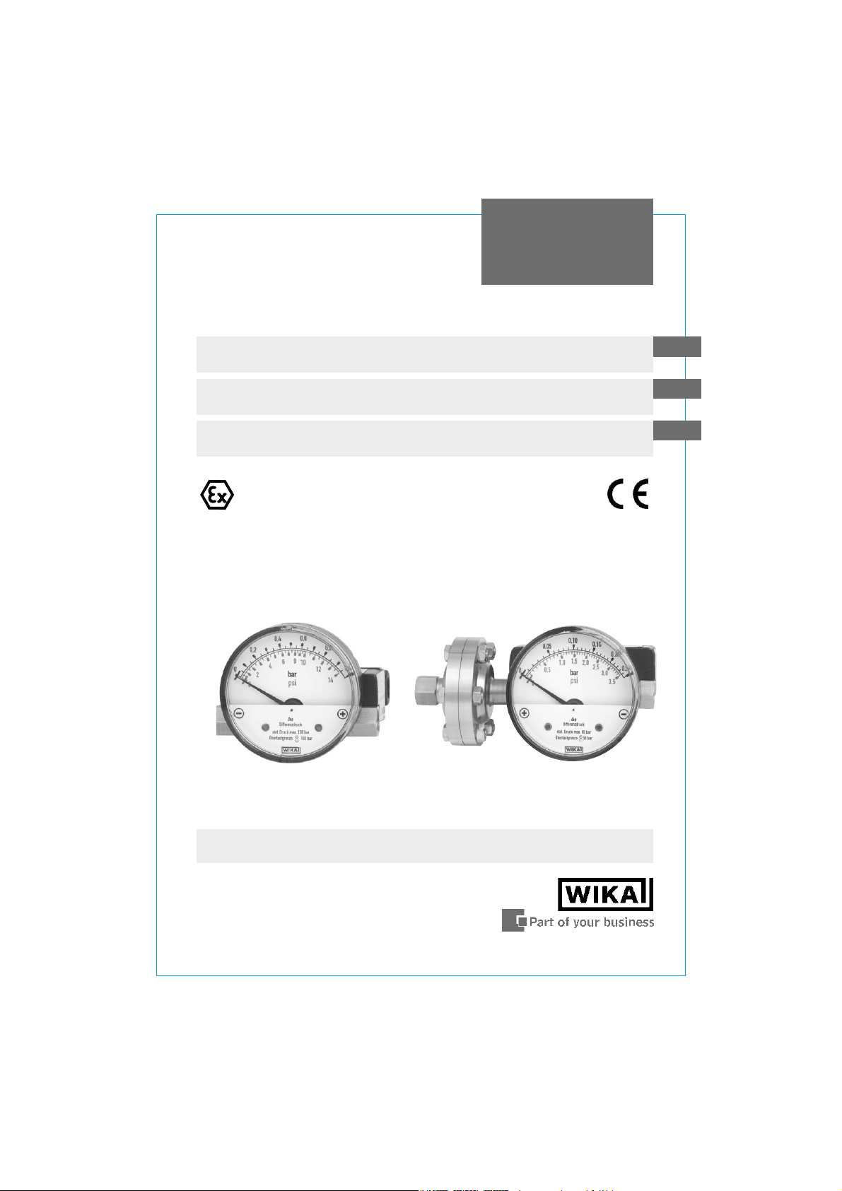
Model 700.01.80 per ATEX with
alarm contacts Model 851.3
Model 700.02.80 per ATEX with
alarm contacts Model 851.3
Page 2
GB
Operating instructions Model 700.0X per ATEX
with Model 851 Page 1-11
Betriebsanleitung Typ 700.0X nach ATEX
D
mit Typ 851 Seite 13-21
Instructions d'utilisation Type 700.0X selon ATEX
F
avec Type 851 Page 23-31
2 WIKA Operating instructions pressure gauges Model 700.0X with 851 per ATEX
11025867 02/2005 GB/D/F
Page 3
Contents
Contents
Contents
1. Safety instructions 4
2. Description and operating principle 4
3. Technical data and intended use 5
4. Requirements for use in potentially explosive
atmospheres 6
5. Installation 7
6. Commissioning 8
7. Optional extras / accessories 9
8. Maintenance and servicing / cleaning 10
9. Repairs 10
10. Disposal 10
Enclosure 1: Declaration of conformity for Models 700.0X
with alarm sensors Model 851 11
GB
11025867 02/2005 GB/D/F
3WIKA Operating instructions pressure gauges Model 700.0X with 851 per ATEX
Page 4
1. Safety instructions / 2. Description and operating principle
1. Safety instructions
!
Caution
GB
The appropriate national safety regulations (i.e. VDE 0100 /
EN 60 079-14 / EN 837-2) must be observed when installing,
putting into operation and running these instruments.
T Do not work on gauge while under voltage
T Serious injuries and/or damage can occur should the appropriate
regulations not be observed
€T Only appropriately qualified persons should work on these
instruments
2. Description and operating principle
The pressure gauges measure the pressure differential between two connection
points by means of a piston loaded on both sides, which is supported by a
compression spring. Depending on the differential pressure measured the
optional alarm contact switches as soon as the set switch point is reached.
T Pressures p
separated by a magnetic piston under pressure (resp. magnetic piston and
separation diaphragm for model 700.02).
T The difference in pressure causes an axial movement (measuring travel) of
the piston supported by the compression spring.
T The measuring path resulting from this is taken up by a ring magnet found
on the instrument pointer and appropriately displayed. This design combines
the advantage of a complete separation of the measuring system and the
indication and eliminates any leakage to the exterior.
T For model 700.01 the stream of volume from the j measuring chamber to
the i measuring chamber is minimized by the constructive design and will
not interfere with the process.
These measuring instruments are mainly intended for gas / air supply and
preparation applications where no magnetic particles are involved.
In processes with floating particles model 700.02 should be used.
Further information on the gauge design see data sheet PM 07.14
4 WIKA Operating instructions pressure gauges Model 700.0X with 851 per ATEX
and p2 are given in the j and i measuring chambers
1
11025867 02/2005 GB/D/F
Page 5
3. Technical data and intended use
3. Technical data and intended use
Static pressure / Overpressure safety maximum
Model Working pressure Overpressure safe
Pressure ranges max. either side
(static pressure)
Model 700.01:
0 ... 400 mbar to 0 ... 10 bar optionally 100, 250 to maximum
or 400 bar working pressure
Typ 700.02:
0 ... 160 mbar and 0 ... 250 mbar 50 bar 50 bar
0 ... 400 mbar and 0 ... 2.5 bar 100 bar 50 bar
Pressure connection
T According to the general technical regulations for pressure gauges,
respectively (i.e. EN 837-2 "Selection and installation recommendations for
pressure gauges").
When screw-fitting the gauges the force required for sealing must not be
applied through the case or terminal box but, using a suitable tool, only through
the spanner flats provided for this purpose at the square of the connector.
IP Ingress protection
IP 54 per EN 60 529 / IEC 60 529
Permissible vibratory stress at the mounting location
GB
T As a matter of principle the instruments should only be mounted at locations
without vibratory stresses
T Where required, a decoupling from the mounting location can be achieved
e.g. by a flexible connecting line from the measuring point to the pressure
gauge and mounting via a measuring instrument bracket.
T If this is not possible, the following limits must not be exceeded:
Frequency range < 150 Hz
Acceleration < 0.7 g (7 m/s
11025867 02/2005 GB/D/F
2
)
5WIKA Operating instructions pressure gauges Model 700.0X with 851 per ATEX
Page 6
4. Requirements for use in potentially explosive atmospheres
4. Requirements for use in potentially explosive
!
Note
GB
Operating Temperature
Ambient (for use in potentially explosive atmospheres): 0 ... +60 °C
atmospheres
The built-in Reed contacts do not have their own ignition source.
They are 'simple apparatus' in terms of intrinsic safety as defined in
EN 50 020.
When supplied from a tested and certified intrinsically safe circuit
(associated apparatus), these switches may be used in potentially
explosive atmospheres up to category 2 without having to take any
further measures.
Medium: The permissible medium temperature does not only depend on the
Attention! With gaseous substances the temperature may increase as a result
of the compression temperature. In such cases the pressure change rate has to
be slowed down resp. the permissible medium temperature has to be reduced.
Permissible medium temperature
Temperature class of Permissible maximum medium
the ambient atmosphere temperature (in the pressure system)
(ignition temperature)
T 6 ( > 85 °C) +70 °C
T 5 ( > 100 °C) +85 °C
all other temperature classes +100 °C
instrument design, but also on the ignition temperature of the
surrounding explosive atmosphere. Both aspects have to be
taken into account.
Alarm contacts
Especially conceived to allow low current circuits to be switched
directly, switch point may be set by means of adjusting screws
from the exterior in a range of 10 ... 100 % of full scale value.
Max. switching voltage: 30 VDC / VAC
Max. load: 3 W
Max. strength of current: 0.2 A
Switching hysteresis: 5 % of full scale value
6 WIKA Operating instructions pressure gauges Model 700.0X with 851 per ATEX
11025867 02/2005 GB/D/F
Page 7
5. Installation
5. Installation
The installation of the differential pressure gauge is made following the
installation recommendations for pressure gauges according to EN 837-2 /7.
T The permissible maximum media / ambient temperature must not be
exceeded (see point 3)
T Prior to the installation of the pressure gauge, the pipes should be
thoroughly cleaned
T The pressure gauges should be installed and operated such as to avoid
exposure to vibrations
T The pressure gauges should be protected against contamination and high
temperature fluctuations
To avoid foreign matter in the measuring system and the resulting damage to
the system the pressure gauge is to be mounted above the connector. For
measuring media containing floating particles model 700.02 should be used.
If the line to the pressure gauge is not robust enough for vibrationless mounting
it should be fastened by means of an appropriate fastening element for wall
fitting or if necessary be made through a capillary.
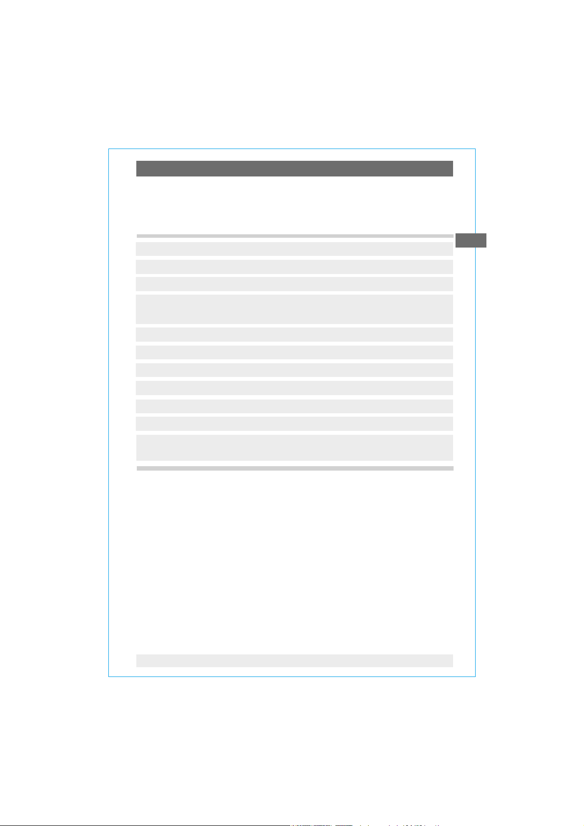
Wall mounting (see drawing)
Installation / fastening by means of mounting brackets
GB
Drag pointer
11025867 02/2005 GB/D/F
without Reed contact
with Reed contact
Slotted screw M 4 x 10
Plug
Reed case
Hexagon bolt
M 8 x 50 (M 8 x 100)
7WIKA Operating instructions pressure gauges Model 700.0X with 851 per ATEX
1581 007.02
Page 8
6. Commissioning
6. Commissioning
6.1 Mounting of the pressure connection
Pressure entries identified j and
GB
Hold against the connection pieces in the case of installation by means of
ij
high pressure
i
low pressure
17 mm screw spanner (installation by means of the screws without holding
against the connection pieces may cause the measuring system to get loose).
6.2 Wiring details
Connection of the switches via screw terminals in the terminal box.
Terminal assignment see wiring scheme below.
Conductor cross section max. 1.5 mm
2.
Wiring scheme
Reed contact
Model 851.3 and 851.3.3
851.3. 3
2nd contact
851. 3
1st contact
Attention: The instrument is to be included in the equipotential bonding of the plant!
Terminal box
The gauges do not
provide for incorporated
overcurrent protectors.
If overcurrent protectors
are requested, these have
to be provided
for externally.
6.3 Setting the switching point
Preference should be given to setting the switching point before installing the
measuring instrument. The necessary test path is generated by hand (for
example, by means of a antimagnetic screw driver).
Manual generation
of test:
Plus measuring
media chamber
antimagnetic
The switching point can be set after installation even when under pressure.
The switching point is set by turning the contact setscrew on the outside of the
reed case.
By turning anti clockwise:
switching point moves in the direction
of the start of the measuring range
By turning clockwise:
the switching point moves towards the end
of the measuring range
8 WIKA Operating instructions pressure gauges Model 700.0X with 851 per ATEX
11025867 02/2005 GB/D/F
Page 9
6. Commissioning / 7. Optional extras / accessories
6.4 To check zero point
In general the zero point is checked and set in pressureless state.
The fastening of the measuring system lug on the back of the case has to be
slackened for zero point correction. Now the zero point can be readjusted by
moving the measuring system to the right or left. After this has been done the
measuring system is to be secured again (max. tightening torque 2.5 Nm).
During the commissioning process pressure peaks must be absolutely avoided.
Open the shut-off valves slowly.
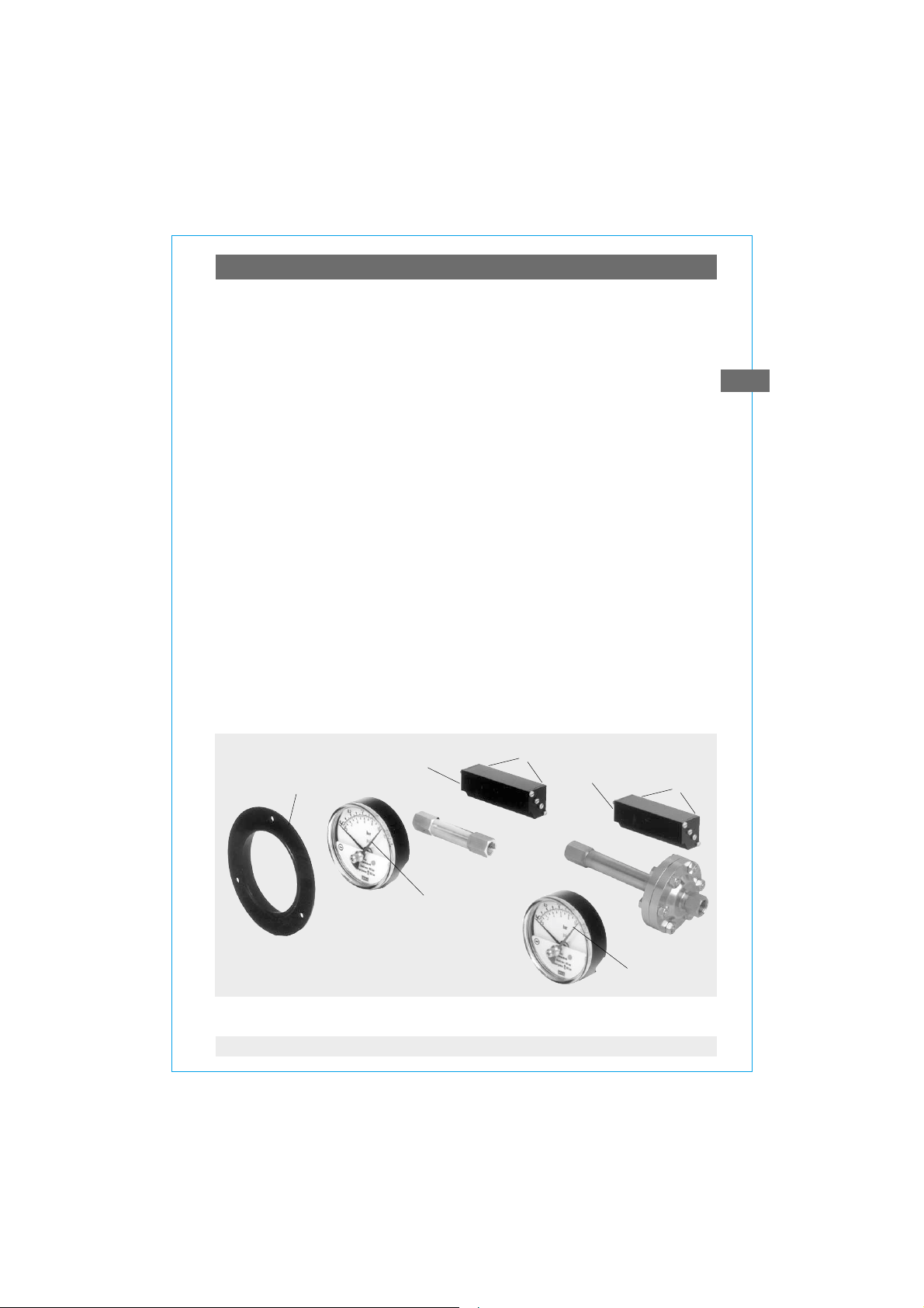
7. Optional extras / accessories
7.1 Panel mounting flange (only for model 700.01, see left picture)
The panel mounting flange may be retrofitted by the customer locally.
Alignment of the front ring (A) by means of the stamped cams to the grooves
found on the periphery of the case. Push front ring on the case until it snaps into
position.
7.2 Minimum or maximum drag pointer (see pictures)
The drag pointer (B) serves to monitor and control the minimum or maximum
occurring differential pressure.
7.3 Reed contact Model 851.3 and 851.3.3 (see pictures)
The Reed contacts may be retrofitted and adjusted by the customer locally.
Fastening is by means of two screws (D) integrated in the switch case (C)
with the pertinent inner thread in the display case.
GB
11025867 02/2005 GB/D/F
C
A
D
C
D
B
B
9WIKA Operating instructions pressure gauges Model 700.0X with 851 per ATEX
Page 10

8. Maintenance and servicing / cleaning ... 7. Disposal
8. Maintenance and servicing / cleaning
The instruments require no maintenance or servicing.
The indicator and switching function should be checked once or twice every
12 months. The instrument must be disconnected from the process to check
GB
with a pressure testing device.
The instruments should be cleaned with a damp cloth moistened with soap
solution.
9. Repairs
Repairs are to be only carried out by the manufacturer or appropriately trained
personnel.
For further details see WIKA data sheet PM 07.14.
10. Disposal
Dispose of instrument components and packaging materials in accordance with
the respective waste treatment and disposal regulations of the region or country
to which the instrument is supplied.
10 WIKA Operating instructions pressure gauges Model 700.0X with 851 per ATEX
11025867 02/2005 GB/D/F
Page 11

Enclosure 1:
Konformitätserklärung
Richtlinie 94 / 9 / EG (ATEX)
Wir erklären in alle iniger Verantwortung, dass
nachstehend genannte Produkte, Differenzdruck messgeräte mit Magnetkolben, gemäß gültige m
Datenblatt mit der Richtlinie übereinstimmen und
dem Konformitätsb ewertungsverfahren
'Interne Fertigungskontrolle'
unterzogen wurden.
WIKA-Typen / WIK A models
Die Unterlagen werden aufbewah rt
unter der Aktennum mer 8000323755
bei der benannten Stelle 0032
TÜV NORD CERT
Am TÜV 1
D-30519 Hannover
Die Geräte werd en gekennzeichnet mit
Angewandte Normen:
EN 13463-1 Nicht-elektrische G eräte für den Einsatz
in explosionsgefährdeten Bereichen
- G rundlagen und Anforderungen
EN 13463-5 Schutz durch konstruktive Sicherheit "c"
Die wahlweise eingebauten Grenzsignalgeber 851
sind ‚Einfache Bet riebsmittel’ gem äß EN 50 020.
Bei Betrieb in einem geprüften und zertifizierten
eigensicheren Str omkreis dürfen sie ohne weitere
Maßnahme als Kategor ie 2-Gerät einges etzt werden.
WIKA Alexander Wiegand GmbH & Co. KG
Geschäftsbereich Prozessinstrumentierung / Division Process Instrumentation
Klingenberg, 13.01.2005
Armin Hawlik Werner Hünerth
Leiter Logistik zentrum 2 Leiter Qualitätssicherung
Manager Production and Logistics Quality Assurance Manager
700.01 / 700.02
Declaration of Conformity
Directive 94 / 9 / EC ( ATEX)
We declare under our sole responsibility that the
products mentioned below, differential pressure
gauges with magn etic piston, according to the
current data sheet correspond with the directive and
were subjected to the con formity assessm ent
procedure
'Internal Control of Production'.
Datenblatt / data shee t
PM 07.14
The dossier is reta ined
under file nr. 8000323755
at the notified bo dy 0032
TÜV NORD CERT
Am TÜV 1
D-30519 Hannover
The gauges are mark ed with
II 2 GD c
Applied standards:
EN 13463-1 Non electrical equipment for poten tially
explosive atmospheres
- Basic method and req uirements
EN 13463-5 Protection by constructional safety "c"
The optionally built-in alarm c ontacts 851
are 'Simple Apparatus' according to EN 50 020.
If they are operated in an approved and certified as
well as intrinsically-safe circuit they can be used as a
category 2- equipm ent without an y additional action .
GB
11025867 02/2005 GB/D/F
11WIKA Operating instructions pressure gauges Model 700.0X with 851 per ATEX
Page 12

12 WIKA Betriebsanleitung Druckmessgeräte Typ 700.0X mit 851 nach ATEX
11025867 02/2005 GB/D/F
Page 13

Inhalt
Inhalt
Inhalt
1. Sicherheitshinweise 14
2. Beschreibung und Funktionsprinzip 14
3. Technische Daten und bestimmungsgemäße
Verwendung 15
4. Anforderungen bei Ex-Betrieb 16
5. Montage 17
6. Inbetriebnahme 18
7. Optionen / Zubehör 19
8. Wartung / Reinigung 20
9. Reparaturen 20
10. Entsorgung 20
Anlage 1: Konformitätserklärung für Typen 700.0X
mit Grenzsignalgeber Typ 851 21
D
11025867 02/2005 GB/D/F
13WIKA Betriebsanleitung Druckmessgeräte Typ 700.0X mit 851 nach ATEX
Page 14

1. Sicherheitshinweise / 2. Beschreibung und Funktionsprinzip
1. Sicherheitshinweise
!
Vorsicht
Beachten Sie unbedingt bei Montage, Inbetriebnahme
und Betrieb dieser Geräte die entsprechenden nationalen
Sicherheitsvorschriften (z.B. VDE 0100 / EN 60 079-14 / EN 837-2).
T Alle Arbeiten dürfen nur im spannungslosen Zustand erfolgen
D
T Bei Nichtbeachten der entsprechenden Vorschriften können
schwere Körperverletzungen und / oder Sachschäden auftreten
€T Nur entsprechend qualifiziertes Personal darf an diesen Geräten
arbeiten
2. Beschreibung und Funktionsprinzip
Die Geräte messen die herrschende Druckdifferenz zwischen zwei
Anschlussstellen über einen beidseitig belasteten Kolben, der gegen eine
Druckfeder läuft. Abhängig vom gemessenen Differenzdruck schaltet der
optional mögliche Grenzwertschalter beim Überschreiten des eingestellten
Schaltpunktes.
T In der j - und i - Messstoffkammer herrschen die Drücke p
getrennt durch den druckbeaufschlagten Magnetkolben (bzw. Magnetkolben und Trennmembrane bei Typ 700.02).
T Die Druckdifferenz verursacht eine axiale Bewegung (Messweg) des Kolbens,
der sich gegen die Messbereichsfeder abstützt.
T Der sich daraus ergebende Messweg wird von einem auf dem Instrumenten-
zeiger befindlichen Ringmagneten abgegriffen und zur Anzeige gebracht.
Dieser konstruktive Aufbau verbindet den Vorteil einer vollständigen Trennung
von Messsystem und Anzeige und verhindert jegliche Leckage nach außen.
T Der Volumenstrom von der j - zur i - Messstoffkammer bei Typ 700.01 ist
aufgrund des konstruktiven Aufbaus minimal und in Regelanwendungen nicht
störend.
und p2,
1
Bewährte Anwendungen/Einsatzgebiete sind Gas- und Luftversorgung und
deren Aufbereitung, in denen keine magnetischen Partikel enthalten sind.
Befinden sich Schwebekörper im Prozess sollte der Typ 700.02 eingesetzt
werden.
Weitere Informationen zum Geräteaubau siehe Datenblatt PM 07.14
14 WIKA Betriebsanleitung Druckmessgeräte Typ 700.0X mit 851 nach ATEX
11025867 02/2005 GB/D/F
Page 15

3. Technische Daten und bestimmungsgemäße Verwendung
3. Technische Daten und bestimmungsgemäße Verwendung
Max. Betriebsdruck / Überlastbarkeit
Typ max. Betriebsdruck Überlastbarkeit
Anzeigebereiche (statischer Druck)
Typ 700.01:
0 ... 400 mbar bis 0 ... 10 bar wahlweise 100, 250 bis zum maximalen
oder 400 bar Betriebsdruck
Typ 700.02:
0 ... 160 mbar und 0 ... 250 mbar 50 bar 50 bar
0 ... 400 mbar und 0 ... 2,5 bar 100 bar 50 bar
Druckanschluss
T Entsprechend den allgemeinen technischen Regeln für Druckmessgeräte (zB.
EN 837-2 "Auswahl- und Einbauempfehlungen für Druckmessgeräte").
Beim Einschrauben der Geräte darf die zum Abdichten erforderliche Kraft nicht
über das Gehäuse oder die Kabelanschlussdose aufgebracht werden, sondern
mit geeignetem Werkzeug nur über die dafür vorgesehenen Schlüsselflächen.
IP-Schutzart
ein-, beid- und
wechselseitig
D
IP 54 nach EN 60 529 / IEC 60 529
Zulässige Schwingungsbelastung am Einbauort
T Die Geräte sollten grundsätzlich nur an Stellen ohne Schwingungsbelastung
eingebaut werden
T Gegebenenfalls kann z.B. durch eine flexible Verbindungsleitung von der
Messstelle zum Druckmessgerät und die Befestigung über eine Messgerätehalterung eine Entkopplung vom Einbauort erreicht werden.
T Falls dies nicht möglich ist, dürfen folgende Grenzwerte nicht überschritten
werden: Frequenzbereich < 150 Hz
Beschleunigung < 0,7 g (7 m/s
11025867 02/2005 GB/D/F
2
)
15WIKA Betriebsanleitung Druckmessgeräte Typ 700.0X mit 851 nach ATEX
Page 16

4. Anforderungen bei Ex-Betrieb
4. Anforderungen bei Ex-Betrieb
!
Hinweis
D
Zulässige Temperaturen
Umgebung (im Ex-Betrieb): 0 ... +60 °C
Die eingebauten Reedschalter haben keine eigene Zündquelle.
Sie sind 'Einfache Betriebsmittel' im Sinne der Eigensicherheit nach
EN 50 020.
Bei Versorgung aus einem geprüften und bescheinigten eigensicheren Stromkreis (zugehöriges Betriebsmittel) dürfen diese
Schalter ohne weitere Maßnahmen in explosionsgefährdeten
Bereichen bis Kategorie 2 eingesetzt werden.
Messstoff: Die zulässige Messstofftemperatur hängt sowohl von der Geräte-
bauart als auch von der Zündtemperatur der umgebenden
explosionsfähigen Atmosphäre ab.
Beide Aspekte sind zu berücksichtigen.
Achtung! Bei gasförmigen Stoffen kann sich die Temperatur durch Kompressionswärme erhöhen. In solchen Fällen muss ggf. die Druckänderungsgeschwindigkeit gedrosselt bzw. die zulässige Messstofftemperatur reduziert
werden.
Zulässige Messstofftemperatur
Temperaturklasse der Zulässige maximale Messstofftemperatur
umgebenden zündfähigen (im Messsystem)
Atmosphäre (Zündtemperatur)
T 6 ( > 85 °C) +70 °C
T 5 ( > 100 °C) +85 °C
alle anderen Temperaturklassen +100 °C
Elektrische Grenzsignalgeber
Insbesondere auch zum direkten Schalten von Niederstromkreisen, Schaltpunkt
mittels Kontakt-Einstellschrauben von außen im Bereich von 10 % bis 100 %
des Skalenendwertes einstellbar.
max. Schaltspannung: 30 VDC / VAC
max. Schaltleistung: 3 W
max. Stromstärke: 0,2 A
Schaltumkehrspanne: 5 % vom Skalenendwert
16 WIKA Betriebsanleitung Druckmessgeräte Typ 700.0X mit 851 nach ATEX
11025867 02/2005 GB/D/F
Page 17

5. Montage
5. Montage
Die Montage des Differenzdruck-Messgerätes erfolgt in Anlehnung an die
Einbauempfehlungen für Druckmessgeräte nach EN 837-2 /7.
T Die zulässige Messstoff-/Umgebungstemperatur darf nicht
überschritten werden (siehe Punkt 3)
T Messleitungen vor der Gerätemontage gründlich reinigen
T Messgeräte sollen erschütterungsfrei montiert und betrieben werden
T Messgeräte sollen vor Verschmutzung und starken Temperatur-
schwankungen geschützt sein
Um Fremdkörper im Messsystem und somit eine Beschädigung desselben zu
vermeiden, ist das Druckmessgerät oberhalb des Entnahmestutzens anzubringen. Für schwebekörperhaltige Messstoffe ist der Typ 700.02 vorzusehen.
Ist die Leitung zum Druckmessgerät für eine erschütterungsfreie Anbringung
nicht stabil genug, so ist die Befestigung über entsprechende Befestigungselemente für Wandmontage oder ggf. über eine Kapillare vorzunehmen.
Montage an Wand (siehe Zeichnung)
Anbringung/Befestigung mittels Messgerätehalter
Sechskantschraube
M 8 x 50 (M 8 x 100)
Schleppzeiger
ohne Reedkontakt
mit Reedkontakt
Schlitzschraube M 4 x 10
D
11025867 02/2005 GB/D/F
Stecker
Reedgehäuse
1581 007.02
17WIKA Betriebsanleitung Druckmessgeräte Typ 700.0X mit 851 nach ATEX
Page 18

6. Inbetriebnahme
6. Inbetriebnahme
6.1 Montage des Druckanschlusses
Nach angebrachten Symbolen j und
ij
hoher Druck
i
niedriger Druck
Bei Montage mittels Schraubenschlüssel SW 17 an den Anschlussstücken gegen-
halten (Einschrauben ohne gegenhalten kann zur Lockerung des Messsystems führen).
D
6.2 Elektrischer Anschluss
Der Anschluss der Schalter erfolgt über Schraubklemmen in der Kabeldose.
Klemmenbelegung siehe nachfolgendes Anschlussschema.
Leitungsquerschnitt max. 1,5 mm
Anschlussschema
Reed-Kontakt
Typ 851.3 und 851.3.3
Achtung: Das Gerät ist in den Potenzialausgleich der Anlage mit einzubeziehen!
851.3. 3
851. 3
2
.
2. Kontakt
1. Kontakt
In den Geräten sind keine
Überstrom-Schutzeinrichtungen eingebaut.
Falls Schutzeinrichtungen
gefordert werden, sind
diese extern vorzusehen.
Kabeldose
6.3 Schaltpunkteinstellung
Vorzugsweise erfolgt die Schaltpunkteinstellung vor dem Einbau des
Messgerätes. Der erforderliche Prüfweg wird manuell (z.B. mit Hilfe eines nicht
magnetischen Schraubendrehers) erzeugt.
Manuelle Prüfwegerzeugung:
Plusmessstoffkammer
antimagnetisch
Die Schaltpunkteinstellung kann auch im druckbeaufschlagten Zustand nach
Einbau erfolgen. Die Verstellung des Schaltpunktes erfolgt durch Drehen der
Kontakt-Einstellschrauben an der Reed-Gehäuseaußenseite.
Drehrichtung links:
Schaltpunkt verschiebt sich in Richtung
Messbereichsanfang
Drehrichtung rechts:
Schaltpunkt verschiebt sich in Richtung
Messbereichsende
18 WIKA Betriebsanleitung Druckmessgeräte Typ 700.0X mit 851 nach ATEX
11025867 02/2005 GB/D/F
Page 19

6. Inbetriebnahme / 7. Optionen/Zubehör
6.4 Nullpunktprüfung
Üblicherweise erfolgt die Überprüfung und Einstellung des Nullpunktes im
drucklosen Zustand.
Zur Nullpunktkorrektur ist die Befestigung des Messystems an der Gehäuserückseite zu lockern. Der Nullpunkt lässt sich jetzt durch Verschieben des
Messsystems nach rechts oder links nachjustieren.
Anschließend muss das Messsystem wieder fixiert werden (Anzugsmoment
max. 2,5 Nm).
Bei der Inbetriebnahme Druckstöße unbedingt vermeiden,
Absperrventile langsam öffnen.
7. Optionen/Zubehör
7.1 Befestigungsrand (nur bei Typ 700.01, siehe Darstellung links)
Vor Ort nachrüstbar.
Ausrichten des Frontringes (A) über eingeprägte Nocken zu am Gehäuseumfang
befindlichen Nuten. Frontring auf Gehäuse bis zum Einschnappen aufschieben.
7.2 Minimum- bzw. Maximum-Schleppzeiger (siehe Darstellungen)
Schleppzeiger (B) dient zur Überwachung und Kontrolle des minimalen bzw.
maximalen aufgetretenen Differenzdruckes.
7.3 Reed-Kontakt Typ 851.3 und 851.3.3 (siehe Darstellungen)
Vor Ort nachrüst- und einstellbar.
Die Befestigung erfolgt über zwei im Schaltergehäuse (C) integrierte Schrauben
(D) und die zugehörigen Innengewinde im Anzeigegehäuse.
D
11025867 02/2005 GB/D/F
C
A
D
C
D
B
B
19WIKA Betriebsanleitung Druckmessgeräte Typ 700.0X mit 851 nach ATEX
Page 20

8. Wartung / Reinigung ... 10. Entsorgung
8. Wartung / Reinigung
Die Geräte sind wartungsfrei.
Eine Überprüfung der Anzeige und der Schaltfunktion sollte etwa 1 bis 2 mal
pro Jahr erfolgen. Dazu ist das Gerät vom Prozess zu trennen und mit einer
Druckprüfvorrichtung zu kontrollieren.
Reinigen der Geräte mit einem (in Seifenlauge) angefeuchteten Tuch.
D
9. Reparaturen
Reparaturen sind ausschließlich vom Hersteller oder entsprechend geschultem
Personal durchzuführen.
Weitere technische Daten bitte dem WIKA Datenblatt PM 07.14 entnehmen.
10. Entsorgung
Entsorgen Sie Gerätekomponenten und Verpackungsmaterialien entsprechend
den einschlägigen landesspezifischen Abfallbehandlungs- und Entsorgungsvorschriften des Anliefergebietes.
20 WIKA Betriebsanleitung Druckmessgeräte Typ 700.0X mit 851 nach ATEX
11025867 02/2005 GB/D/F
Page 21

Anlage 1:
Konformitätserklärung
Richtlinie 94 / 9 / EG (ATEX)
Wir erklären in alle iniger Verantwortung, dass
nachstehend genannte Produkte, Differenzdruck messgeräte mit Magnetkolben, gemäß gültige m
Datenblatt mit der Richtlinie übereinstimmen und
dem Konformitätsb ewertungsverfahren
'Interne Fertigungskontrolle'
unterzogen wurden.
WIKA-Typen / WIK A models
Die Unterlagen werden aufbewah rt
unter der Aktennum mer 8000323755
bei der benannten Stelle 0032
TÜV NORD CERT
Am TÜV 1
D-30519 Hannover
Die Geräte werd en gekennzeichnet mit
Angewandte Normen:
EN 13463-1 Nicht-elektrische G eräte für den Einsatz
in explosionsgefährdeten Bereichen
- G rundlagen und Anforderungen
EN 13463-5 Schutz durch konstruktive Sicherheit "c"
Die wahlweise eingebauten Grenzsignalgeber 851
sind ‚Einfache Bet riebsmittel’ gem äß EN 50 020.
Bei Betrieb in einem geprüften und zertifizierten
eigensicheren Str omkreis dürfen sie ohne weitere
Maßnahme als Kategor ie 2-Gerät einges etzt werden.
WIKA Alexander Wiegand GmbH & Co. KG
Geschäftsbereich Prozessinstrumentierung / Division Process Instrumentation
Klingenberg, 13.01.2005
Armin Hawlik Werner Hünerth
Leiter Logistik zentrum 2 Leiter Qualitätssicherung
Manager Production and Logistics Quality Assurance Manager
700.01 / 700.02
Declaration of Conformity
Directive 94 / 9 / EC ( ATEX)
We declare under our sole responsibility that the
products mentioned below, differential pressure
gauges with magn etic piston, according to the
current data sheet correspond with the directive and
were subjected to the con formity assessm ent
procedure
'Internal Control of Production'.
Datenblatt / data shee t
PM 07.14
The dossier is reta ined
under file nr. 8000323755
at the notified bo dy 0032
TÜV NORD CERT
Am TÜV 1
D-30519 Hannover
The gauges are mark ed with
II 2 GD c
Applied standards:
EN 13463-1 Non electrical equipment for poten tially
explosive atmospheres
- Basic method and req uirements
EN 13463-5 Protection by constructional safety "c"
The optionally built-in alarm c ontacts 851
are 'Simple Apparatus' according to EN 50 020.
If they are operated in an approved and certified as
well as intrinsically-safe circuit they can be used as a
category 2- equipm ent without an y additional action .
D
11025867 02/2005 GB/D/F
21WIKA Betriebsanleitung Druckmessgeräte Typ 700.0X mit 851 nach ATEX
Page 22

22 WIKA Betriebsanleitung Druckmessgeräte Typ 700.0X mit 851 nach ATEX
11025867 02/2005 GB/D/F
Page 23

Sommaire
Sommaire
Sommaire
1. Conseils de sécurité 24
2. Description et principe de fonctionnement 24
3. Caractéristiques techniques et utilisation
correspondante 25
4. Exigences pour l'utilisation en service sous
danger d'explosion 26
5. Montage 27
6. Mise en service 28
7. Options / accessoires 29
8. Maintenance / nettoyage 30
9. Réparations 30
10. Mise au rebus 30
Annexe 1: Déclaration de Conformité des types 700.0X
avec contact électrique type 851 (allemand / anglais) 31
F
11025867 02/2005 GB/D/F
23WIKA Instructions d'utilisation manomètres Type 700.0X avec 851 selon ATEX
Page 24

1. Conseils de sécurité / 2. Description et principe de ...
1. Conseils de sécurité
!
Avertissement
F
Les prescriptions de sécurité nationales en vigueur (par exemple
VDE 0100 / EN 60 079-14 / EN 837-2) doivent absolument être
respectées lors du montage, de la mise en service et de
l'utilisation des instruments ici présentés.
T Toutes les interventions doivent être effectuées hors tension
€T Le non-respect des instructions correspondantes est
susceptible d'entraîner des risques de blessure et/ou des
dégâts matériels
€T Seul le personnel habilité et qualifié est autorisé à manipuler
les instruments
2. Description et principe de fonctionnement
Les appareils mesurent la différence de pression existante entre deux points de
raccord, par l'intermédiaire d'un piston mis sous charge bilatéralement et
appuyé par un ressort. En fonction de la différence de pression mesurée, un
seuil d'alarme en option commute en dépassant le point de commutation réglé.
T dans les chambres de mesure de fluide j et i il y a les pressions p
séparées par le piston magnétique sous charge (ou piston magnétique et
membrane de séparation pour le modèle 700.02).
T La différence de pression provoque un déplacement axial (chemin de
mesure) du piston s'appuyant contre le ressort de l'étendue de mesure.
T Le chemin de mesure en résultant est prélevé par un aimant torique se
trouvant sur l'aiguille de l'instrument et est ainsi affiché.
Ce montage associe l'avantage d'une séparation intégrale entre le système
de mesure et l'affichage et empêche toute fuite à l'extérieur.
et p2,
1
T Le débit du volume de la chambre de mesure j à la chambre i est, pour le
modèle 700.01 en raison de sa construction minime et non gênant en
utilisation normale.
Des utilisations/domaines d'applications éprouvées sont les alimentations en
gaz et en air ne contenant aucune particule magnétique.
Il faut utiliser le modèle 700.02 si des matières en suspension se trouvent dans
le processus.
Pour d'autres informations sur la construction de l'appareil, veuillez consulter la
fiche technique PM 07.14.
24 WIKA Instructions d'utilisation manomètres Type 700.0X avec 851 selon ATEX
11025867 02/2005 GB/D/F
Page 25

3. Caractéristiques techniques et utilisation correspondante
3. Caractéristiques techniques et utilisation correspondante
Pression maxi / limite de surcharge
Type Pression maxi Surcharge
Etendues de mesure (pression statique) bi-latérale
Type 700.01:
0 ... 400 mbar à 0 ... 10 bar au choix 100, 250 jusqu’à la pression
ou 400 bar maximale
Type 700.02:
0 ... 160 mbar et 0 ... 250 mbar 50 bar 50 bar
0 ... 400 mbar et 0 ... 2,5 bar 100 bar 50 bar
Raccord de pression
T Conformément aux règles techniques générales pour les manomètres (par
exemple EN 837-2 "Recommandations sur le choix et l'installation des
manomètres").
Lors de l'opération de vissage des appareils de mesure, la force nécessaire ne
doit pas être appliquée sur le boîtier ou sur la prise câblée, mais seulement sur
les surfaces prévues par un outil approprié sur le carré du raccord.
F
IP Degré de protection
IP 54 selon EN 60 529 / IEC 60 529
Contrainte de vibration admissible sur le point de montage
T Les appareils ne devraient en principe être installés que sur des applications
exemptes de vibrations
T Le cas échéant, on peut atteindre un découplage du point de mesure
en utilisant une liaison flexible au manomètre et en le fixant à l'aide
d'un support d'appareil mural.
T Dans le cas où cela n'est pas possible, les valeurs suivantes ne doivent
pas être dépassées: Plage de fréquence < 150 Hz
Accélération < 0,7 g (7 m/s
11025867 02/2005 GB/D/F
2
)
25WIKA Instructions d'utilisation manomètres Type 700.0X avec 851 selon ATEX
Page 26

4. Exigences pour l'utilisation en atmosphères sous risque ...
4. Exigences pour l'utilisation en atmosphères sous
!
Note
F
Températures autorisées
Ambiante (pour utilisation sous danger d'explosion): 0 ... +60 °C
risque d'explosion
Les contacteurs de reed ne possèdent pas de source
d'inflammation propres. Ils sont du "matériel électrique simple"
dans le sens de la sécurité intrinsèque selon EN 50 020.
En cas d'alimentation à partir d'un circuit en sécurité intrinsèque
examiné et homologué (matériel électrique affilié), ces contacteurs
peuvent, sans autres mesures, être utilisés dans des zones sous
danger d'explosion jusqu'à la catégorie 2.
Fluide: La température de fluide autorisée dépend, en plus de la conception
Attention! Pour les fluides gazeux la température peut s'élever par le biais
d'une température de compression. Dans ces cas il faut, soit limiter la vitesse
d'élévation de la pression, soit réduire la température de fluide admissible.
Température de fluide admissible
Classe de température Température maximale autorisée du fluide
de l'atmosphère environnante (dans le système de mesure)
(température d'inflammation)
T 6 ( > 85 °C) +70 °C
T 5 ( > 100 °C) +85 °C
toutes les autres classes de température +100 °C
de l'appareil, également de la température d'inflammation de
l'atmosphère explosible de l'environnement.
Ces deux paramètres sont à prendre en considération.
Contacts électriques
Particulièrement indiqué pour commuter des circuits basse tension. Point de
commutation réglable de l'extérieure par vis de positionnement dans une plage
de 10% à 100 % de la fin d'échelle.
Tension maxi de commutation: 30 Vcc / Vca
Puissance maxi de commutation: 3 W
Courant maxi de commutation: 0,2 A
Écart dû au renversement: 5 % de la fin d'échelle
26 WIKA Instructions d'utilisation manomètres Type 700.0X avec 851 selon ATEX
11025867 02/2005 GB/D/F
Page 27

5. Montage
5. Montage
Le montage du manomètre différentiel se fait en se reportant aux
recommandations d'installation d'appareils de mesure de pression selon EN
837-2/7.
T La température admissible pour le fluide / l'ambiance ne doit pas être
dépassée (voir point 3).
T Nettoyer soigneusement les conduites de mesure avant de monter l'appareil.
T Les appareils doivent être installés et utilisés exempts de vibrations.
T Les appareils doivent être protégés contre la crasse et de fortes variations
de température.
Afin d'éviter que des impuretés pénètrent dans le système de mesure et de là
une détérioration de celui-ci, le manomètre est à placer au-dessus du point de
mesure.
Au cas où le tuyau raccordant le manomètre ne serait pas suffisamment stable
pour une fixation exempte de vibrations, il faut effectuer la fixation à l'aide
d'éléments pour installation sur paroi ou, le cas échéant, par l'intermédiaire d'un
tube capillaire.
Montage sur paroi (voir dessin)
Pose / fixation à l'aide d'un support d'appareil de mesure
vis à tête hexagonal
M 8 x 50 (M 8 x 100)
aiguille suiveuse
sans contact de reed
avec contact de reed
vis à tête fendue M 4 x 10
connecteur
F
11025867 02/2005 GB/D/F
boîtier de reed
1581 007.02
27WIKA Instructions d'utilisation manomètres Type 700.0X avec 851 selon ATEX
Page 28

6. Mise en service
6. Mise en service
6.1 Montage du raccord pression
Selon les symboles marqués j et
Lors du montage maintenir les raccords sur l'appareil au moyen d'une clé à fourche de 17
(un vissage sans cette précaution peut conduire à un desserrement du système de mesure).
ij
haute pression
i
basse pression
6.2 Raccords électriques
Le branchement des contacts se fait bar des bornes dans la boîte de jonction.
Pour la codification des borniers voir le schéma de raccord ci-après
F
La section des conducteurs est de maxi 1,5 mm
Schéma de branchement
Contact de reed
Modèle 851.3 et 851.3.3
851.3. 3
2ème contact
851. 3
1er contact
Attention: L'appareil est à inclure dans la compensation de potentiel de l'installation!
2.
Aucun dispositif de
protection de surtension
n'est installé dans les
appareils. Au cas où des
dispositifs de protection
sont exigés, ceux-ci sont
à prévoir à l'extérieur.
Boîte de jonction
6.3 Réglage du point de commutation
De préférence, le réglage du point de commutation doit se faire avant le
montage de l'appareil. Le contrôle du déplacement se fait manuellement (par
exemple à l'aide d'un tournevis non magnétique).
Contrôle manuel
du déplacement
chambre de mesure
positive
antimagnétique
Le réglage du point de commutation peut aussi être fait sous pression, après le
montage. Le réglage se fait en tournant les vis de réglage de commutation du
contact à l'extérieur du boîtier de reed.
Sens de rotation à gauche:
Le point de commutation se déplace en direction
du début de l'étendue de mesure
Sens de rotation à droite :
Le point de commutation se déplace en direction
de la fin de l'étendue de mesure
28 WIKA Instructions d'utilisation manomètres Type 700.0X avec 851 selon ATEX
11025867 02/2005 GB/D/F
Page 29

6. Mise en service / 7. Options / accessoires
6.4 Contrôle du zéro
Habituellement le contrôle et le réglage du zéro se font sans pression.
Pour corriger le zéro, il faut desserrer la fixation du système de mesure à
l'arrière du boîtier. Maintenant le zéro peut être corrigé en déplaçant le système
de mesure à gauche ou à droite.
Ensuite le système de mesure doit être de nouveau fixé (couple de serrage
maxi 2,5 Nm).
Lors de la mise en service il faut absolument éviter les coups de bélier.
Ouvrir lentement les vannes de fermeture.
7. Options / accessoires
7.1 Collerette de fixation (uniquement pour le modèle 700.01, voir
description à gauche)
Extension faisable sur site.
Aligner les ergots empreints de la collerette (A) aux rainures sur la circonférence
du boîtier. Enfoncer la collerette jusqu'à l'encliquetage.
7.2 Aiguille suiveuse mini ou maxi (voir descriptions)
L'aiguille suiveuse (B) sert à la surveillance et le contrôle de la pression
différentielle minimale ou maximale présente.
7.3 Contact de reed modèle 851.3 et 851.3.3 (voir descriptions)
Extension faisable et réglable sur site.
La fixation s'effectue à l'aide de deux vis intégrées au boîtier du commutateur
(D) et le taraudage correspondant dans le boîtier de l'affichage.
C
A
B
D
C
D
F
11025867 02/2005 GB/D/F
B
29WIKA Instructions d'utilisation manomètres Type 700.0X avec 851 selon ATEX
Page 30

8. Maintenance / Nettoyage ... 10. Mise au rebus
8. Maintenance / Nettoyage
Les instruments ne requièrent aucune maintenance.
Un contrôle de l'affichage et des fonctions de commande est recommandé 1 à
2 fois/an. Pour le contrôle de l'affichage et des fonctions de commande, il faut
isoler l'appareil du processus de mesure et le contrôler avec un dispositif de
contrôle de pression.
Nettoyer les instruments avec un chiffon légèrement humidifié avec de l'eau et
du savon de Marseille.
F
9. Réparations
Toute réparation doit être exclusivement confiée au fabricant ou au personnel
qualifié correspondant.
Pour autres données, se reporter à la fiche type WIKA PM 07.14.
10. Mise au rebus
Mettez les composants des appareils et les emballages au rebus en respectant
les prescriptions nationales pour le traitement et la mise au rebus des régions
de livraison.
30 WIKA Instructions d'utilisation manomètres Type 700.0X avec 851 selon ATEX
11025867 02/2005 GB/D/F
Page 31

Annexe 1:
Konformitätserklärung
Richtlinie 94 / 9 / EG (ATEX)
Wir erklären in alle iniger Verantwortung, dass
nachstehend genannte Produkte, Differenzdruck messgeräte mit Magnetkolben, gemäß gültige m
Datenblatt mit der Richtlinie übereinstimmen und
dem Konformitätsb ewertungsverfahren
'Interne Fertigungskontrolle'
unterzogen wurden.
WIKA-Typen / WIK A models
Die Unterlagen werden aufbewah rt
unter der Aktennum mer 8000323755
bei der benannten Stelle 0032
TÜV NORD CERT
Am TÜV 1
D-30519 Hannover
Die Geräte werd en gekennzeichnet mit
Angewandte Normen:
EN 13463-1 Nicht-elektrische G eräte für den Einsatz
in explosionsgefährdeten Bereichen
- G rundlagen und Anforderungen
EN 13463-5 Schutz durch konstruktive Sicherheit "c"
Die wahlweise eingebauten Grenzsignalgeber 851
sind ‚Einfache Bet riebsmittel’ gem äß EN 50 020.
Bei Betrieb in einem geprüften und zertifizierten
eigensicheren Str omkreis dürfen sie ohne weitere
Maßnahme als Kategor ie 2-Gerät einges etzt werden.
WIKA Alexander Wiegand GmbH & Co. KG
Geschäftsbereich Prozessinstrumentierung / Division Process Instrumentation
Klingenberg, 13.01.2005
Armin Hawlik Werner Hünerth
Leiter Logistik zentrum 2 Leiter Qualitätssicherung
Manager Production and Logistics Quality Assurance Manager
700.01 / 700.02
Declaration of Conformity
Directive 94 / 9 / EC ( ATEX)
We declare under our sole responsibility that the
products mentioned below, differential pressure
gauges with magn etic piston, according to the
current data sheet correspond with the directive and
were subjected to the con formity assessm ent
procedure
'Internal Control of Production'.
Datenblatt / data shee t
PM 07.14
The dossier is reta ined
under file nr. 8000323755
at the notified bo dy 0032
TÜV NORD CERT
Am TÜV 1
D-30519 Hannover
The gauges are mark ed with
II 2 GD c
Applied standards:
EN 13463-1 Non electrical equipment for poten tially
explosive atmospheres
- Basic method and req uirements
EN 13463-5 Protection by constructional safety "c"
The optionally built-in alarm c ontacts 851
are 'Simple Apparatus' according to EN 50 020.
If they are operated in an approved and certified as
well as intrinsically-safe circuit they can be used as a
category 2- equipm ent without an y additional action .
F
11025867 02/2005 GB/D/F
31WIKA Instructions d'utilisation manomètres Type 700.0X avec 851 selon ATEX
Page 32

Technical alteration rights reserved.
Technische Änderungen vorbehalten.
Sous réserve de modifications techniques.
WIKA Alexander Wiegand GmbH & Co. KG
Alexander-Wiegand-Straße 30
63911 Klingenberg € Germany
Phone (+49) 93 72/132-0
Fax (+49) 93 72/132-406
E-Mail info@wika.de
www.wika.de
32 WIKA Betriebsanleitung Druckmessgeräte Typ 700.0X mit 851 nach ATEX
11025867 02/2005 GB/D/F
 Loading...