

Wieland 83.040.0103.0 Assembly Instructions
wienet
10-port unmanaged Industrial switch
UMS 8-2G
1
83.040.0103.0
Montageanleitung
Lesen Sie die Anweisungen vollständig und sorgfältig, bevor Sie mit dem Gerät
arbeiten.
WARNUNG
•
Elektrische Installationen, Inbetriebnahme- und Wartungsarbeiten dürfen nur
von ausgebildeten Elektrofachkräften mit einschlägiger UnfallverhütungsAusbildung und unter Beachtung der gültigen Vorschriften durchgeführt werden.
•
Schutzmaßnahmen und Schutzeinrichtungen müssen den gültigen Vorschriften
entsprechen.
•
Beschädigte Produkte dürfen weder installiert noch in Betrieb genommen
werden.
•
Das Gerät darf nicht geöffnet werden.
•
Führen Sie keine Fremdobjekte in das Gerät ein!
•
Halten Sie das Gerät von Wasser und Feuer fern!
A) Sicherheitshinweise
Vor Betrieb des Gerätes müssen folgende Bedingungen erfüllt sein:
•
Anschluß an Hauptstromversorgung in Übereinstimmung mit VDE0100 und
EN50178.
Stellen Sie vor Inbetriebnahme sicher, dass das Gerät einwandfrei installiert und
angeschlossen ist.
HINWEIS
B) Bestimmungsgemäßer Gebrauch
Verwenden Sie das Gerät nur gemäß seiner Bestimmung. Beachten Sie dazu
insbesondere die Angaben in den Technischen Daten.
C) Funktion
Das Gerät untestützt sechs 10/100base-TX Fast Ethernet, und zwei
10/100/1000BASE-TX Gigabit Ethernet-Verbindungen mit RJ-45- Anschlüssen. Sie
können einzelne Geräte oder ganze Netzwerk-Segmente anschließen.
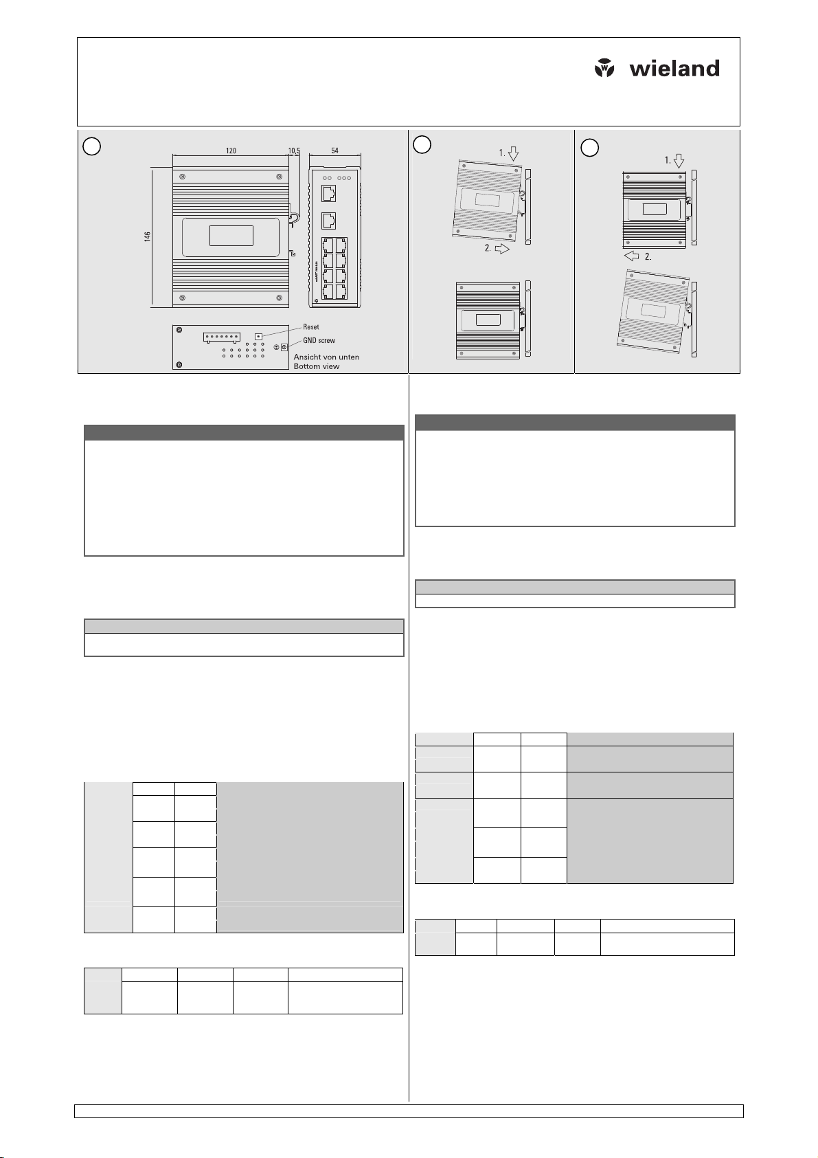
D) Funktionselemente und Anzeigen
LEDs
Name LED Status Beschreibung
P1/P2
Fault
Port 9/10
RJ45
Gelb 10Mbit Übertragungsrate
= aus; = an;• = blinkt
Versorgungsanschlüsse
Pin G V1+, V2+ V1-, V2- Schaltausgang (Relais)
Signal
Reset-Knopf
Setzt das Gerät in den Grundzustand zurück.
Grün
Grün
Grün
Grün
Masse 12…48 V DC 0 V Öffner.
Stromversorgung 1/2 nicht angeschlossen
Stromversorgung i.O.
Sowohl P1 als auch P2 an oder aus
Entweder P1 oder P2 an
Keine Verbindung
Datenverkehr
•
Keine Verbindung
Datenverkehr
•
100Mbit Übertragungsrate
Warnt bei Ausfall einer
Spannungsversorgung
E) Installation
Anbringen auf Trägerschiene (Bild 2)
•
Kippen Sie das Gerät etwas nach hinten.
•
Haken Sie das Gerät oben auf der Schiene ein.
Doc. # BA000678
Wieland Electric GmbH
Brennerstraße 10-14
96052 Bamberg
Tel.: +49 (951) 9324-0
Fax: +49 (951) 9324-198
Internet: www.wieland-electric.com
Email: info@wieland-electric.com
2
©2008 Wieland Electric GmbH
3
02/2010 (Rev. A)
4 5 6
Installation instructions
Read these instructions carefully and completely before working with this unit.
WARNING
•
Electrical installations, commissioning and maintenance work must only be
performed by qualified electricians with relevant accident prevention training
and in compliance with the applicable regulations.
•
Safety precautions and safety devices must comply with the applicable regulations.
•
Damaged products must neither be installed nor put into operation.
•
The unit must not be opened.
•
Do not introduce any objects into the unit!
•
Keep away from fire and water!
A) Safety Notes
Before operation the following conditions must be fulfilled:
•
Connection to main power supply in compliance with VDE0100 and EN50178.
Ensure appropriate installation and connection before start of operation.
NOTE
B) Intended use
Use the device only as intended. Especially observe the specifications in the
technical data.
C) Function
The device supports six 10/100BASE-TX Fast Ethernet, and two
10/100/1000BASE-TX Gigabit Ethernet connections with RJ-45 connectors. You
can connect single devices or complete network segments.
D) Functional elements and indicators
LEDs
Name LED Status Description
P1/P2
Fault
Port 9/10
RJ45
Yellow 10M rate active
= off; = on;• = flashes
Power connectors (device bottom)
Pin G V1+, V2+ V1-, V2- Relay output
Signal
Reset button
Resets the device to initial state.
Green
Red
Green
Green
Frame
12…48 V DC 0 V NC contact.
ground
Power input 1/2 is not plugged yet
Power status is Ready
Both P1 and P2 on or off
Either P1 or P2 on
No connection
Data transmission
•
No connection
Data transmission in progress
•
100M rate active
Warning for power failure.
E) Installation
Mounting on support rail (See fig. 2)
•
Tilt the unit slightly backwards.
•
Fit the unit over top hat rail.
•
Push downwards and against the rail for locking.
•
Check that the unit is locked into position.
Grounding (device bottom)
Connect the ground connection before establishing further connections. When
•
Drücken Sie das Gerät nach unten und gegen die Schiene, bis es einrastet.
•
Prüfen Sie, ob das Gerät fest auf der Tragschiene sitzt.
Erdung (Geräteunterseite)
Verbinden Sie das Gerät mit Erde, bevor Sie weitere Anschlüsse vornehmen. Wenn
Sie das Gerät deinstallieren, trennen Sie die Erdleitung als letzte.
Anschluss an Stromversorgung
Schließen Sie eine geeignete 12…48 V-Stromversorgung an das wienet UMS an.
Sie können zwei unabhängige Gleichstromquellen für eine redundante Stromversorgung anschließen. Die Versorgungsanschlüsse P1 und P2 sind galvanisch
getrennt.
Anschluß von Netzwerkgeräten
Schließen Sie Ihre Netzwerkgeräte über Standard-UTP/STP-Kabel mit RJ-45
Steckverbindern an das wienet UMS an (siehe folgende Tabelle).
Kabel Typ
10BASE-T Cat. 3,4,5
100BASE-TX Cat. 5 UTP
1000BASE-TX Cat. 5/5e UTP
Demontage (Bild 3)
Schalten Sie die Stromversorgung aus und trennen Sie das Gerät vom Netz.
Drücken Sie das Gerät nach unten, und kippen Sie es nach oben.
WARNUNG
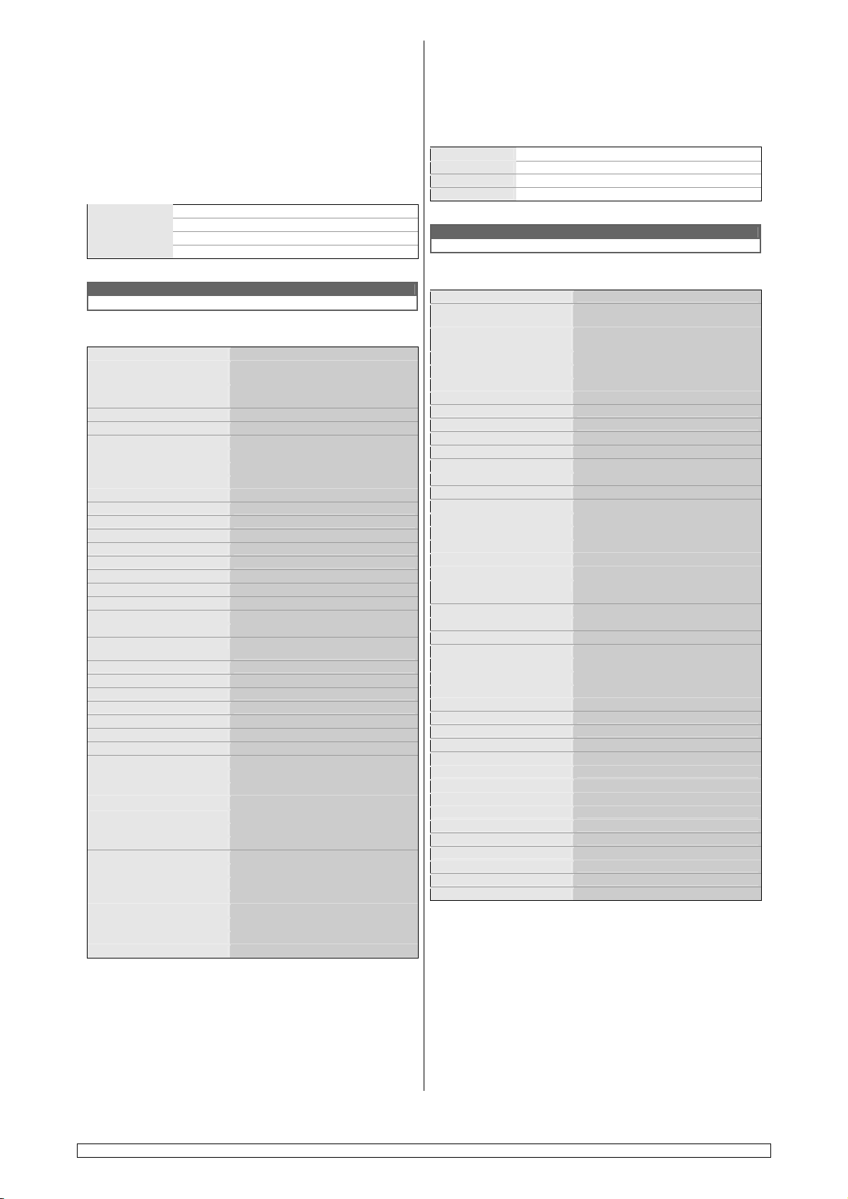
F) Technische Daten
Ethernet
Standard Fast Ethernet
Gigabit Ethernet
Übertragungsrate Fast Ethernet
Gigabit Ethernet
Anschlüsse 10 x RJ45
Auto sensing ja
Auto-Negotiation ja
Auto-Crossing (MDI / MDI-X) ja
Kommunikation Full duplex / half duplex
Ethernet-Standard IEEE 802.3 / 802.3u / 802.3x
Leitungslänge max. 100 m (Twisted Pair)
Übertragungsart Teilstreckenverfahren (store and forward)
Topologien Linie, Stern, Gitter
Stromversorgung
Redundante Stromversorgung ja (P1, P2)
Versorgungsspannung 12…48 V DC
Anschlüsse 7-pin Anschlußklemme
Leistungsaufnahme 9,5 W max.
Bemessungseingangsstrom 360 mA (bei 24 V DC)
Maximaler Eingangsstrom 1,2 A
Schaltausgang (Relais)
Art Öffner
Stromtragfähigkeit 1 A bei 24 V
Allgemeine Daten
Betriebsumgebungstemperatur -40…+70 °C (5…95 %, non-condensing)
Lagertemperatur -40…+85 ºC
Montage auf DIN rail 35 mm (EN60715)
Schutzart IP40
MTBF 201976 h
Abmessungen siehe Maßzeichnung, Bild 1.
Gewicht ca. 1000 g
Gehäusematerial Aluminium
Schock und Vibration
Schock MIL-STD-810F (40 g)
Vibration MIL-STD-810F
Stromanschlüsse
Leitergröße AWG 28-12 solid/stranded
Anschlussvermögen 0,2…1,5 mm²
Abisolierlänge 7 mm
Drehmoment 0,4 Nm max.
Normen und Zulassungen
EMV FCC Part 15 Class A, CE
Sicherheit UL, cULus
Bahntechnik EN50155, EN50121-3-2, EN50121-4
8 x 10/100Base-TX
2 x 10/100/1000/Base-TX
10/100 Mbps
10/100/1000 Mbps
(öffnet, wenn entweder P1 oder P2 fehlt)
disconnecting, ground is the last connection to be separated.
Connecting to Power
Prepare a suitable DC 12…48 V power source and connect to wienet UMS switch
by 7-pin terminal block. You can connect two DC input sources for power autobackup if necessary. The power connections P1 and P2 are galvanically isolated.
Connecting to Network Devices
Connect your devices by standard UTP/STP cable with RJ-45 connectors to wienet
UMS switch (see following table).
Cable Type
10BASE-T Cat. 3,4,5
100BASE-TX Cat. 5 UTP
1000BASE-TX Cat. 5/5e UTP
Removal from DIN Rail (see fig. 3)
Switch mains power off and disconnect your system from the supply network.
Push down the power supply, and tilt upwards.
WARNING
F) Technical Data
Ethernet
Ethernet standard Fast Ethernet
Gigabit Ethernet
Transfer rate Fast Ethernet
Gigabit Ethernet
Connectors 10 x RJ45
Auto sensing yes
Auto crossing (MDI / MDI-X) yes
Auto negotiation yes
Communication Full duplex / half duplex
Ethernet standard IEEE 802.3 / 802.3u / 802.3x
Ethernet cable length 100 m max. (Twisted Pair)
Switching mode Store-and-forward switching mode
Topologies Line, star, mesh
Power supply
Redundant power supply yes (P1, P2)
Supply voltage 12…48 V DC
Connectors 7-pin terminal block
Power consumption 9.5 W max.
Rated input current 360 mA (at 24 V DC)
Maximum input current 1,2 A
Relay output
Type NC
Current carrying capacity 1 A at 24 V
General data
Ambient operating temperature -40…+70 °C (5…95 %, non-condensing)
Storage temperature -40…+85 ºC
Mounting on DIN rail 35 mm (EN60715)
Degree of protection IP40
MTBF 201,976 h
Dimensions see dimensional drawing, fig. 1.
Weight approx. 1000 g
Housing material Aluminium
Shock and Vibration
Shock MIL-STD-810F (40 g)
Vibration MIL-STD-810F
Power Connectors
Conductor size AWG 28-12 solid/stranded
Rated conductor size 0.2…1.5 mm²
Conductor strip length 7 mm
Torque 0.4 Nm (3.5 lbf-in) max.
Approvals and Standards
EMC FCC Part 15 Class A, CE
Safety UL, cULus
Rail technology EN50155, EN50121-3-2, EN50121-4
8 x 10/100Base-TX
2 x 10/100/1000/Base-TX
10/100 Mbps
10/100/1000 Mbps
(opens when either P1 or P2 is missing)
Doc. # BA000678
 Loading...