

Page 1
®
Owner’S Guide
Sierra Super Trac
White’s Electronics, Inc. -
Manufacturers of the World’s Finest Metal Detectors
Page 2

ASSEMBLY -
Sierra Super Trac Owner’s Guide
1. Remove all parts from shipping carton and check to
make sure the kit is complete.
2. There are rubber washers between clevis/lower rod and
loop ears. Use only the provided washers, ber bolt, and
thumbnut to secure loop/search coil to clevis/lower rod.
3. Unlock rod camlocks and insert clevis/lower rod into
center rod. Center rod into curved “S” rod so that stainless
steel spring slip buttons line up and lock into one of the
adjustment holes. Turn camlock to secure.
4. Unravel Loop cable and wind the cable around the
clevis and rod assembly, rst revolution over the top of the
rod. Wind cable all the way to the top of the “S” rod, about
ve revolutions. Use the black cable retainers, one near the
loop, and one behind the display, to hold the loop cable in
place. Plug loop connector into control box and screw nger
tight to secure.
5. Unlock control box rod camlock and insert curved “S”
rod so that stainless steel spring clip buttons line up and
lock into the rod on top of the control box. The “S” rod is
designed to curve up toward the display. However, those
who prefer to sweep the loop close to their feet may desire
to assemble the “S” rod to curve down toward the ground.
Turn camlock to secure. Plug loop connector into control
box, screw lock ring to secure.
7. Remove the protective paper from the two black
elbow cup foam pads. Carefully align pads on the
inside of the elbow cup, one on each side of the
center rod, and press rmly into place.
8. Adjust the elbow cup strap so that it is loose
enough for you to slide your arm in and out without
loosening each time you want to set the detector
down. The elbow cup strap provides extra leverage
and control, however, some prefer not to use it.
9. Install battery lid decal facing down, with
plastic tab and steel contacts facing toward inside of
battery compartment.
10. It should be noted at this point that the detector
may not work as expected indoors due to the high
degree of metals used in modern construction. It is
best to tune and practice outdoors to ensure stable,
predictable results. Additionally, freshly-buried targets will not produce the normal depth and discrimination results of targets that have been naturally lost
and settled in the ground. It may take a number of
years for freshly-buried targets to respond at true
depths and discriminate accurately. The best way to
determine true detection depth is to use real search
conditions.
6. Grip the instrument by the handle, with your arm in the
elbow cup with strap secure, and sweep the loop/search
coil over the oor. If the instrument feels uncomfortable,
adjust the elbow cup by removing and repositioning the
bolt/thumbnut and installing in one of the optional posi-
tions. If necessary, re-adjust clevis/lower rod length with the
spring clip buttons so that the search coil can be held near
the oor and remain standing comfortably.
1
Page 3
Super Quick Start Instructions -
1 - 2- 3- GO
PINPOINT TRIGGER UNDER GRIP
Set to center SEARCH position
AUTO-TRAC TOGGLE
Set to Normal (initial setting triangle)
GAIN CONTROL KNOB
Set between 9 & 10 (initial setting triangle)
Sierra Super Trac Owner’s Guide
NOW
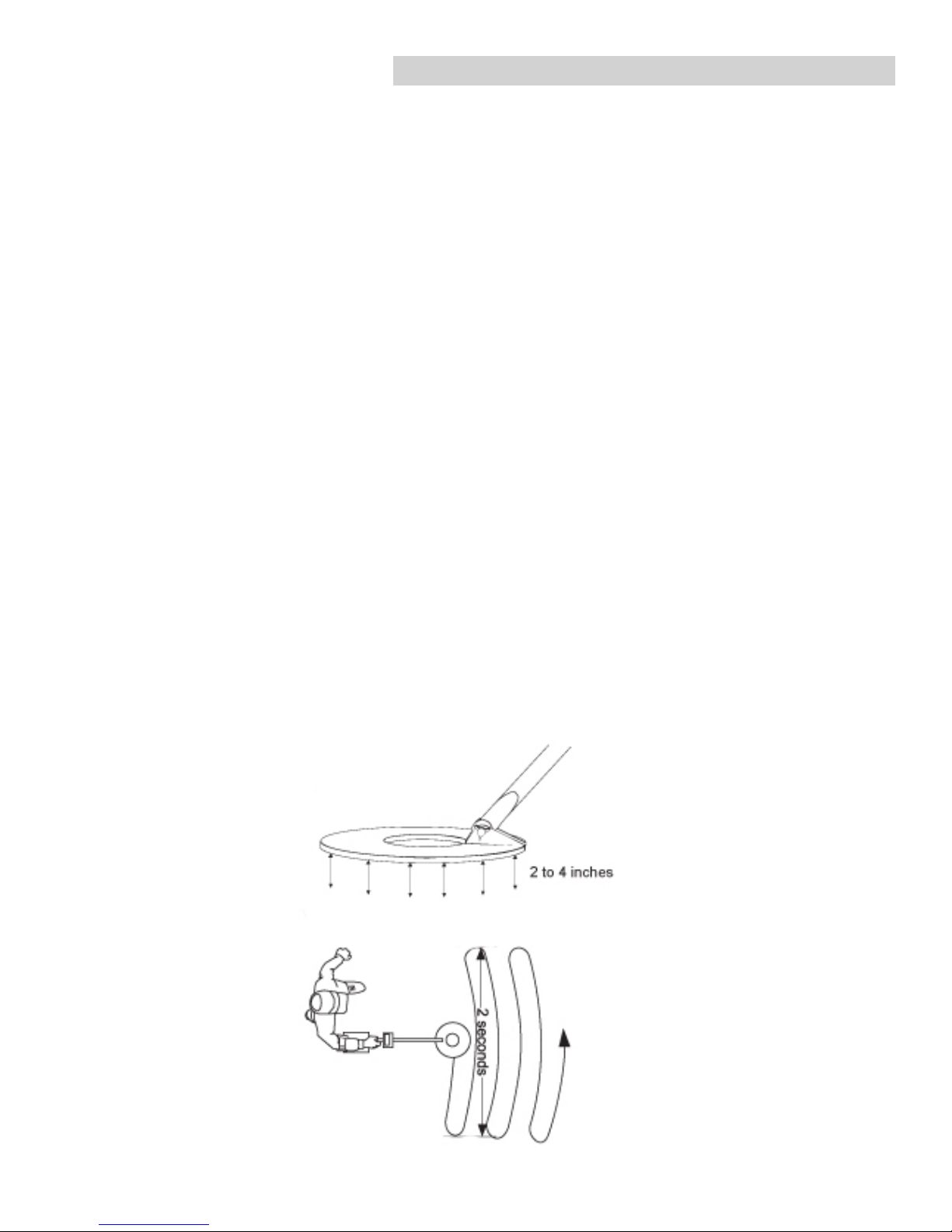
Pump the coil up and down over the ground a few times and start detecting by swinging the
search coil as indicated on the graphic drawing below.
NOW
After you nish detecting for the rst day go home and read your Owner’s Guide…
It will probably be helpful. Good luck, Jimmy Sierra
2
Page 4

Sierra Super Trac Owner’s Guide
Quick Start Instructions (full)-
1. Set the Auto Trac Toggle to the Normal “preset triangle” position.
2. Be sure the Trigger Switch (under hand grip) is in the center (search) position.
3. Turn the Gain control knob clockwise until the power clicks ON. Rotate the Gain Control clockwise to the
“preset triangle” position between 9 & 10.
4. Lower the search coil to the ground, and “pump” the coil up & down 3 or 4 times. “Auto
Trac” with automatically balance out the ground minerals.
5. You may now search the ground by swinging the search coil in wide sweeps that overlap each other,
as near to the ground as possible without scraping ground. Your “ST” is a “Silent
Search” Detector. Thus it is operating without threshold hum. You should only hear an
audio signal when passing over a target. If you do hear spurious sounds, reduce the
Gain control a bit till they go away. See a. below.
Hints
a. The “ST” is NOT speed sensitive, so you may sweep your coil over the ground as
SLOW or FAST as you prefer. However, about one second per foot is suggested. At this
point or at any time during your detecting, if you experience false signals (constant beeping or popping),
you may need to reduce (counter clockwise) the Gain control knob. Excessive mineralization or external
interference from power lines, nearby detectors, etc. Can require a lowering of the Gain (Sensitivity) a bit at a
time, until your audio operates quietly and only responds to metal targets.
b. Your “ST” is designed to hear ALL metal targets in the ground. While searching, you will be alerted to a
metal target by a repeatable audio signal when sweeping over target in both directions. The coil must be
kept in motion to hear the target. Pause slightly between sweeps to prevent tracking into the target.
c. The Audio Alert consists of a range of 7 distinct tones that correspond directly to the types of targets
indicated on the Visual Display. The lower the tone the lower the VDI number on the visual display. e.g.
The lowest tone is a Grunt for Iron or a Higher tone for a Coin. NOW!!! Look at the Visual
Display number for further identication. Negative numbers are Iron and Positive numbers are
possible good targets. If you decide to dig the target, SQUEEZE the Trigger under the hand grip
to pinpoint the target per page 5. Make certain that you keep the trigger squeezed while pinpointing. 1. to prevent tracking into the target 2. to allow the ST to pinpoint without having
to keep the coil in motion while crisscrossing over the target as described on page 4.
3
Page 5

Visual Display-
The ST display and reference label below the display provide a wealth of information about the metal target. The
display information works best after the solid repeatable
audio”beep”.
The display will momentarily show a software version and
battery voltage immediately after the SENS knob is turned
“on”. The ST operates on a twelve volt battery system, new
quality batteries will indicate 12 + volts. After 35 to 40 hours
of operation “Low Bat” will start appearing on the display at
8 volts and below. If using rechargeable batteries 8 volts is
the end of their performance. If you are using quality alkaline
batteries you do have a small reserve after 8 volts. Quality
alkaline batteries will provide extended normal performance
well after the “Low Bat” warning.
The ST provides 5 different signicant indications on the
display.
Sierra Super Trac Owner’s Guide
VDI number on display
1. VDI = number- The VDI (Visual Discrimination In-
dication) is a reference number dictated mostly by the metal
targets exact alloy, size, and shape. The reference label
below the display provides a comparison of known targets
and their common VDI numbers. Different metal targets may
share the same VDI numbers based on their electrical characteristics. VDI numbers from -95 to +94 are available and
cover the entire range of alloys and sizes.
The ST has seven distinct tone ranges that
correspond directly to the types of targets
indicated on the display. The lower the tone,
the lower the VDI number. The lowest tone is a
“grunt” on iron targets. The highest tone is on
large silver coins.
VDI number range on reference label
4
Page 6

Visual Display Continued-
Sierra Super Trac Owner’s Guide
Half block indicates target I.D. is not certain.
Note- In this case, the 1¢ is the probable ID.
2. Blocks- A series of 16 blacks appear along
the bottom portion of the display and line up with the
indications on the reference label below the display.
It is important to note these blocks are from a separate source than the VDI numbers. A second opinion
a full block indicates the ST has complete informa-
tion for target identication. A half block indicates the
ST has partial information. A quarter block indicates
the ST has only a small amount of target information.
3. Labels- The most common metal target (or
targets in some cases) within a particular Block is
listed on the display and referenced on the label
below the display. If two targets are listed, the rst
to be listed is the most common, the second is less
common than the rst.
4. Depth Indication- Trigger (on hand grip)
squeezed and held, the display indicates the depth of
coin sized metals. Starting at 12 inches and indicating in descending order (as the target gets closer to
the bottom of the search coil) the indicator provides
an aid in better locating the target in the ground (how
deep you will need to dig) and whether the metal
target is likely worth digging. Only the heavier more
valued targets get deeper into undisturbed ground.
Foil will not sink deeply into undisturbed ground.
Targets that indicate depth readings from 3-5 inches
are not as predictable.
5. PP Blocks- Trigger (on the hand grip)
squeezed and held, the PP blocks aid in pinpointing
the exact center of the metal target. When the search
coil is directly over the center of the metal target (longest possible length PP Blocks) the depth reading is
giving you the most accurate depth indication. With
some experience the relative size and shape of the
metal target can be recognized during pinpointing.
5
Page 7

Sierra Super Trac Owner’s Guide
Controls-
1. Trigger (on bottom of Hand Grip)
CENTER POSITION “Search” -
With the two position spring loaded Trigger on the hand grip in the center, the ST is in the Search Position. In this position ALL metal targets will produce an Audio Response from a menu of seven different tones
which relate to the VDI numbers which appear on the Visual Display. IRON produces the “Lowest Tone”
(Grunt) thru COINS the Highest Tones. This feature makes the detectorist immediately aware of
the likely category of the metal item without having to watch the Visual Display while searching. Each of the seven tones relates to the group of Display Categories as shown on the diagram at the bottom
of page 4. Gold jewelry will make a clearly higher tone than the Iron Grunt but Lower than the
high coin tones. After hearing the Tone Alert, THEN stop to look at the Visual Display for more informa-
tion before deciding whether or not to dig the target. Personally, I usually dig ALL targets which
are NOT clearly Iron. In this way I don’t miss any good targets. As you get more experience,
however, you will be able to sort out the different higher sounds along with watching the VDI numbers displayed on the screen and be able to ignore some of the “non iron” pieces of trash.
SQUEEZED POSITION “PINPOINTING & DEPTH READING”
After deciding you wish to dig the target, Squeeze and Hold the spring loaded Trigger on the hand
grip and crisscross the target as shown on the bottom of page 2. At this time the display will also indicate the approximate depth of a coin sized target in inches. Once released the trigger will automatically return
to the Center “Search” position.
It will also be noted, that while the Pinpoint Trigger is squeezed, the Sierra ST will STOP Track-
ing. It is very important to prevent tracking during pinpointing as repeated passes while Xing
over the target may cause the tracking system to track INTO the target and diminish the signal smaller or deeper
targets.
Trigger control
on the hand grip
Search
6
P/P
Page 8

Sierra Super Trac Owner’s Guide
Controls Continued-
2. Auto Trac Toggle (on top right face of control box)
The Auto- TRAC Toggle selects the type of ground mineral rejection (ground balance) and automatic track-
ing to ground mineral changes best suited to the specic area. Three different positions, each for a specic ground
condition are provided.
The Trac Normal position (bottom position) is used for typical ground conditions. In this position the ST will
quickly compensate for ground minerals in a few pumps of the search coil over the ground being searched and
quickly & automatically track to any ground changes as you sweep the search coil during searching. For
most operators the Trac Normal position will be used for over 90% of searching conditions.
The Trac Salt position (top position) is used on salt water beaches. This tracking position will help to re-
duce the noisy effect of the salt content of the sand. In the process, however, it can reduce the sensitivity to small
pieces of gold jewelry. This is a compromise situation, so use it if you need to quiet beach operation. You may also
try to use the Trac Off position as described below if need be.
The Trac Off (center position) monitors but does not track to changing ground conditions. This position should
be used when the ground conditions create noise and instability. This can be due to decomposing iron. It is also
valuable when ground conditions change very rapidly and tracking cannot keep up with the changes. This condition is sometimes experienced by prospectors and beach hunters.
When deciding to use this Off position, put the toggle in the Normal position or if you are at a saltwater
beach, in the Salt position and nd a quite ground area free of targets and pump the loop a few times to track
the ground and then move the toggle to the Off position. Since the tracking is Locked Off, you may from
time to time want to update the ground balance data held in memory by the Tracking software. To do
this, merely move the Auto Trac Toggle to the Normal or Salt position and then back to Trac Off/
Lock. This will restore the tracking point to the current ground mineralization.
NOTE- If you attempt to demonstrate the ST by waving a target in the air in front of
the search coil with NO ground present, you MUST set the “Auto Trac” Toggle to Off
position or the tracking system will attempt to track out the target. As it believes it is the
ground.
7
Page 9

Sierra Super Trac Owner’s Guide
Controls Continued-
3.GAIN Control/ ON- OFF Knob (on top left face of control box)
“The Single Most Important Control on any Metal Detector”
The GAIN control knob turns the instrument on/off and selects the Receive Signal strength. In essence
this control sets the “sensitivity” of the signal. Increasing the Gain does NOT always nd more targets at greater
depths. Sometimes high ground mineralization will “bounce” the signal back and mask good targets or
cause OVERLOAD.
In addition, if the Gain is set too high, 60 cycle, radio, microwave and other environmental interference can cause
noisy operation and interfere with hearing small or deeper signals. When the ground mineralization is too
high for the Gain control setting, the display indicates “OVERLOAD-REDUCE SENS/LIFT LOOP”
Along with a very audible “squawk”. At this time reduce the Gain until the overload warning
ceases. On occasion, while searching, you might sweep the loop a very large or very shallow target. The
message on the LCD display will read “OVERLOAD-REDUCE SENS/LIFT LOOP”. Sweep the loop a
little higher over the area and note the display and audio indications. The ST will self-correct and the message will
go away.
GAIN Control Adjustment-
Starting from the POWER OFF position and going clockwise, the power is turned ON and the dial increases the
GAIN from a minimum level of 1 to a maximum level of +3. Set the control to the “Initial Setting Triangle”
between level 9 & 10. Although this suggested setting gives more than enough sensitivity, if the ground
mineralization is low enough you might attempt to raise the GAIN higher.
However, be aware that at any time while sweeping the coil and detecting, if there is an increase in chatter, falsing
or erratic behavior you should ALWAYS REDUCE THE GAIN. Smooth and quite operation is essential for
the software to give accurate identication of targets. Too much Gain can cause bad ground to distort the proper
identication on iron and non-iron targets.
Note* It is normal to hear changes, clicks or soft beeps coming from the audio during Gain knob adjustments as
the circuit shifts between hardware and software components alternating between the two throughout its range.
If you hear an audio “clicks, etc.” as you adjust the Gain control only slightly this can indicate a significant
rather than a slight change in the Gain sensitivity.
8
Page 10

White’s Electronics, Inc.
1011 Pleasant Valley Road
Sweet Home, Oregon 97386 USA
541-367-6121
www.whiteselectronics.com
crb 2/13
Part Number 621-0504
 Loading...