

Page 1

Table of Contents
Sierra Madre Table of Contents
Parts Identification and Assembly ....................................................................................... 2-3
Batteries .............................................................................................................................. 4-5
Tuning and General Use ..................................................................................................... 6-8
Explanation of Each Control:
Tuner ..� 8
Mode .............................................................................................................................. 8-9
Auto GEB.......................................................................................................................... 9-10
Trigger ...� 10
Meter .....� 11
Fifteen Inch Loop ..................................................................................................................11
Headphones ...........................................................................................................................11
Trouble Shooting ...................................................................................................................12
Caring For Your Instrument ..................................................................................................13
Service Centers .....................................................................................................................14
Warranty Statement ...............................................................................................................15
Warranty Transfer .................................................................................................................16
Manufacturer Address/Telephone Number ............................................................Back Cover
1
Page 2
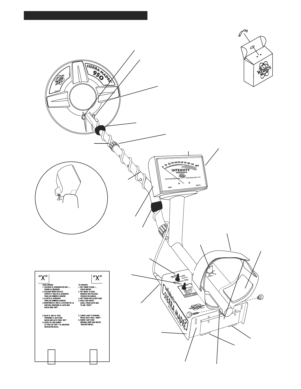
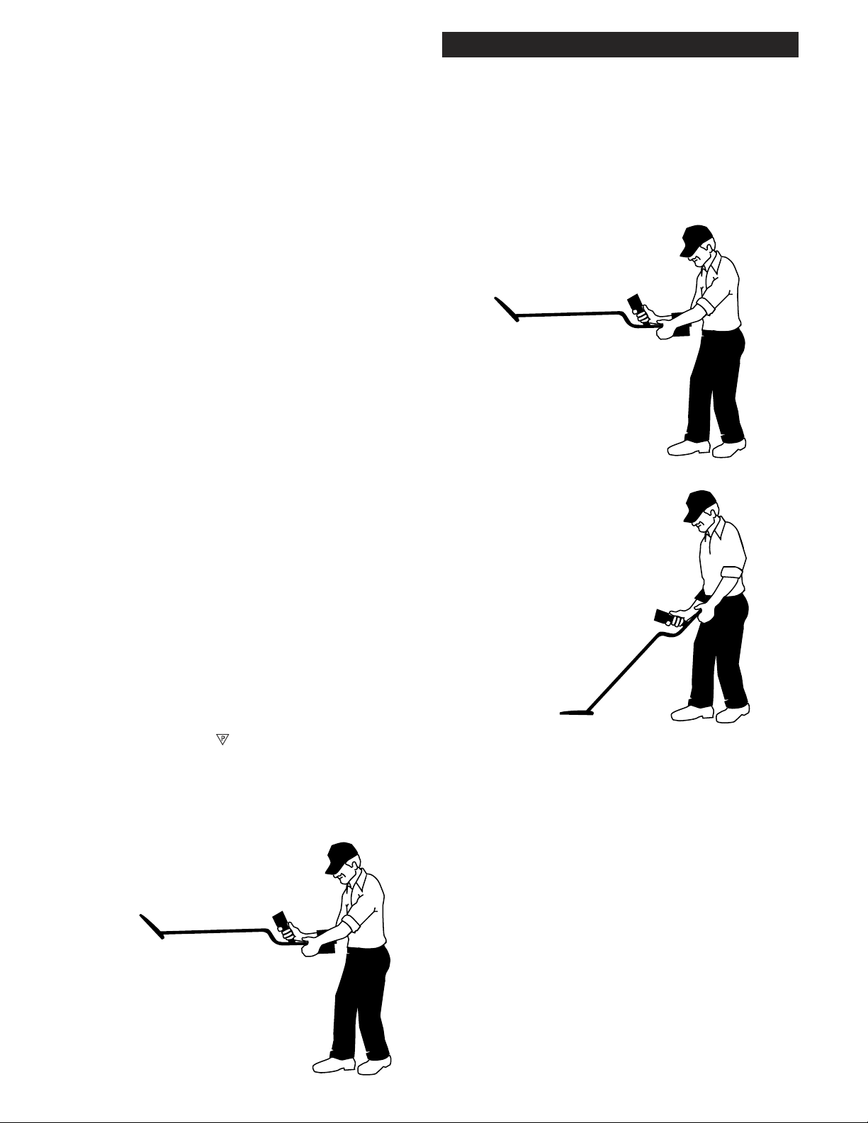
Assembly
Assembly
CLEVIS
LOWER
ROD
WASHERS
BETWEEN
EACH LOOP
EAR & CLEVIS
LOOP OR SEARCH
COIL
CABLE RETAINER
CAMLOCK
TRIGGER
(behind display)
Twist and insert each end of
handle (provided) through
top of shipping carton into
second flap.
(CARRY CARTON)
METER - INDICATES
TARGET INTENSITY
LOOP CABLE
1. Center (Primary search)
2. Squeezed & held (Pinpoint)
3. Forward (Pinpoint lock)
Remove decal paper from the two rubber bumpers. Install on the bottom of the
control box, one in each of the front corners
(shown below by "X"). Press in place and
hold firmly for a few seconds then release.
“S” ROD
AUTO
GEB
CABLE
RETAINER
MODE
LOOP
CONNECTOR
TUNER
ELBOW
CUP
STRAP
ELBOW CUP
FOAM PADS
INSIDE ELBOW
CUP
2
CONTROL BOX
BOTTOM OF
CONTROL BOX
BATTERY
COMPARTMENT
DOOR
BATTERY
COMPARTMENT
LATCHES
HEADPHONE
JACK
Page 3

Assembly Instructions
1. Remove all parts from shipping carton and
check the assembly page to make sure all parts are
present.
Assembly
readjust clevis/lower rod length with the spring clip
buttons so that the search coil can be held near the
floor without requiring stooping over.
2. Insert rubber washers between clevis/lower rod
and loop ears. Use only nonmetallic washers,
fiber bolt, and thumbnut to secure loop/search
coil to clevis/lower rod.
3. Unlock "S" rod camlock and insert clevis/lower rod into curved "S" rod so that stainless steel
spring clip buttons line up and lock into one of
the adjustment holes in the curved "S" rod. Turn
camlock to secure. The second or third adjustment
holes are suitable for average size adults. Individuals 6' or taller should use the fully extended position. Individuals well over 6' tall should purchase
the optional Tall Man Rod.
4. Unravel loop cable and wind the cable around
the clevis and rod assembly, first revolution over
the top of the rod. Wind cable all the way to the
top of the curved "S" rod, about five revolutions.
Use the black cable retainers, one near the loop,
and one near the top of the curved "S" rod, to hold
the loop cable in place.
5. Unlock control box rod camlock and insert
curved "S" rod so that stainless steel spring clip
buttons line up and lock into the rod on top of the
control box. The "S" rod is designed to curve up
toward the display. However, those who prefer to
sweep the loop close to their feet may desire to
assemble the "S" rod to curve down toward the
ground. Turn camlock to secure. Plug loop connector into control box, screw lock ring to secure.
7. Remove the protective paper from the two black
elbow cup foam pads. Carefully align pads on the
inside of the elbow cup, one on each side of the
center rod, and press firmly into place.
8. Adjust the elbow cup strap so that it is loose
enough for you to slide your arm in and out without loosening each time you want to set the detector down. The elbow cup strap provides extra
leverage and control. However, some prefer not to
use it.
9. Install battery as described in the next section,
decal facing down, with plastic tab and steel con-
tacts facing toward inside of battery compartment.
10. It should be noted at this point that the detector
may not work as expected indoors due to the high
degree of metals used in modern construction. It
is best to tune and practice out-of-doors to ensure
stable, predictable results. Additionally, freshlyburied targets will not produce the normal depth
results of targets that have been naturally lost
and settled in the ground. Due to the abnormality
caused by digging a hole in the ground matrix, and
the sophistication of the ground rejection circuitry,
it may take a number of years for freshly-buried
targets to respond at true depths and accuracy. The
best way to determine true detection depth is in
real search conditions.
6. Grip the instrument by the handle, with your arm
in the elbow cup with strap secure, and sweep the
loop/search coil over the floor. If the instrument fit feels
uncomfortable, adjust the elbow cup by removing and
repositioning the bolt/thumbnut and installing in one of
the optional positions. If necessary,
3
Page 4
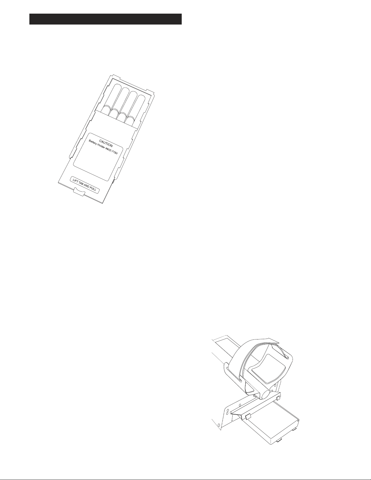
Batteries
Batteries
Using the
Standard Battery Holder
1. Slide open the battery holder lid (decal side of
battery holder) by applying gentle upward
pressure on the tab of the door so that it unlocks.
Slide the door away from the battery box
exposing the cell positions.
2. Remove any old cells from the holder. Note the
(+) and (-) positions of each cell and the (+)
and (-) for each position marked inside the cell
tray. Install new “AA” cells noting carefully the
correct (+) and (-) positions.
Standard Battery Holder
1. The standard battery holder holds eight “AA”
cell batteries equalling 12 volts total. Alkalines
are recommended for use with this model. During
normal searching conditions you can expect about
16 hours of hunting time from a quality set of eight
alkaline batteries.
2. Non-alkaline batteries can be used in this holder.
When non-alkalines or rechargeable “AA”
cells are used, detecting time (before replacement/
recharge) may be reduced to about 10-12 hours.
3. The battery voltage appears automatically on
the meter when the Tuner knob is used to turn the
Sierra Madre "ON". Once the batteries become
weak (8 volts) , upon turning the Tuner knob ON,
the meter will indicate to the left of the Batt Good
range
If the cells are installed incorrectly, the detector
may require service by an Authorized
Service Center.
3. Slide the door closed so that it snaps securely.
4. Insert the battery holder into the detector so that
the decal is facing down, with the battery
holder door tab and metal contact points facing
toward the inside of the battery compartment.
Close the battery compartment door and secure
the two latches on the bottom of the case. Hook
the front of each latch first, then press down on the
rear.
4. The battery compartment opens by gently pulling down on the front of each of the two latches (on
the bottom of the control box) releasing the catch
and hinging open the door.
4
Page 5
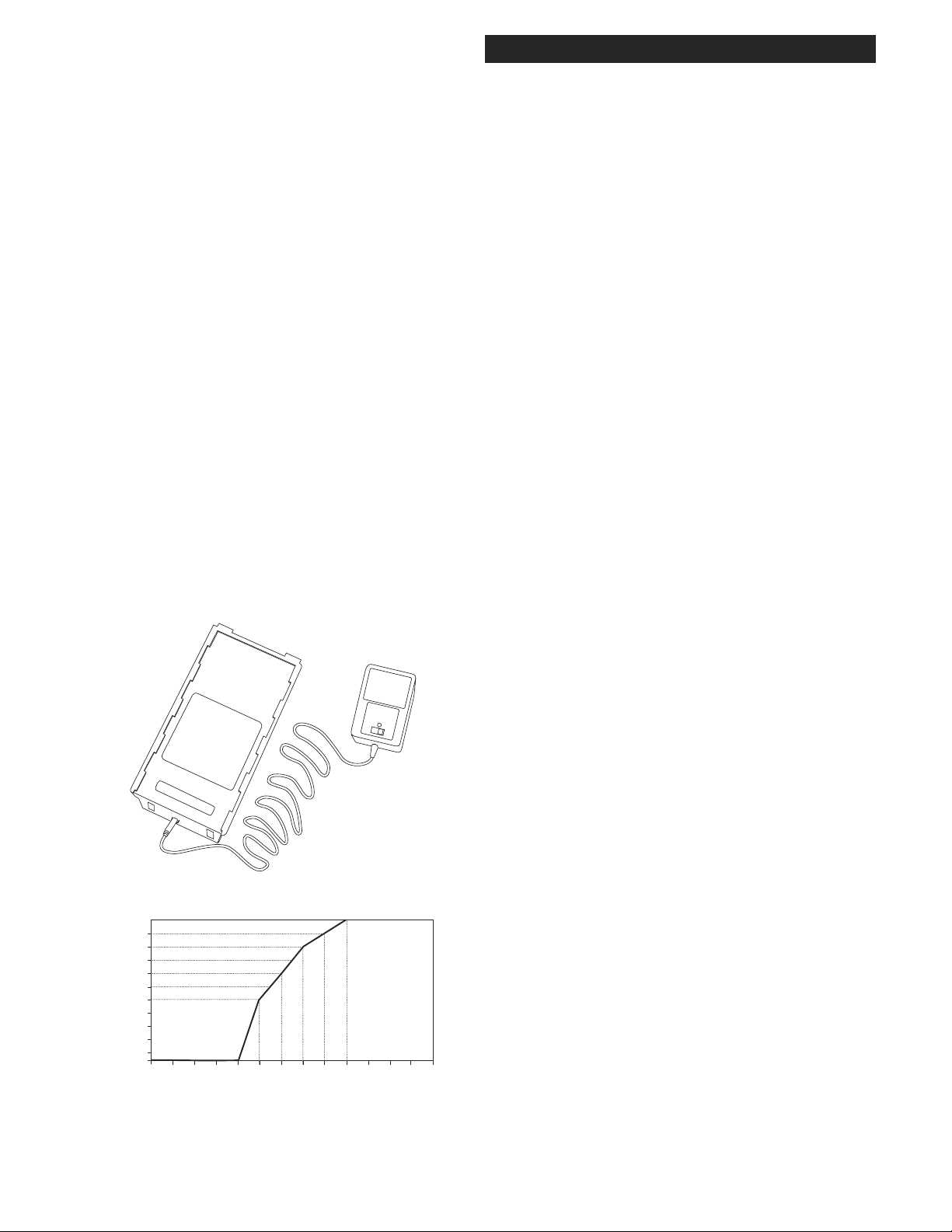
Rechargeable Battery (Opt.)
CAUTIO
N
Battery #802-521
1
13 12 11.5 11 10.5 10 9.5 9 8.5 8 7.5 7 6.5 6
5
4.5
4
3
2.5
2
1.5
1
0.5
0
3.5
Any voltage reading
less than 8 voltscharge for 5 hours
maximum on
Quick Charge
setting. Further
charging can
damage the
system.
Do not charge until
voltage reading drops
below 10.5 volts.
Charging
Hours
Using the Battery Charger on Quick Charge Setting
Battery Voltage Reading
A rechargeable battery system is not standard equipment, however, high quality systems are available.
White's rechargeable battery #802-5211, and charger #509-0022 are recommended and offer quick
charge and overnight charge options.
Batteries
Non-rechargeable batteries will start to drop in
voltage as soon as they are put into use and then
steadily diminish in voltage till they die. The Nicad
rechargeable battery pack, however, will diminish
very slowly (plateau) in somewhat of a flat line and
then drop like a rock.
Rechargeable batteries deliver fairly constant voltage until they're nearly dead. If you use them until
they are dead, they will deteriorate more quickly
than if you only use them until their voltage starts
to drop significantly. Rechargeables should be taken
out of service and recharged as soon as you notice
battery check to the left of the Batt Good range
on the meter upon turning Tuner ON. Rechargeable
batteries will not provide the same amount of continuous use as a new set of Alkaline batteries.
Headphone use prolongs all battery life.
Battery life will vary a great deal with temperature,
number of target signals, battery type, brand, and
shelf life.
5
Page 6
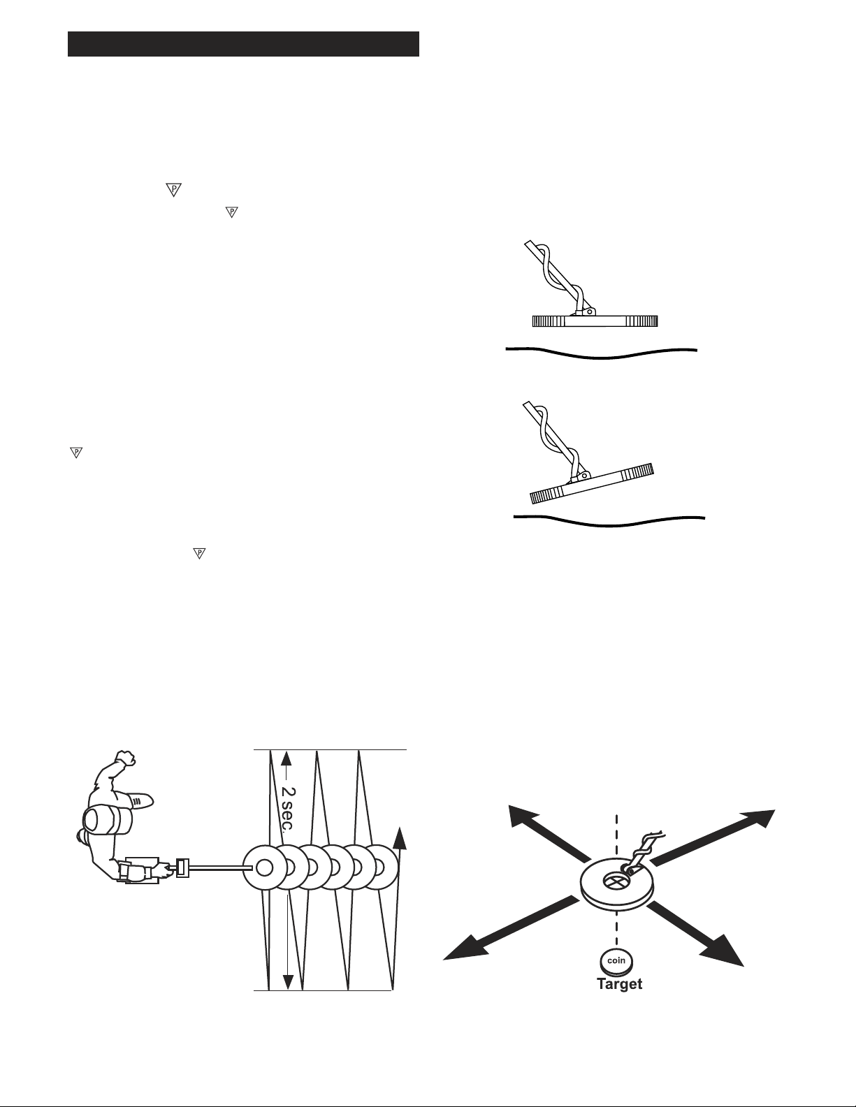
Tuning and General Use
Wrong
Righ
t
Right
Tuning and General Use
Preset:
Placing the TUNER to (Preset). AUTO GEB
(automatic ground exclusion balance) to GND
AUTO TRAC (ground automatic tracking), and the
MODE to the HIGH, good results will be achieved
in average conditions. However, it may be necessary to fine tune the detector for use in other than
average ground, or simply to maximize performance for a specific type of searching. These preset
positions are intended to offer generally acceptable
settings. Most anxious detectorists prefer to venture
out and use their new detector for the first time
before they have carefully read this manual. The
allows such use with surprising success. After
use, the SIERRA MADRE will eventually fine
tune its own ground rejection through tracking,
thus improve its performance automatically. It has
also been found that becoming proficient using
the detector at the settings eases the learning
curve, making further study a smoother and more
enjoyable experience.
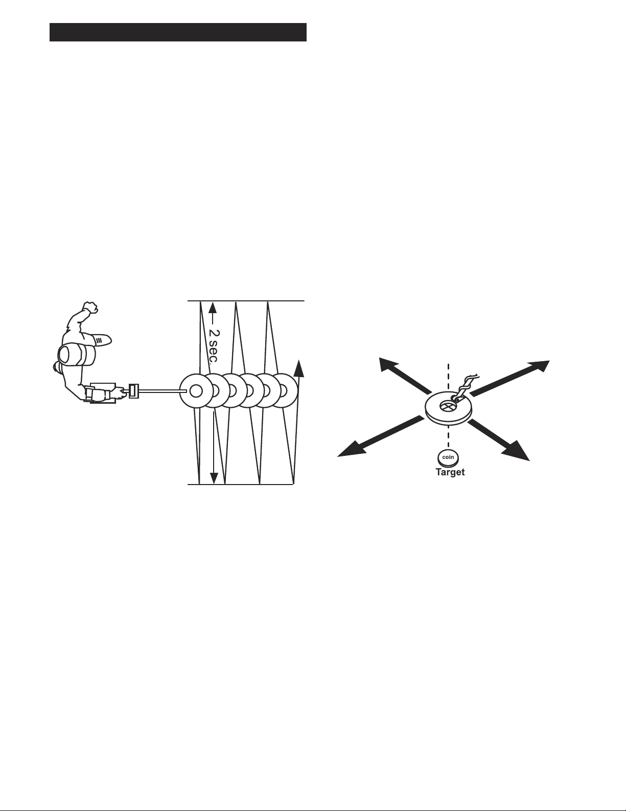
Keep the loop sweeping from side to side very
close to the ground, always moving. Those using
a detector for the first time often sweep the loop
too slowly; a brisk sweep of about two seconds for
each pass is desirable.
Keep loop flat to the ground.
Metals produce a solid abrupt “beep”. The meter
deflects positive (to the right) in unison with the
sound “beep”. Sweep the loop over the area several
times. Once the decision has been made to dig,
slowly “X” the loop over the area to pinpoint
its exact location. The strongest sound and furthest
meter movement to the right
indicate target center.
Overlap each pass by at least 50%.
6
Page 7
Tuning and General Use
Fine Tuning:
Fine tuning the SIERRA MADRE immediately
improves performance. The keys to fine tuning are
the AUTO GEB switch and the MODE control.
The AUTO GEB (automatic ground exclusion
balance) switch sets the ground rejection. When
the ground is rejected the detector can see deeper
targets, and less susceptible to ground interference.
The MODE control is used to regulate the amount
of ground signal the detectorʼs electronic circuitry
can handle. The HIGH setting allows for typical
high mineral ground. There are some rare areas of
low ground minerals. These areas are best searched
with the MODE control set to LOW. If you are
unfamiliar with ground mineralization always
start with the HIGH setting, reserving the LOW
setting for a time when you have more experience.
Each time the MODE control is changed to a
different position it is best to squeeze and release
the TRIGGER on the handle with the loop at waist
level.
3. Push the AUTO GEB switch to the AIR
position and hold it there until the detector beeps.
Immediately lower the loop to the ground and pull
the AUTO GEB switch to the GND AUTO TRAC
position (ground auto tracking). Hold the loop
steady until the detector again beeps.
When a new area is to be searched, the following
steps should be followed to maximize performance.
When changing to another area, or when dramatic
changes in the ground are visible, these steps
should be repeated.
Fine Tuning Steps:
1. Set the TUNER to , and look at the meter
to assure the batteries test good. Hold the loop at
waist level and adjust the TUNER for a slight hum.
2. Set MODE to HIGH, squeeze and release the
TRIGGER on the handle.
4. If the ground is low in mineralization (rare)
you may want to set the MODE to the LOW
position, squeeze and release the TRIGGER on
the handle and repeat step 3 (AUTO GEB). If
you were mistaken about the ground being low
in mineralization, the detector will respond to the
ground (false signal) and otherwise act unstable
and unpredictable. If this occurs you should switch
back to the HIGH position, squeeze and release
the TRIGGER on the handle, and repeat step 3
(AUTO GEB). You can then resume searching. If
the SIERRA MADRE works smooth, stable, and
predictably at the LOW setting, then continue to use
the LOW position in that type of ground.
7
Page 8
Tuning and General Use
Fine Tuning & General Use,
Continued
5. As searching begins, the sweep of the loop plays
a critical role in how well the detector works.
Sweep the loop close to the ground, from side to
side, overlapping each pass. One pass from left to
right should take one and a half to two seconds.
Moving from right back to left, where the sweep
first started, should take another one and a half to
two seconds. The maximum detection depth will be
in the center of the loop, thus if loop passes are not
overlapped by at least 50%, some deep targets may
be missed. Do not arc the sweep at each end. Keep
the loop close to the ground throughout the sweep.
a digging tool, contact your dealer. The type of
digging tool best for your area, your type of
searching, and best for you personally, is a matter
of opinion. The important thing to remember
is consideration. Fill in all holes you dig. Be
thoughtful regarding where and when you dig.
Obviously midday on a beach crowded with
sun bathers, is not a good place to search. Early
morning or late evening is more appropriate. If
someone cares for a lawn (keeps it looking nice)
and yet gives you permission to search, be equally
thoughtful by taking extra steps to minimize any
damage digging may do to the vegetation. The
use of a small drop cloth (to place dug soil onto)
is suggested in such areas. This minimizes soil
smearing around the hole, making such diggings
less noticeable
Center of Maximum Signal
equals
Center of Target.
6. Once a solid abrupt "beep" is heard, (indicating a
metal), sweep the loop over the areas several times
so as to roughly find the center. Consult the meter
indication which will indicate the furthest positive
(to the right) when the loop is directly over the metals center. Further pinpointing assistance may be
achieved by squeezing and holding the TRIGGER
on the handle. Squeeze and hold the TRIGGER on
the handle, and "X" the loop over the area. Note the
loudest sound and furthest meter movement to the
right. This pinpoints the metals precise location and
by sweeping the loop over the general area gives
some idea as to its size and shape. Shallow targets
may be difficult to pinpoint. Lifting the loop a few
inches higher and again sweeping over the area will
improve accuracy in such cases.
7. Pinpointing and digging take some time and
practice. Many different types of digging tools
are available to help you. If you donʼt yet have
8
8. A location to search, and getting permission, is a
major part of a successful metal detecting. Research
always pays off. It may mean digging through old
newspapers at the local library, documents at city
hall, or just talking to a lot of longtime citizens.
You will be surprised what you can find out, and
research can be half the fun! Do not be discouraged
if someone has already searched an area even with
multiple searches. Take a little more time and dig a
few more targets. Often areas replenish themselves
either through use, such as a beach where jewelry
is continually lost, or through naturally occurring
shifts in the soil, frost heave, erosion, etc., which
bring previously undetected targets within reach.
Sand and soil movement in many areas makes each
season a new ball game.
Page 9

Explanation of Controls
Explanation of Controls
1. TUNER: The TUNER control turns the instrument ON/OFF, tests the battery strength
(BAT.√), and selects the steady hum or threshold
which should be heard continually during use.
The TUNER should be set to a slight steady hum
(threshold) each time the instrument is to be operated. Changes in temperature will change the
particular area of the control needed to achieve a
threshold hum.
A. OFF position is selected when the detector is
not in use. (Batteries should be removed when
the detector is stored.)
B. BAT. CHK. Battery Check is used to check
the condition of the batteries. When placed in this
position, the current battery condition is shown
on the meter. An indication anywhere in the
BATTERY GOOD area will operate the detector. Once the battery no longer indicates in the
BATTERY GOOD area, new batteries should be
installed. Usually batteries last between eight and
16 hours of use. (Battery life varies with type,
temperature, and mode). The use of headphones
will significantly improve battery life.
A. HIGH MINERAL, is the primary MODE
used for general searching. It minimizes common high mineral ground effects (large ground
signal). High ground mineralization typically
will cause more receive signal than the electronic circuitry can handle. Such conditions result in
overload of the receiver, which will cause poor
detection depth. The HIGH setting compensates
for such ground conditions.
B. LOW MINERAL is used in those rare
areas that have little or no mineralization. It
maximizes performance in such low mineral
ground(minimal ground signal). Low ground
mineralization typically has little or no effect
on the receive signal, the LOW setting compensates for this lack of ground signal thus
improving performance in such ground types.
CAUTION: If the LOW setting is used in high
ground mineralization the detector will become
unstable and unpredictable. Switching back to
the HIGH setting, squeezing and releasing the
TRIGGER on the handle, and repeating the
AUTO GEB sequence will regain the stability
necessary for good detection results.
C. To set the TUNER hold the loop at waist
level away from metal and the ground, turn the
TUNER control until a very slight faint hum
(threshold) is heard. The TUNER control should
end up near .
D. Silent Search once the threshold has been
set, the TUNER can be turned very slightly toward (-) to produce silent searching until a target is detected. Doing so, some detection depth
may be lost.
2. MODE: The MODE control selects either
HIGH (MINERAL) or LOW (MINERAL)
ground. Special attention must be used when
changing MODEs. Each time the MODE is
changed the TRIGGER on the handle should be
squeezed and released.
3. AUTO GEB: The AUTO GEB switch is used
to select the actual ground selection setting, so
that ground minerals can be ignored. When
ground minerals are ignored, increased detection depth and smoother operating stability are
achieved. The AUTO GEB also selects whether
the ground rejection setting stays as originally
set ( LOCK), or whether the instrument automatically updates this original setting to accommodate naturally occurring changes in the
soils mineralization, (AUTO TRAC). Setting the
AUTO GEB is recommended each time you use
your instrument.
A. To set the AUTO GEB place MODE to
HIGH, squeeze and release TRIGGER on handle. Hold the loop at waist level away from all
types of metals and ground minerals and adjust
the TUNER for a slight background hum. Press
9
Page 10

Explanation of Controls
Explanation of Controls, Continued
the AUTO GEB switch to the air position and
hold it there until a “beep” is heard. Immediately lower the loop to the ground to be searched
and pull the AUTO GEB switch down to the
GND AUTO TRAC position. Hold the loop
steady until another “beep” is heard.
B. GND AUTO TRAC is recommended for
most searching conditions as it automatically
tracks (adjusts) to any changes in the ground.
This continual updating of the ground rejection
setting improves performance.
C. LOCK may be desired in areas which
contain a lot of man-made decomposed iron,
such as rusty iron which will tend to trick the
AUTO TRAC feature (recognizing it as a
mineral rather than a metal).
4. TRIGGER SWITCH: The TRIGGER switch
located on the handle is used for several different purposes. The TRIGGER has three possible
positions; “center” which is used for normal
searching, “squeezed and held” which activates a
temporary change in the mode, and “locked forward” which is the same as squeezing and holding except mode change is locked in.
TRIGGER or pushing it forward locking it in
place will temporarily activate the all-metal non
motion mode. This is ideal for pinpointing as
the search mode requires some movement of the
loop to respond to metal targets, making
pinpointing difficult for some individuals. Holding the TRIGGER disengages the stabilizing
motion feature. This mode can only be accessed
by squeezing and holding the TRIGGER or
pushing it forward to lock. Because it lacks the
stability of the standard search mode it is not
recommended to continually search with this
mode accessed. The standard search mode is designed for general searching. This pinpoint
mode is best reserved for pinpointing. Releasing the TRIGGER returns the instrument to the
original mode.
A. Reset, clear, or retune after control adjustments or pinpointing. Most control adjustments
will cause sections of the electronic circuitry to
become out of sequence. Squeezing and releasing the TRIGGER will reset or clear so that all
the electronic circuitry works in unison. Manual
pinpointing (when the TRIGGER is squeezed
and released while the loop is near a metal)
will narrow the loopʼs detection field. This is
called detuning. The loopʼs detection field will
remain narrow until the TRIGGER is squeezed
and released (while holding the loop away from
any metal). This resets the loopʼs detection field
allowing it to detect its widest possible search
pattern.
B. Changes Mode Squeezing and holding the
10
Page 11

Explanation of Controls
Explanation of Controls, Continued
The Meter:
The Meter is used to test the battery strength, and provides a visual indication of a metal by detecting
positively (to the right). The meter and the sound "beep" work simultaneously to provide an indication of
metal.
Fifteen Inch Loop:
The optional (accessory) fifteen inch loop increases detection depth regarding physically large targets. Little or no increase in detection depth may be noted on small (coin sized) targets. The increase in detection
depth applies only to physically large metal items, or a large group of small targets (jar of coins). Tuning
and use of the fifteen inch loop is identical to use of the smaller loop size. Sweeping the loop a little slower
is suggested when the larger loop is used. If you have trouble with the added weight of the fifteen inch
loop you may consider Whiteʼs Hipmount Conversion Kit, or contact your Dealer for other handle support
options.
Headphones:
The optional (accessory) headphones are recommended for use with the Sierra Madre. Headphones will
increase battery life, reduce distractions, and allow better hearing of the signals produced by metals, Most
often headphones have separate volume controls for each ear, and a stereo/mono switch. Check that each is
in the correct position so that sound is heard from both ears.
11
Page 12

Trouble Shooting
Trouble Shooting
When trouble occurs with the use of a metal detector,
often a person can avoid unnecessary inconvenience by
reviewing the following tips.
1. False Signals or Instability can often be caused by
situations outside of the detector. For example electrical interference from power lines, or other high power
transmitting devices. Often these devices can be identified, sometimes they can not.
A. Try the HIGH MINERAL MODE setting,
squeeze and release the TRIGGER and repeat the
AUTO GEB sequence.
B. Persistent false signals may require that you
try searching a different area, at least several miles
away. If you really want to search a high interference area, try different times of the day or week.
Often such interference is only present at scheduled
times.
C. If not area related, start checking the components of the detector. The battery pack should
be removed from the instrument and the contacts
inside the battery holder should be scratched clean
of any corrosion buildup, and the springs should
be stretched a little to assure a firm contact. The
contacts on the outside of the battery holder should
also be scratched clean of any corrosion. The battery contacts inside the instrument battery compartment should be pulled slightly outward toward the
battery door so that they make a firm contact with
the battery. The instrument control box should be
checked with a different loop, either an accessory,
or a friendʼs loop off a similar model. Your Dealer
may also be able to assist you in checking the
instrument. Loop problems are most often due to
damaged cable, from snags on brush or blackberry
vines, or simple cable wear. Inspect the cable for
any visible signs of damage.
2. Moisture and Humidity, when extreme, can cause
problems with all electrical circuits. Most electronics
are only guaranteed to operate in up to 75% humidity,
which is minimal humidity in some areas. Although the
electrical circuitry of your instrument has been sealed
with a plastic coating, wetness can still cause failure,
particularly when the dampness is combined with salt,
as occurs in many beach environments.
to dry out when not in use. Remove the batteries
and leave the battery door open.
B. Dampness Failure can often be cured simply
by drying the instrument out in the above manner. Dampness failure can cause varied symptoms,
everything from complete non-responsiveness to
instability or false-targeting.
3. Meter Indications can be affected by static electric-
ity. This static can get on the meter face and housing
and cause improper meter indications, inaccuracy, and
even total lock-up of the meter needle. Such static electricity usually comes from household or automobile
carpet, or clothing. When passing your finger past the
meter needle causes significant meter movement, static
electricity is the problem.
A. Meter Failure should be remedied by discharging any electrical field built up in the meter housing and meter face cover. Anti-static clothes dryer
sheets work well for this purpose, and can be purchased inexpensively from the grocery store. Computer stores have an antistatic spray which also
works well. With the clothes dryer sheets simply
wipe the black meter housing and meter face cover
thoroughly. Use several of the individual sheets.
With the antistatic spray, spray the meter housing
and face cover, wipe dry with a cotton cloth.
B. Once Static is Removed the meter should return to normal. Removing meter static electricity
may be necessary from time to time.
4. Repairs in the unlikely event your instrument
requires servicing, it should be referred to a trained
professional at an Authorized Whiteʼs Service Center. Todayʼs models require specialized equipment
and training to service properly. All Whiteʼs Authorized Service Centers have years of experience and
their work is guaranteed by the factory.
5. The Location of the Whiteʼs Authorized Service
Center for your area is enclosed (see page 14). If misplaced, telephone toll free 1-800-547-6911 for their
name and address. Please send the complete unit with
an explanation of the trouble.
A. Damp Environment Use should always be followed by placing the detector in a warm dry place
12
Page 13

Caring For Your Instrument
Caring For Your Instrument
Precautions:
1. Water can damage your instrument. The loop is
waterproof and submersible, however the loop-tocontrol box connector and the control box itself are
not waterproof. Light rain or drizzle will not cause
a problem. However, the control box must be protected from heavy rain or submersion in water.
A. The loop can be cleaned with a mild soap
and water. A damp cloth can be used to wipe
clean the control box. The control box can be
polished with automotive or furniture wax. Use
only cotton cloth to clean and wax. The instrument should be cleaned after heavy use in or
around a saltwater beach. Salt is very corrosive.
(The warranty does not cover cosmetic imperfections due to wear, or exposure to sun and
salt.)
B. When searching with the loop in the water or
wading, be careful. The rod will fill with water,
and if lifted above the height of the control box,
will run into the rod on top of the control box.
Although sealed, some seepage can occur into
and on top of the circuitry, causing malfunction.
Again, drying the detector in a warm area with
battery removed and compartment open will
most often cure any malfunction. If for any reason the control box is dunked in saltwater, flush
the entire instrument with fresh water immediately prior to letting the detector dry out.
3. Heat and Cold can have an adverse effect on
your detector. When not searching, rest your detector in the shade. When left in a car on a hot day,
cover it to protect it from the direct sun. Extreme
sub-zero temperatures can also cause problems.
Store your detector indoors in a heated area during
the winter months, with the batteries removed and
from the battery holder.
4. Common Sense should be used. Avoid impacts,
stacking heavy objects on top, and unnecessary
roughhousing. When not in use, the detector should
be treated like any other sophisticated electronic
device.
2. Loop Covers, a protective plastic shield for the
loop bottom, are highly advised accessories when
searching sand or rocky terrain on a regular basis.
They are available from Dealers and have no effect
on detection depth. Loop covers should be removed
periodically to remove any sand which can affect
detector performance.
13
Page 14

Service
1
2
3
Factory Authorized Service Centers
At your nearest White's Service Center, everything is carried out just as if you returned your metal detector
to our factory in Oregon. White's Service Centers are factory trained and equipped, and provide high levels
of metal detector service with fast turn-around times. Constant communication with the factory keeps them
up-to-date with the latest manufacturing and technological details. Your area service center offers many
advantages. We encourage you to take advantage of the local option, and use them for all of your White's
service needs.
1. White's West Service Center
Whiteʼs Electronics, Inc.
1011 Pleasant Valley Road
Sweet Home, Oregon 97386
Telephone: 1-541-367-6121
Fax: 1-541-367-6629
service@whiteselectronics.com
2. White's Midwest Service Center
Electronic Exploration
575 West Harrison
Lombard, Illinois 60148
Toll Free: 1-800-392-3223
630-620-1005
E-Mail: tony@ee-il.com
3. White's Southeast Service Center
Centerville Electronics
10063 Wellington Rd.
Manassas, Virginia 20110
Toll Free 1-888-645-0202
(703) 367-7999
Fax: 1-703-367-0868
E-Mail: centelec@vwx.com
Before shipping detectors for service:
A. Contact your Dealer. There may be a quick,
simple fix or explanation that will prevent
having to send the detector in for service.
B. Double check the obvious, such as batteries,
and try the detector in another area to be sure
there is not interference.
C. Be sure to send all necessary parts with your
detector, such as search coil, batteries and
holders, as these items can result in symptoms.
D. Always include a letter of explanation about
your concerns, even if you have talked to the
Service Center by telephone.
E. Take care in packaging instruments for
shipping and always insure your package
14
Page 15

White's Electronics, Inc.
Limited Warranty
Warranty
If within two years (24 months) from the original
date of purchase, your White's detector fails due to
defects in either material or workmanship, White's
will repair or replace at its option, all necessary
parts without charge for parts or labor.
Simply return the complete detector to the
Dealer where you purchased it, or to your nearest
Authorized Service Center. The unit must be
accompanied by a detailed explanation of the
symptoms of the failure. You must provide proof of
date-of-purchase before the unit is serviced.
This is a transferable manufacturer warranty, which
covers the instrument two years from the original
purchase date, regardless of the owner.
Items excluded from the warranty are nonrechargeable batteries, accessories that are not
standard equipment, shipping / handling costs
outside the continental USA, Special Delivery
costs (Air Freight, Next Day, 2nd Day, Packaging
Services, etc.) and all shipping / handling costs
inside the continental USA 90 days after purchase.
White's registers your purchase only if the Sales
Registration Card is filled out and returned to
the factory address by your dealer, soon after
original purchase for the purpose of recording this
information, and keeping you up-to-date regarding
White's ongoing research & development.
The warranty does not cover damage caused
by accident, misuse, neglect, alterations,
modifications, unauthorized service, or prolonged
exposure to corrosive compounds, including salt.
Duration of any implied warranty
(e.g., merchantability and fitness for a particular
purpose) shall not be longer than the stated
warranty. Neither the manufacturer or the retailer
shall be liable for any incidental or consequential
damages. Some states however, do not allow the
limitation on the length of implied warranties, or the
exclusion of incidental or consequential damages.
Therefore, the above limitations may not apply to
you.
In addition, the stated warranty gives you specific
legal rights, and you may have other rights which
vary from state-to-state.
The foregoing is the only warranty provided by
White's as the manufacturer of your metal detector.
Any "extended warranty" period beyond two years,
which may be provided by a Dealer or other third
party on your detector, may be without White's
authority involvement and consent, and might not
be honored by Whiteʼs Electronics, Inc.
15
Page 16

Warranty Transfer
White’s Electronics, Inc.
Warranty Transfer
If for any reason you should sell your White's metal detector prior to the date the warranty
expires, the remaining warranty is transferable. This transfer is authorized by calling
1-800-547-6911, and getting an Authorization Number.
Simply fill out the following information, including the Authorization Number, seal it in a
stamped envelope, and send it to White's Electronics, 1011 Pleasant Valley Road, Sweet
Home, Oregon 97386. The remaining warranty period will then be available to the new
owner.
The Warranty Statement applies to both the original owner as well as the second owner.
"
Original Owner:
Name: __________________________________________________________
Address (Which appears on the original warranty card):
________________________________________________________________
________________________________________________________________
Instrument Serial Number: __________________________________________
Original Purchase Date:_____________________________________________
New Owner:
Name: __________________________________________________________
Address: ________________________________________________________
________________________________________________________________
________________________________________________________________
Comments: ______________________________________________________
________________________________________________________________
________________________________________________________________
________________________________________________________________
________________________________________________________________
WARRANTY TRANSFER
®
16
Distributor Authorization Code: _______________________________________________
P/N 621-0496 Printed In USA
Page 17

Indice
Indice del Sierra Madre
Identificación de Piezas y Montaje ................................................................................. 18-19
Baterías ........................................................................................................................... 20-21
Afinación y Uso General .................................................................................................22-24
La Explicación para Cada Control:
Afinador ......................................................................................................................... 24
Modo .......................................................................................................................... 24-25
GEB Auto ........................................................................................................................ 25-26
Gatillo ..� 26
Medidor � 27
Aro de Quince Pulgadas ....................................................................................................... 27
Audífonos ............................................................................................................................. 27
Búsqueda de Averías ............................................................................................................ 28
El Cuidado De Su Detector .................................................................................................. 29
Centros de Servicio .............................................................................................................. 30
Declaración de la Garantía ................................................................................................... 15
Transferencia de Garantía .................................................................................................... 31
Dirección/Numero de Teléfono del Fabricante ................................................ Contra Portada
17
Page 18

Montage
Montaje
CLAVIJA
BARRA
INFERIOR
ARANDELAS
ENTRE CADA
ALETA DEL
ARO Y CLAVIJA
ARO O PLATILLO DE
BUSQUEDA
SOSTEN DEL CABLE
SUGUROS CAMLOCK
EL GATILLO
(detrás de la pantalla)
Déle vuelta (tuerce) e
inserte cada extremo de
la manija (incluido) por la
parte superior del empaque
de envió y adentro de la
segunda aleta.
(ESTUCHE PARA CARGAR)
EL MEDIDOR - INDICA
LA INTENSIDAD DE
OBJETIVO
CABLE DEL
ARO
1. Centro (Búsqueda Primaria)
2. Presionado y sostenido
(Localización Exacta o “Pinpoint”)
Hacia Adelante (fijado para
localización exacta o “Pinpoint”)
Remueve el papel de etiqueta de los dos
retenedores de hule. Instálalos en la parte
inferior de la caja de control, uno en cada
uno de las esquinas de enfrente
(que se muestran abajo con la “X”).
BARRA “S”
DE AUTO
GEB
SOSTEN
DEL
CABLE
MODO
CONEXION
DEL
ARO
TAZA DEL
CODO
TUNER (AFINADOR)
CORREA DE
LA TAZA
DEL CODO
COJINES DE
HULE
ESPUMA
18
CAJA DE
CONTROL
PARTE
INFERIOR
DE LA CAJA DE
CONTROL
PUERTA DEL
COMPARTIMIENTO
DE LA BATERIA
CIERRES DEL
COMPARTIMIENTO
DE LA BATERIA
CONEXION DE
AUDIFONOS
Page 19

Instrucciones para el
Montaje
1. Remueve todas las piezas del empaque de envió y revise
la pagina de montaje para asegurar que cada pieza este
presente.
2. Coloca las arandelas de hule entre la clavija/barra inferior
y las aletas del aro. Solo use arandelas no-metálicos, tornillo
y tuerca de mano hechos de fibra para asegurar el aro/platillo
de búsqueda a la clavija/barra inferior.
3. Abra el seguro “camlock” de la barra “S” y coloca la
clavija/barra inferior en la barra “S” de manera que se
alineen los botones de resorte de acero y se encajen en una
de las aberturas de ajuste de la barra “S”. Déle vuelta al
seguro “camlock” para fijarlo. Las aberturas de ajuste del
segundo o tercer nivel son adecuados para un adulto de
tamaño ordinario. Los individuos que miden 6 pies o mas
de estatura deben usar la posición de totalmente extendida.
Los individuos quienes miden mucho más que 6 pies deben
comprar la barra opcional Hombre Alto (Tall Man Rod).
4. Desenreda el cable del aro y enróllelo alrededor de la
asamblea de la clavija y la barra, la primera vuelta va por
encima de la barra. Envuelva el cable por completo hasta la
parte superior de la barra “S”, debe ser como cinco vueltas.
Use los retenedores de cable negros, uno cerca del aro, y uno
cerca de la parte superior de la barra “S”, para sostener el
cable del aro en su lugar.
5. Abra el seguro “camlock” de la barra de la caja de control
y coloca la barra “S” de manera que se alineen los botones
de resorte de acero y se encajen en la barra encima de la
caja de control. La barra “S” esta diseñada para curvar arriba
hacia la pantalla. Aunque las personas quienes prefieren
rastrear el aro cerca de sus pies quizás deseen montar la
barra “S” de manera que corva abajo hacia el suelo. Déle
vuelta al seguro “camlock” para asegurarlo. Inserte la
conexión del aro en la caja de control. Déle vuelta y apriete
el anillo de seguro para fijarlo
Montaje
búsqueda cerca del suelo sin que usted tenga que doblar hacia
abajo.
7. Remueve el papel protector de los dos cojincillos negros
para la taza del codo. Alinee los cojincillos cuidadosamente
en el interior de la taza para el codo, uno en cada lado de la
barra central, y presione firmemente en su lugar
8. Ajuste la correa de la taza para el codo de manera que esté
suficientemente suelto para que usted pueda deslizar su brazo
para meterlo y sacarlo sin tener que aflojar la correa cada vez
que quiera soltar el detector. La correa de la taza para el codo
le proporciona más apalancamiento y control. Sin embargo,
algunos prefieren no usarlo.
9. Instale la batería como se describe en la siguiente
sección, la etiqueta hacia abajo, con la oreja de plástico y
los contactos de acero hacia dentro del compartimiento de la
batería.
10. Es ahora cuando se deberá tomar en cuenta que el
detector quizás no funcione como se espera adentro de
los edificios debido a la alta concentración de metales
que se usan en la construcción moderna. Es preferible
afinar y practicar afuera de los edificios para obtener
resultados estables y predecibles. Además, objetivos recién
enterrados no producirán los mismos resultados normales
de profundidad como los objetivos que han sido extraviados
y enterrados naturalmente. Esto se debe a la anormalidad
que es causada cuando se cave un hoyo en la tierra, y la alta
sofisticación del circuito de rechazo de suelo, puede tardar
varios años para que los objetivos recién enterrados den una
respuesta verdadera de identificación a la profundidad real. El
mejor método para determinar la verdadera profundidad de
detección será en condiciones de una búsqueda real.
6. Sostén el instrumento por el mango, con su brazo
colocado en la taza para el codo y la correa asegurada,
y barra el aro por encima del suelo. Si el instrumento le
queda incómodo, ajuste la taza para el codo quitando y
reacomodando el tornillo/tuerca de mano y colocándolo en
una de las posiciones opcionales. Si es necesario, reajuste
la posición de la clavija/barra inferior con los botones de
resorte de acero de manera que pueda sostener el aro de
19
Page 20

Baterías
Baterías
Utilizando el Sostén
Estándar de la Batería
1. Deslice la tapa del sostén de la batería (el lado del sostén
con la etiqueta) usa un poco de presión hacia arriba sobre la
aleta de la puerta para que se abra.
Desliza la puerta hacia la dirección opuesta de la caja de la
batería así dejando expuestas las posiciones de las células.
2. Remueve todas las células desgastadas del sostén.
Tome nota de las posiciones de (+) y (-) para cada célula
y el (+) y (-) para cada posición marcada por dentro del
sostén de las células. Instala nuevas células “AA” notando
cuidadosamente las posiciones correctas de (+) y (-). Si
se instalan incorrectamente las células el detector puede
llegar a necesitar servicio por una Agencia de Servicio
Autorizada.
El Sostén Estándar de
Batería
1. El sostén estándar de batería sostiene ocho baterías de
“AA” Igualando a 12 voltios en total. Se recomienda usar
Alcalinas con este modelo. Durante las condiciones de
una búsqueda normal contara con alrededor de 16 horas de
búsqueda con el uso de ocho baterías alcalinas de calidad.
2. Baterías No-alcalinas se pueden usar en este sostén.
Cuando se usan “AA” no-alcalinas o recargables, se puede
reducir el tiempo de búsqueda (antes del reemplazo/recargo) a
10-12 horas.
3. El medidor automáticamente le indica el voltaje de la
batería cuando se usa la perilla de Afinación (TUNER) para
prender el Sierra Madre. Una vez que se baja el cargo de las
baterías (8 voltios), cuando se prende el detector, el medidor
le indicara del lado izquierdo del rango de Batt Good
(Batería buena)
3. Cierra la puerta deslizándola de manera que quede
firmemente cerrada.
4. Coloca el sostén de batería adentro del detector de manera
que la etiqueta quede en posición hacia abajo, y la aleta de la
puerta del sostén de batería y los puntos de contacto de metal
queden hacia el interior del compartimiento de batería.
Cierra la puerta del compartimiento de la batería y asegure los
dos cierres en la parte inferior de la caja. Primero engancha
la parte de enfrente de cada cierre, luego presione la parte de
atrás hacia abajo.
4. Para abrir el compartimiento de la batería jale hacia abajo
por la parte de enfrente de los dos cierres (en la parte inferior
de la caja de control) así soltando el gancho y abriendo la
puerta.
20
Page 21

Batería Recargable
CAUTIO
N
Battery #802-521
1
13 12 11.5 11 10.5 10 9.5 9 8.5 8 7.5 7 6.5 6
5
4.5
4
3
2.5
2
1.5
1
0.5
0
3.5
Charging
Hours
Horas para Recargar Usando el Cargador de Baterías con la Opción
de Carga Rápida (Quick Charge)
No recargue hasta que
el voltaje baje a menos
de 10.5 voltios.
Cualquier voltaje
indicando menos
de 8 voltios, cargue
por un máximo de
5 horas al nivel de
Quick Charge
(Carga Rápida).Si
sigue cargando a
este nivel por mas
tiempo puede ocasionar daños en el
sistema.
Indicación de Voltaje de Batería
(Opcional.)
Un sistema de batería recargable no es parte del equipo
estándar, pero, hay sistemas de alta calidad disponibles. Se
recomienda la batería recargable de White’s #802-5211, y el
cargador #509-0022, ambos le ofrece las opciones de carga
rápida o carga a través de la noche.
Las baterías recargables dan un voltio básicamente constante
hasta que se baja casi por completo la carga. Si usa las baterías
hasta que queden completamente descargadas se deterioraran
mas rápido de lo que normalmente sucede si los usara solo
hasta que el voltaje se baje a un nivel levemente notable. Una
vez que el indicador de battery check (reviso de batería) esté
del lado izquierdo del rango de Batt Good (batería buena)
en el medidor al prender el detector debe dejar de usar las
baterías recargables para recargarlas de nuevo. Las baterías
recargables no le proveerán la misma cantidad de tiempo
de uso continuo como lo que le dará un juego de baterías
alcalinas nuevas.
Baterías
desminuyendo el voltaje hasta que se desgasten por completo.
El sistema de baterías recargable Nicad se debilitara muy
lentamente al principio de manera estable durante un tiempo
y luego bajara rápidamente al final de su carga. El uso de
audífonos prolongara la vida de todo tipo de batería. La
duración de una batería puede variar con la temperatura,
numero de señales de identificación de objetivo, tipo de
batería, marca, y el tiempo de almacenamiento antes de la
compra.
Comenzará a bajar el nivel de voltaje de las baterías norecargables una vez que comience a usarlos y seguirá
21
Page 22

Afinación y Uso General
Incorrecto
Correcto
Afinación y Uso General
Preestablecido:
Colocando el AFINADOR (TUNER) a Preestablecido
(Preset). AUTO GEB (balance de exclusión de suelo au-
tomático) a GND AUTO TRAC (rastreo automático del
suelo), y el MODO (MODE) hacia HIGH (ALTO), lograra
buenos resultados en las condiciones promedias. Aunque,
quizás sea necesario afinar el detector para el uso en suelos
que no sean ordinarios, o para maximizar funcionamiento para
un tipo de búsqueda especifica. Las posiciones preestablecidas
(preset) son para ofrecer configuraciones que generalmente
sean aceptables. La mayoría de los usuarios/ prospectores ansiosos prefieren salir a usar por primera vez su nuevo detector
antes de leer cuidadosamente este manual de instrucciones.
El permite tal uso con un éxito sorprendente. Después del
uso, el SIERRA MADRE eventualmente se ajusta al rechazo
de suelo por si solo a través de seguir el rastreo (tracking), y
así automáticamente mejora su propio funcionamiento. También se ha notado que al hacerse eficiente usando el detector
con las configuraciones e facilita la curva de aprendizaje,
así logrando que mayor estudio del detector sea más fácil y
agradable.
Mantén el aro paralelo al suelo.
Mantén el aro rastreando de un lado a otro cerca del suelo,
siempre en movimiento. Las personas quienes están usando
un detector por primera vez usualmente rastrean el aro
demasiado lento, un rastreo enérgico de más o menos dos
segundos para cada pasada es preferible.
Los metales producen un “bip” sólido. El medidor muestra
positivo (se desvía hacia la derecha) al mismo tiempo que
emite el sonido “bip”. Rastrea el aro por encima del área varias
veces. Una vez que haya decidido excavar, haga una “X”
lentamente por encima del área para localizar el objetivo con
exactitud (localización exacta o “pinpoint”). El sonido más
fuerte y el movimiento más extremo hacia la derecha en el
medidor le indican el centro del objetivo.
Vuelve a cubrir cada pasada por lo menos al 50%
22
Page 23

Afinación y Uso General
Afinación Precisa:
La afinación precisa del SIERRA MADRE mejora de
inmediato el funcionamiento. Las claves para la afinación
precisa son el interruptor AUTO GEB y el control de MODO
(MODE).
El interruptor de AUTO GEB (balance automático del
rechazo de suelo) ajusta el rechazo de suelo. El detector
alcanza a identificar objetivos mas profundos cuando
el suelo es rechazado, además es menos susceptible a la
interferencia del suelo.
El control de MODO (MODE) se usa para regular la
cantidad de señal de suelo que el circuito electrónico del
detector puede procesar. La posición ALTA (HIGH) se usa
para el suelo típico con un nivel alto de minerales. Existen
algunas áreas, aunque no son muy comunes, de suelo con
un contenido bajo de minerales. Es mejor buscar en estas
áreas con la posición del control de MODO (MODE)
puesto en BAJO (LOW) Si no tiene conocimiento sobre
la mineralización de suelo, siempre debe comenzar con la
posición ALTA (HIGH), usa la posición BAJA (LOW) cuando
haya adquirido mas experiencia.
3. Presione el interruptor de AUTO GEB a la posición de
AIRE (AIR) y manténgalo ahí hasta que suene el detector con
un “bip”.
Inmediatamente baja el aro al suelo y jale el interruptor de
AUTO GEB a la posición de GND AUTO TRAC
(auto rastreo del suelo). Sostén el aro fijo hasta que el detector
suene de nuevo con un “bip”.
Cada vez que cambie el control de MODO (MODE) a una
posición diferente es mejor apretar y soltar el GATILLO en el
mango con el aro al nivel de altura de la cintura.
Cuando va a buscar en un área nueva debe seguir los
siguientes pasos para maximizar el funcionamiento.
Cuando pasa a un área diferente, o cuando hay cambios
visibles de suelo, se deben de repetir estos pasos.
Pasos Para La Afinación
Precisa:
1. Utilice el AFINADOR (TUNER) para prender el detector,
y fijase en el medidor para verificar que las baterías está en
buena condición. Sostén el aro a la altura de la cintura y ajuste
el AFINADOR (TUNER) hasta escuchar un leve zumbido.
2. Posiciona MODO (MODE) a ALTO (HIGH), apriete y
suelte el GATILLO en el mango.
4. Si la mineralización del suelo es baja (esto es raro) quizás
desea poner el MODO (MODE) en posición BAJO (LOW),
apriete y suelte el GATILLO en el mango y vuelve a repetir
el paso 3 (AUTO GEB). Si fue una equivocación y la
mineralización del suelo no es baja, el detector responderá a
la mineralización del suelo (señal falsa), además funcionara
de una manera instable e impredecible. Si esto le ocurre, debe
cambiar de nuevo a la posición de ALTO (HIGH), apriete y
suelte el GATILLO en el mango, y vuelve a repetir el paso
3 (AUTO GEB). Ahora puede seguir la búsqueda. Si el
SIERRA MADRE funciona de manera estable y predecible
en la posición de BAJO (LOW), entonces continua usando la
posición BAJO (LOW) para ese tipo de suelo.
23
Page 24

Afinación y Uso General
Afinación Precisa y Uso
General, Continuación
5. Cuando comience la búsqueda, toma en cuenta que la forma
en la que rastrea el aro es importante para que el detector
funcione bien.
Rastrea el aro cerca del suelo, de un lado hacia el otro,
traslapando cada pasada. Una sola pasada de la izquierda a
la derecha debe tardar desde un segundo y medio hasta dos
segundos.
El movimiento de regreso de la derecha hacia la izquierda
hasta llegar al punto donde comenzó a rastrear debe durar
otro segundo y medio hasta dos segundos. La profundidad
máxima de la detección se dará en el centro del aro, así que si
no traslapa por 50% las pasadas de rastreo con el aro, algunos
objetivos profundos pasaran desapercibidos. Ten cuidado de
no hacer un arco cuando llegue al final del rastreo. Durante
todo el rastreo mantén el aro cerca del suelo.
7. La localización exacta (Pinpointing) y excavación le llevara
un tiempo y algo de práctica. Hay disponibles para usted
múltiples tipos de herramienta para excavar. Si aun no tiene
una herramienta para excavar puede contactar a su distribuidor
autorizado. Dependen de su opinión cual sea la mejor
herramienta para su área, su estilo de búsqueda, y lo más
adecuado para usted personalmente. Tenerles consideración a
otros es lo más importante. Llene todos los hoyos que excava.
Tomar en cuenta a otros para decidir donde y cuando excavar.
Obviamente a medio día en una playa llena de personas
disfrutando del sol no es un lugar adecuado para buscar.
Es mejor hacerlo temprano por la mañana o en la tarde.
Si hay una persona quien cuida su césped (lo mantiene en
buen estado) y aun así decide darle permiso para buscar,
se igualmente cuidadoso y toma precauciones extras para
minimizar los daños a la vegetación que pueden ser causados
por excavar.
En tales áreas sugerimos el uso de un paño de recogida
pequeño (para colocar encima la tierra que excavó). Esto
evitara que la tierra haga escombro alrededor del hoyo, de tal
manera haciendo menos notable que alguien haya excavado en
ese sitio.
Centro de Señal Máxima es igual al
Centro del Objetivo
6. Una vez que se escuche el sonido fuerte del “bip”
(indicando la presencia de un metal), rastrea el aro por encima
del área varias veces para encontrar el centro. Consulte la
indicación del medidor que le mostrara el positivo más alto
(a la derecha) cuando el aro esta directamente por encima del
centro del metal.
Para ayudarle a hacer una localización más precisa apriete
y sostenga el GATILLO en el mango. Haga una “X” con
el aro por encima del área mientras apriete y sostenga el
GATILLO en el mango. Toma nota del sonido más fuerte y
el movimiento en el medidor más lejano hacia a la derecha.
Esto le indica el lugar preciso del metal y si rastrea el aro
por encima del área general le dará alguna idea del tamaño y
forma del metal.
Puede ser difícil localizar precisamente los objetivos enterrados a una profundidad baja. En estas circunstancias, eleva
el aro algunas pulgadas arriba y vuelve a rastrear el área para
mejorar la exactitud.
24
8. El hecho de encontrar un lugar de búsqueda, y obtener el
permiso para buscar son detalles importantes para el éxito
con la detección de metales. Si investigue primero, al final
de cuentas siempre le será de beneficio. Tal vez tenga que
realizar su investigación buscando entre viejos periódicos en
la biblioteca local, revisando documentos en las Oficinas de la
Alcaldía de la ciudad, o simplemente haciendo una encuesta
a los ciudadanos que llevan más tiempo en el área. Se
asombrará de todo lo que puede averiguar, ¡y la investigación
previa puede ser igual de divertido! No se desanime si se
entera que alguien más ya haya buscado en el área, ni aun si
han sido varias búsquedas anteriores. Tomase un poco más de
tiempo para excavar algunos objetivos más. Muchas veces un
área vuelve a repletarse automáticamente, ya sea a través de
uso, tal como una playa donde la gente continuamente pierde
joyería, o a través de los cambios que ocurren naturalmente en
el suelo, las heladas que cambian el suelo, erosión, etc., lo cual
le ponen al alcance los objetivos que anteriormente fueron
imposibles de detectar. Con cada nueva estación del año el
movimiento de la arena y la tierra le traen novedades.
Page 25

La Explicación para los
La Explicación para los
1. AFINADOR (TUNER): El control del AFRINADOR
prende y apaga el instrumento, analiza el estado de
la fuerza de carga de batería (BAT.√), y selecciona el
zumbido constante o umbral (threshhold) que se debe de
escuchar continuamente durante el uso. Cada vez que
va a usar el instrumento el AFINADOR debe ser movido
para un zumbido constante (umbral). Los cambios de
temperatura cambiarán el lugar preciso donde se necesita
colocar el control para obtener un zumbido de umbral.
A. Cuando el detector no esta en uso selecciona la
posición de APGADO (OFF). (Debe remover las baterías
cuando el detector esta almacenado.)
B. Use Reviso de Batería (BAT. CHK. Battery Check)
para averiguar el estado de la batería. Cuando lo coloca
en esta posición, el estado actual de la batería se muestra
en el medidor. El detector podrá usarse con cualquier
indicación en el área de BATERIA BUENA (BATTERY
GOOD). Una vez que la batería deje de indicar BATERIA
BUENA (BATTERY GOOD), debe instalar nuevas
baterías. Las baterías normalmente duran entre ocho y 16
horas de uso. (El tiempo que dura la batería puede variar
dependiendo del tipo, la temperatura, y el modo). El uso
de audífonos puede alargar notablemente la vida de la
batería.
C. Para fijar el AFINADOR sostén el aro al nivel de
altura de la cintura alejado de cualquier metal y del suelo,
déle vuelta al control del AFINADOR hasta que escuche
un zumbido (umbral) ligero y suave. El control del
AFINADOR debe quedar cercano al .
D. La Búsqueda Silenciosa una vez que el umbral haya sido
configurado, al AFINADOR se le puede dar vuelta levemente
hacia (-) para tener una búsqueda silenciosa hasta que se
ha detectado un objetivo. Haciéndolo de esta manera, la
profundidad de detección puede perderse un poco.
2. MODO (MODE): El control de MODO selecciona
Mineralización de suelo HIGH (ALTO MINERAL) o
LOW (BAJO MINERAL). Debe ponerle atención especial
cuando cambie de MODO. Cada vez que cambie de
MODO debe apretar y soltar el GATILLO en el mango.
A. HIGH MINERAL (ALTA MINERALIZACION),
es el MODO primario que se usa para la búsqueda general.
Minimiza los efectos comunes del suelo altamente
mineralizado (fuerte señal de suelo). La mineralización
alta del suelo típicamente causará que se dé más señal de
receptor de lo que el circuito electrónico pueda soportar.
Tales condiciones resultarán en un sobrecargo del receptor, y
causará menos profundidad de detección. La configuración
HIGH (ALTO) compensa para tales condiciones de suelo.
B. LOW MINERAL (BAJA MINERALIZACION) se
usa en las áreas que tienen poca o ninguna mineralización
las cuales no son comunes. Maximiza el funcionamiento
en tales suelos con baja mineralización (señal de suelo
minimizada) La baja mineralización de suelo típicamente
tiene poco o ningún efecto sobre la señal recibida, la
configuración LOW (BAJA) compensa para esta falta de
señal de suelo así mejorando el funcionamiento en tales
tipos de suelos. AVISO DE PRECAUCION: Si se usa
la configuración de LOW (BAJA) para suelo altamente
mineralizada el detector puede comportarse inestable
e impredecible. Para volver a conseguir la estabilidad
necesaria para obtener buenos resultados en la detección
vuelve a cambiar a la configuración HIGH (ALTO),
apriete y suelte el GATILLO en el mango, y repita la
secuencia de AUTO GEB.
3. AUTO GEB: El interruptor del AUTO GEB se usa
para seleccionar la configuración actual de suelo, para
ignorar a los minerales del suelo. Cuando los minerales
se ignoran, obtiene mayor estabilidad y la profundidad
de detección es incrementada. Además el AUTO GEB
selecciona si la configuración del rechazo de suelo se
mantiene en la posición que originalmente determino
(LOCK), o si el instrumento ajusta la configuración
original automáticamente para acomodarse a los cambios
naturales que ocurren en la mineralización del suelo,
(AUTO TRAC). Se recomienda configurar el AUTO GEB
cada vez que use su instrumento.
A. Para configurar el AUTO GEB posiciona MODO a
HIGH (ALTO), apriete y suelte el GATILLO en el mango.
Sostén el aro al nivel de altura de la cintura y alejado de
cualquier tipo de metales y minerales de suelo y ajuste el
AFINADOR para obtener un leve zumbido de fondo.
B. Se recomienda GND AUTO TRAC para la mayoría
de las condiciones de búsqueda porque se ajusta
automáticamente a cualquier tipo de cambio en el suelo.
Esta actualización continua de la configuración de
rechazo de suelo mejora el funcionamiento.
C. LOCK (FIJO) puede resultar más deseable en las
áreas donde existe mucho hierro hecho por el hombre en
estado de descomposición, tal como hiero oxidado que
probablemente engañe a la característica de AUTO TRAC
(lo puede reconocer como un mineral en vez de un metal).
4. INTERRUPTOR DE GATILLO. El interruptor de GATILLO ubicado en el mango se utiliza para varios propósitos
distintos. El GATILLO tiene tres posiciones posibles: “centro”
que se usa para la búsqueda normal, “apretado y sostenido”
que activa un cambio temporal en el modo, y “fijado hacia del-
Controles
25
Page 26

La Explicación para los Controles
La Explicación para los Controles, Continuación
ante” que viene siendo lo mismo que apretando y sosteniendo
solo que el cambio de modo está fijado.
A. Reajuste, borra (pon en blanco), o reafine después
de los ajustes de controles o localización precisa
(pinpointing). La mayoría de los ajustes de control
causarán que estén fuera de secuencia algunas
secciones del circuito electrónico. Apretando y soltando
el GATILLO reajustara o borrará para que toda la
circuiteria electrónica funcione en unísono. Localización
exacta manual (cuando apriete y suelte el GATILLO
mientras que el aro esté cercano a un metal) hará
mas estrecho el campo de detección del aro. Esto se
llama desintonización. El campo de detección del aro
permanecerá siendo mas estrecho hasta que el GATILLO
es apretado y soltado (mientras que sostenga el aro
alejado de cualquier metal). Esto reajusta el campo de
detección del aro y lo permite detectar el patrón de área
de búsqueda mas ancho.
B. Cambia el MODO Apretando y sosteniendo el
GATILLO o empujándolo hacia adelante fijándolo en
su lugar activa temporalmente el modo de todo-metales
ningún movimiento. Esto es ideal para la localización
exacta ya que el modo de búsqueda requiere algo de
movimiento del aro para responder a objetivos de metal,
haciendo que la localización exacta sea difícil de obtener
para algunas personas. Sosteniendo el GATILLO apaga
la característica de estabilización de movimiento.Solo
puede tener acceso a este modo si apriete y sostiene
el GATILLO o lo empuja hacia adelante para fijarlo.
No se recomienda buscar continuamente con este
modo elegido ya que carece de la estabilidad del modo
estándar de búsqueda. El modo estándar de búsqueda es
diseñado para la búsqueda general. Se recomienda este
modode localización exacta (pinpoint) solo para hacer la
localización exacta. Soltando el GATILLO hace que el
instrumente vuelva al modo original.
26
Page 27

La Explicación para los Controles
Explanation of Controls
Explanation of Controls, Continued
El Medidor:
El Medidor se usa para probar la fuerza de la batería, y provee una identificación visual de un metal cuando demuestra una
detección positiva (hacia la derecha). El medidor y el sonido del “bip” funcionan simultáneamente para proveer una indicación
de un metal.
Aro de Quince Pulgadas:
El aro (accesorio) de quince pulgadas es opcional e incrementa la profundidad de detección para los objetivos de tamaños
grandes. Tal vez note poco o ningún incremento en la profundidad de detección para los objetivos pequeños (tamaño de
moneda). El incremento en la profundidad de detección solo aplica a los objetivos de de metal de tamaño grande, o un grupo
grande de objetivos pequeños (una jarra de monedas). La afinación y el uso del aro de quince pulgadas es idéntico al uso de un
aro de tamaño mas pequeño. Se sugiere rastrear el aro un poco más despacio cuando se usa el aro más grande. Si tiene dificultad
con el mayor peso del aro de quince pulgadas quizás quiere considerar el uso del White’s Hipmount Conversion Kit (El Paquete
de Conversión para Posicionar a la Cadera), o contacte su Distribuidor Autorizado para opciones adicionales de soporte en el
mango.
Audífonos:
Los audífonos (accesorio) opcionales se recomiendan para el uso con el Sierra Madre. Los audífonos incrementarán la vida de
�
audífonos tienen controles de volumen separados para cada oído, y un control de estéreo/mono. Revise que cada uno esté en la
posición correcta para que se escuche sonido en ambos oídos.
27
Page 28

Búsqueda de Averías
Búsqueda de Averías
Cuando ocurren problemas con el uso de un detector de
metales, muchas veces uno puede evitar la inconveniencia
innecesaria si revisa los siguientes consejos.
1. Señales Falsas o la Inestabilidad muchas veces es
causada por situaciones apartadas del detector. Por ejemplo
la interferencia eléctrica de los cables de luz (electricidad),
u otros instrumentos que emiten una gran potencia eléctrica.
Muchas veces estos instrumentos son fáciles de identificar,
pero en otras ocasiones son imposibles de identificar.
A. Pruebe con el MODO (MODE) de HIGH
MINERAL (ALTO MINERAL), apriete y suelte el
GATILLO y repite la secuencia de AUTO GEB.
B. Las señales falsas que sean persistentes tal vez
requieran que usted intente una búsqueda en otra área, por
lo menos a varias millas de distancia. Si de verdad desea
realizar una búsqueda en un área de interferencia alta,
inténtelo a diferentes tiempos del día o de la semana.
Muchas veces tal tipo de interferencia esta presente solo a
ciertas horas.
C. Si el problema no es relacionado con el área,
comience a revisar los componentes del detector. Debe
Remover la batería del instrumento y debe raspar los
contactos adentro del sostén de batería para limpiarlos
de cualquier acumulación de corrosión, y debe estirar
un poco los resortes para asegurar que estén haciendo un
buen contacto. También debe limpiar los contactos que
están por fuera del sostén de batería raspándolos para
quitar cualquier corrosión. Debe estirar los contactos de
batería que están por dentro del compartimiento de batería
levemente hacia afuera hacia la puerta de la batería para
que hagan un buen contacto con la batería. Debe probar
la caja de control del instrumento con un aro diferente,
ya sea un accesorio, o un aro prestado de un amigo
suyo quién tenga un modelo de detector parecido. Su
Distribuidor Autorizado también podrá ayudarle a revisar
al instrumento. Los problemas de aro frecuentemente son
causados por un cable dañado, por jalones (cuando se
atora con algo) con un arbusto o una viña de zarzamoras,
o sencillamente por el desgaste del cable. Examine al
cable para ver si hay señales visibles de cualquier daño.
2. La Humedad, cuando es extremo, puede causar problemas
con todos los circuitos eléctricos. La mayoría de los aparatos
electrónicos solo le garantizan funcionamiento en condiciones
de hasta 75% de humedad, lo cual es la condición de humedad
mínima en algunas áreas. Aunque la circuiteria eléctrica de
su instrumento ha sido sellada con una capa de plástico, la
humedad aún puede causar fallas, particularmente cuando la
humedad es combinada con la sal, tal como suele suceder en
el ambiente de muchas playas.
A. El uso en Ambientes Húmedos siempre debe ser
seguido por colocar al detector en un lugar calido y seco
para que se seque cuando no esta en operación. Remueve
las baterías y deje la puerta de la batería abierta.
B. Muchas veces se puede curar la Falla por la
Humedad simplemente secando el instrumento en
la manera previamente mencionada. La Falla por la
Humedad puede ocasionar varios síntomas, desde un
estado no-responsivo por completo hasta inestabilidad o
señales falsas.
3. Las indicaciones del Medidor se pueden ver afectadas por
electricidad estática. La estática puede pegarse a la faz y la
caja del medidor y puede causar indicaciones de medidor
inapropiadas, inexactitud, y hasta un bloqueo total de la aguja
del medidor Tal electricidad estática normalmente proviene
de la alfombra de la casa o automóvil, o de la ropa. Si el
hecho de pasar su dedo por la aguja del medidor ocasiona
un movimiento del medidor significativo y distinguible, el
problema es causado por la estática eléctrica.
A. La Falla de Medidor debe remediarse si descarga
cualquier campo de electricidad que se haya acumulado
en la caja y la tapa de la faz del medidor. Los paños
antiestáticos para la secadora de ropa funcionan bien
para esto, y se pueden comprar económicamente en el
supermercado. Las tiendas de computadora también
venden un aerosol antiestático lo cual también funciona
bien. Si usa los paños antiestáticos para la secadora de
ropa sencillamente limpia por completo la caja negra del
medidor y la tapa de la faz del medidor. Use varios de los
paños individuales. Con el aerosol antiestático, rocié la
caja del medidor y la tapa de la faz, sécalo con un paño de
algodón.
B. Una vez que se haya removido el estático el medidor
debe volver al funcionamiento normal. Puede que sea
necesario remover el estático eléctrico del medidor de vez
en cuando.
4. Para una Reparación en el evento no muy común de que
su instrumento necesite de algún servicio, debe llevarlo a un
profesional entrenado en un Centro de Servicio Autorizado
por White’s. Los modelos de hoy en día requieren equipo y
entrenamiento especializado para darles un servicio adecuado.
Todos los Centros de Servicio Autorizados por White’s tienen
años de experiencia y su trabajo es garantizado por la fabrica.
5. Los datos del Centro de Servicio Autorizado por
White’s cercano a su área están incluidos (vea la pagina 14).
Si lo ha extraviado, llame gratuitamente al 1-800-547-6911
para obtener el nombre y la dirección. Favor de enviar el
instrumento entero con una explicación del problema.
28
Page 29

El Cuidado De Su Instrumento
El Cuidado De Su Instrumento
Precautions:
1. El agua puede dañar a su instrumento. El aro es
impermeable y sumergible, pero la conexión del aro a la caja
de control ni la caja de control son impermeables. La lluvia
ligera o llovizna no causarán ningún problema. Pero, tiene que
proteger la caja de control de las lluvias fuertes o la sumersión
en agua.
A. El aro se puede limpiar con un jabón suave y
agua. Para limpiar la caja de control puede usar un
paño húmedo. Puede pulir la caja de control con cera
para automóvil o para muebles. Use solamente paños
de algodón para limpiar y encerar. Debe limpiar el
instrumento después uso pesado en o alrededor de una
playa de agua salada. La sal es bastante corrosiva. (La
garantía no cubre imperfecciones cosméticos que resultan
por el uso, o por la exposición al sol y a la sal.)
B. Tenga cuidado al realizar una búsqueda con el aro
sumergido en el agua o vadeando. La barra se llenará de
agua y si es alzado más que la altura de la caja de control,
escurrirá dentro de la barra encima de la caja de control.
Aunque está sellado, puede escurrirse un poco adentro y
encima de la circuitería, ocasionando una falla. De nuevo,
secando el detector en un lugar calido con la batería
removida y el compartimiento de batería abierto muchas
veces arreglará cualquier falla. Si por cualquier motivo la
caja de control es sumergido en agua salada, enjuaga el
instrumento por completo con agua dulce de inmediato
antes de dejar secar al detector.
calefacción durante los meses de invierno, y remueve las
baterías del sostén de batería.
4. Debe usarse el Sentido Común. Evite los golpes,
colocar objetos pesados encima del detector, y los maltratos
innecesarios. Cuando su detector no esta en uso, se debe tratar
como cualquier otro instrumento electrónico sofisticado.
2. Cubiertas para el Aro, un escudo protector de plástico
para la parte inferior del aro, son accesorios altamente
recomendados para la búsqueda frecuente en arena o terreno
con muchas piedras.
Están disponibles por los Distribuidores y no afectan la
profundidad de detección. Las cubiertas para el aro se deben
remover de vez en cuando para limpiar el aro de la arena que
puede llegar a afectar el funcionamiento del detector.
3. El Calor y el Frió pueden ocasionar un efecto desagradable
en su detector. Cuando no esté buscando, ponga su detector
en la sombra. Cuando lo deja en el carro en un día caluroso,
tápalo para protegerlo de los rayos directos del sol.
Las extremas temperaturas bajo-cero también pueden causar
problemas. Almacene su detector adentro en un lugar con
29
Page 30

Servicio
1
2
3
Centros de Servicio
Autorizados por la Fabrica
En su Centro de Servicio de White’s mas cercano, el trato es igual al que tendría si regresara su detector de metal directamente
a nuestra fabrica en Oregon. Los Centros de Servicio de White’s son entrenados y equipados por la fabrica, y proveen un alto
nivel de servicio para los detectores de metal con un tiempo de arreglo rápido. La comunicación continua con la fábrica los
man�
ve�
servicios de White’s.
1. El Centro de Servicio de White’s del Oeste
White’s Electronics, Inc.
1011 Pleasant Valley Road
Sweet Home, Oregon 97386
Teléfono: 1-541-367-6121
Fax: 1-541-367-6629
Correo Electrónico: service@whiteselectronics.com
2. El Centro de Servicio de White’s del Medio oeste
Electronic Exploration
575 West Harrison
Lombard, Illinois 60148
Sin Cargos: 1-800-392-3223
630-620-1005
Correo Electrónico: tony@ee-il.com
3. El Centro de Servicio de White’s del Suroeste
Centerville Electronics
10063 Wellington Rd.
Manassas, Virginia 20110
Sin Cargos 1-888-645-0202
(703) 367-7999
Fax: 1-703-367-0868
Correo Electrónico: centelec@vwx.com
Antes de enviar su detector para obtener un servicio:
A. Contacta su Agencia. Puede haber un arreglo o
explicación rápida y simple, que le evitará la necesidad de
enviar su detector para obtener servicio.
B. Vuelva a revisar lo obvio, tal como las baterías, e intente
usar el detector en un área diferente para asegurarse de que no
haya interferencia.
C. Asegurase de enviar todas las piezas necesarias junto con
su detector, tales como el platillo de búsqueda, baterías y los
sostenes de baterías, ya que estas piezas pueden resultar ser
los causantes de los síntomas.
D. Siempre incluye una carta explicando sus
preocupaciones, aun si ya ha hablado por teléfono con el
Centro de Servicio.
E. Tome precauciones al empacar los instrumentos para el
envío y siempre compre un seguro de envío para su paquete.
30
Page 31

Garantía
Garantía Limitada de White’s
Electronics, Inc.
Si dentro de dos años (24 meses) desde la fecha original de su
compra, falla su detector de White’s debido a algún defecto ya
sea de material o elaboración, White’s reparará o reemplazará
a su discreción, todas las piezas necesarias sin cobrar por las
piezas o trabajo.
Simplemente devuelve el detector completo a la Agencia
donde lo compró, o al Centro de Servicio Autorizado mas
cercano. El instrumento debe ser acompañado por una
explicación detallada informando sobre las síntomas de la
falla. Debe proveer alguna prueba de la fecha de compra antes
de que se le de servicio al instrumento.
Esta garantía de fábrica es transferible, la cuál cubre el
instrumento por dos años a partir de la fecha de compra
original, sin importar quien sea el dueño.
Los artículos que son excluidos de la garantía son las baterías
no-recargables, los accesorios que no sean equipo estándar, el
costo de envío / manejo fuera de EE.UU. continental, costo
de envío por Paquetería Especial (Flete Aéreo, Servicio al
Día Siguiente, Servicio a Dos Días, Servicios de Paquetería,
etc.) y todos los costos de envío / manejo dentro de EE.UU.
continental pasando 90 días después de la compra.
Así que, las limitaciones previamente mencionadas quizás no
se aplican a usted.
Además, la garantía declarada le brinde específicos derechos
legales, y quizás tenga otros derechos los cuales varían de
estado a estado.
La garantía previamente declarada es la única garantía
provista por White’s como el fabricante de su detector de
metal.
Cualquier periodo de “garantía extendida” más allá de dos
años, provisto por un Distribuidor o un tercer partido para su
detector, puede ser sin la autoridad, el consentimiento y la
participación de White’s, y quizás no sea honrada por White’s
Electronics, Inc.
White’s solo registra su compra si usted llena la Tarjeta de
Registro y la Agencia lo envía a la dirección de la fábrica,
poco tiempo después de la compra original con el propósito
de grabar esta información, y mantenerle informado en cuanto
a la continua investigación y desarrollo llevado a cabo por
White’s.
La garantía no cubre los daños causados por accidente, mal
uso, negligencia, alteraciones, modificaciones, servicio
no autorizado, o la exposición prolongada a elementos
corrosivos, incluyendo la sal.
El periodo que dura cualquier garantía implícita (por
ejemplo, la facilidad de venta y el ser adecuado para un uso
en particular) no será más largo que el tiempo de la garantía
declarada. Ni el fabricante ni la agencia de venta se harán
responsables por los danos incidentales o consecuenciales.
Sin embargo, algunos estados no permiten los límites en el
tiempo para la garantía implícita, ni la exclusión de daños
incidentales o consecuenciales.
31
Page 32

Transferencia de Garantia
White’s Electronics, Inc.
Transferencia de Garantia
Si por cualquier motivo usted vende su detector de metal de White’s antes de la fecha en la que expira la
garantía, el tiempo restante para la garantía es transferible al nuevo dueño. Para autorizar el transfiero
llame al 1-800-547-6911, y pida su Número de Autorización.
Simplemente llene la siguiente información, incluyendo el Número de Autorización, séllalo en un sobre con
un timbre de correo, y envíalo a White’s Electronics, 1011 Pleasant Valley Road, Sweet Home, Oregon
97386. Así el tiempo restante de la garantía estará a disposición del nuevo dueño. La Declaración de la
Garantía aplica al dueño original y también al segundo dueño.
"
Dueño Original:
Nombre: __________________________________________________________
Dirección (La que aparece en la tarjeta de garantía original):
________________________________________________________________
________________________________________________________________
Número de Serie del Instrumento: _______________________________________
Fecha de la Compra Original:_____________________________________________
Nuevo Dueño:
Nombre: __________________________________________________________
Dirección: ________________________________________________________
________________________________________________________________
________________________________________________________________
Comentarios: ______________________________________________________
________________________________________________________________
________________________________________________________________
________________________________________________________________
________________________________________________________________
Transferencia de Garantia
®
32
Código de Autorización del Distribuidor: _______________________________________________
P/N 621-0496-SP Impreso en EE.UU.
 Loading...