

Page 1

DFX® Table of Contents
Assembly
..........................................................................................................................................................................................
Batteries
...........................................................................................................................................................................................
Quick Start
.........................................................................................................................................................................
8
Basic Adjustments
........................................................................................................................................................................
1. Target Volume
......................................................................................................................................................................
2. Audio Threshold
..................................................................................................................................................................
3. Tone (Audio Frequency)
......................................................................................................................................................
4. Audio Disc.
..........................................................................................................................................................................
5. Silent Search
........................................................................................................................................................................
20
6. Mixed Mode
.........................................................................................................................................................................
7. A.C. Sensitivity
....................................................................................................................................................................
8. D.C. Sensitivity
....................................................................................................................................................................
9. Backlight
..............................................................................................................................................................................
23
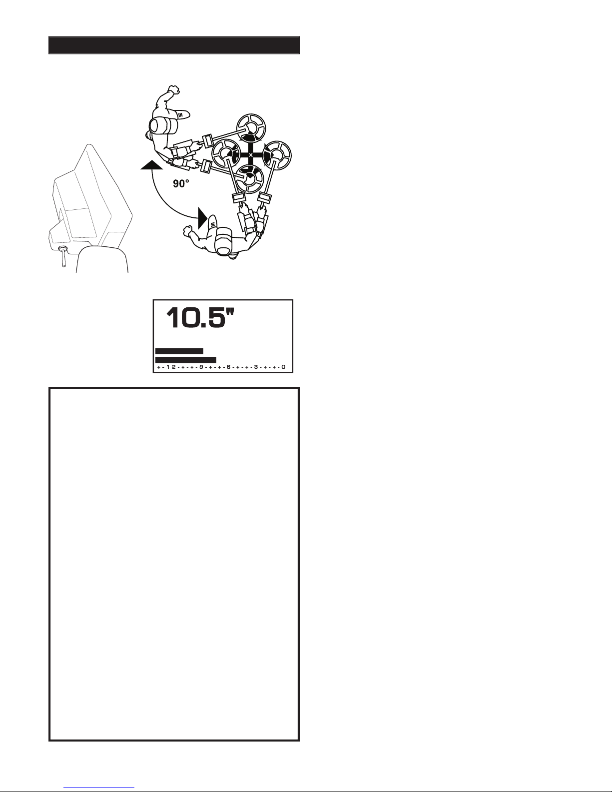
10. Viewing Angle
...................................................................................................................................................................
24
Pro Options
...................................................................................................................................................................................
25
Audio
..........................................................................................................................................................................................
27
1. Ratchet Pinpointing
.............................................................................................................................................................
27
2. S.A.T. Speed
........................................................................................................................................................................
27
3. Tone I.D.
..............................................................................................................................................................................
28
4. V.C.O.
..................................................................................................................................................................................
28
5. Modulation
...........................................................................................................................................................................
28
G.E.B./Trac
.............................................................................................................................................................................
29
6. AutoTrac
®
.............................................................................................................................................................................
29
7. Trac View
.............................................................................................................................................................................
29
8. Trac Speed
...........................................................................................................................................................................
30
9. Trac Offset
...........................................................................................................................................................................
31
10. Trac Inhibit
.........................................................................................................................................................................
31
11. Coarse G.E.B.
....................................................................................................................................................................
32
12. Fine G.E.B.
........................................................................................................................................................................
33
Discrimination
..........................................................................................................................................................................
34
13. Disc. Edit
......................................................................................................................................................................
34-35
14. Block Edit
..........................................................................................................................................................................
36
15-16. Learn Accept/Reject
.....................................................................................................................................................
37
17. Recovery Speed
.................................................................................................................................................................
38
18. Bottlecap Reject
.................................................................................................................................................................
39
19. Hot Rock Reject
.................................................................................................................................................................
40
20. Sweep Speed
......................................................................................................................................................................
21. Ground Filtering
................................................................................................................................................................
Display
.......................................................................................................................................................................................
43
22. Visual Disc.
........................................................................................................................................................................
43
23. Icons
...................................................................................................................................................................................
43
24. V.D.I. Sensitivity
................................................................................................................................................................
44
25. D.C. Phase
.........................................................................................................................................................................
45
26. Accumulate
........................................................................................................................................................................
46
27. Average
..............................................................................................................................................................................
46
28. Fade
....................................................................................................................................................................................
47
Preamp Gain
.............................................................................................................................................................................
48
29. Preamp Gain
......................................................................................................................................................................
48
Multi Frequency Method
.........................................................................................................................................................
49
30. 2 Frequency (Best Data)
....................................................................................................................................................
49
31. 2 Frequency (Correlate)
.....................................................................................................................................................
49
32. V.D.I. Normalization
..........................................................................................................................................................
50
33. 1 Frequency (3 kHz)
..........................................................................................................................................................
50
34. 1 Frequency (15 kHz)
........................................................................................................................................................
50
EEPROM Programs
................................................................................................................................................................
51-52
Program Settings Chart
..........................................................................................................................................................
53-54
Glossary
.........................................................................................................................................................................................
55
Warranty
...................................................................................................................................................................................
56-57
Service
..........................................................................................................................................................................................
58
Warranty(UK)
..........................................................................................................................................................................
59-60
Page
Page 2
Assembly
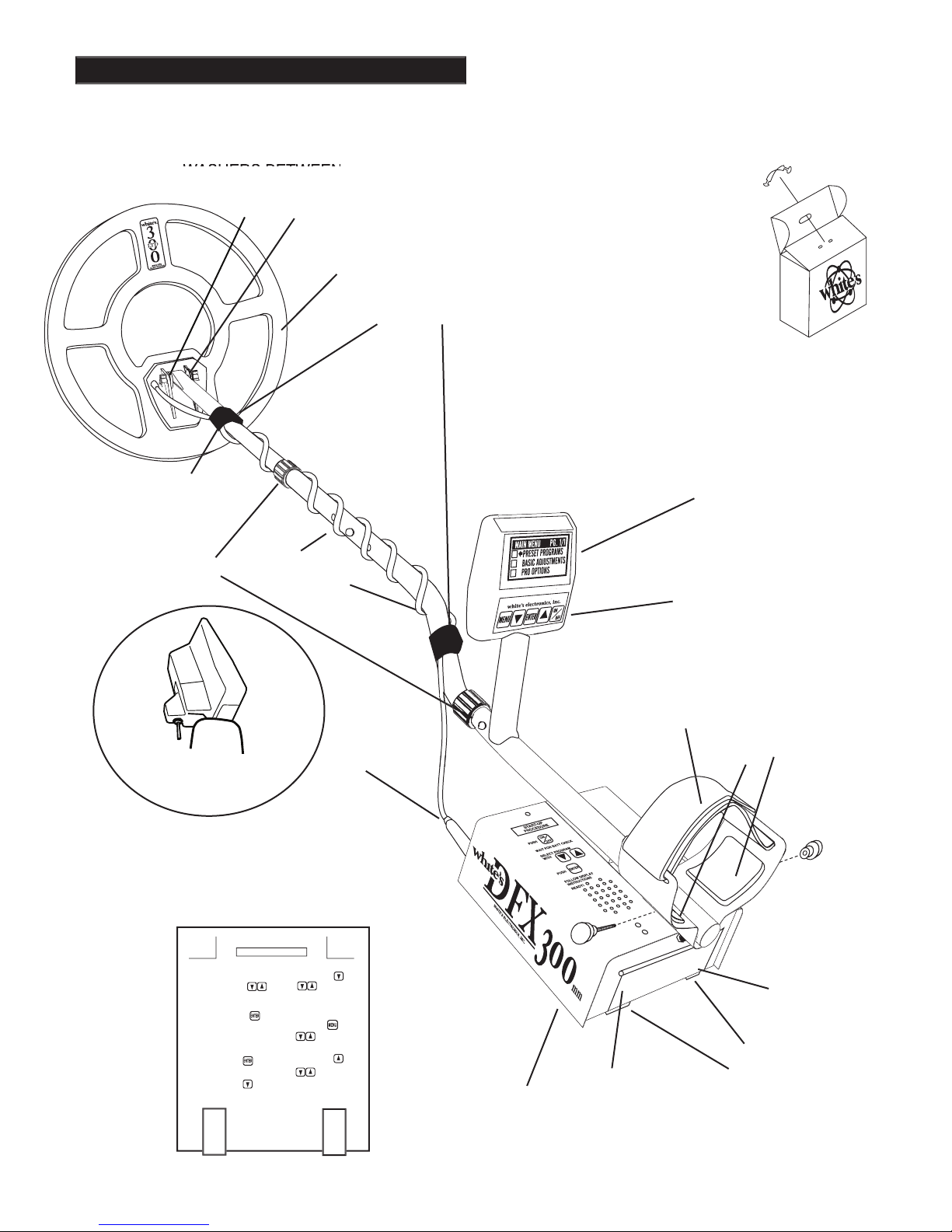
Chapter 1 DFX™ Assembly
“S” ROD
CABLE
CAMLOCKS
WASHERS BETWEEN
2/ BASIC ADJUSTMENTS
3/ PRO OPTIONS
4/ TARGET ID NUMBERS
5/ TARGET ID ICONS
6/ TARGET ID SIGNAGRAPH
®
7/ BATTERY STRENGTH
CABLE RETAINERS
JACK
TOUCH PADS
ADJUST CONTROLS
COIL
Trigger behind display activates
depth reading and
COIN PROGRAM
SQUEEZE & RELEASE TRIGGER
AFTER BATT. CHECK.
SCROLL OPTIONS
ATER BATT. CHECK USE
TO SCROLL CURRENT SETTINGS
OR MAKE ADJUSTMENTS
GROUND BALANCE ONL
Y
WHILE SEARCHING HOLD THE
TRIGGER AND PRESS
BATTERY CHECK
WHILE SEARCHING, HOLD THE
TRIGGER AND PRESS
REVERSE DISPLA
Y
WHILE SEARCHING. HOLD
THE TRIGGER AND PRESS
PRESS FOR
LIGHT/DARK BACKGROUND.
RELEASE TRIGGER
BACKLIGHT
IN SEARCH MODE, HOLD THE
TRIGGER AND PRESS
RELEASE TRIGGER
PUSH
AIR/GND BALANCE
IN SEARCH MODE PRESS
TO RE-AIR/GND BALANCE
VIEW ANGLE
WHILE SEARCHING HOLD
THE TRIGGER AND PRESS
RELEASE TRIGGER
PUSH
"HOT KEY" SHORTCUTS
for a few seconds then release.
Twist and insert each end of
top of shipping carton into
second fl ap.
CLEVIS
LOWER
Page 3

7.
Remove the protective paper from the two black
elbow cup foam pads. Carefully align pads on the
inside of the elbow cup, one on each side of the
center rod, and press fi rmly into place.
Adjust the elbow cup strap so that it is loose
enough for you to slide your arm in and out with-
out loosening each time you want to set the de-
tector down. The elbow cup strap provides extra
leverage and control. However, some prefer not to
use it.
Install battery as described in the next section,
decal facing down
tacts facing toward inside of battery compartment.
It should be noted at this point that the detector
may not work as expected indoors due to the high
degree of metals used in modern construction. It
is best to tune and practice out-of-doors to ensure
buried targets will not produce the normal depth
naturally lost and settled in the ground. Due to the
matrix, and the sophistication of the ground rejec-
tion circuitry, it may take a number of years for
freshly-buried targets to respond at true depths and
discrimination accuracy. The best way to determine
true detection depth is in real search conditions.
Your DFX is designed to automatically turn
itself OFF if the trigger on the grip (or another
control) “is not used” for a period of 10-15
minutes. This protects the battery from damage
in case of an accidental turn on during travel or
pinpointing/depth reading (keeping the detector
operating) is encountered during each 10 minutes
of search. If searching an unusually area, free
of concentrations of metal, the DFX will make
to resume searching. So long as a good battery
remains, the DFX returns to the exact settings prior
to turning itself off.
Assembly Instructions
Remove all parts from shipping carton and
check the assembly page to make sure all parts are
present.
2.
There are rubber washers between clevis/lower
rod and loop ears.
Use only nonmetallic washers,
fi ber bolt, and thumbnut to secure loop/search
coil to clevis/lower rod.
3.
Unlock "S" rod camlock and insert clevis/low-
er rod into curved "S" rod so that stainless steel
the adjustment holes in the curved "S" rod. Turn
camlock to secure. The second or third adjustment
holes are suitable for average size adults. Individ-
uals 6' or taller should use the fully extended posi-
tion. Individuals well over 6' tall should purchase
the optional
4.
Unravel loop cable and wind the cable around
the clevis and rod assembly, fi rst revolution over
the top of the rod. Wind cable all the way to the
top of the curved "S" rod, about fi ve revolutions.
Use the black cable retainers, one near the loop,
and one near the top of the curved "S" rod, to hold
the loop cable in place.
5.
Unlock control box rod camlock and insert
curved "S" rod so that stainless steel spring clip
buttons line up and lock into the rod on top of the
control box. The "S" rod is designed to curve up
toward the display. However, those who prefer to
assemble the "S" rod to curve down toward the
ground. Turn camlock to secure. Plug loop con-
nector into control box, screw lock ring to secure.
6.
8.
9.
Chapter 1 DFX™ Assembly
Grip the instrument by the handle, with your
arm in the elbow cup with strap secure, and sweep
the loop/search coil over the fl oor. If the instrument fi t feels uncomfortable, adjust the elbow cup
by removing and repositioning the bolt/thumbnut
and installing in one of the optional positions. If
necessary, readjust clevis/lower rod length with the
spring clip buttons so that the search coil can be
held near the fl oor without requiring stooping over.
Page 4
Chapter 2 DFX™ Batteries
Standard Battery Holder
The standard battery holder (blue decal) holds
eight “AA” cell batteries. Alkalines are recom-
mended for use with this battery holder.
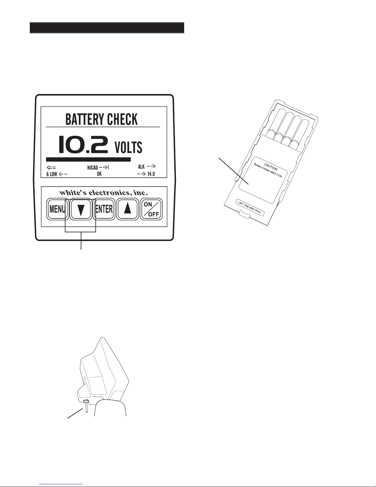
2.
Non-alkaline batteries can be used in this holder.
When non-alkalines or rechargeable “AA”
cells are used, detecting time (before replacement/
recharge) may be reduced.
3.
"LOW BAT" will automatically appear on the
display when the batteries become too low to prop-
erly operate the detector.
4.
The battery compartment opens by gently pull-
ing down on the front of each of the two latches
catch and hinging open the door.
The non-rechargeable battery holder can use many
different types of batteries, including rechargeable.
This holder is designed for standard size penlight
Battery lengths shorter than this will likely cause
problems with this power supply.
When the instrument is turned on the battery volt-
age will momentarily appear after the opening
display. The detector will then continue to the
MAIN MENU
ing operation, squeeze and hold the TRIGGER and
press the ARROW DOWN control.
ARROW DOWN
TRIGGER
Page 5
Chapter 2 DFX™ Batteries
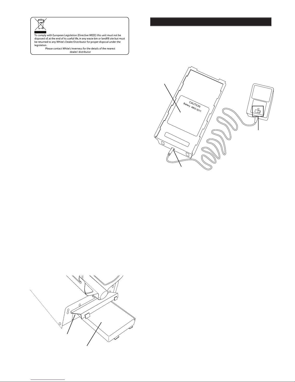
A rechargeable battery (green decal) is provided
with your instrument. This battery can be recharged
hundreds of times as long as the battery hasn't been
Full charge can be achieved anytime during the
discharge cycle. When using the QUICK charge
on the following page for charge time. A full charge
will last ten to fi fteen hours of normal use.
Battery life will vary with temperature, the number
of targets found, and the exact settings used. Six
hours is not unusual for extreme high performance
experienced extensive use.
QUICK CHARGE
is for USA ONLY. It is not
available on 220-240 volt.)
Your charger has a
OVERNIGHT charge options. Always check the
position of this switch prior to charging. Always
follow the charge hours on the chart on the follow-
ing page when the QUICK charge setting is used.
Overcharging with the QUICK charge setting will
damage the system.
Standard Battery Holder
battery holder) by applying gentle upward
pressure on the tab of the door so that it unlocks.
exposing the cell positions.
2.
Remove any old cells from the holder. Note the
and (-) for each position marked inside the cell tray.
Install new “AA” cells
noting carefully the cor-
rect (+) and (-) positions.
If the cells are installed incorrectly, the detector
may require service by an Authorized
Service Center.
3.
4.
Insert the battery holder into the detector so that
the decal is facing down, with the battery
holder door tab and metal contact points facing
toward the inside of the battery compartment.
Close the battery compartment door and secure
the two latches on the bottom of the case. Hook
the front of each latch fi rst, then press down on the
rear.
QUICK
CHARGE
OR OVER-
COMPARTMENT DOOR
WITH DECAL SIDE DOWN AND
Page 6
Chapter 2 DFX™ Batteries
6.
The battery will lose its charge during stor-
age. If stored inserted in your instrument, this loss
will be more noteworthy. It is recommended that
the battery be removed from the instrument dur-
ing periods of storage. It is not advisable to store
rechargeable batteries for long periods of time
without use. If however, storage is necessary, store
without a charge (discharged).
7.
Do not discharge the battery in devices other
than your metal detector. Unnecessary discharging
and/or an absolute discharge will reduce battery
life and may damage the battery. Unlike older re-
chargeable battery designs, the rechargeable battery
provided with your detector can be recharged at any
time.
Regardless of whether or not it already has a
partial charge, memory will not occur.
8.
White's has provided the leading edge of re-
chargeable battery technology with your instru-
ment. Disregard all advice which confl icts with the
above recommendations. Care for batteries pro-
vided by other manufacturers, or with other White's
models, may vary.
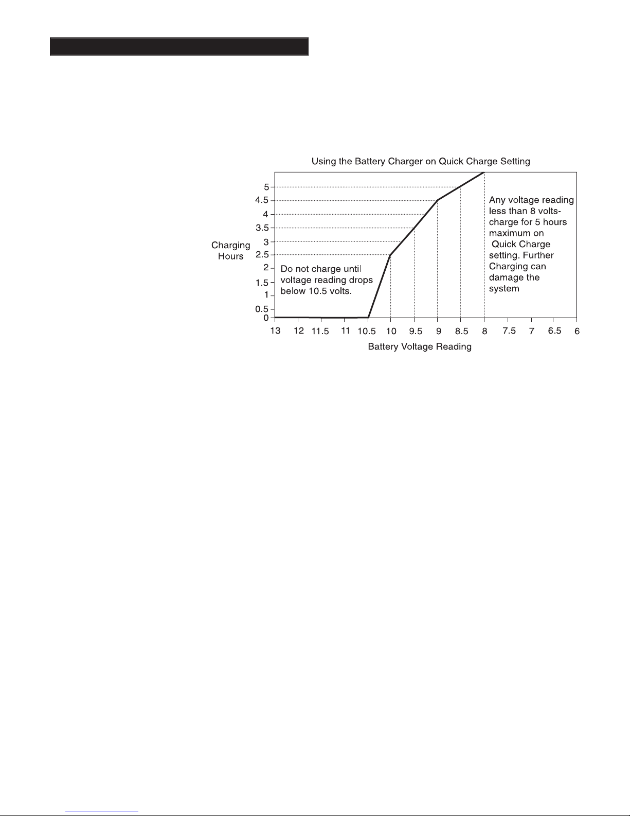
Charging
There is no harm charg-
ing overnight using the
OVERNIGHT charge
battery's current condition.
However, before charging
with the QUICK charge
condition by inserting bat-
tery into the instrument and
turning the instrument ON.
If the instrument will not
turn ON, or if voltage tests
eight volts or below, charge
fi ve hours with the QUICK
charge. If the battery voltage tests any other volt-
proper QUICK charge time.
2.
To charge, insert the charger plug into the battery
pack jack, located near the plastic tab and
metal contact points.
3.
Plug the charger into a standard wall outlet. (110
volts for USA models).
4.
Again, the QUICK charge setting uses the above
chart for a specifi c charge time. OVERNIGHT is
designed to charge the battery in as little as fourteen
hours. However, no harm will come to the system
leaving it charging for several days.
5.
It is normal for the battery and charger to get
warm during use. However, if either the battery or
the charger gets too hot to hold or deforms due to
the heat, discontinue use and return for testing.
Page 7

Chapter 2 DFX™ Batteries
Volatile memory
temporarily holds any program
changes or settings not yet saved in a Custom Pro-
gram.
Short-term
or volatile memory is retained so
long as a good battery remains in the detector. To
recover volatile memory immediately squeeze and
release the TRIGGER once the detector is turned
ON. If the battery is removed all volatile memory
is lost.
Long-term
memory (programs saved in
Custom Programs) is automatically saved for up to
ten years regardless of whether a battery is in the
detector or not.
When using fresh batteries, the voltage will initially
check somewhere in the 10 to 14 volt area. Unlike
will quickly drop to between 9 and 10 volts and
plateau there for most of its life. Once the recharge-
able battery voltage drops below this plateau, it will
quickly drop below a usable voltage level (eight
volts) and thus require a recharge.
Low Battery
will
automatically appear on the display when the bat-
tery reaches eight volts.
Like a personal computer, there are times (such as
low battery conditions) when the microprocessor of
a metal detector becomes out of sequence with the
rest of the circuitry. This is often noted by peculiari-
ties in the nondiscrimination or pinpointing (TRIG-
GER squeezed) modes. Symptoms may be blaring
or silent non-discriminate or pinpoint modes, depth
indication inaccuracies or general abnormal opera-
tion. To correct such diffi culties "re-boot" by:
2. Turn ON wait for MAIN MENU to appear.
3. Open battery door and remove battery while
detector is still ON.
4. Wait one minute, reinstall battery, turn
detector ON, and check for proper function.
Use of maximum backlight may reduce battery life
by up to 50%, depending on battery type.
Rechargeable batteries gradually deteriorate. As
they age they do not provide the life-per-charge
they did when new. This is expected, and not
grounds for replacement under warranty. Addition-
charging with the QUICK option,
use, or a defect due to a problem with a White's
warranted DFX
charger, is covered.
Page 8
Chapter 3 DFX™ Quick Start
Quick Start Instructions
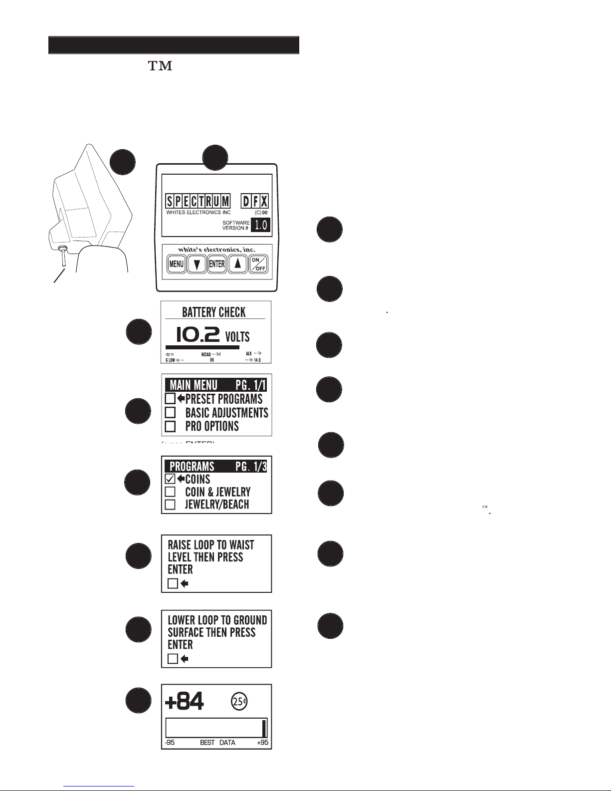
Quick Start
With the TRIGGER in the center position,
press the ON/OFF control and an automatic
The display will momentarily show an
opening screen which lists the
software
version
The display then shows a
battery
check
The last automatic display screen to appear
is the
MAIN MENU.
Press the
ENTER
control.
)
The Preset Program
COINS
will appear on
the MENU. Press
ENTER
.
You will be prompted to raise the search
coil (loop) to waist level. Press
ENTER
.
This
air balances
the DFX
("BEEP
Next, the
ground balance
prompt appears
asking you to lower the search coil (loop) to
the ground. Press
ENTER.
Ground mineral-
ization will be balanced out.
("BEEP
The last screen will be the live search
ground and listen for a solid repeatable/con-
icons tell what likely coin lies below. V.D.I.
number/chart on top of control box and Sig-
naGraph® provide greater detail. Squeeze
the trigger for pinpointing and depth and it's
time to dig!
TRIGGER
CENTER
1
3
4
2
After you have assembled the DFX™ and inserted the
battery pack, follow these simple steps to start
treasure hunting!
1
2
3
4
5
5
6
7
8
6
7
8
Page 9
Chapter 3 DFX™ Quick Start
Search Fundamentals
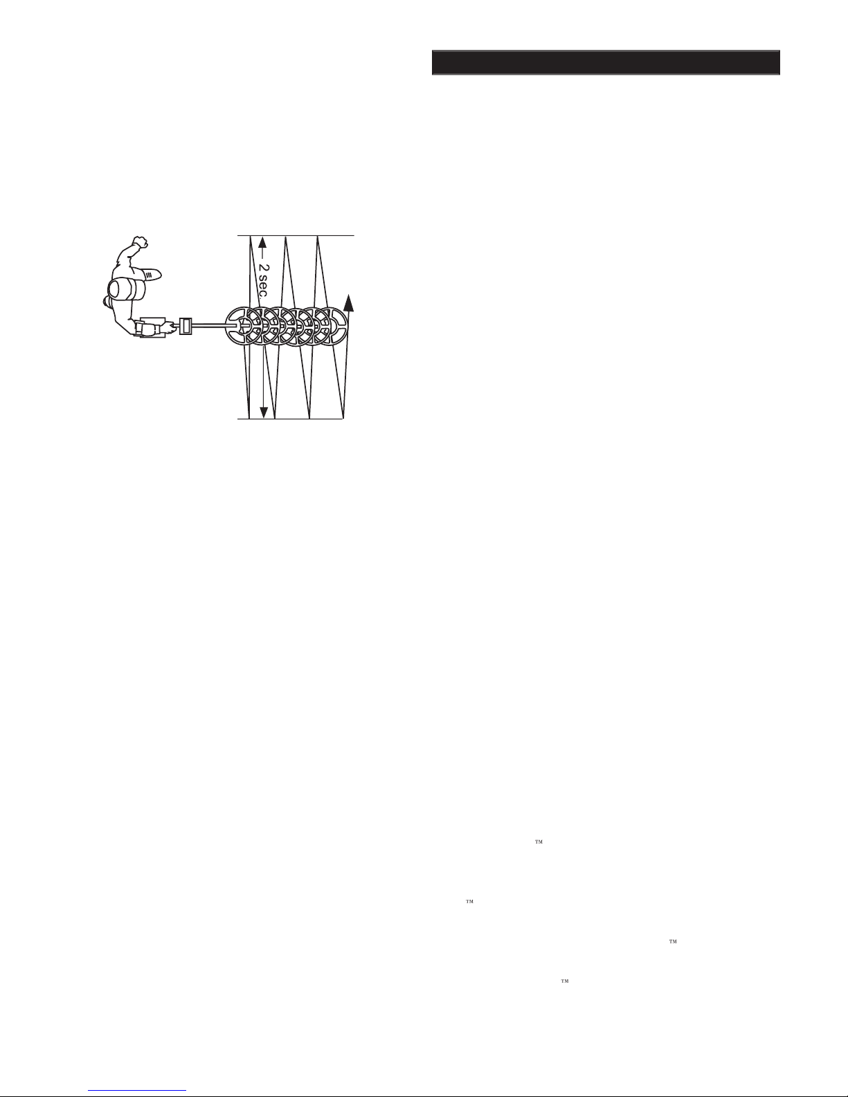
The loop/search coil must be in motion (sweep-
ing from side-to-side) for this instrument to
respond to metal.
Practice a smooth sweep of
the loop from side-to-side keeping the loop close
to the ground throughout the swing.
Each pass of
the loop should take approximately two seconds
from right to left, two seconds to return from left
to right.
Walk forward slowly. Take small steps no greater
than half normal strides. Make sure each pass of
the loop overlaps the last by at least half the length
of the loop. Do not lift the loop at the end of each
To become comfortable with sweeping the loop
takes some practice. Try to loosen up and fi nd a
comfortable grip on the handle. Premature fatigue
may result from gripping the handle too tightly, im-
properly adjusted rod or elbow support, and limited
body movement. Hold the handle loosely. Adjust
the rod and elbow support for comfort and keep the
elbow strap loose. Use your arm, shoulder and even
your back a little to allow a smooth even sweep of
the loop.
Now that you're sweeping the loop smoothly over
the ground, you will notice that the detector starts
making sounds
Not all sounds are good
targets; some trash targets also make the detec-
tor
beep.
As the loop is swept over the ground, ignore the
display and concentrate on the sounds the detector
makes.
As the loop is passed over metal that is likely trash,
the sound will be inconsistent. Trash targets typi-
cally produce a shorter, sputter-type sound, that
is often broken or double in nature. Place a steel-
pop bottlecap on the ground. Pass the loop over it
different loop sweep speeds. Note that an aluminum
twist-off bottlecap
cannot
be used as it is a different
type of target. Also note that very old rusty bottle
caps may start reading as quarters due to the elimi-
nation of the iron alloy through deterioration. Once
familiar with the sound typical bottle caps produce,
tion, saving more time for evaluating possible good
targets.
As the loop passes over metal that is likely a good
target, a more consistent and smooth sound will be
heard. A good target typically produces a longer,
more solid sound. Place a quarter on the ground
familiar with the sound of a good target.
Why Air/Ground Balance?
When the display prompts you to AIR BALANCE
by holding the loop at waist level and press EN-
TER. The DFX
ground balancing by measuring temperature and
other variables that affect electronic circuits. The
"beeps" and you lower the search coil to the
distance above the ground that you will be search-
ing. Press ENTER to have the DFX
"cancel/track
out" or GROUND BALANCE the ground miner-
then automatically "tracks
out" the varying mineralization as you continue to
Page 10
Chapter 3 DFX™ Quick Start
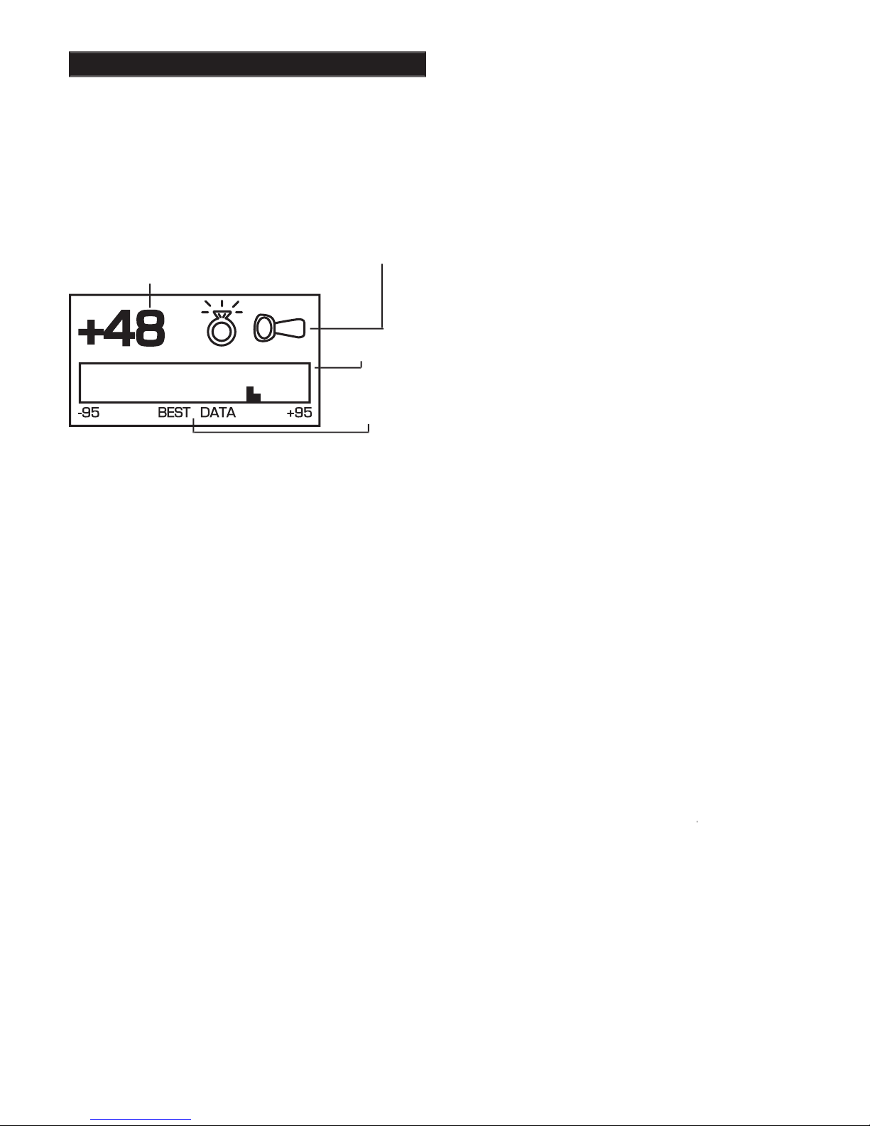
VISUAL
SIGNAGRAPH BAR-
GRAPH
In the upper left hand-side of the display there is
a V.D.I. number that corresponds to the V.D.I.
control box. It also corresponds to the Discriminate
Edit feature allowing you to reject or accept targets
based on their V.D.I. reference number. There are
and "-" numbers for ferrous (iron) targets. Rejected
V.D.I. numbers may not appear if the VISUAL
DISCRIMINATION feature is ON. Reasonably
consistent V.D.I. reference numbers (± fi ve digits),
in a desirable area of the chart is a vote for digging
the target.
2. Possible Target Identities ("Probable or most
likely target")
To the right of the V.D.I. number, possible target
identities will be represented graphically. These
graphics are called ICONS. A fairly consistent indi-
cation of a desirable target is another vote to dig
the target. One or two possible target icons may
appear. There is signifi cance to which icon appears
fi rst. The fi rst target to appear is always the most
likely, the second is another possibility, slightly less
likely than the fi rst.
3. SignaGraph
®
The SignaGraph
®
at the bottom of the display
provides a fi nal vote as to whether or not the target
A.
Sweep the loop over the target several times
®
doesn't fi ll the screen with information from past
loop sweeps. An operator has limited time to look
®
information again, sweep the loop over the target
®
information can be slowed or speeded (FADE
RATE) to operator preference. This is completed
in the PRO OPTIONS under DISPLAY. Automatic
AVERAGING and/or ACCUMULATING of Sig-
naGraph
®
information is also available (See PRO
OPTIONS).
B.
Valuable targets will show up on the positive
the section located to the right of the zero.
Look for consistency. In ideal conditions, coins
zero. Trash produces several bars, sometimes on
both sides of zero.
D.
In less than ideal conditions, coins may produce
recognizably different pattern than valuable targets.
E.
One of the most visual benefi ts of the Signa-
Graph
®
is the ability to show a
smear
pattern
on iron targets that often fool the other methods
of identifi cation. An iron target will likely show
defi nite bars on both the negative and positive sides
of the SignaGraph
®
smearing
all the way
produce such obviously wide patterns. In very bad
ground conditions, a good target may have a few
eralization. However, the pattern will show mostly
positive bars, in a fairly narrow tall group.
CURRENTLY IN
Page 11
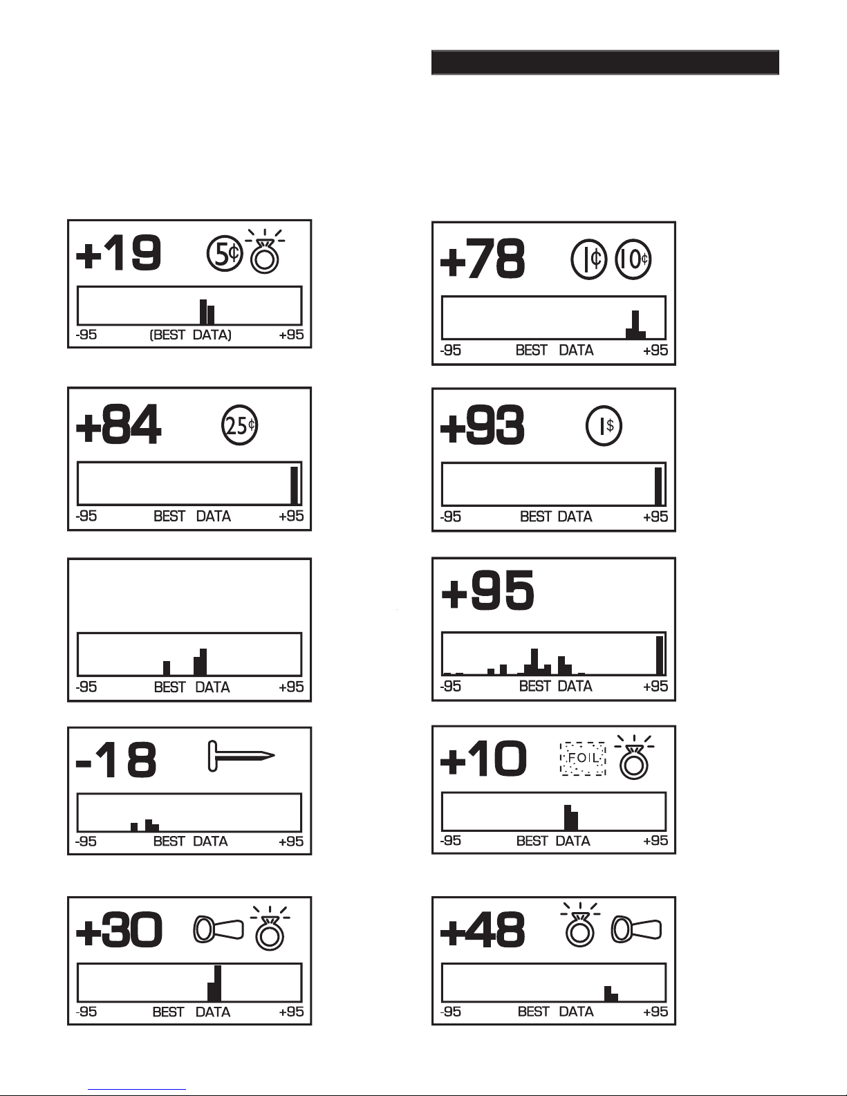
Chapter 3 DFX™ Quick Start
small (or half)
Quarter.
Could
or large silver
jewelry.
dime.
If the
screw cap and
are displayed,
the target
could be an
zinc penny.
Large
also produce
this indication
REJECT
targets will
®
if
VISUAL DISC.
+95
ACCEPTED or
VISUAL DISC.
OFF
-18
ACCEPTED or
VISUAL DISC.
OFF.
Possible
CEPTED or
VISUAL DISC.
OFF.
Pos-
sible ring. +30
ACCEPTED or
VISUAL DISC.
OFF.
Possible
ACCEPTED or
VISUAL DISC.
OFF.
Page 12
Chapter 3 DFX™ Quick Start
Once the decision has been made to dig, move the
loop off to one side of the target area, squeeze and
hold the TRIGGER on the handle, and "X" the loop
over the spot where you believe the target to be.
Note that the TRIGGER also has a locked for-
ward position that accomplishes the same thing as
While the TRIGGER is being held, the loop doesn't
need to be moving to detect the target. The loop
may be moved slowly over the area. The display
will indicate depth in inches and will also show
the strongest reading to aid in pinpointing exactly
where to dig. The shallowest reading on the depth
display, the loudest sound coming from the speaker,
the center of the target. Don't forget to "X" the
target as pinpointing cannot be accurate unless the
target is swept from at least two different directions.
Once pinpointing is complete, release the TRIG-
GER, or return it to the center position.
Pinpointing takes practice. The standard loop pro-
vided with the DFX™ is a high-powered, 12 inch
design. This harmonically tuned loop's strongest
traits are in the detection depth and ground cover-
cal refer to the Advanced Pinpointing Techniques
on this page.
THE TRIGGER
Advanced Pinpointing Techniques
Targets that are near the surface, because
they give a wider response, are harder to
and the loop swept over the area, you may
slightly above the ground, releasing and re-
squeezing the TRIGGER and again "X" ing the
target will aid pinpointing.
In the Basic Adjustments, DC Sensitivity
shallow targets better.
3.
In the PRO OPTIONS under AUDIO, V.C.O.
The depth reading has two indication bars.
The top bar shows the current distance from
the target, and the bottom bar shows a memory
of the strongest reading. These two bars will be
even with each other when the loop is directly
over the center of the target.
THE TARGET
Page 13

Chapter 3 DFX™ Quick Start
Permission
- Prior to searching and digging you
must have permission to search private property,
from the owner or caretaker.
Laws
- Know the laws that apply to the area you
are going to search. Laws vary a great deal with the
City, County, State, and Country, regarding the use
of metal detectors. Be respectful of private prop-
erty, public property, and the laws which govern the
use of metal detectors.
Tools
- Care must be taken to dig in a way that is
friendly to the landscape. Tools and methods vary a
great deal with the area, season, and types of target
you are recovering. Check with your dealer for
recommended tools and methods for your area.
Trash
- When searching, remove all trash you come
across. This not only makes your future searches of
the area more productive; it promotes the hobby of
metal detecting.
Get Involved -
Your dealer knows of metal detect-
ing clubs and organizations which promote and
protect the hobby. A club is a great way to not only
learn good detecting habits, but to gain permission
to search areas as a group as well as have organized
competition hunts.
Reached from the MAIN MENU, the factory PRE-
Coins:
general purpose settings, discriminates (re-
jects) most common junk items like nails, foil, pull
tabs, and hot rocks; and responds to most coins and
large jewelry. Use in lawns, parks, and playgrounds
where lots of trash rejection is desired.
Coin & Jewelry:
less discrimination (less trash
rejection), desirable because of the high degree of
variance found in jewelry alloys. More digging
required. Good program for lawns, parks, and play-
grounds. Use screen in conjunction with sound.
Jewelry & Beach
Relic:
even less discrimination than Coin & Jew-
elry or Jewelry & Beach, all types of metals except
Brass, lead, aluminum, as well as copper, silver,
will also respond . Suitable for all signifi cant targets
tions.
Prospecting:
NO AUDIO DISCRIMINATION. All
metals respond with
beep
only for metals that could be gold. Dig only V.D.I.
number (possibility gold) targets and avoid iron.
Targets which cause an audio response, without
causing a V.D.I. number to appear on the display,
frequency gold-shooting detectors will respond
better, this mode will offer good results for the oc-
casional nugget hunter by responding to nuggets in
the six-grain and heavier category.
Page 14
Chapter 4 DFX™ Basic Adjustments
After you have had some fi eld experience, you may
want to make some changes to the basic settings
of your detector.
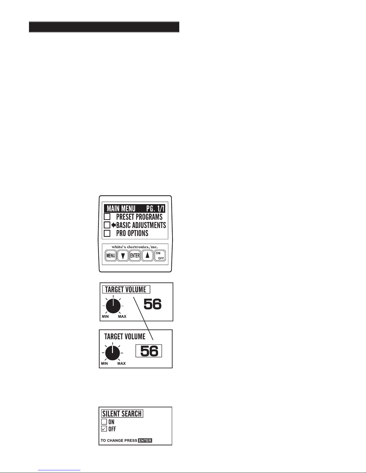
From the search mode press
MENU
will ap-
pear on the display. Use the ARROW controls to
move the pointer to Basic Adjustments,
and then
press ENTER.
You may now
use the ARROW
down
control to scroll
through the Basic Adjust-
ments.
Using the fi rst adjustment screen (TARGET VOL-
UME) as an example, the screens with a
graphic
control knob
require you to fi rst
press ENTER
then use the ARROW up and down controls to
adjust.
Note: when ENTER is pressed the square
controls.
After adjusting press MENU
and use
the ARROW controls to continue viewing/setting
other Basic Adjustments, or squeeze and release the
TRIGGER to begin searching
Adjustment screens with an on/off selection need
only for you to press ENTER to change setting.
Pressing ENTER again changes back to the original
THE TITLE MOVES TO
THE SETTING
ADJUST THE SETTING
ADJUSTMENT
- To quickly increase to
decrease to minimum, hold
the ENTER and press AR-
ADJUSTMENT
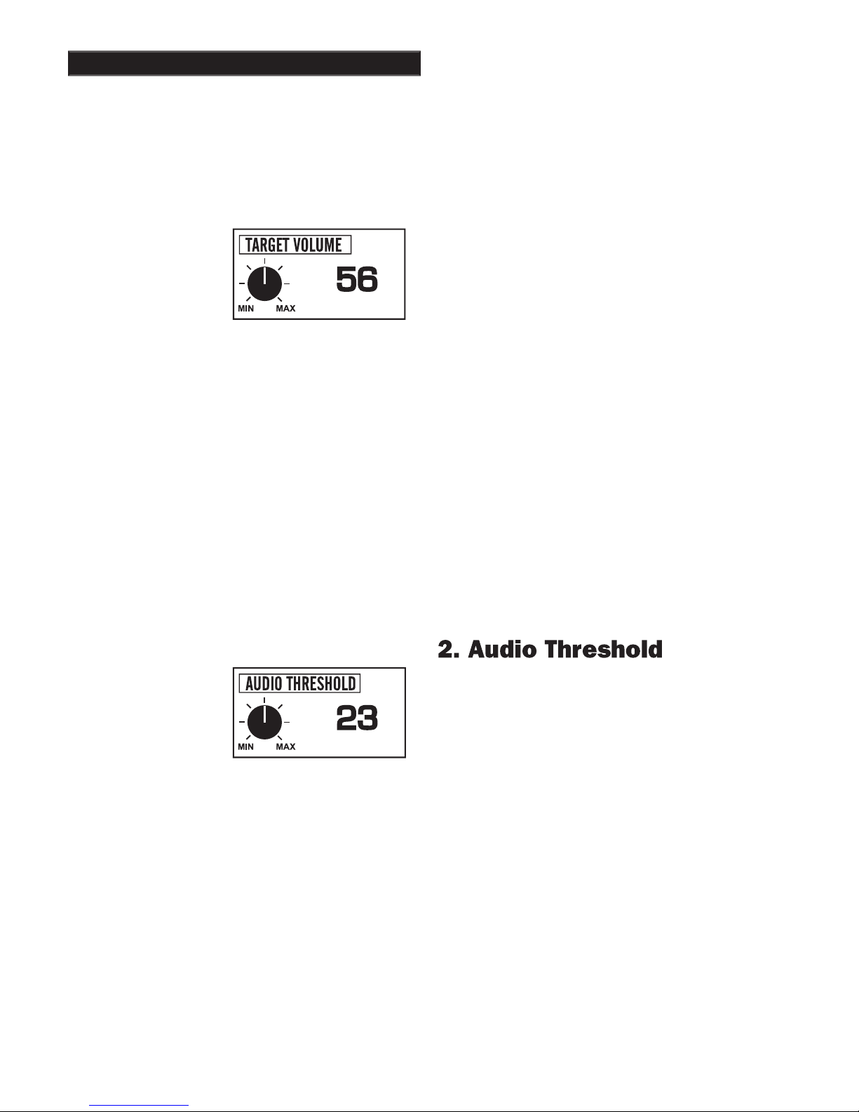
1. TARGET VOLUME -
How loud a target beeps when detected.
2. AUDIO THRESHOLD -
The slight hum or background sound heard continuously during searching.
3. TONE (AUDIO FREQUENCY) -
Selects the frequency or pitch of sound the detector produces.
4. AUDIO DISCRIMINATION -
The ability to reject trash, different sounds for different types of targets.
5. SILENT SEARCH -
The ability to operate without the threshold or background hum.
6. MIXED-MODE -
DC non-discriminate mode, working simultaneously with AC discrimination mode.
7. A.C. SENSITIVITY -
Degree instrument is responsive to signals in the discriminate (motion) modes.
8. D.C. SENSITIVITY -
Degree instrument is responsive to signals in non-discriminate (non-motion)
modes.
9. BACKLIGHT -
Used in dark conditions to light the display improving visibility.
Adjusts the display for low or high temperature visibility.
Page 15

Chapter 4 DFX™ Basic Adjustments
All the MENU items are tied together so that the
ARROW up and down controls scroll through every
adjustment screen. If you continue to press the
ARROW
down
you can go beyond the last BASIC
ADJUSTMENT (View Angle) and into the PRO
OPTIONS. If the ARROW
control is pressed
after VOLUME, you will be scrolling backwards
through the options starting with the end of the Pre-
of the PRO OPTIONS.
An important feature of the ARROW controls; If a
BASIC ADJUSTMENT has been made (for exam-
ple Volume) and the trigger has been squeezed and
released to return to a search mode, you can return
to the volume adjustment simply by pressing either
of the ARROW controls. This shortcut returns to
the last adjustment that was made thereby allowing
an operator to switch directly from a search mode
to the adjustment currently being fi ne tuned. This
feature is desirable as you start using BASIC AD-
JUSTMENTS or PRO OPTIONS that are located
further down the menu listings, or any adjustment
that may require some trial and error to fi nd the ap-
propriate setting.
If care is taken to use a desired adjustment screen
last (just prior to squeezing and releasing the TRIG-
GER for a search mode), Custom Programs can use
this ARROW RETURN feature to allow quick easy
access to the most used feature. Use that feature
releasing the TRIGGER for searching. Then during
that adjustment screen.
control box for fi eld reference.
NOTICE:
must be turned on and air/ground
balanced in any mode, then turned off. "HOT KEY"
Squeeze & release TRIGGER
SCROLL OPTION -
After battery check, use AR-
ROWS to scroll all the current settings /menus.
AIR/GROUND BALANCE -
In search mode,
press ENTER to re-Air/Ground Balance.
While searching,
hold the TRIGGER and press ENTER.
BATTERY CHECK -
While searching, hold the
TRIGGER and press ARROW
down.
Squeeze and
release TRIGGER to return to searching.
REVERSE DISPLAY -
While searching, hold
the TRIGGER and press ARROW DOWN. Press
ARROWs for light/dark background. Light or dark
background will not change battery life. It will
make the display easier for some to read, particular-
ly in certain light conditions. It will work in com-
bination with backlight. Reversed display is only
BACKLIGHT -
In search mode, hold TRIGGER
ARROWS to set.
VIEW ANGLE -
While searching, hold the TRIG-
GER and press ARROW
press ARROWS to set.
Page 16
A. LOAD
will activate a prior custom pro-
gram stored in that position. After you have
LOAD and press ENTER, to use that program.
B. SAVE
saves your current settings in that
custom position with either a generic name or
the current program.
is the preferred method. Select
NAME and press ENTER. You may now use
the ARROW and ENTER controls to name
your custom program. NAME automatically
pressed MENU.
Custom EEPROM Programs
Saving Basic and Pro Option
adjustments for future use.
program positions. They will remain permanently
in the DFX
memory regardless if the machine
is turned off or the battery removed. Custom EE-
PROM Programs can be changed at any time by
program. EEPROM is a special type of computer
memory made for this purpose, (Electrical-Eras-
able-Programmable-Read-Only-Memory).
Chapter 4 DFX™ Basic Adjustments
TRIGGER
THEN PUSH
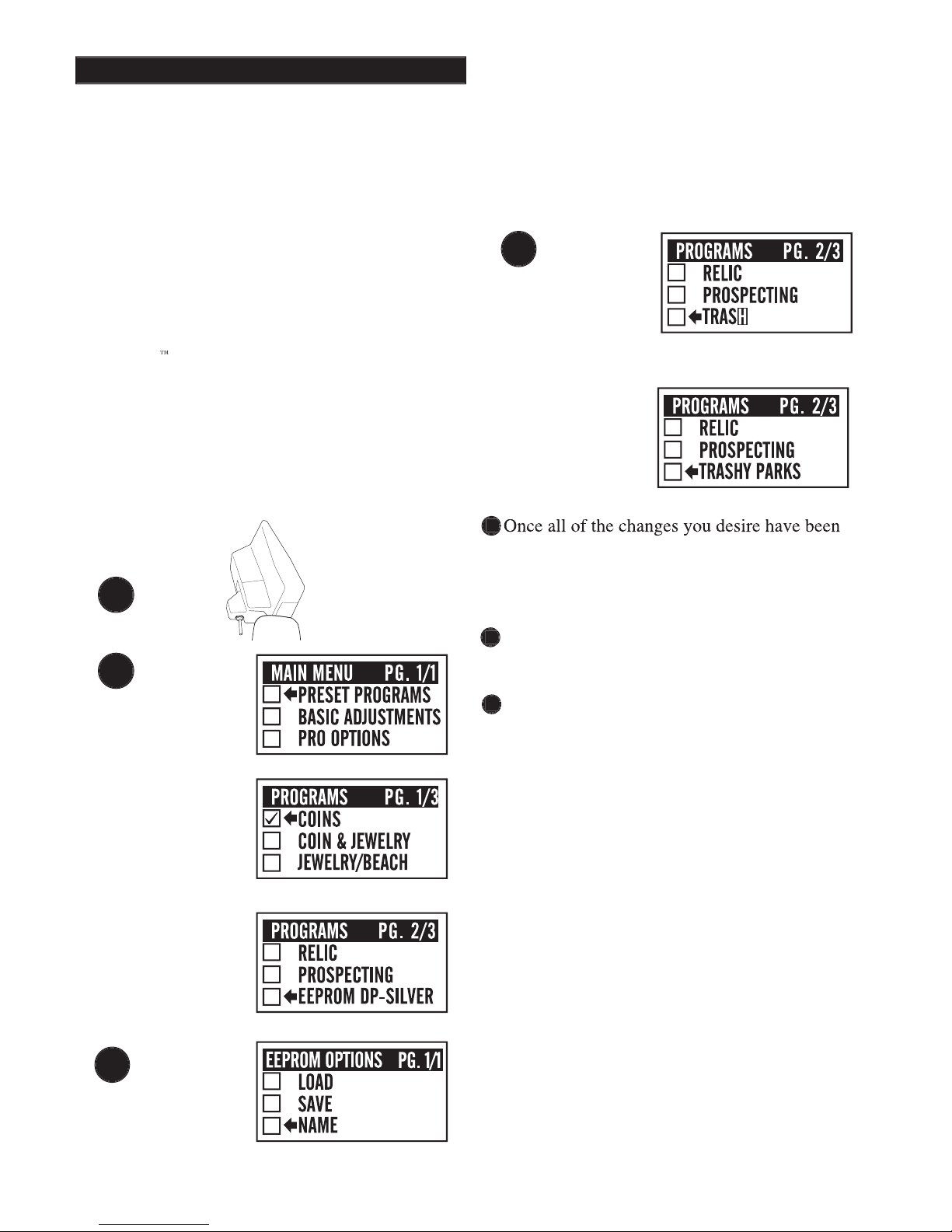
Once all of the changes you desire have been
made to any Preset Program or existing Custom
Program, squeeze and release the TRIGGER as if to
Use the ARROW controls to select one of the
four Custom Programs then press ENTER.
You now must make one of three choices (use the
ARROW controls to make your selection):
Once all of the changes you desire have been
2.
2.
3.
3.
You now must make one of three choices (use the
3.
4
1
2
1
2
3
3
Page 17

Chapter 4 DFX™ Basic Adjust-
4. To NAME,
use the ARROW controls to select
the fi rst symbol, number, or letter of the name and
press ENTER. Use the ARROW controls to select
the second symbol, number, or letter of the name,
press ENTER. And so on using up to sixteen digits.
To leave a space, use the ARROWS to select the
point where no symbol or letter appears and press
ENTER. If you make a mistake and press ENTER
when the digit is not as you desire, simply keep
pressing ENTER until that digit is again fl ashing,
then use the ARROWs to select the correct digit and
again press ENTER. It is wise to name the custom
program something that relates to what it is used
for. For example "TRASHY PARKS", "GHOST
TOWN", "NIGHT HUNT", "COMPETITION", etc.
Once the name is fully assembled press MENU.
5.
Once you have SAVED and pressed ENTER, or
NAMED and pressed MENU, there are four direc-
tions you can go:
A.
Squeeze and release the TRIGGER to con-
tinue searching using your new custom program.
B.
Press ENTER, select LOAD and press
ENTER to continue searching using your
new custom program.
C.
Press MENU to return to choose or develop a
different program than what you stored.
D.
Turn the detector OFF.
6.
When the detector is turned back on, regardless
of whether a battery pack was left in the detector or
not, your custom program will be ready for you to
use again and again. Simply select it, press ENTER,
on-screen instructions for Air/Ground Balance and
then search.
7.
If you SAVE or NAME a program, then decide
you no longer want to keep it, you can replace it
with a new program using the same procedure
erased when a new program is stored in that posi-
tion.
8.
You can NAME a custom program and at a later
date replace the program while maintaining the
gram, then use the SAVE method which maintains
the old name while storing the new program. To
keep the same program with a new name, fi rst
LOAD that custom program, Air/Ground Balance,
then press MENU and go to that custom position
ENTER. You can now develop a new name for the
old program.
- When a Custom Program is
that program is also stored. This has advantages
particularly for those who manually set the Ground
Balance for speciality applications. The automatic
Air/Ground Balance sequence will always override
manual settings. To access the last Ground Balance
desired Custom Program then press ENTER. Select
LOAD and press ENTER. Do not Air/Ground Bal-
release the TRIGGER. The last Ground Balance
Ground setting is not available, the instrument will
Return ARROW Key
- The last Basic Adjustment
or Pro Option screen used is remembered by your
Custom Program. From the search mode, either
ARROW control will access the last Basic Adjust-
ment or Pro Option screen used. This allows easy
Factory Preloaded EEPROM PROGRAMS
described on pages 53 and 54.
4. To NAME,
4. To NAME,
4. To NAME,
4
Page 18
Chapter 4 DFX™ Basic Adjustments
How loud a target
beeps
when detected.
controls and press ENTER. The current volume
level sounds continuously. The number designating
the current level is shown on the right side of the
display. To the left, the graphic knob indicates the
relationship of the current setting to minimum and
maximum levels.
Use the ARROW controls to select the volume level
you desire. Volume level will select the loudest
possible sound a shallow target can produce. High
volume levels will slightly reduce battery life.
Press MENU and use the ARROWS to continue
viewing and/or adjusting Basic Adjustments, or
Tip
- Select the loudest
comfortable level, lower
with headphones, higher
without. Settings from
48 - 63 are available.
The slight hum or background tone which is nor-
mally heard continuously during searching.
will sound continuously. The number designating
the current level is shown on the right side of the
display. To the left the graphic knob indicates the
relationship of the current setting to minimum and
maximum levels. Note that the maximum threshold
level (42) is well below the minimum VOLUME
level. Thus with the THRESHOLD at maximum,
old levels will slightly reduce battery life.
Press MENU.
Tip -
Select the lowest
available
Page 19

Chapter 4 DFX™ Basic Adjustments
3. Tone (Audio Frequency)
detector produces.
controls and press ENTER. The current TONE
will sound continuously. The number designat-
ing the current level is shown on the right side of
the display. To the left, the graphic knob indicates
the relationship of the current setting to minimum
pulse
dio frequency that you can hear comfortably and
provides the best defi nition for your ears. Press
MENU.
Tip -
If you have trouble
select low TONE levels
frequencies, select high
TONE levels (high num-
are available.
4. Audio Disc.
The ability of the detector to reject trash by
producing different sounds for different types
of targets. Trash is rejected by going silent or
producing a broken "cut-short" sound. Valuables are
detected by a smoother more solid sound.
use the ENTER control to turn AUDIO DISC. ON
or OFF. When ON, specifi c targets will be accepted
or rejected based on the Program currently in use.
Audio Disc. turns ON or OFF the entire audio
discriminate feature. When OFF, all types of metals
produce an audio tone
under Discrimination, can specifi c targets (V.D.I.
numbers) acceptance or rejection criteria be altered.
Press ENTER.
Tip -
Use AUDIO DISC
ON for trash rejection,
AUDIO DISC OFF for
detection of all types of
Page 20

20
Chapter 4 DFX™ Basic Adjustments
5. Silent Search
The ability of the detector to be operated without
the threshold or background hum that is normally
heard continuously during operation. The
instrument is silent until a target is detected.
controls and use the ENTER control to turn
To function, SILENT SEARCH requires AUDIO
DISC ON and MIXED MODE OFF. SILENT
AUDIO DISC and MIXED MODE menu selection
to perform the silent search function regardless
of your AUDIO DISC and MIXED MODE
In Pro Options the Discriminate feature can
be used to accept all metal targets while using
ON the all metal pinpointing mode continues to
produce a threshold. This may not be noticed,
target center locating the threshold is not present.
However, releasing, re-squeezing, and holding the
TRIGGER with the loop at waist level a threshold
will be noted. Press ENTER.
Tip -
A threshold hum
and ground conditions.
and reduced AUDIO
THRESHOLD doesn't
AUDIO
DISC
SELECTION
ON
OFF
ON
OFF
ON
OFF
ON
OFF
SILENT
SEARCH
SELECTION
OFF
OFF
ON
ON
OFF
OFF
ON
ON
SELECTION
OFF
OFF
OFF
OFF
ONONON
ON
THRESHOLD
ALL-METAL
TION
SILENT SEARCH
SILENT SEARCH
SILENT SEARCH
SILENT SEARCH
Page 21

21
A unique hybrid operating mode. It is an all-
metal (DC non-motion, non-discriminate) mode,
working simultaneously with a discriminate (AC
motion discrimination) mode. It is two modes, one
detecting everything and another discriminating,
operating at the same time.
press ENTER control to turn MIXED MODE ON
or OFF.
AUDIO DISC needs to be ON and SILENT
perform properly. See chart on (page 20). MIXED
MODE ON will automatically override AUDIO
DISC selections to perform the MIXED MODE
function.
When Mixed Mode is on, all types of metals will
produce a sound (beep).
Discrimination Channel - When the loop is
Discrimination Channel - When the loop is
in motion
targets accepted by the discriminate
program will produce a high-pitched
beep
Targets rejected by the discriminate program will
produce a lower pitched
beep
low-pitched
beeps
are directly determined by the
discrimination settings. An operator can select
discriminate settings through the selection of an
entire Program or by adjusting the accept and
reject V.D.I. numbers in the Pro Options under
Discrimination (EDIT).
All-Metal Channel -When the loop is not in
All-Metal Channel -When the loop is not in
motion, or moved slowly,
motion, or moved slowly,
all types of targets
will produce the same low-pitch
beep
metal channel will by nature detect deeper than
the discrimination channel. Deeper targets will
produce a lower volume sound when the loop is
moved slowly over the area.
Tip -
Advanced operators can
gain extra depth by monitoring
the all-metal and discriminate
channels simultaneously,
checking depth and digging
targets too deep for the
discriminate channel alone.
about the target, Pro Options
TONE I.D. and or V.C.O. can
Chapter 4 DFX™ Basic Adjustments
Page 22

Chapter 4 DFX™ Basic Adjustments
Used to select the appropriate sensitivity (degree
that the instrument is responsive to signals) while
being used in the discriminate modes (those which
require movement of the loop).
controls, and press ENTER. Use the ARROW
controls to set the level of sensitivity shown by the
number on the right. Press ENTER.
have a direct effect on detector stability. A.C.
to allow stable, predictable performance. Set a
lower level if the detector behaves erratically.
Tip -
well for most conditions.
conditions. Increased
detection depth if stability
can be maintained.
Tip-
once the TRIGGER is
squeezed and released
to go to a search mode,
you can return to the
ARROW control. Settings
from 1 - 85 are availabLE.
8. D.C. Sensitivity
Used to select the sensitivity (degree that the
detector is responsive to signals) while the
detector is being used in non-discriminate (ALL-
METAL) modes. These are modes that do not
require movement of the loop to respond. D.C.
controls, and press ENTER. Use ARROW
controls to select the desired D.C. SENSITIVITY
level shown by the number on the right. Press
ENTER. D.C. SENSITIVITY levels should be
predictable operation while allowing for reasonable
pinpointing.
A.C. and D.C. Sensitivity Adjustments are
traditionally the way to alter detection depth and
Tip -
Typically, lower D.C.
far better than high
settings. High settings
will however, produce
as non-discriminate mode
squeezed), MIXED-
AUDIO are dramatically
available.
Page 23

23
Used in dark conditions to light the display,
improving visibility.
to select the desired BACKLIGHT level. The
BACKLIGHT level will be visible on the display.
The current level is shown on the right side of
the display. The graphic control knob shows the
relationship of the current setting to minimum
The maximum backlight setting will reduce
battery life by as much as 50% depending on the
type of batteries and how long it is used. Lower
BACKLIGHT settings will have signifi cantly less
drain on battery life.
When the detector is fi rst turned on, it is
normal for the backlight to be on during the
opening display and BATTERY CHECK. If the
BACKLIGHT is off, it will fade when the MAIN
MENU display appears. If the BACKLIGHT is
ON, it will continue until turned off manually or a
different program is selected. BACKLIGHT can
be saved as part of a custom program, for example
When Backlight is ON and the TRIGGER
is squeezed and released to begin searching,
the display to warn you of the extra battery duty.
EMERGENCY BACKLIGHT -
If in the
dark
you cannot see the display to turn the
BACKLIGHT on, holding the TRIGGER and
pressing MENU will bring up the BACKLIGHT
press ARROW
to select a level you can see the
display. Squeeze and release the TRIGGER to
continue.
Tip -
as needed, for acceptable
display visibility. Backlight
the higher the battery
are available.
CAUTION
If the instrument is turned ON and the
EMERGENCY BACKLIGHT sequence is
used, the BACKLIGHT will stay ON only
while you stay in that program. Pressing
MENU and selecting another program will
turn BACKLIGHT OFF, if BACKLIGHT
is not also ON in that particular program.
If in the dark at the time the instrument
is turned ON, you may need to squeeze
use the EMERGENCY BACKLIGHT
you desire, press ENTER, press ENTER
for Air Balance, and press ENTER for
Ground Balance. Use the EMERGENCY
BACKLIGHT ON sequence a second time
if the BACKLIGHT fades in that program.
Unlike past Spectrum
®
instruments, the
DFX
BACKLIGHT is no different than
term volatile memory. However, factory
preset programs use the OFF (0) setting
Chapter 4 DFX™ Basic Adjustments
Page 24

Adjusts the display for visibility in low or high
temperature conditions.
trols and press ENTER, use the ARROW controls
to make changes. The current level is shown on
the right side of the display. The graphic control
knob indicates the relationship of the current set-
ting to minimum and maximum levels. Squeeze
VIEWING ANGLE has no impact on battery life.
EMERGENCY VIEWING ANGLE PROCE-
DURE
heat prior to use, you may not be able to see the
display to adjust VIEWING ANGLE. Press the
ON/OFF control, hold the TRIGGER and press
ARROW
trols to fi nd a VIEWING ANGLE level that allows
you to read the display. Squeeze and release the
TRIGGER to begin searching. Like the BACK-
LIGHT, you will lose your custom VIEWING
ANGLE setting if you change Programs. You
may need to use the EMERGENCY VIEWING
ANGLE PROCEDURE to see the display. Select
the program you desire, use the ENTER control
to enter, Air/Ground Balance, then again use the
EMERGENCY VIEWING ANGLE PROCE-
DURE if the display is unreadable. VIEWING
ANGLE is preset at average levels in the factory
preset programs. The display may be unreadable at
either of the extreme settings in a particular envi-
ronment. Custom VIEWING ANGLE settings will
be saved when Custom Programs are stored for
future use.
Tip -
the display typically will be-
come slower at responding.
er numbers) speeds the
display and improves vis-
display may become diffi cult
to see. Settings toward MIN
tions result throughout the
day or nights search, you
VIEWING ANGLE adjust-
display visibility. Settings
from 1- 50 are available.
Chapter 4 DFX™ Basic Adjustments
Page 25

25
Chapter 5 DFX™ Pro Options
AUDIO
1. RATCHET PINPOINTING -
Pinpoint feature, automatically detunes for center location.
2. S.A.T. SPEED -
Self Adjusting Threshold or Auto-tune, automatically maintains threshold.
3. TONE I.D. -
Assigns each V.D.I. target number its own special tone or sound.
4. V.C.O. -
Pinpoint or non-discriminate feature, increases pitch or tone with target strength.
5. MODULATION -
Motion modes produce the same, or different volume, based on target depth.
G.E.B./TRAC
6. AUTOTRAC
®
Automatically updates Ground Balance during searching.
7. TRAC VIEW -
TRACK appears on right side of display during AUTOTRAC
®
adjustments.
8. AUTOTRAC
®
SPEED -
Dictates when AUTOTRAC
®
adjusts Ground Balance.
9. AUTOTRAC
®
OFFSET -
Positive or negative AUTOTRAC
®
(over, or under kill).
Prevents tracking the ground during target detection.
(Manual Ground Balance) Coarse viewing, or overriding automatic.
(Manual Ground Balance) Fine viewing, or overriding automatic.
13. DISC. EDIT -
Change V.D.I. (target reference numbers) accepted (detected), or rejected status.
Speeds EDIT by dragging ACCEPT or REJECT with ARROW controls.
Target samples can be used to show or teach ACCEPT discrimination.
Target samples can be used to show or teach REJECT discrimination.
Speeds target responses, so close together targets each respond.
How strongly the instrument rejects or breaks up on iron.
Degree the instrument is responsive to signals in the +95 (hot rock) category
20. SWEEP SPEED -
Adjust signal sampling width thus the ideal loop/search coil sweep speed.
21. GROUND FILTERING -
How much circuitry (high-pass fi ltering) used to separate ground/trash signals and targets.
22. VISUAL DISC. -
Rejected V.D.I. numbers and ICONS do not appear on display.
23. ICONS -
Graphic display representation of metal targets, ON/OFF.
24. V.D.I. SENSITIVITY -
Response intensity to produce a display indication & 3rd V.D.I. digit@ 86 and higher.
25. D.C. PHASE -
Measurement of ground, or metal target, during pinpointing.
26. GRAPH AVERAGING -
SignaGraph
®
information collects over multiple loop passes.
27. GRAPH ACCUMULATING -
Emphasizes common or predominate SignaGraph
®
28. FADE RATE -
Clears or fades noncurrent SignaGraph
®
information (bars).
29. PREAMP GAIN -
Selects the intensity of the signal received from the loop.
MULTI FREQUENCY METHOD
30. 2 FREQUENCY (BEST DATA) -
Transmits and processes at both 3kHz and 15 kHz frequencies (salt eliminated).
Automatically chooses data from the most reliable frequency (based on both magnitude and phase) for each specifi c target.
31. 2 FREQUENCY (CORRELATE) -
Transmits and processes at both 3kHz and 15 kHz frequencies (salt eliminated).
Compares data at 3 kHz and 15 kHz. Target signals that do not provide reasonably predictable information at both are automati-
cally rejected. Iron typically doesn't compare predictably between frequencies, improved iron rejection can be expected.
32. V.D.I. (NORMALIZED) -
2 Frequency modes (Best Data and Correlate) automatically have V.D.I Normalized ON
as it is required for these modes to operate predictably. Differences at 3 kHz and 15 kHz skew the well known traditional (6.59
kHz) V.D.I. chart/numbers painted on the top of the DFX control box. Normalization recalculates signals for this traditional
V.D.I. number chart. OFF expands/compresses portions of this V.D.I. scale (depending on the 1 frequency used.).
33. 1 FREQUENCY (3kHz) -
Operates at 3 KHz providing for superior high iron mineral use (no salt present) particularly
for high conducting silver/copper alloys. Normalized ON maintains traditional (6.59 kHz V.D.I. chart/numbers. Normalized OFF
34. 1 FREQUENCY (15 kHz) -
Operates at 15 kHz providing in lower mineralized areas (no salt present) particularly
for lower conducting gold/nickel alloys. Normalize OFF signifi cantly expands lower end of V.D.I. chart/numbers compressing
higher end of the scale.
Page 26

26
The
PRO OPTIONS
intricate adjustments available on this model. The
PRO OPTIONS are divided into fi ve major cat-
egories of menus, structured similar to the Basic
Adjustments. Methods of entry, adjustment, exit,
To enter the PRO OPTIONS from a search mode,
press MENU and the MAIN MENU will appear.
Use the ARROW controls to select PRO OPTIONS
PRO OPTIONS menu (PG. 1/2
Page one of two
).
The ARROW controls are then used to select the
desired PRO OPTION category.
The six major categories have options specifi c
to their titles. For example, all the options under
AUDIO have to do with the way the audio circuits
of the instrument behave. Once a category has been
ROW controls can then be used to scroll through all
the options even beyond that category i.e., beyond
PRO OPTIONS, back to PRESET PROGRAMS,
only reappear if MENU is again pressed, or at spe-
cifi c times during scrolling (to offer short cuts).
From this point forward, we will assume that you
know how to use the MENU control, the Arrow
Controls to make a selection, the ENTER control
to enter or select that option, the Arrow Controls to
make adjustments, and the MENU to exit. Remem-
ber, squeezing and releasing the trigger returns to a
from the search mode to the last menu or adjust-
ment display used.
Chapter 5 DFX™ Pro Options
Be aware that changes you make to a
Program are only in effect as long as
you continue using that Program. If the
detector is turned OFF, the Trigger must
be squeezed and released to recover short
term (volatile) memory upon turning the
detector ON. If you want to keep the
changes you made to a specifi c program
over an extended time period (days or
weeks),
or through battery changes
or through battery changes
entire Program must be saved in a Custom
EEPROM Program position.
CAUTION
Page 27

27
Chapter 5 DFX™ Pro Options
Pinpointing feature, automatically detunes for easy
target-center locating.
ON - Automatically aids in pinpointing. When the
TRIGGER is squeezed and held for pinpointing,
RATCHET PINPOINTING will shrink the size of
the signal as the loop is passed over the target area
unless the loop is moved too far away from the
target center.
OFF - When OFF, the signal will remain original
Manual shrinking is completed by squeezing and
releasing the TRIGGER several times as the loop
is passed over the target. Manual shrinking can
completely eliminate the target. If the target no
longer responds after manual shrinking, move the
loop away from the target, squeeze and release the
TRIGGER, and again sweep the loop over the area.
If the target is a metal, it should again respond.
Tips -
Use the ON set-
ting until experienced at
THRESHOLD, OFF (0), or ON (1-10).
Without S.A.T. SPEED (a setting of 0), changes in
the ground (and the passage of time) will tend to
produce changes in the THRESHOLD sound. The
TRIGGER will have to be squeezed and released
repeatedly to maintain the THRESHOLD. This is
particularly noticeable in non-discriminate modes,
although S.A.T. SPEED will also tend to add
THRESHOLD changes.
metal detectors dating back to the 1970's. It adds
a loop-motion requirement to modes which are
ordinarily non-motion. It is also known to produce
more mineralized than the surrounding ground)
which change with different speed selections.
Only enough S.A.T. SPEED required to maintain
beach hunting and relic hunting require slightly
faster speeds (higher numbers), and prospecting
requires the fastest settings (highest numbers).
Tips -
greater stability particularly in non-discriminate modes or
when sensitivity levels are maximized. Typically, faster
conditions. Settings from 0 - 10 are available.
Page 28

28
Chapter 5 DFX™ Pro Options
3. Tone I.D.
Assigns each V.D.I. number its own distinct tone or
pitch. Target ranges can easily be identifi ed by their
pitch of their sound. Reject targets still break up or
Tone I.D. is used in the discriminate or motion modes.
When ON, each V.D.I. target number has its own
audio frequency or pitch (191 different pitches). The
higher the V.D.I. number, the higher the pitch. Where a
target indicates on the V.D.I. scale can be immediately
recognized. The sound that rejected targets produce
will still be canceled or modifi ed (broken up) by the
discriminate circuit.
The 191 different pitches or tones activated with
TONE I.D. cannot be adjusted as to their pitch. Each
V.D.I. number's sound is predetermined by the factory
and is not adjustable, nor will they shift with TONE
Tips -
elry, and relic searching.
Can be used in combina-
tion with MIXED MODE
4. V.C.O.
Voltage Controlled Oscillator produces a higher pitched
tone the stronger the target becomes.
Voltage Controlled Oscillator is a feature that will only
work in the non-discriminate modes. When it is ON,
the stronger the response the higher the pitch of the
function when the trigger is squeezed for pinpointing
when activated in a discriminate mode. It will func-
tion full time in the non-discriminate (ALL-METAL)
modes.
D.C. SENSITIVITY settings will dramatically change
the performance of V.C.O. D.C. SENSITIVITY set-
tings above a level of 35 may peak the audio pitch too
mended, particularly in trashy areas where targets are
close to each other.
Tips -
The best aid avail-
able for pinpointing. Also
can work well in combina-
tion with MIXED MODE to
the non-discriminate chan-
5. Modulation
Allows motion modes to produce different volume
levels based on target depth.
Modulation is used in the discriminate or motion
modes. When ON, it allows the depth of the target to
dictate the volume of the response. Thus deep targets
can be easily recognized by their lower-volume sound.
If OFF, the discriminate or motion modes will produce
the same volume of response on all detected targets
regardless of depth. The use of MODULATION al-
lows for the singling out of deep targets in the standard
discriminate mode. It may save time by eliminating
the checking of each target with the depth indication in
the pinpoint mode.
Tips -
If you have excellent
out deep targets by their
default (standard setting)
for all factory Preset Pro-
grams. If your hearing isn't
the best, the OFF setting is
Page 29

29
®
AUTOTRAC
®
allows the instrument to automati-
cally readjust the Ground Balance setting during
occurring changes in the ground mineral of an
detection depth and stability are enhanced. AUTO
TRAC
®
is recommended for typical search condi-
tions. If, however, a great deal of decomposed
man-made iron is encountered, AUTOTRAC
®
OFF,
or a reduced AUTOTRAC
®
SPEED is advised.
AUTOTRAC
®
operation is affected by TRAC
INHIBIT.
Tips -
Use ON for most
search conditions.
When ON, "TRACK" appears on right side of dis-
play when AUTOTRAC
®
makes adjustments to the
Ground Balance setting.
TRAC VIEW offers a way to observe Autotrack-
ing. When ON, "TRACK" will appear momentarily
on the right-hand side of the display just above the
®
while AUTOTRAC
®
is adjusting.
This information is valuable when attempting to
determine an appropriate Trac Speed. It may also
be a valuable aid in determining the relative ground
conditions. Reoccurring "TRACK" would indicate
diffi cult ground. In average ground it is desirable
to see some
tracking
occur (see TRAC SPEED).
Tips -
TRAC SPEEDs to deter-
AUTOTRAC
®
automatically
adjusts Ground Balance.
Chapter 5 DFX™ Pro Options
Page 30

Chapter 5 DFX™ Pro Options
8. Trac Speed
Dictates when AUTOTRAC
®
adjusts Ground Bal-
ance.
Trac Speed allows adjustment of the amount of
ground mineral change required to cause Auto-
tracking to occur. At slower speeds (lower num-
bers) it takes a signifi cant change in the ground to
cause tracking to occur. At faster speeds (higher
numbers) it takes very little change in the ground
mineral to cause tracking to occur. The end result,
more tracking occurs at higher numbers than at
lower numbers. Too much tracking can cause errors
in the ground balance setting. Not enough track-
ing can result in the ground balance setting never
catching up with changing ground. TRAC VIEW
is used to see how much tracking is occurring.
Generally, a faster (higher number) TRAC SPEED
is needed for more consistent ground conditions.
for more inconsistent ground conditions. "TRACK"
appearing every three to fi ve sweeps of the loop is
the ideal setting when the ground conditions will
allow.
Tips -
It is desirable to
select a TRAC SPEED that
tracks the ground once
every three to fi ve sweeps
of the loop however, this
extremely consistent, or
extremely inconsistent
ground conditions, which
than this desired standard.
available.
Page 31

Allows AUTOTRAC
®
to track ground minerals
either positive or negative in relationship to the
correct setting (under, or over kill).
TRAC OFFSET allows the AUTOTRAC
®
feature
to track the ground slightly more or less than what
would normally be considered perfect, mostly for
experts that prefer a slight offset.
A slightly positive offset can be used to enhance
the responses of small metals (gold nuggets) in
highly-mineralized ground. Positive is indicated by
es the ground in the all-metal mode. Discrimination
A negative offset may be used to eliminate par-
ticularly troublesome "hot rocks" in areas that are
otherwise diffi cult to search. Negative offset is in-
dicated by a loss or slight decrease in the threshold
mode.
Tips -
Recommended only
for experienced opera-
tors who fully understand
ground rejection. Settings
from -10 - +10 are avail-
able.
Prevents AUTOTRAC
®
from tracking the ground
during target detection.
TRAC INHIBIT ON prevents the AUTOTRAC
®
feature from altering Ground Balance during the
detection of targets. This prevents the possibility
of tracking to the corrosion associated with most
metals. TRAC INHIBIT ON is recommended for
most searching conditions. Some metals do not
corrode (GOLD) and since tracking is extremely
important in high mineral conditions, the ability
to turn TRAC INHIBIT OFF is available. OFF is
Tips -
ON for most search
conditions, OFF for pros-
Chapter 5 DFX™ Pro Options
Page 32

rent automatic Ground Balance setting (Air/Ground
Balance) and/or manual overriding of the automatic
Ground Balance.
COARSE & FINE G.E.B. (Ground Exclusion
Balance, or ground rejection) allows manual over-
ride of the automatic balancing features to select a
major adjustments. FINE allows minor adjustments
near the COARSE setting.
Before attempting manual Ground Balance adjust-
ments, turn off AUTOTRAC
®
since it will alter
Balance will begin at the setting selected by the
Automatic Air/Ground Balance performed after
manual adjustment will cancel the manual setting.
To maintain a manual setting, the Automatic Air/
Ground sequence must be avoided by squeezing
Balance instruction appears. Air Balance instruc-
tions may appear during Basic Adjustment or Pro
Options selections following the manual adjust-
ment.
When manually adjusting the Ground Balance, it
is necessary to make an adjustment in COARSE
GER. The TRIGGER can be held in, and the loop
lowered and lifted over the ground to check for a
change in sound which would indicate imperfect
Ground Balance. To return to the Ground Balance
display for further adjustment, press either of the
ARROW controls. When perfectly Ground Bal-
Tips -
als or hot rocks. Settings
from 0 - 255 are available.
Chapter 5 DFX™ Pro Options
Page 33

Chapter 5 DFX™ Pro Options
FINE G.E.B. is used to make smaller adjustments
to the Ground Balance range on either side of the
COARSE setting. The FINE setting combines
with the COARSE setting to determine the actual
ground rejection level. To determine exactly what
level the automatic Air/Ground sequence selected,
it is necessary to check both COARSE and FINE
levels.
Manual Ground Balance will rarely be used for
perfect balancing as the automatic balance is
extremely reliable. It is generally used to off-
TRAC
®
OFFSET is used.
In COARSE or FINE, lower numbers indicate a
Ground Balance setting toward the negative side
of the V.D.I. scale (iron). Larger numbers indicate
a Ground Balance setting toward the positive side
of the V.D.I. chart (salt). Bad ground conditions
magnetic
(negative or low numbers) or
conduc-
tive
(positive or high numbers). COARSE and
FINE settings of 0 represent a ground rejection
FINE settings of 255 represent a ground rejection
level similar to a V.D.I. number of +10. This V.D.I.
range from -95 to +10 represents the ground rejec-
tion range of this instrument. If ground balance
COARSE setting, signifi cant loss in sensitivity can
be expected to targets which indicate in the V.D.I.
number range of 1 to 10. However, manual ground
balance doesn't exactly work like a discriminator,
where V.D.I. numbers are simply REJECTED. The
actual phase of Ground Balance is out of sequence
with most targets; thus some responses will oc-
cur even if COARSE & FINE G.E.B. are matched
exactly to a particular targets V.D.I. number.
Tips -
adjusted to the top of the
scale, 255, will automati-
cally bump up the Coarse
setting by one
justment can continue un-
to the bottom of the scale,
0, Coarse G.E.B. setting
down by one increment so
that fi ne adjustment can
continue uninterrupted.
The entire Coarse G.E.B.
are available, coarse and
fi ne.
Page 34

Chapter 5 DFX™ Pro Options
Allows for changing which targets V.D.I. or refer-
ence numbers are ACCEPTed (
detected
), or RE-
JECTed, (
discriminated out
) within the current
Program you are using.
the ARROW controls to view the V.D.I. numbers
from negative -95 to positive +95 that appear on
the right side of the display. These are the same
reference numbers that are listed on the top right-
hand side of the control box (V.D.I. SCALE or tar-
get chart). For each V.D.I. number, a √ will appear
to the left indicating whether the current program
will ACCEPT or REJECT targets that display that
number.
Use the ENTER control to change any desired
V.D.I. number to ACCEPT or REJECT status.
If you do not save the entire Program into a Cus-
tom Program, the changes you make in EDIT are
only in use as long as you continue to use that
program. The only exception being the temporary
then switch to COIN & JEWELRY, you lose all
editing you completed in the Coin Program. Each
time a factory Preset Program is ENTERed, all
unsaved settings are overwritten by the factory
recommended settings. Only the Custom Programs
will save your custom settings through Preset Pro-
gram selections.
Accepting a wider range of V.D.I. numbers will
have an impact on detection depth, particularly for
very deep targets that are diffi cult for the display
to identify. Positive +95 is one of the most signifi -
cant V.D.I. numbers. Some Preset Programs are set
The display uses positive +95 for many different
Will have a greater
than any other feature. Audio Discriminate
ON/OFF is located in the BASIC
ADJUSTMENTS, (page 19).
and
BLOCK EDIT
are
exceptions to the keystroke rule in that
they do not have a graphic control knob.
Tips -
The factory Preset
jor DISCRIMINATION EDIT
setups already defi ned and
changes in ACCEPT and
selected by choosing one
of these factory programs.
specifi c or unusual targets
you may want to either AC-
CEPT or REJECT. Settings
from -95 - +95.
Page 35

types of targets it cannot readily identify. There-
fore, if positive +95 is ACCEPTed, questionable
targets may be dug that indicate this number and
can produce some interesting recoveries.
A good
tip regarding positive +95: If a target indicates
95, and the depth display indicates it as being fairly
deep;
dig it
being fairly shallow, it is more likely to be trash or
a hot rock. HOT ROCK REJECT in the Pro Options
has 20 levels available for the acceptance or rejec-
tion of +95. An operator can adjust HOT ROCK
REJECTION to suit personal preference and area
demands. (See page 42.)
The fi rst 30 to 40 negative numbers below zero also
impact detection depth. Most iron indicates further
into the negative numbers. Thus the fi rst 30 to 40
negative numbers can often be ACCEPTed without
digging much iron. ACCEPTing from the posi-
tive numbers down as low as minus 30 to 40 has
the largest impact on the lower end of the positive
numbers. Sensitivity to small jewelry is increased.
However, sensitivity to foil is also increased. On a
beach or in a park that has lots of small foil, AC-
CEPTing down to minus 30 to 40 may not be practi-
cal. While ACCEPTing these minus numbers, a
reduced sensitivity setting may help eliminate some
of these small bits of unwanted foil.
ACCEPTing all V.D.I. numbers will produce the
best overall detection depth however, with the
amount of trash in most areas, searching with no
rejection is seldom practical. TONE I.D. is a more
practical choice. The idea of discrimination is to
ACCEPT V.D.I. numbers most likely to be valu-
ables and to REJECT the V.D.I. numbers most
likely to be trash. Digging ease, and acceptability in
an area will also decide the amount of ACCEPTed
V.D.I. numbers desired. No metal detector can
reject all trash while accepting all valuables. The
deeper you want to detect, the more trash you will
need to accept and dig.
The detector sees metals electronically; thus some
valuable and non-valuable targets may look identi-
cal to the detector. To select ACCEPT and REJECT
V.D.I. numbers is to gamble that the areas you
ACCEPT
will be good targets, and the
REJECT
will be trash targets.
A factory program which uses the law of averages
usually produces more good targets than trash. The
EDIT feature allows you to fi ne-tune the ACCEPT
desired targets, further improving these odds.
Chapter 5 DFX™ Pro Options
Page 36

Chapter 5 DFX™ Pro Options
dragging
ACCEPT
or REJECT with ARROW controls.
Allows major EDIT changes to be completed
quickly. EDIT is for individual V.D.I. number
changes and/or viewing of the current settings.
BLOCK EDIT is for changing multiple V.D.I.
numbers, or ranges.
and press ENTER. The ENTER control can be
used to select either ACCEPT or REJECT. The
ARROW controls can then be used to drag that
ACCEPT or REJECT status as far as desired
through the V.D.I. number range. When a V.D.I.
number or range of numbers appear that you want
press ENTER to change the ACCEPT/REJECT
desire. ENTER changes ACCEPT/REJECT; AR-
ROWS drag that ACCEPT/REJECT status; EN-
TER again changes ACCEPT/REJECT; ARROWS
drag that new ACCEPT/REJECT status, etc.
BLOCK EDIT not only saves time if large sections
of the V.D.I. target numbers are to be changed, it
also allows peace of mind in the certainty of how
all the V.D.I. numbers are set. In the same amount
of time it takes to view all the V.D.I. number's cur-
rent status in regular EDIT, you can set them the
way you desire in BLOCK EDIT.
Tips -
V.D.I. numbers are to be
changed, use BLOCK EDIT.
Caution:
You cannot view
the current settings or the
and ENTER. The arrows
can then be used to view
the settings. Whenever
the arrows are used while
change every V.D.I. number
viewed to the ACCEPT or
one appears on the display.
Page 37

Chapter 5 DFX™ Pro Options
teach the discriminator what metal targets you
desire to ACCEPT or REJECT.
the ARROW controls and press ENTER to turn
LEARN ON. The current selection is indicated by
the √ mark in square on the left of the display.
Once ON:
Squeeze and release the TRIGGER.
2.
the instrument by sweeping them one at a
time in front of the loop until the desired
accept or reject sound is heard.
3.
Press either ARROW control to return to
the LEARN selection display.
4.
Press ENTER control to select LEARN
OFF.
5.
Squeeze and release the TRIGGER to
return to a searching mode.
Tips -
target and an exact sample is available,
that specifi c target. If using a stan-
dard program and a specifi c unwanted
trash target is being detected, use the
gram to reject it.
If you do not return to the LEARN
the detector will continue to learn (AC-
CEPT or REJECT) every metal target it
encounters.
Selecting LEARN OFF after
you have learned a target is extremely
Iron alloys, such as steel bottle caps
or nails, should never be used for this
LEARN method of programming. Be-
cause of their inconsistent V.D.I. indica-
tions, iron alloys tend to scatter or other-
wise confuse the discriminate program.
If this occurs, it is best to turn the detec-
tor OFF, back ON, and re-ENTER the
desired Program to return to the original
factory preset discriminate settings.
CAUTION
As with EDIT, LEARN changes will only be tem-
porary until saved in a Custom Program.
If LEARN has been used to develop a discriminate
program, the ACCEPT or REJECT V.D.I. numbers
can be reviewed by using the EDIT feature.
Page 38

Chapter 5 DFX™ Pro Options
close together can each respond.
When a metal is detected, it takes a fraction of a
it can respond to another metal target nearby. The
time it takes to process the fi rst metal target signal
is called RECOVERY SPEED.
There are advantages and disadvantages to fast
RECOV-
ERY SPEEDS
RECOVERY SPEED
well in high trash areas. However, they will have
as double responses on shallow targets. Slower
RECOVERY SPEED
high trash areas. However, they will have bet-
ter responses on very deep targets. Slower speeds
also have more defi nitive discrimination sounds.
A custom setting needs to be found that suits the
preferences of the individual and the conditions in
the area. As a general rule, the closer together the
metal targets are in an area, the faster the recovery
gets, the slower the speed should be. Don't use the
fast speed if you don't need to.
Ground Filtering adjustments (page 44) will also
dramatically improve or degrade performance in
high trash.
Tips -
areas, slower speeds (low-
er numbers) for low trash
areas and/or improved dis-
crimination. Settings from 1
- 40 are available.
Page 39

Chapter 5 DFX™ Pro Options
Adjusts how strongly the instrument rejects or
breaks up on iron.
Most starting programs use the minimum setting.
As larger numbers are selected, more
bias rejection
The advantage of higher BOTTLECAP REJECT
iron rejection occurs. Trash becomes easier to iden-
tify by the broken sounds they produce.
The disadvantage of a high Bottlecap Rejection
the high degree of
bias
detector to cancel both responses. Another disad-
vantage is that all targets, iron and non-iron, tend to
TLECAP REJECT. The operator needs to fi ne tune
BOTTLECAP REJECT according to their prefer-
ences and the conditions being searched.
Tips -
sounds of iron, try increas-
available.
Page 40

Chapter 5 DFX™ Pro Options
Tips -
described or categorized
as either negative/magnetic
ductive (hot rock). Typically
a negative or magnetic
“cold rock” will respond in
the search mode, how-
ever, once the trigger is
squeezed for pinpointing it
ceases to respond. A posi-
tive or conductive “hot rock”
will continue to respond
during pinpointing.
their target like responses
compared to real metal
target responses in the +95
category. Settings from
Hot rocks (rocks higher or different in mineraliza-
tion than the surrounding ground) respond as +95
on the V.D.I. scale. Unfortunately in some ground
conditions very deep, small, or unusual real metal
targets may also indicate +95. In the past an opera-
tor would either accept +95 with the DISC EDIT
feature and hear hot rocks as a target response
“beep”, or reject +95 and not hear a target like re-
The HOT ROCK REJECT features allows a com-
promise between total rejection or total acceptance
of the + 95 V.D.I. indication. Disc Edit Accept or
Reject of +95 will only control the visual displaying
of +95 with the Visual Discrimination feature ON.
To reject or accept +95 with the audio discrimina-
tion, Audio DISC must be on, and the HOT ROCK
REJECT feature adjusted for your preference-re-
garding +95.
A HOT ROCK REJECT range of 0 to 20 is pro-
vided. At 0 the same characteristics can be expected
Whiteʼs models. At 20 the same characteristics can
be expected as EDIT REJECT +95 provided with
past Whiteʼs models.
At 10 a compromise between accepting +95 and
rejecting +95 is achieved. A hot rock may or may
not produce a target like response depending upon
many factors such as the actual size of the hot rock,
degree of difference between the hot rockʼs miner-
ground balance setting, and the Sensitivity/Gain
Hot Rock Reject provides for 19 shades of gray be-
tween totally accepting all hot rocks (0), and totally
rejecting all hot rocks (20).
Page 41

Tips -
Typically a competi-
tion or speed hunt would
when an operator would de-
sire the best performance
with a faster loop sweep
speed. Another area well
suited to faster loop sweep
speeds are large areas that
each other.
Typically high trash areas,
or older areas that deserve
a slower more methodi-
cal search, are ideal for
slower loop sweep speeds.
available.
The quickness the loop or search coil is passed from
to perform properly regarding detection depth and
discrimination. Sweep Speed is often a personal
preference feature. Individuals may like or dis-
like a particular model based on itʼs required ideal
of searching and a slower sweep speed for another
The SWEEP SPEED of the DFX is adjustable in all
A GROUND FILTER setting of 2 has a fi xed (not
An adjustment range from 1 to 20 is available. 1 is
the slowest ideal (best performing) loop or search
coil sweep speed, 20 is the quickest ideal (best per-
formance) sweep speed.
mance) loop sweep speed by controlling the width
of the target signal the detectors electronic circuit
dow (lower number settings) a slower loop sweep
dow (higher number settings) a quicker loop sweep
RECOVERY SPEED is highly interactive with
Generally faster RECOVERY SPEEDS are better
RECOVERY SPEEDS are better suited to slower
new dimensions to these features. SWEEP SPEED,
RECOVERY SPEED, and GROUND FILTERING
nation responds to both trash and valued metal
Chapter 5 DFX™ Pro Options
Page 42

Tips -
often described or cat-
egorized by the amount
of electronic fi ltering used
to distinguish between the
ground, trash, and valued
fewer the fi lters, the quicker
the metal detector can
eral metals targets close to
each other. However, de-
tection depth in mineralized
ground quickly diminishes
with fewer fi lters. Audio
discrimination sounds are
the electronic fi lters the
audio discrimination be-
comes more pronounced.
equals slower responses
and several targets near
each other become dif-
fi cult to sort out or respond
separately. Settings from 2
- 6 are available.
GROUND FILTERING is adjustable with the
DFX. The fi rst two primary fi lters are contained
within the hardware (electrical parts). The remain-
ing fi lters are contained within the computer soft-
ware allowing full user adjustment.
The DFX GROUND FILTERING has an adjust-
ment range from 2 through 6. At a setting of 2
mance in high trash areas of medium to low ground
mineralization. Combined with the RECOVERY
will pull some good targets from previously heavy
hunted high trash areas.
performance than 2 in slightly higher ground miner-
end Whiteʼs fi ltering ideal for medium to high min-
eralized ground.
fi ltering for extreme ground conditions. Although
in the past, two of those six were dedicated to visual
indications alone. The DFX 6 fi lter selection dedi-
cates all six to ground rejection, discrimination,
mineralized ground conditions the DFX with its
multifrequency salt/conductive mineral cancelation
performance levels never before available.
Chapter 5 DFX™ Pro Options
Page 43

When ON,
REJECT
ed V.D.I. numbers and their
on the display. When OFF, all V.D.I. numbers and
VISUAL DISC. "ON" eliminates both the V.D.I.
number
and
the ICON (NAIL, FOIL, PULL TAB,
etc.) of
REJECT
V.D.I. numbers from appearing
on the display. In other words if Visual Discrimi-
nation is ON, and a specifi c target is rejected (for
example 0-IRON) then 0-IRON will not appear on
the display. If VISUAL DISC. is OFF, all the dis-
play indications will appear regardless of whether
the specifi c V.D.I. number is ACCEPTed or RE-
JECTed.
Visual Discrimination is based on the current dis-
criminate program.
Visual Discrimination has the advantage of elimi-
nating a large number of
REJECT
V.D.I. num-
bers from appearing on the display. The disadvan-
tage is that much of the visual display information
will not appear for you to interpret questionable
target responses.
Tips -
Typically you're not
target information. Elimi-
display information you
ommended for most search
conditions.
Graphic representation of metal targets, "NAIL,
FOIL, PULL TAB, SCREW CAP, COINS".
ICONS are designed for average use inside the
USA. If searching in other countries, or in areas
where such common types of targets are not ex-
pected, ICONS may be distracting. In such cases,
this option allows the ICONS to be turned off.
Tips -
The ICONS provide
a quick way of reading the
display information. ON is
OFF will speed the remain-
Chapter 5 DFX™ Pro Options
Page 44

Controls how strong a target must respond to pro-
duce a display indication, and controls a third digit
V.D.I. Sensitivity controls the intensity (strength)
of the target signal needed to activate the display
indications. A low V.D.I. Sensitivity setting would
require a strong target signal to trigger the display
indications. A higher V.D.I. Sensitivity setting
would require very little target signal to trigger the
display indications.
To provide greater specifi c target resolution, levels
of 86 and above will provide a third V.D.I. digit
the fi rst two digits can be programmed ACCEPT or
REJECT.
As with all sensitivity levels, if set too high for
the area, the detector will become unstable and the
display indications unreliable.
Low ground mineralization is typically a good
indication that high V.D.I. sensitivity settings are
interference are conditions where a lower V.D.I.
This feature is designed to allow adjustment of the
display stability. However, because the instrument's
display and audio tone are closely associated in
many of the audio modes, the V.D.I. Sensitivity
may increase or decrease overall audio sensitivity.
Tips -
Lower V.D.I. SEN-
cations. However, some
deep targets may or may
display indications, but less
above produce a third V.D.I.
digit (.0), providing greater
Third number (.8)
Chapter 5 DFX™ Pro Options
Page 45

Measurement of the ground mineralization, or
measuring the phase (V.D.I. reference number) of a
When D.C. PHASE is ON, and the TRIGGER
When a target is located, or when the operator
wants to measure a target or the ground, the TRIG-
GER is squeezed and held as if to pinpoint. When
the loop is held stationary over the target or ground,
the D.C. PHASE is shown on the upper-right side of
the display. The depth reading can be used to help
center the loop over a target for more accurate indi-
cations. The audio tone will also assist in centering
the loop over the target.
Metal targets in the ground will produce a measure-
ment which represents the target indication ± the
ground measurement. To measure the target alone,
move the loop off to one side (being sure to hold
the loop directly on top of the ground mineral),
the loop back over the target. This should allow a
proper D.C. PHASE reading for the target alone.
The relationship between D.C. PHASE, Ground
Balance, V.D.I. number and Discrimination is com-
plex. Results are not always repeatable in varied
ground conditions. Ground and target responses can
distort the detection fi eld of the loop in a number
of ways, by bending, refl ecting, absorbing and thus
relationships of these features.
When considering specifi c numbers it is important
to know D.C. phase is provided by the 15 kHz
channel without normalization. The V.D.I. scale
is distorted/expanded in the lower end of the scale
Tips
- In specifi c ground
conditions, certain Basic
Adjustments and Pro Op-
tions may produce better
also be recognized in other
areas and dealt with by us-
The D.C. Phase of the ground has a relationship
to the proper Ground Balance setting. This is of
COARSE or FINE G.E.B. (Manual Ground Bal-
ance). Manual Ground Balance has a range that
covers V.D.I. numbers from -95 - +10. A Manual
255 equals a D.C. Phase of +10. As mentioned
ance is not the same as EDITing these V.D.I.
V.D.I. -90 will produce operational problems as
the detector will see the ground as a target. With
the same logic, if a target measures -90, and the
ground measures -90, and the detector is Ground
virtually invisible to the detector. These conditions
would be extremely rare however; the point is
there must be a difference between the target and
the ground for the target to be detected.
Chapter 5 DFX™ Pro Options
Page 46

ON combines SignaGraph
®
information over mul-
tiple loop passes, OFF shows SignaGraph
®
informa-
tion only from the last sweep of the loop.
Accumulate allows the SignaGraph
®
to continually
collect information. This collecting of information
continues from one sweep of the loop to the next.
Eventually, if only ACCUMULATE is selected,
the SignaGraph
®
will completely fi ll, requiring that
the TRIGGER be squeezed and released to clear it
is suggested to be used in combination with AC-
CUMULATE so that noncurrent information gradu-
required. FADE will gradually reset or clear the
®
to eliminate old information.
Tips -
ON is suggested,
since it takes several
sweeps of information to
Emphasizes the most common or predominate Sig-
naGraph
®
indications.
AVERAGE
does not
necessarily allow showing of
®
averages
the information received, and shows this
®
bination with ACCUMULATE it has more infor-
mation to average, which results in more accurate
indications of trends. FADE is suggested to clear
the display of old information, rather than excessive
TRIGGERing.
Tips -
Most benefi cial
when used in combination
with ACCUMULATE. AV-
as it reduces indications
ticular target, which may
occur due to loop angle
or target positioning in the
ground.
If ACCUMULATE is OFF, and AVERAGE
is OFF, then SINGLE SWEEP is active.
®
information received during the current sweep
of the loop, no more and no less. The next
from the SignaGraph
®
and list the information
received only within that sweep. Fade is not
needed in the SINGLE SWEEP mode as each
pass of the loop will clear the display and pro-
vide current information automatically. Sev-
eral SignaGraph
®
indication samples occur
during each sweep of the loop. It is therefore
normal to see one or more SignaGraph
®
bars,
even in the SINGLE SWEEP mode.
Chapter 5 DFX™ Pro Options
Page 47

Clears or fades noncurrent SignaGraph
®
informa-
tion (bars).
FADE allows past information to automatically
clear or fade from the SignaGraph
®
or with too slow of a FADE rate, the SignaGraph
®
will fi ll with information that is no longer valid as
you sweep through a search area.
A minimum setting of 1 equals the least degree of
fading. A maximum setting of 14 selects a very
quick fade rate. The SignaGraph
®
information will
®
information yet
Tips -
Recommended
for all but the SINGLE
the rate of FADEing to
show noncurrent infor-
- 14 are available.
Chapter 5 DFX™ Pro Options
Page 48

loop.
PREAMP GAIN (called
Signal Balance
on some
models) is used to promote stability and perfor-
mance. Like a sensitivity control, too much PRE-
AMP GAIN will result in unstable operation and
unreliable indications.
Unlike
a sensitivity control,
PREAMP GAIN will have a substantial effect on
OVERLOAD.
For maximum detection depth, fi ne tune the PRE-
AMP GAIN to the highest number setting without
causing OVERLOAD, and/or unstable operation.
More adjustment levels (range) are available than
what may be usable. You may never encounter
used. Electrical interference may make it diffi cult
to receive an Air Balance at high PREAMP GAIN
DISC OFF may not allow as high a PREAMP
GAIN level as other selections. This is normal as
ground, and they may still provide superior per-
formance and depth even with the lower PREAMP
GAIN selection.
Every time the PREAMP GAIN level is changed,
the detector should be re-ground balanced. Once
in an operating mode, simply press ENTER to re-
ground balance.
Tips -
Higher levels
to recognize a target.
OVERLOAD should not
appear on the display
when only ground miner-
als are present. Settings
from 1 - 4 are available.
Chapter 5 DFX™ Pro Options
Page 49

30. 2 Frequency (Best Data)
30. 2 Frequency (Best Data)
Transmits and processes data continuously at both
Automatically chooses to use only the data from the
most reliable frequency (based on both magnitude
Gold, nickel, and other lower conductive metals re-
more reliably at lower frequencies. 2 Frequency
cel ground and salt and then selects the most ideal
frequency for that particular target alloy on a target
by target basis.
31. 2 Frequency (Correlate)
Transmits and processes data continuously at both
data at 3 kHz and 15 kHz. Target signals that do
not provide reasonably predictable information at
both 3 kHz and 15 kHz are automatically rejected.
Iron typically doesnʼt compare predictably between
frequencies and thus improved iron rejection can be
expected with the use of Correlate.
Differences in the target signal at 3 kHz and 15 kHz
not match within a reasonable range of predictabil-
ity, most likely the target is not a valued metal and
therefore is rejected.
Only one of the four available multifrequency
methods, BEST DATA, CORRELATE, 1 kHz,
and 15 kHz, can be "ON" at any one given
time. For example if BEST DATA is "ON",
the remaining three multifrequency options
are automatically "OFF". To turn BEST DATA
remaining methods. In other words, an opera-
tor never turns "OFF" a multifrequency method,
they simply select the desired method and turn
it "ON", all other methods are automatically
turned "OFF."
The MULTI FREQUENCY selection in use
appears continuously on the bottom of the LCD
display during searching. The ideal multi fre-
quency or single frequency setting will depend
on many different factors such as the amount,
degree, and type, of ground mineralization, the
types of metal alloys most desired, as well as
personal preferences. No one setting will be ide-
al for all situations. A user should fi rst trust the
factory preset settings for the general types of
ideal settings for that particular area and type
of search. Generally multi frequency settings
are better suited to areas that have both mag-
netic (iron) and conductive (salt) components.
Inland areas may vary in this regard with the
present mostly iron type characteristics possibly
making one of the single frequency modes a
better choice. The same area when the soil is wet
may exhibit conditions similar to a combination
of both iron and salt due to nonferrous metallic
type mineralizationʼs greater electrical activity
when wet. For example soils containing silver,
copper, or nickel oxides/nitrates react differently
in conditions from wet to dry. These soil traits
can occur naturally and are typical of areas with
mineral springs or volcanic origins. However,
be particularly aware of this wet/dry phenomena
in farming areas where the soil mineralization is
likely altered for agricultural purposes.
Chapter 5 DFX™ Pro Options
Page 50

V.D.I. Normalization - Used in the 1 frequency
operating modes to correct the skewing of the tradi-
tional (6.59 kHz) V.D.I. number display calibration.
2 Frequency modes require Normalization and thus
it is automatically ON in both the 2 Frequency (Best
Data) and 2 Frequency (CORRELATE) operating
modes. It is not an option in 2 Frequency modes.
When operating in the 1 Frequency (3 kHz) mode
Normalization ON recalculates the V.D.I. display
information to represent traditional V.D.I. display
calibration at Whiteʼs traditional frequency 6.59
kHz.
When OFF in the 1 Frequency (3 kHz) mode the
V.D.I. scale is distorted/expanded in the higher end
of the scale (copper/silver) and compressed in the
lower end of the scale (foil/nickel). This distortion
can be used to provide higher display or discrimina-
tion resolution in this copper/silver coin area of the
advantage of this expanded resolution.
When operating in the 1 Frequency (15 kH
z) mode
Normalization ON recalculates the V.D.I. display
information to represent traditional V.D.I. display
calib
ration at Whiteʼs traditional frequency 6.59
kHz.
When
OFF in the 1 Frequency (15 kHz) mode the
V.D.I. scale is distorted/expanded in the lower end
of the scale (foil/nickel) and compressed in the
higher end of the scale (copper/silver). This distor-
tion can be used to provide higher display or dis-
crimination resolution in this foil/nickel area of the
advantage of this expanded resolution. The advan-
32. V.D.I. Normalization
33. 1 Frequency (3 kHz)
ly. Provides for superior high iron mineral rejection
for better depth on higher conducting metals such as
copper and silver alloys.
mode when iron (without the presence of salt) is
extreme and the primary target is higher conducting
metals such as copper or silver. Some of Whiteʼs
early 1970 models operated at 3 kHz and are still
revered for there performance in high iron black
dium to low mineralization (without the presence of
range targets are the primary targets.
34. 1 Frequency (15 kHz)
presses the low (foil/nickel) end of the scale. In the 15 kHz mode the opposite occurs.
The high end compresses and the low end expands.
Chapter 5 DFX™ Pro Options
Page 51

Whiteʼs has pre-loaded each of the four custom
EEPROM Program positions for you. These pro-
grams can be erased simply by developing your
own program, starting with any of the nine available
programs, and using the SAVE or NAME feature
The fi rst fi ve Factory Preset Programs are burnt
into permanent memory EPROM (Electronic,
Program-mable, Read, Only, Memory). Although
you can make changes to these programs while in
use, and you can modify and copy/save them to the
EEPROM positions for future use through battery
changes, the Factory Preset Programs will always
revert to their original factory settings. Only the
programs saved in one of the four available EE-
PROM positions will save through battery changes.
release the trigger) will maintain changes to a fac-
tory program if a good battery remains in the unit.
To assure you retain special settings it is advised to
tions. Once you modify and Save/Name a factory
program to one of the EEPROM positions it is no
longer a Factory Preset Program and thus will save
for future use.
EEPROM stands for a special type of electronic
memory chip (Electrical, Erasable, Programmable,
Read, Only, Memory). This memory chip allows the
user to store up to four of their own programs for
future use through battery changes and storage.
To use a custom EEPROM Program Simply;
1. Turn the detector ON and wait for the
Main Menu.
2. Press ENTER to enter the Preset programs.
3. Use ARROW DOWN to scroll down the
Preset Program pages/screens until you see
thecursor beside the EEPROM program
you desire.
4. Press ENTER.
5. Press ENTER again to LOAD the program.
6. Air/Ground Balance and your ready to search
using the program stored in that position.
To store the current settings you are using do the
NAME. LOAD it when you want to use those set-
tings again. Save or Name if you want to save the
DFXʼs current settings.
The idea is that once you have determined your
preferences for the particular features and settings,
you can store that entire program in one of the EE-
PROM positions and have it ready for use whenever
you desire, without having to go through all the
options. Save your settings for future turn on and go
use.
Chapter 5 DFX™ Pro Options
Page 52

EEPROM DP-SILVER (Deep Silver)
A good general purpose program where the
majority of the trash is iron and small/
medium foil and the majority of the ex
pected targets are coins.
Popular performance modifi cations include:
Turning ON V.C.O..
Ground Filtering adjustment 2 for lower
minerals 3 medium minerals.
AutoTrac Offset +2.
Remember...if consistently digging a
particular trash target, simply make note
of the typical V.D.I. reference numbers,
go to Disc Edit and change those specifi c
V.D.I. numbers for rejection. Re-save
any changes if future use is desired.
EEPROM HI-TRASH
Provides a primarily coin program targeted more
toward trashy public areas. Rejects common
aluminum at the sacrifi cing of some jewelry.
Jewelry 18 K and above in the medium size
category is not likely to respond. However, areas
of common abundant aluminum trash can be
searched with good coin results as well as 14K
jewelry in the medium to small category. The
only way to get all the jewelry is to dig all the
aluminum, lead, and brass, which can be tedious
to the point of frustration in trashy areas.
Popular Performance modifi cations include:
Tone I.D. ON
V.C.O. ON
Ground Filtering 2 for lower mineral areas,
4 for more mineralized areas.
Auto Track Offset +2
Visual Disc ON
D.C. Phase ON
Re-save any changes if future use
is desired.
AC Sensitivity 65
1 Frequency (3 kHz)
Re-save any changes if future use
is desired.
EEPROM DEMO
Primarily a showroom or bench program for
testing or demonstrating, likely the fi rst
EEPROM slot an individual would choose to
save their own program in place of.
EEPROM HI-PRO
A high performance general purpose program not
for the meek at heart. Advanced features TONE
I.D., V.C.O., wide open DISC EDIT acceptance
of all nonferrous (valued alloy) targets, and high
Sensitivity/Gain, make this program really sing
for those who can handle the various audio
pitches and depth of information. If you like
silent search, this isnʼt the program for you
Sensitivities and Gains may need to be reduced
in areas of heavy electrical interference.
Popular Performance modifi cations include;
Mixed Mode ON
Tone I.D. OFF
Autotrac Offset +5
Ground Filtering 2 for lower
mineralization, 4 for higher
mineralization.
Chapter 5 DFX™ Pro Options
Page 53

Preset Program Settings
TARGET VOLUME 48 - 63
AUDIO THRESHOLD 0 - 42
TONE (AUDIO FREQ.) 0 - 255
AUDIO DISC. ON/OFF
SILENT SEARCH ON/OFF
MIXED-MODE ON/OFF
A.C. SENSITIVITY 1 - 85
D.C. SENSITIVITY 1 - 60
BACKLIGHT 0 - 6
VIEWING ANGLE 1 - 50
RATCHET PINPOINT ON/OFF
S.A.T. SPEED 0 - 10
TONE I.D. ON/OFF
V.C.O. ON/OFF
MODULATION ON/OFF
AUTOTRAC
®
ON/OFF
TRAC VIEW ON/OFF
AUTOTRAC
®
SPEED 1 -20
AUTOTRAC
®
OFFSET -10 - +10
TRAC INHIBIT ON/OFF
COARSE G.E.B. 0 - 255
FINE G.E.B. 0 - 255
DISC. EDIT -95 - +95
BLOCK EDIT -95 - +95
LEARN ACCEPT ON/OFF
LEARN REJECT ON/OFF
RECOVERY SPEED 1 - 40
BOTTLECAP REJECT 1 - 20
HOT ROCK REJECT 0 - 20
SWEEP SPEED 1 - 20
GROUND FILTERING 2 - 6
VISUAL DISC. ON/OFF
ICONS ON/OFF
V.D.I. SENSITIVITY 0 - 99
D.C. PHASE ON/OFF
GRAPH AVERAGING ON/OFF
GRAPH ACCUMULATE ON/OFF
PREAMP GAIN PREAMP GAIN 1 - 4
2 FREQUENCY (BEST DATA) ON/OFF
2 FREQUENCY (CORRELATE) ON/OFF
V.D.I. NORMALIZED ON/OFF
1 FREQUENCY (15 kHz) ON/OFF
AUDIO
INATION
COIN
JEWELRY
COIN &
JEWELRY
56
23
231
ON
OFF
OFF
68
30
0
25
ON
5
OFF
OFF
ON
ON
OFF
8
0
ON
56
23
231
ON
OFF
OFF
68
30
025ON
5
OFF
OFF
ON
ON
OFF
8
0
ON
56
23
220
ON
OFF
OFF
64
30
0
25
ON
5
ON
ON
ON
ON
OFF
8
0
ON
52
215
ON
OFF
ON
65
45
0
25
OFF
OFF
OFF
ON
ON
OFF
0
OFF
58
OFF
OFF
OFF
68
50
0
25
OFF
9
OFF
ON
ON
ON
ON+1OFF
ACC. +10 - +27
ACC. +50 - +94
ACC. -40 - +95
ACC. 0 - +95
ACC. -30 - -1
ACC. +8 - +94
ACC. -30 - -1
ACC. +8 - +95
OFF
OFF
30
4
4
ON
ON
80
OFF
ON
ON
2
ON
OFF
ON
OFF
OFF
OFF
OFF
20
ON
ON
80
OFF
ON
ON7ON
OFF
ON
OFF
OFF
OFF
OFF
30
5
ON
ON
80
OFF
ON
ON7ON
OFF
ON
OFF
OFF
OFF
OFF
25
454
ON
OFF
80
OFF
ON
ON8ON
OFF
ON
OFF
OFF
OFF
OFF
30
ON
OFF
80
OFF
ON
ON7OFF
OFF
ON
OFF
ON
Page 54

Custom EEPROM Program Settings
TARGET VOLUME 48 - 63
AUDIO THRESHOLD 0 - 42
TONE (AUDIO FREQ.) 0 - 255
AUDIO DISC. ON/OFF
SILENT SEARCH ON/OFF
MIXED-MODE ON/OFF
A.C. SENSITIVITY 1 - 85
D.C. SENSITIVITY 1 - 60
BACKLIGHT 0 - 6
VIEWING ANGLE 1 - 50
RATCHET PINPOINT ON/OFF
S.A.T. SPEED 0 - 10
TONE I.D. ON/OFF
V.C.O. ON/OFF
MODULATION ON/OFF
AUTOTRAC
®
ON/OFF
TRAC VIEW ON/OFF
AUTOTRAC
®
SPEED 1 -20
AUTOTRAC
®
OFFSET -10 - +10
TRAC INHIBIT ON/OFF
COARSE G.E.B. 0 - 255
FINE G.E.B. 0 - 255
DISC. EDIT -95 - +95
BLOCK EDIT -95 - +95
LEARN ACCEPT ON/OFF
LEARN REJECT ON/OFF
RECOVERY SPEED 1 - 40
BOTTLECAP REJECT 1 - 20
HOT ROCK REJECT 0 - 20
SWEEP SPEED 1 - 20
GROUND FILTERING 2 - 6
VISUAL DISC. ON/OFF
ICONS ON/OFF
V.D.I. SENSITIVITY 0 - 99
D.C. PHASE ON/OFF
GRAPH AVERAGING ON/OFF
GRAPH ACCUMULATE ON/OFF
FADE RATE 1 - 14
PREAMP GAIN PREAMP GAIN 1 - 4
2 FREQUENCY (BEST DATA) ON/OFF
2 FREQUENCY (CORRELATE) ON/OFF
V.D.I. NORMALIZED ON/OFF
1 FREQUENCY (15 kHz) ON/OFF
AUDIO
INATION
60
231
ON
OFF
OFF
76
45
025ON
7
OFF
OFF
OFF
ON
OFF
8
+0
ON
56
231
ON
OFF
OFF
70
30
0
25ON5
OFF
OFF
ON
ON
OFF
8
0
ON
50
20
231
ON
OFF
OFF
60
30
530ON
5
OFF
OFF
ON
ON
OFF
8
0
ON
58
ON
OFF
OFF
75
30
025OFF
5
ON
ON
ON
ON
OFF
8
0
ON
ACC. +15 - +95
ACC. -40 - +95
ACC. -30 - -1
ACC. +8 - +94
ACC. +10 - +27
ACC. +50 - +94
OFF
OFF
30
4
54ON
ON
90
OFF
ON
ON
ON
OFF
ON
OFF
OFF
OFF
OFF
30
6
7
3
OFF
ON
80
OFF
ON
ON
2
ON
OFF
ON
OFF
OFF
OFF
OFF
30
ON
ON
80
OFF
ON
ON
2
ON
OFF
ON
OFF
OFF
OFF
OFF
28
3
OFF
ON
85
OFF
ONON3
ON
OFF
ON
OFF
OFF
Page 55

All-Metal:
Any mode or control setting allowing total acceptance of all metal types, iron, aluminum, tin,
nickel, gold, brass, lead, copper, silver etc.
Audio ID:
Circuitry which produces different audio tones (pitch) for different target's conductivity.
Black Sand:
One of the most extreme components of non-conductive, negative ground minerals. Mag-
netic. Also called Magnetite (Fe304) or magnetic iron oxide.
Cache:
Any intentionally buried or secreted hoard of valuables.
Conductive Salts:
One of the major mineral types which make up the positive ground minerals. Wet
ocean salt/sand will produce a positive response due to its similar conductivity to metal.
Conductivity:
The measure of a metal target's ability to allow eddy currents on its surface.
Depth:
The greatest measure of a metal detectors ability to transmit an electromagnetic fi eld into the
ground.
De-tuning:
Method of manually or automatically desensitizing a metal detector so that it may locate the
center of a target.
Discrimination:
Circuitry which ignores or otherwise indicates, a specifi c target based on its conductiv-
ity/phase.
Drift:
A loss or increase in threshold caused by temperature, time, or battery condition.
Eddy Currents:
Small circulating currents of electricity.
Ferrous:
Descriptive of any iron or iron bearing material.
Frequency:
The number of complete alternating current cycles produced by the transmit oscillator per
Ground Balance:
A state of operation in which specialized circuitry can ignore the masking effect ground
minerals have over metal targets.
Hot Rock:
A rock which contains a higher concentration of mineralization than the surrounding ground.
Matrix:
Refers to the total volume (average) of ground penetrated by a metal detector.
Menu:
Series of listings and prompts on a visual display designed to aid the operator in feature selection.
Metal:
Metallic substances: iron, foil nickel, aluminum, gold, brass, copper, silver, etc.
Microprocessor:
An electronic component that can be programed to perform certain electronic functions.
Mineralized Ground:
Any soil containing conductive or magnetic components.
Mode:
A condition of operation selected by the operator for specifi c functions.
Motion Mode:
Any mode that requires loop movement to respond to metals.
Non-ferrous:
Not of iron, any metal that is not iron.
Non-Motion Mode:
Any mode of operation that doesn't require movement of the loop to respond to metal
targets.
Phase:
The length of time between eddy current generation sustained on a metals surface and the resulting
Pinpointing:
Finding the exact center of a metal target.
Reject:
An indication of a target non-acceptance by silence or a broken sound.
Sensitivity:
The measure or capacity of a metal detector to perceive changes in conductivity within the
loops detection pattern.
Signal:
An audio or display response alerting the operator that a target has been detected.
Stability:
The ability of a metal detector to maintain smooth predictable performance.
Target:
Refers to any object that causes an audio or display indication.
Glossary
Page 56

If for any reason you should sell your Spectrum DFX
prior to the date the warranty ex-
pires, the remaining warranty is transferable.
This transfer is authorized by calling 1-800-547-
6911, and getting an Authorization Number.
Simply fi ll out the following information, including the Authorization Number, seal it in a
White's Electronics, 1011 Pleasant Valley Road, Sweet Home,
Oregon 97386.
The remaining warranty period will then be available to the new owner.
The Warranty Statement applies to both the original owner as well as the second owner.
WARRANTY TRANSFER
Original Owner:
Name: __________________________________________________________
Address (Which appears on the original warranty card):
________________________________________________________________
________________________________________________________________
Instrument Serial Number: __________________________________________
Date Code: ______________________________________________________
Original Purchase Date:_____________________________________________
New Owner:
Name: __________________________________________________________
Address: ________________________________________________________
________________________________________________________________
________________________________________________________________
Comments: ______________________________________________________
________________________________________________________________
________________________________________________________________
________________________________________________________________
________________________________________________________________
Distributor Authorization Code:
_______________________________________________
WARRANTY TRANSFER
Owner Info
Page 57

If within two years (24 months) from the original date of purchase, your White's detector fails due
to defects in either material or workmanship, White's will repair or replace at its option, all necessary parts
without charge for parts or labor.
Simply return the complete detector to the Dealer where you purchased it, or to your nearest
Authorized Service Center. The unit must be accompanied by a detailed explanation of the symptoms of
the failure. You must provide proof of date-of-purchase before the unit is serviced.
This is a transferable manufacturer warranty, which covers the instrument two years from the
original purchase date, regardless of the owner.
Items excluded from the warranty are non-rechargeable batteries, accessories that are not standard
equipment, shipping/handling costs outside the continental USA, Special Delivery costs (Air Freight, Next
Day, 2nd Day, Packaging Services, etc.) and all shipping/handling costs inside the continental USA 90
days after purchase.
White's registers your purchase only if the Sales Registration Card is fi lled out and returned to the
factory address soon after original purchase for the purpose of recording this information, and keeping you
up-to-date regarding White's ongoing research & development.
The warranty does not cover damage caused by accident, misuse, neglect, alterations,
modifi cations, unauthorized service, or prolonged exposure to corrosive compounds, including salt.
Duration of any implied warranty (e.g., merchantability and fi tness for a particular purpose)
any incidental or consequential damages. Some states however, do not allow the limitation on the length
of implied warranties, or the exclusion of incidental or consequential damages. Therefore, the above
limitations may not apply to you.
In addition, the stated warranty gives you specifi c legal rights, and you may have other rights
which vary from state-to-state.
The foregoing is the only warranty provided by White's as the manufacturer of your metal detector.
Any "extended warranty" period beyond two years, which may be provided by a Dealer or other third party
on your detector, may be without White's authority, involvement and consent, and might not be honored by
White's.
WHITE'S ELECTRONICS INC.
Owner Info
Page 58

White's Service Centers
White's Authorized Service Centers
White's Electronics
Sweet Home, OR 97386
Fax (541) 367 6629
nbaker@whiteselectronics.com
Electronic Exploration
575 West Harrison
Lombard, IL 60148
tony@ee-il.com
Centreville Electronics
Manassas, Va. 20110
centelec@vwx.com
Whiteʼs reputation has been built on quality products backed by qual-
ity service. Our Factory Authorized Service Centers are factory trained and
equipped. They offer the same quality service as the factory. Service before
A.
Contact your Dealer. There may be a quick,
B.
Double check the obvious, such as batteries,
and try the detector in another area to be sure there
isn't interference.
C.
Be sure to send all necessary parts with your
detector, such as batteries and holders, as these
items can result in symptoms.
D.
Always include a letter of explanation about
your concerns, even if you have talked to the Ser-
vice Center by telephone.
E.
Take care in packaging instruments for ship-
ping. Always insure your package.
1
3
2
Page 59

White's Electronics (UK) Warranty
WHITE'S ELECTRONICS (UK) Ltd.
After Sales Service
The serial number which is unique to your unit is on a white label inside the battery compartment.
Please quote this number on any correspondence regarding your detector.
White's Electronics has always been concerned with the absolute quality of their mineral/metal detectors. Service after the sales is
of extreme importance to us and we always do our utmost to ensure that customers are satisfi ed with our units. If your unit should
require servicing or repair, simply return it to us at the factory in Inverness and we shall carry out the necessary work for you.
Any work carried out by unauthorized persons will automatically nullify the warranty.
If within two years (24 months) from the original date of purchase, your White's detector fails due to de-
fects in either material or workmanship, White's Electronics (UK) Ltd. will repair or replace at its option,
Items excluded from the warranty are non-rechargeable batteries and other accessories.
The warranty is not valid unless the Warranty Registration Card is returned to the factory address within
date of the warranty.
This warranty does not cover damage to the detector caused by accident, misuse, neglect, alterations,
modifi cations or unauthorized service.
Duration of any implied warranties (e.g., merchantability and fi tness for a particular purpose) shall not be
longer than the stated warranty.
Neither the manufacturer nor the retailer shall be liable for any incidental or consequential damages result-
ing from defects or failures of the instrument to perform.
This warranty does not affect your statutory legal rights.
Whiteʼs Electronics (UK) Ltd
35 Harbour Road ~ Inverness ~ Scotland ~ IV1 1UA
Telephone: (01463) 223456 Fax: (01463) 224048
Email:
sales@whelects.demon.co.uk.
Web site: www.whites.co.uk
Page 60

White's (UK) Warranty Transfer
Warranty Transfer
If for any reason you should sell your White's detector prior to the date the warranty ex-
pires, the remaining warranty may be transferable.
White's Electronics, (UK) Ltd.,
35 Harbour Road, Inverness, Scotland, IV1 1UA.
Whiteʼs will then advise you what, if
any Warranty is available.
The Warranty Statement must be completed with Serial number and information on previ-
ous and new owners.
Original Owner:
Name: __________________________________________________________
Address (as on original warranty card):
________________________________________________________________
________________________________________________________________
Serial Number: (inside battery door)___________________________________
New Owner:
Name: __________________________________________________________
Address: ________________________________________________________
________________________________________________________________
________________________________________________________________
Tel: ____________________ Email:_______________________________
WARRANTY TRANSFER
®
#621-0454-LSP
) Printed in U.S.A. (3/2008)
 Loading...