

Page 1
36C94-303
WARNING
!
If you do not follow these instructions exactly, a fire or explosion
may
result causing property damage, personal injury or loss of life.
Delay-Opening Combination Gas Valve
INSTALLATION INSTRUCTIONS
FAILURE TO READ AND FOLLOW ALL INSTRUCTIONS CAREFULLY BEFORE
INSTALLING OR OPERATING THIS CONTROL COULD CAUSE PERSONAL
INJURY AND/OR PROPERTY DAMAGE.
DESCRIPTION
36C94-303 is a direct replacement for 36C94-302, 36E93-301,
36E93-302, 36E93-303 and 36E93-304. The 36C94-303 combination gas valve is designed for intermittent ignition system
applications. The valve is equipped with a redundant solenoid
Type of Gas: Natural gas
LP gas (use conversion kit)
Pressure Regulator Adjustment Range:
Nat. Gas – 2.5 to 5.0" W.C.
L.P. Gas – 7.0 to 12" W.C.
Pipe Size:
Inlet – 1/2" NPT
Outlet – 3/4" NPT
Capacity @ 1" pressure drop across valve:
230,000 BTU/HR of 0.64 SP GR.
1,000 BTU/CU. FT gas
Ambient Temperature: –40 to +175°F (–40 to 79°C)
Pressure Rating: 14" W.C. (1/2 PSI) max.
Electrical Rating: 24 VAC, 60 Hz, 0.6 A
valve that controls gas flow to the pilot and main burners, a main
valve that controls gas flow to the main burner, a pressure regulator to maintain a constant outlet pressure, integral gas pressure
switch and a two position on/off switch for electrical shutoff.
SPECIFICATIONS
Parts and Accessories:
F92-0656 - LP to Natural Gas Conversion Kit for use on
Single Stage 36C, D, E, F, G, H, J valves. Regulation range
2.5" to 5.0" W.C.
F92-0659 - Natural to Regulated LP Gas conversion Kit for
use on Single Stage 36C, D, E, F, G, H, J valves. Regulation
range 7.0" to 12.0" W.C.
PRECAUTIONS
DO NOT BEGIN INSTALLATION UNTIL YOU READ THE FOLLOWING PRECAUTIONS.
1. Failure to turn off electric or main gas supply to heating system could cause personal injury and/or property
damage by shock, gas suffocation, fire, and/or explosion.
2. Do not use this control on circuits exceeding specified voltage. Higher voltage will damage the control and
may cause shock or fire hazard.
3. NEVER USE FLAME OR ANY KIND OF SPARK TO CHECK FOR GAS LEAKS–COULD CAUSE FIRE AND/OR
EXPLOSION.
4. Do not use a control set for natural gas with LP gas, or a control set for LP gas with natural gas. Personal
injury and/or property damage, gas suffocation, fire, and/or explosion may result.
www.white-rodgers.com
www.emersonclimate.com
PART NO. 37-7086B
Replaces 37-7086A
1024
Page 2
PRECAUTIONS
CAUTION
!
WARNING
!
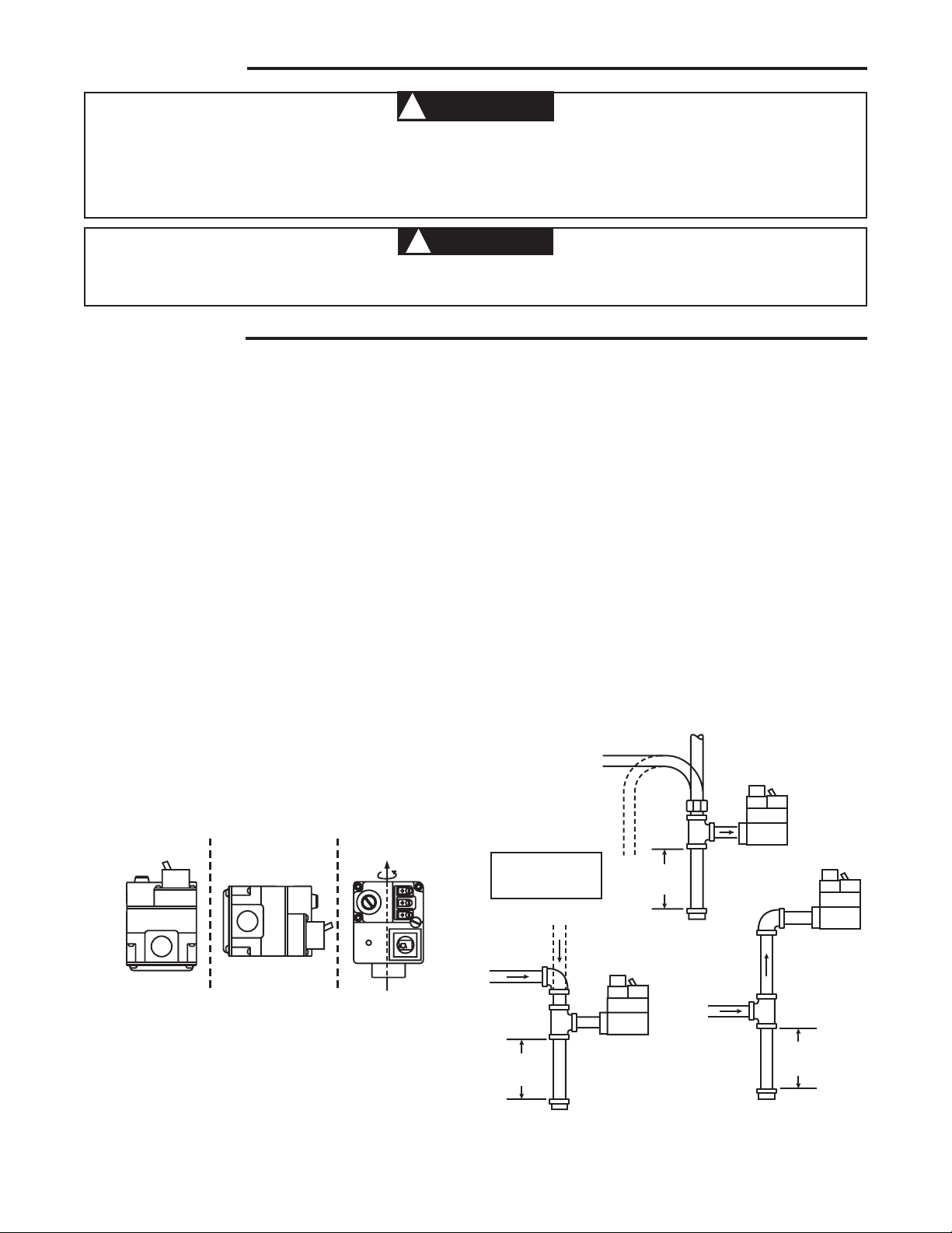
Horizontal
Drop
Piped Gas
Supply
Gas Valve
3 in.
minimum
Gas Valve
Riser
Piped Gas
Supply
3 in.
minimum
Drop
Horizontal
Riser
Gas Valve
Tubing Gas
Supply
3 in.
minimum
NOTE:
Always Include
A Drip Leg In Piping
INLET BOSS
UP OR DOWN
UPRIGHT
LEFT OR RIGHT
Upright, 90° from upright or vertical
NOTE: Control shown may not be identical
to replacement control.
1. Do not short out terminals on gas valve or primary control to test. Short or incorrect wiring can cause
equipment damage, property damage and/or personal injury.
2. This control is not intended for use in locations where it may come in direct contact with water. Suitable
protection must be provided to shield the control from exposure to water (dripping, spraying, rain, etc.).
Before beginning any modification, be sure ALL electrical disconnects are in the OFF position. TAG THE DISCONNECT SWITCHES WITH A SUITABLE WARNING LABEL. Electrical shock can cause personal injury or death.
INSTALLATION
1. Shut off power to the unit and install Lock-Out tag on all
disconnects and breakers.
2. Turn off main gas supply line valve.
3. Mark all wires going to the old valve with the terminal
description that they are attached to.
4. If replacing an existing valve, disconnect all plumbing and
electrical connections from the old control.
5. The control may be installed in any orientation except
upside down (see figure 1). The arrow on the valve indicates the direction of gas flow through the control.
6. You should use new pipe that is properly chamfered,
reamed, and free of burrs and chips. If you are using old
pipe, be sure it is clean and free of rust, scale, burrs,
chips, and old pipe joint compound.
7. Apply pipe joint compound (pipe dope) that is approved
for all gases, only to the male threads of the pipe
joints. DO NOT apply compound to the first two threads
(see figure 2 for typical piping connections).
8. Install gas valve by holding inlet boss with adjustable
wrench. Do not tighten excessively, as this may damage
the valve (Torque: 375 in-lb maximum). Do not crossthread during installation as this may damage the valve.
9. If the original gas valve has a barbed hose fitting, install
pressure tube on barbed hose fitting of the replacement
valve. Ensure that the pressure tube will not kink.
10. Do not remove barbed hose fitting from replacement valve
even if the original valve does not have it.
11. Some applications will require modification of the pilot
tube.
12. See SYSTEM WIRING when making electrical connections.
Connect wires per Fig. 3 Diagram and Fig. 4 Chart.
13. After installation is complete, check the operation of the
unit and, with main burners firing, check all joints for leaks
using a soap and water solution. Retighten all joints where
bubbles appear. DO NOT USE OPEN FLAME TO CHECK
FOR LEAKS
2
Figure 1. Mounting positions
Figure 2. Typical Gas Valve Piping
Page 3
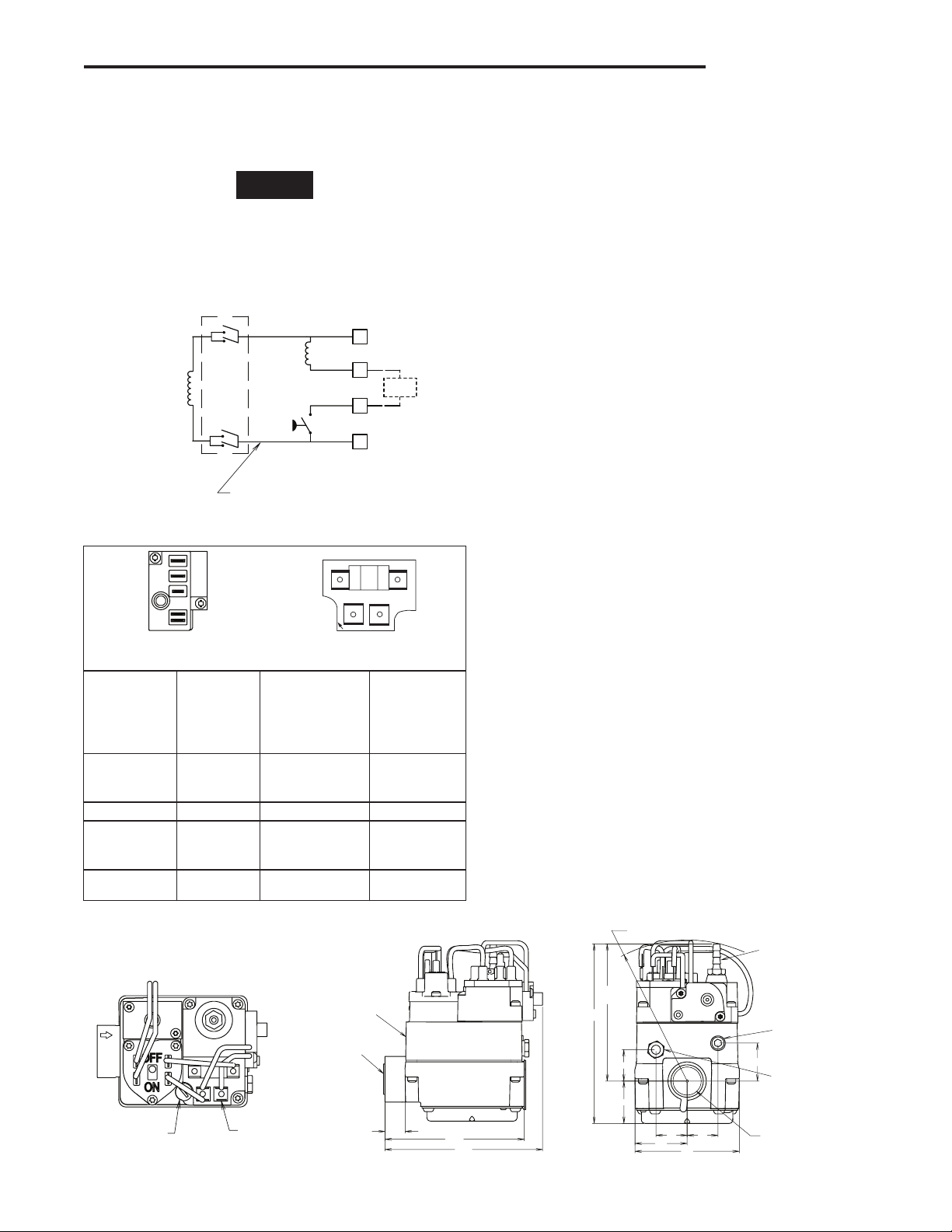
INSTALLATION
1/4” X 3/16”
TERMINAL
ADAPTER
PILOT ADJUSTING
COVER SCREW
.58
4.53
4.00
INLET 1/2"-14 N.P.T.
THDS. WITH SCREEN
INLET
1/8"-27 N.P.T.
PRESSURE TAP
4.00 R
SWING RADIUS
BARBED HOSE FITTING
MUST BE REINSTALLED
IF REGULATOR
IS READJUSTED
PRESSURE ADJUSTING
SCREW IS BENEATH
THE BARBED
HOSE FITTING
OUTLET
PRESSURE TAP
1/8”-27 N.P.T.
PILOT GAS OUTLET
CONNECTION
FOR 1/4” O.D. TUBE
OUTLET 3/4”-14 N.P.T.
THDS. WITH SCREEN
.88
1.44
2.87
1.25
5.09
3.89
REF.
.89
1.08
.88
PILOT
(REDUNDANT)
C
MAIN
PRESSURE
SWITCH
ON/OFF
SWITCH
2
1
4
3
FLAME
SWITCH
36C
ELECTRICAL SCHEMATIC
36C94-303
VALVE WIRING
1
2
3
4
PILOT ADJ.
5
1
4
3
2
NOTE
SYSTEM WIRING
REFER TO AND FOLLOW THE APPLIANCE MANUFACTURER'S WIRING DIAGRAM. REFER TO FIG. 3 FOR TERMINAL
IDENTIFICATION.
All wiring should be installed in accordance with local and national electrical codes and ordinances.
Always check that the electrical power supply used agrees with
the voltage and frequency shown on the gas control.
Figure 3. Valve Wiring
36E93
Terminal Panel
36E93-301
36E93-302
36E93-303
Description Term and Size
36E93-304
Old Terminals
Pilot
5
(Redundant)
1/4" Male Spade 3
Coil
1 Main Coil 1/4" Male Spade 1
4
2
3
Pressure
Switch
Common 1/4" Male Spade 2
1/4" Male Spade
with 1/4" x 3/16"
adapter installed
36C94
Terminal Panel
36C94-303
36C94-302
New Terminals
4
Pilot Gas Connection
Install fitting into pilot gas outlet (see Fig. 7), turning until fingertight. Insert clean, deburred tubing all the way through the fitting.
While holding the tubing securely, slowly tighten fitting until you
feel a slight "give." Tighten the fitting an additional 1-1/2 turns.
Conversion from Natural to L.P. Gas. Refer to conver-
sion kit installation instructions.
Outlet Pressure Adjustment
This control is shipped from the factory with the regulator set to
3.5" W.C. (Natural gas full flow). If required, the regulator can
be adjusted for outlet pressures normally ranging from 2.5 to
5" W.C. (natural gas) or 7.5 to 12" W.C. (L.P. gas). Do not force
the adjusting screw beyond the limits that it can easily be
adjusted.
Inlet/Outlet pressure test ports are 1/8" NPT (see Fig. 7). For
testing pressure, the outlet pressure tap plug will need to be
removed and a separate hose fitting installed. After testing pressure with a manometer remove hose fitting and re-install plug.
Tighten to 60 in-lb max.
1. Attach the manometer to the outlet pressure tap of the
valve.
2. Energize system to ignite main burner.
3. Remove barbed hose fitting.
4. To DECREASE outlet pressure, turn the adjusting screw
(beneath the barbed hose fitting) counterclockwise.
To INCREASE outlet pressure, turn the adjusting screw
clockwise.
5. Replace the barbed hose fitting. Cycle the valve two or
three times to verify regulator setting.
Pilot Gas Adjustment
This control was factory preset and will not normally require
additional adjustment of pilot flame.
If the pilot flame requires adjustment, remove the pilot adjusting
cover screw and gasket (see Fig. 5). To REDUCE pilot flame,
turn the pilot adjust screw (beneath the cover screw) clockwise.
To INCREASE pilot flame, turn the pilot adjust screw counterclockwise. Replace gasket and tighten cover screw.
Figure 4. Terminal Connection Old/New
Figure 5. Gas Valve, Top Figure 6. Gas Valve, Side Figure 7. Gas Valve, Outlet Side
3
Page 4
OPERATING INSTRUCTIONS
TO TURN OFF GAS TO APPLIANCE
FOR YOUR SAFETY READ BEFORE OPERATING
WARNING
!
If you do not follow these instructions exactly, a fire or explosion
may result causing property damage, personal injury or loss of life.
LIGHTING INSTRUCTIONS
A. This appliance is equipped with an intermittent
ignition device which automatically lights the
appliance. Do not try to light the pilot by hand.
B. BEFORE OPERATING smell all around the
appliance area for gas. Be sure to smell next to
the floor because some gas is heavier than air
and will settle on the floor.
FOR YOUR SAFETY
“WHAT TO DO IF YOU SMELL GAS”
• Donottrytolightanyappliance.
1. STOP! Read the safety information above on this
page.
2. Set the thermostat to lowest setting.
3. Turn off all electric power to the appliance.
4. This appliance is equipped with an ignition device
which automatically lights the burner. Do not try
to light the burner by hand.
5. Remove control access panel.
6. Push On/Off switch to "OFF."
7. Wait five (5) minutes to clear out any gas. If you
then smell gas, STOP! Follow “B” in the safety
• Donottouchanyelectricalswitch;donot
use any phone in your building.
• Immediatelycallyourgassupplierfroma
neighbor’s phone. Follow the gas supplier’s
instructions.
• Ifyoucannotreachyourgassupplier,call
the fire department.
C. Do not use this appliance if any part has been
under water. Immediately call a qualified service
technician to inspect the appliance and to replace
any part of the control system and any gas control
which has been under water.
information above. If you don’t smell gas, go to
the next step.
8. Push On/Off switch to “ON.”
9. Replace control access panel.
10. Turn on all electric power to the appliance.
11. Set thermostat to desired setting.
12. If the appliance will not operate, follow the
instructions “To Turn Off Gas To Appliance” and
call your service technician or gas supplier.
1. Set the thermostat to lowest setting.
2. Turn off all electric power to the appliance if service
is to be performed.
3. Remove control access panel.
4. Push On/Off switch to “OFF.”
5. Replace control access panel.
White-Rodgers is a division
of Emerson Electric Co.
The Emerson logo is a
trademark and service mark
of Emerson Electric Co.
www.white-rodgers.com
www.emersonclimate.com
 Loading...