

Page 1
CAUTION
WHITE-RODGERS
Operator: Save these instructions for future use!
FAILURE TO READ AND FOLLOW ALL INSTRUCTIONS CAREFULLY BEFORE
INSTALLING OR OPERATING THIS CONTROL COULD CAUSE PERSONAL
INJURY AND/OR PROPERTY DAMAGE.
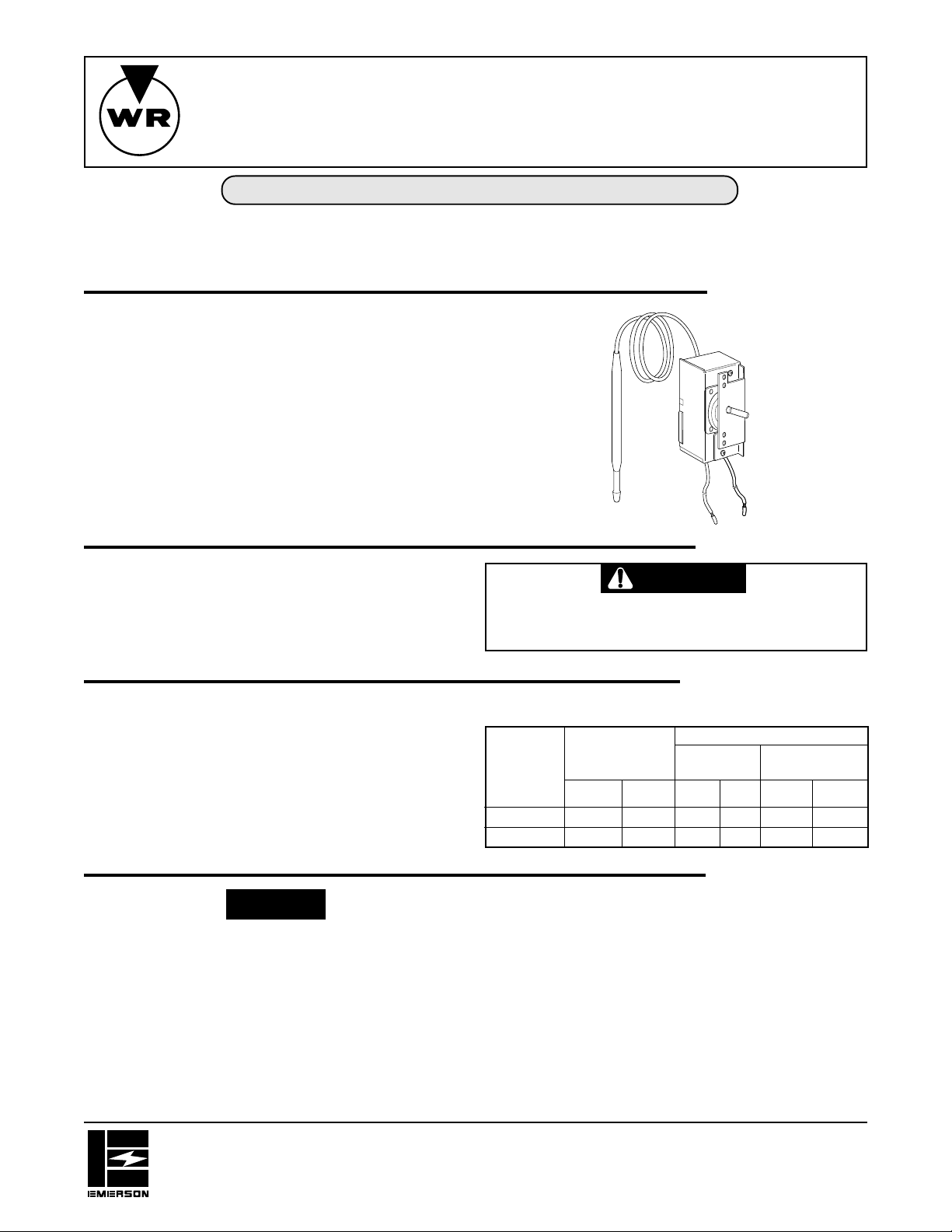
Type 2B61 and 2B62 Remote Bulb Thermostats are designed
for use on a wide variety of heating equipment and appliances,
and are especially suitable for electric heating. Extremely compact in size, these snap-action thermostats are suitable for use
on both inductive and non-inductive loads.
When the temperature of the liquid or air surrounding the bulb
rises, the switch contacts open to turn off the heat. When the
temperature drops the contacts close to turn on the heat.
TYPE 2B61 & 2B62
SNAP ACTION
REMOTE BULB THERMOSTAT
INST ALLA TION INSTRUCTIONS
DESCRIPTION
All wiring must conform to local and national electrical codes and
ordinances.
This control is a precision instrument, and should be handled
carefully. Rough handling or distorting components could cause
the control to malfunction.
Switch Action: Open on rise, snap-action
Contact Structure:
Type 2B61: – Single Pole
Type 2B62: – Double Pole
Maximum Ambient:
Temperature Switch: 150°F (66°C)
NOTE
These controls have been accurately calibrated at the factory.
Any attempt to calibrate these controls voids the White-Rodgers
warranty.
The switch mechanism of this control may be mounted in any
location, provided that the temperature and humidity of the air in
which it is located do not cause a condensation on the switch
parts.
If the equipment manufacturer has made provisions for location
of the switch and control bulb, follow his instructions. If none are
provided, the following general rules should be observed:
PRECAUTIONS
To prevent electrical shock and/or equipment damage,
disconnect electric power to system at main fuse or
circuit breaker box, until installation is complete.
SPECIFICATIONS
Electrical Rating
INDUCTIVE RATING
NON-INDUCTIVE
TYPE RATING FULL LOAD LOCKED ROTOR
NUMBER
120V 240V 120V 240V 120V 240V
2B61 25A 25A 10A 6A 60A 36A
2B61 – 25A 10A 6A 60A 36A
INSTALLATION
1. The control bulb should be located in an area of average
temperature of the medium being controlled.
When used to sense air temperature (as in an electric
heater) the bulb should be located so that the return air to the
heater flows freely over the bulb. The bulb should be fastened away from the cabinet of the heater so that it senses
air temperature, and not cabinet temperature.
When used to control a liquid bath, be sure that the bulb is
fully immersed in the liquid. Also be sure that the bulb is
located where it can sense average temperature of the liquid.
WHITE-RODGERS DIVISION
EMERSON ELECTRIC CO.
9797 REAVIS RD., ST. LOUIS, MO. 63123
(314) 577-1300, Fax (314) 577-1517
9999 HWY. 48, MARKHAM, ONT. L3P 3J3
(905) 475-4653, FAX (905) 475-4625
Printed in U.S.A.
PART NO. 37-5539A
Replaces 37-9245
9523
Page 2
INSTALLATION (CONT.)
In this regard, do not locate the bulb too close to the heating
element.
2. Care should be taken not to damage the capillary tubing
between the switch and bulb of the control. Do not kink the
capillary.
3. Do not dent or bend the control bulb as this will change the
SETTING
In most cases the equipment manufacturer has provided a dial
to indicate the setting of the control. For a warmer setting, turn
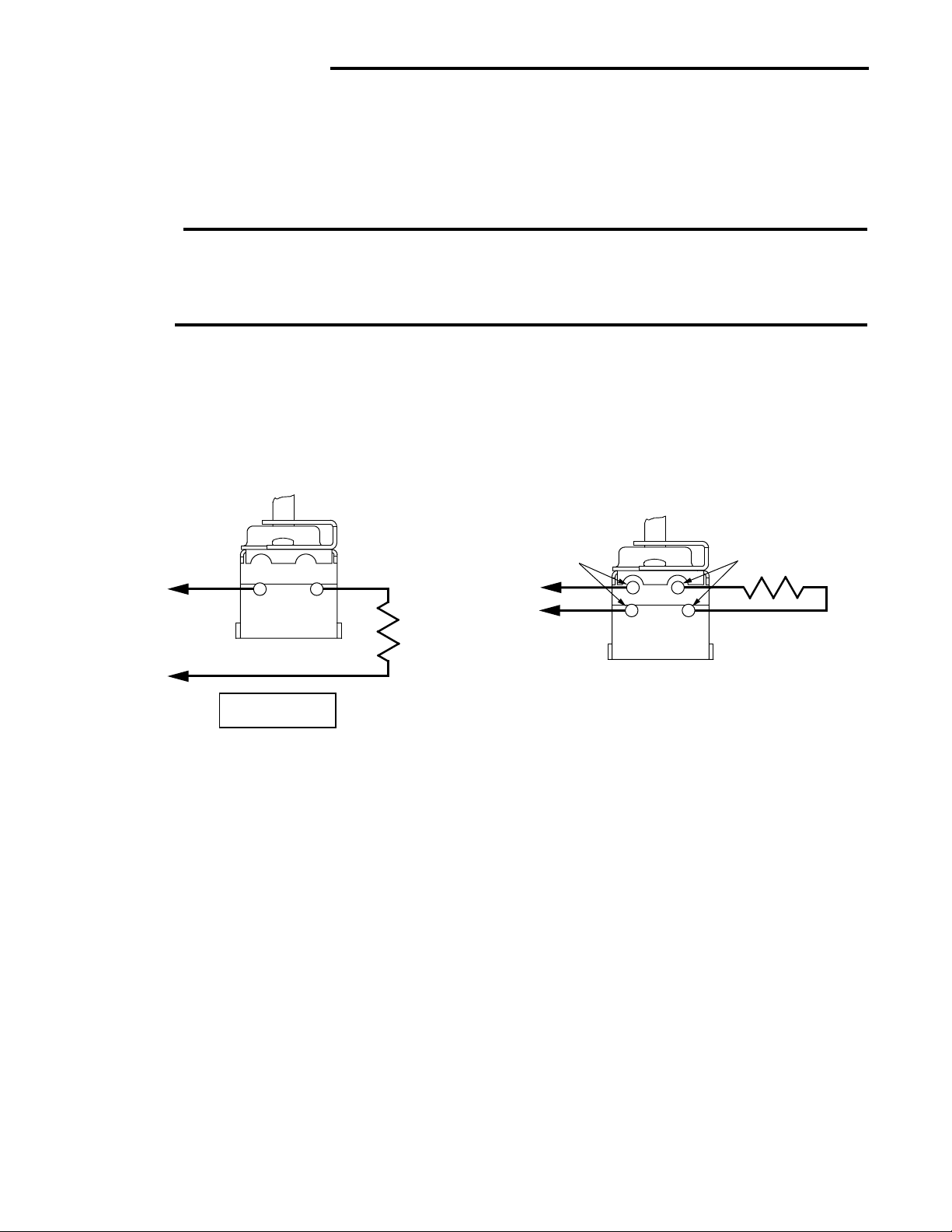
WIRING
All wiring should be done in accordance with local and national electrical codes and ordinances.
Follow any instructions provided by the equipment manufacturer.
The diagrams shown here represent typical wiring for these
controls.
control calibration and cause the control to cycle at a temperature lower than the dial setting.
4. The switch of the control may be mounted in any convenient
location provided that the ambient temperature surrounding
the switch does not exceed 150°F (66°C).
knob or shaft clockwise. For a cooler setting, turn knob or shaft
counterclockwise.
TYPE 2B62TYPE 2B61
L1
LINE
L2
MAKE L1 “HOT”
ON 120V MODELS
LOAD
BLACK (LINE)
L1
240V
L2
BLUE (LOAD)
2
Page 3

ATTENTION
WHITE-RODGERS
Utilisateur: conservez ces instructions pour vous y référer au besoin!
SI VOUS NE LISEZ PAS ATTENTIVEMENT CES INSTRUCTIONS AVANT
D’INSTALLER ET D’UTILISER LA COMMANDE, VOUS RISQUEZ DE CAUSER
DES BLESSURES ET DES DOMMAGES MATÉRIELS.
Les thermostats de type 2B61 et 2B62 avec capteur à distance
sont conçus pour commander divers types d’appareils de
chauffage et particulièrement d’appareils à l’électricité. De
dimensions réduites, ces thermostats à déclic conviennent
aussi bien aux charge inductives que non inductives.
Lorsque la température du liquide ou de l’air en contact avec le
capteur augmente, les contacts de l’interrupteur sont ouverts et
coupent le chauffage. Lorsque la température baisse, les contacts
sont fermés et font démarrer le chauffage.
THERMOSTAT À DÉCLIC
AVEC CAPTEUR À DISTANCE
TYPE 2B61 & 2B62
INSTRUCTIONS D’INSTALLATION
DESCRIPTION
Tout le câblage doit être conforme aux codes et règlements
locaux et nationaux qui régissent les installations électriques.
Cette commande est un instrument de précision qui doit être
manipulé avec soin. Elle peut se détraquer si elle est manipulée
de façon négligente ou si des composantes sont déformées.
Commutateur : Ouverture sur hause, à déclic.
Contacts :
Type 2B61 : Unipolaire;
Type 2B62 : Bipolaire.
Température ambiante maximum :
Commutateur de température : 66°C (150°F)
NOTE
La commande a été étalonnée avec précision à l’usine. Toute
tentative d’étalonnage de la commande annulera la garantie de
White-Rodgers.
Le commutateur de la commande peut être installé n’importe où,
tant que les conditions de température et d’humidité du lieu
n’entraînent pas la formation de condensation sur les composantes du commutateur.
Si le fabricant de l’équipement recommande un emplacement
pour la commande et le capteur, alors veuillez en tenir compte.
Dans le cas contraire, veuillez vous fier aux règle générales qui
suivent :
PRÉCAUTIONS
Pour prévenir les risques de chocs électriques et de
dommages matériels, coupez l’alimentation du système au panneau de distribution électrique principal
pendant toute la durée de l’installation.
SPÉCIFICATIONS
Charges électriques :
CHARGE INDUCTIVE
CHARGE NON PLEINE ROTOR
NO DE INDUCTIVE CHARGE BLOQUÉ
TYPE
120 V 240 V 120 V 240 V 120 V 240 V
2B61 25A 25 A 10 A 6 A 60 A 36 A
2B61 — 25A 10A 6A 60A 36A
INSTALLATION
1. Le capteur doit être placé dans un endroit où il sera exposé
à la température moyenne du milieu à commander.
S’il est utilisé pour détecter la température de l’air (comme
dans un appareil de chauffage électrique), le capteur doit
être placé de façon à assurer que l’air repris qui pénètre
dans l’appareil puisse circuler tout autour. Le capteur doit
être orienté à l’écart du boîtier afin d’assurer qu’il détecte la
température de l’air et non celle du boîtier.
S’il est utilisé pour détecter la température d’un bain
liquide, assurez-vous que le capteur est complètement
immergé. Assurez-vous aussi qu’il sera exposé à la
température moyenne du liquide.
WHITE-RODGERS DIVISION
EMERSON ELECTRIC CO.
9797 REAVIS RD., ST. LOUIS, MO. 63123
(314) 577-1300, Télécopieur (314) 577-1517
9999 HWY. 48, MARKHAM, ONT. L3P 3J3
(905) 475-4653, Télécopieur (905) 475-4625
Imprimé aux États-Unis
PIÈCE NO 37-5539A
Remplace 37-9245
9523
Page 4

INSTALLATION (suite)
Ainsi, prenez soin de ne pas placer le capteur trop près de
l’élément chauffant.
2. Prenez soin de ne pas endommager le tube capillaire qui
relie la commande au capteur. Évitez de pincer ou de plier
le capillaire.
3. Éviter d’écraser ou de déformer le capteur, car l’étalonnage
de la commande en serait modifié. Les cycles de marche de
RÉGLAGE
la commande prendraient alors place à une température
inférieure au point de consigne.
4. Le commutateur de la commande peut être installé dans
n’importe quel lieu pratique où la température ambiante ne
dépasse pas 66°C (150°F).
Dans la plupart des cas, le fabricant de l’équipement fournit un
cadran qui permet de régler le point de consigne de la commande.
Pour un hausser le point de consigne, tournez le bouton ou la
tige à droite; pour le baisser, tournez à gauche.
CÂBLAGE
Tout le câblage doit être conforme aux codes et règlements locaux et nationaux qui régissent les installations électriques.
Référez-vous aux directives fournies par le fabricant de
l’équipement.
Les schémas ci-dessous représentent le câblage typique des
commandes.
TYPE 2B62TYPE 2B61
BLEU (CHARGE)NOIR (RÉSEAU)
L1
RÉSEAU
CHARGE
L1
240 V
L2
L2
MODÈLES DE 120 V :
L1 DOIT ÊTRE « SOUS TENSION »
2
 Loading...