

Page 1
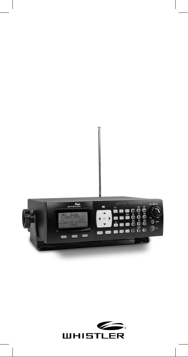
DIGITAL TRUNKING
Desktop/Mobile
Radio Scanner
OWNER’S MANUAL
WS1065
Page 2

TABLE OF CONTENTS
Contents
Introduction ................................................... 4
What is Object Oriented Scanning? ............................. 4
Package Contents ...................................................... 5
Scanning Legally ......................................................... 5
Features ...................................................................... 6
Setup ............................................................. 7
Antenna ...................................................................... 7
External Antenna ........................................................ 8
Desktop Operation ..................................................... 9
Mount Installation ....................................................... 9
Headphones and Speakers ....................................... 10
Listening Safely ......................................................... 10
AC Adapter ............................................................ 11
DC Power Cable ....................................................... 12
Understanding the Keypad ...................................... 13
Turning on the Scanner ............................................ 15
Understanding the Display Icons ............................. 16
Programming .............................................. 17
Programming Cables ................................................ 17
RadioReference.com ................................... 18
Scanner Cloning ....................................................... 19
Text Entry .................................................................. 21
Scanning ...................................................... 23
Objects and Scan Lists ............................................. 23
Monitoring ............................................................... 25
Scanning .................................................................. 27
Priority Scan ............................................................. 29
Favorites Scan List ................................................... 30
Object Lockout ........................................................ 31
Multi-Site Mode (Motorola and P25) ....................... 33
Home Repeater AutoMove (LTR) ............................. 34
2
Page 3

TABLE OF CONTENTS
Searching ...................................................... 35
Limit Search Object (LMIT) ........................................37
Service Search Object (SRVC) ...................................39
Spectrum Sweeper Object (SWPR) ...........................41
Weather Features .........................................43
SAME Standby .......................................................... 43
Configuring ..................................................46
Using V-Scanner Storage ..........................................49
Initializing Global Settings ........................................51
Initializing to Factory Defaults...................................52
Configuration Shortcuts ............................................ 53
Manual Programming Guide ........................54
Conventional Objects (CONV) .................................. 55
Trunking System (TSYS) Object ................................ 57
Talkgroup (TGRP) Object ..........................................59
Duplicating Objects .................................................. 61
No Scan List .............................................................. 61
Deleting Objects ....................................................... 62
Memory Usage .......................................................... 62
Hit Counter ..............................................................63
Specifications ..............................................64
Frequency Coverage ................................................67
Maintenance ................................................. 68
Birdie Frequencies ....................................................68
PC Interface ................................................. 69
FCC Statement .........................................................71
Limited Warranty .......................................................72
3
Page 4

INTRODUCTION
WELCOME
Thank you for choosing a Whistler product. We are
dedicated to providing products that represent both
quality and value. Please read the user manual carefully
before using this product. If you have additional
questions, please visit the FAQ page on our website at
www.whistlergroup.com or call toll free 800-531-0004,
8am to 5pm CT, Monday through Friday to speak to a
Customer Service Representative.
Introduction
Scanning technology has changed dramatically over
the years. The WS1065 scanner with Object Oriented
User Interface is designed to help the hobbyist build a
collection of channels to scan:
• Start small and expand
• Organize channels and talkgroups
• Remove unwanted channels and talkgroups
What is Object Oriented Scanning?
Programming scanning receivers can be challenging,
but object-oriented programming simplifies the
process by using common conventions for scanning
concepts that have common characteristics.
A Scannable Object is any defined item that can be
scanned or monitored, including:
• Conventional, non-trunked radio frequencies
• Talkgroups used on a trunked radio system
• Radio services
• Defined searches
Because scannable objects are defined by the same
basic elements, the Object Oriented User Interface
(OOUI) is designed to simplify scanning by managing
all scannable objects similarly. When you learn how to
program one type of object, you can program other
types of scannable objects as well.
4
Page 5

SCANNING LEGALLY
Package Contents
• Scanner
• Antenna
• PC/IF Cable
• AC adapter
• DC cable with fuse
• Screws (2)
• Mounting bracket
• DIN sleeve
• Keys (2)
• Rubber washers (2)
• Lock washers (2)
• Rubber feet (5)
• Knobs (2)
• User’s Guide
• QuickStart Guide
Scanning Legally
Your scanner covers frequencies used by many
different groups including police and fire departments,
ambulance services, government agencies, private
companies, amateur radio services, military operations,
pager services, and wireline (telephone and telegraph)
service providers. It is legal to listen to almost every
transmission your scanner can receive. However, there
are some transmissions you should never intentionally
listen to.
These include:
• Telephone conversations (cellular, cordless, or other
means of private telephone signal transmission)
• Paging transmissions
• Any intentionally decoded scrambled or encrypted
transmissions
According to the Electronic Communications Privacy
Act (ECPA), you are subject to fines and possible
imprisonment for intentionally listening to, using, or
divulging the contents of such a transmission unless
you have the consent of a party to the communication
(unless such activity is otherwise illegal). This scanner
has been designed to prevent reception of illegal
transmissions. This is done to comply with the
legal requirement that scanners be manufactured
5
Page 6

FEATURES
so as to not be easily modifiable to pick up those
transmissions.
Do not open your scanner’s case to make any
modifications that could allow it to pick up
transmissions that are illegal to monitor. Doing so
could subject you to legal penalties. We encourage
responsible, legal scanner use. In some areas, mobile
use of this scanner is unlawful or requires a permit.
Check the laws in your area. It is also illegal in many
areas to interfere with the duties of public safety
officials by traveling to the scene of an incident
without authorization.
Features
• Intuitive Object Oriented User Interface
• Context Sensitive Help
• Scan List
• V-Scanner Technology - Save complete backup radio
configurations, up to 21 versions.
• SKYWARN™ Storm Spotter Function
• SAME and All Hazards Weather Alerting
• Multi-System Trunking
• Exclusive Automatic Adaptive Digital Tracking - Adapts to
multipath or fading for P25 digital systems
• Exclusive Digital AGC
• LTR Home Repeater AutoMove
• Subaudible Squelch Decoder
• Spectrum Sweeper – Advanced feature for finding active
frequencies.
• Zeromatic – Enhances the scanner’s ability to lock on to
the actual center frequency of a search hit instead of an
adjacent frequency.
• P25 NAC Functionality
• Alert LED and Audible alarms
• High Speed USB PC Interface
• Real-time Signal Strength Indicator
• Upgradeable CPU and DSP Firmware
6
Page 7
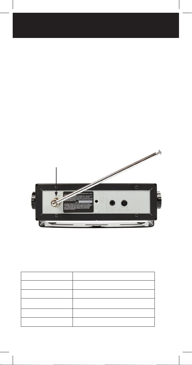
INSTALLATION OF ANTENNA
Setup
Antenna
You scanner's antenna connects easily, or you can
use a variety of antennas, such as an external mobile
antenna or outdoor base station antenna.
To connect an external antenna, follow the
installation instructions supplied with the antenna.
Always use 50-ohm coaxial cable, such as RG-58 or
RG-8 low-loss dielectric coaxial cable. You may also
need a BNC adapter.
1. Align the slots.
2. Rotate connector.
To connect the included antenna:
Your scanner’s frequency sensitivity depends on its
location and the antenna length. For best reception,
adjust the antenna’s length as follows:
FREQUNCY ANTENNA LENGTH
25-54 MHz Extend fully
108-174 MHz Extend 4 segments
216-225 MHz Extend 3 segments
225-406 MHz Extend 2 segments
406-1300 MHz Collapse fully
7
Page 8

INSTALLATION OF ANTENNA
WARNING: Use extreme caution when installing or
removing an outdoor antenna. If the antenna starts to
fall, let it go! It could contact overhead power lines. If
the antenna touches a power line, touching the antenna,
mast, cable, or guy wires can cause electrocution and
death. Call the power company to remove the antenna.
DO NOT attempt to do so yourself.
WARNING: Outdoor antennas must be properly
grounded to prevent static buildup and lightning
damage. Article 810 of the National Electrical Code,
ANSI/NFPA 70, provides information about proper
grounding of the antenna mast, connection of coaxial
cable to an lightning arrestor, size of grounding
conductors, location of the lightning arrestor and
connection of grounding conductors to grounding
electrodes.
Additionally, disconnect your radio from the outdoor
antenna during electrical storm activity to prevent
damage. The diagram below provides an example of a
proper antenna grounding system.
8
Page 9

DESKTOP OPERATION
Desktop Operation
The mounting bracket works as a desktop stand when
attached underneath the radio. Use the provided rubber
feet to prevent sliding or scratching. Do not use the
rubber feet if mounting permanently to a fixed surface.
Extra pads are provided for additional stability.
1. Attach the adhesive rubber feet to the mounting
bracket.
2. Attach the two adhesive rubber washers over the
mounting holes, between the mounting bracket
sides and the scanner’s side holes.
3. Position the bracket with the two recessed fee
toward the front of the scanner.
4. Use the two provided knobs to secure the scanner
within the mounting bracket.
Mount Installation
Attach the bracket over the radio to suspend the
scanner from above. Attach the bracket underneath
the scanner to mount it on top of a flat surface. Your
WS1065 also fits into the included DIN-E compatible
sleeve for existing dashboard openings.
NOTE: In some cases, installation requires specialized
tools and skills. If in doubt, seek assistance from a local
car audio electronics installation shop, or a local twoway radio dealer.
Select a location that does not interfere with driving or
with the deployment of your vehicle’s air bags. Do not
mount this or any other equipment where deployment
of the air bags might cause it to be propelled towards
passengers. If necessary, seek advice from your
automotive dealer or service shop.
9
Page 10

ACCESSORIES
Use the mounting bracket as a template to mark the
locations for the two mounting screws.
Drill holes that are slightly smaller than the screws. Use
caution not to damage wiring or components that are
located behind the mounting surface.
Using the provided screws and lock washers, attach
the mounting bracket to your vehicle.
Headphones and Speakers
You can plug headphones (not supplied) or an
amplified speaker (not supplied) with a 1/8-inch (3.5
mm) mini-plug earphone or in the headphone jack on
top of your scanner. This automatically disconnects the
internal speaker.
NOTE: Use an amplified speaker with this scanner;
Non-amplified speakers do not provide sufficient
volume for comfortable listening.
Listening Safely
To protect your hearing, follow these guidelines when
you use headphones:
Set the volume to zero before putting on headphones.
With the headphones on, adjust the volume to a
comfortable level.
Avoid increasing the volume after you set it. Over
time, your sensitivity to a volume level decreases, so
volume levels that do not cause discomfort might
damage your hearing.
Avoid or limit listening at high-volume levels.
Prolonged exposure to high-volume levels can cause
permanent hearing loss.
Wearing headphones while operating a motor vehicle can
create a traffic hazard and is illegal in most areas. Even
though some headphones let you hear some outside
sounds when listening at normal volume levels, they still
can present a traffic hazard. Exercise extreme caution!
10
Page 11

EXTERNAL POWER
AC Adapter
You must use a power source that supplies 12-14.4
VDC and is rated for 600 mA. Its center tip must be
set to positive and its plug must fit the scanner’s DC
13.8V jack. The supplied DC power adapter meets
these specifications. Using a DC adapter that does
not meet these specifications could damage the
scanner or the adapter.
To Connect the AC Adapter
1. Plug the supplied AC adapter into the DC 13.8V
jack.
2. Plug the AC adapter into your wall outlet.
WARNING: To prevent electric shock, do not use the
AC adapter’s polarized plug with an extension cord,
receptacle, or other outlet unless you can fully insert
the blades to prevent blade exposure.
11
Page 12

EXTERNAL POWER
DC Power Cable
Connect the supplied DC power cable to a vehicle
power source:
1. Disconnect your battery's negative (-) terminal.
NOTE: Disconnecting your battery may reset some
devices in your vehicle, such as automotive audio
systems, navigation systems, or alarm systems.
2. Route the suppled DC power cord between a
power source and the mounting location for your
scanner.
3. Ground the power cord's black wire to your
vehicle’s chassis.
NOTE: The grounding screw must make complete
contact with the metal frame of your vehicle.
4. Connect the power cord's red wire to a voltage
source that turns on and off with the ignition
switch, such as a spare accessory terminal in your
vehicle’s fuse box.
5. Insert the power plug into the DC power jack on
the rear of the radio.
6. Reconnect the cable to the negative (-) terminal of
your vehicle’s battery.
NOTE: If your vehicle’s engine is running, you might
hear electrical noise from the engine while scanning.
This is normal.
WARNING: The DC power cord is equipped with an
inline fuse. This fuse protects your scanner and your
vehicle from damage in case of equipment malfunction
or a short circuit. Do not remove the inline fuse holder
from the DC power cord. If the fuse blows, replace
it with a 2A fuse and apply power again. If the fuse
blows again, check all wiring for short circuits, and
check the radio for a malfunction.
12
Page 13
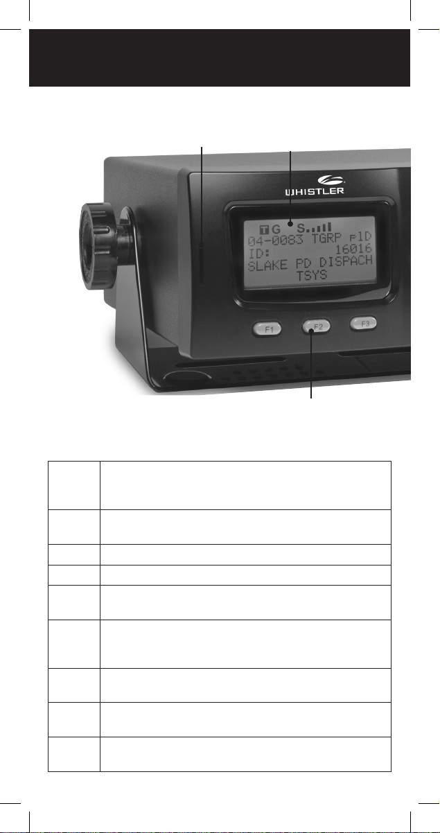
KEYPAD
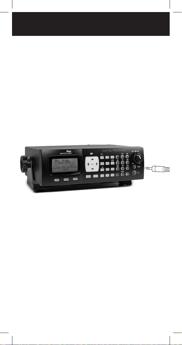
Understanding the Keypad
DIN Keyslot
LCD Display
Softkeys
Your WS1065 features an easy-to understand backlit
keypad.
F1
Referred to as "softkeys;" These keys activate
F2
functions currently displayed immediately above
F3
them.
FUNC
DIM
MAN
SCAN
TUNE
SRCH
ATT
Function. Press and release the FUNC key first,
and then press the next key.
Backlight, (FUNC+ DIM locks the keypad)
Manual Mode monitors single objects.
Scan Mode, (FUNC + SCAN launches Spectrum
Sweeper)
Direct tuning of any valid frequency,
(FUNC + TUNE loads the most recently scanned
frequency)
Search Mode for service and conventional
frequencies
Attenuator On/Off, (FUNC + ATT sets Global
Attenuator On/Off)
PRI
Priority setting for current object, (FUNC + PRI
Sets Priority Mode On/Off)
13
Page 14
Alert LED
Four-direction
keypad
KEYPAD
Squelch Control
Operations
Keys
Volume Control
PC/IF
Headphone
Connector
Jack
FAV
PROG
L/OUT
ENT
PAUSE
Favorites Scan Mode, FUNC + FAV adds the
current object to the Favorites Scan List.
WX
Weather scan, (FUNC + WX activates Skywarn)
Program objects, (FUNC + PROG accesses
V-Scanner)
Temporary Lockout (FUNC + L/OUT permanent
lockout).
Enter
Pauses Scanning
Scroll
Change
Setting
Four-direction keypad – Used to navigate through
objects and menu items. For some menu items, the
side buttons can be used to change settings. Press
SEL to select the highlighted item.
14
Page 15

TURNING ON SCANNER
Turning on the Scanner
The squelch and attenuator control scanner sensitivity.
If squelch is set too low, the scanner may stop on
noise or silence.
Note: Make sure the scanner’s antenna is connected
before you turn it on.
1. Turn the SQUELCH knob to about mid-position.
2. Turn the VOLUME knob to turn on the radio.
3. Turn SQUELCH down (counterclockwise) until you
hear noise.
4. Turn SQUELCH up (clockwise) a little past where
the noise stops. The higher the squelch is set, the
stronger the signal required to break the squelch.
15
Page 16

DISPLAY
Understanding the Display Icons
Your WS1065 features a high contrast, backlit Liquid
Crystal Display (LCD).
T
G
F
Srch Limit ZD
FM 154.935000
154.00 155.00
FrL/O Mode Stor
The scanner uses the following top row of icons:
The Function Key ( FUNC) has been
F
pressed. This acts as a “Shift” key.
The scanner is currently receiving trunking
T
control channel data.
The attenuator is set for Global mode.
G
The attenuator is currently active.
A
A
S
The radio’s squelch circuit is open.
S
Signal meter indicating signal strength.
Indicate scan or search direction.
16
Page 17
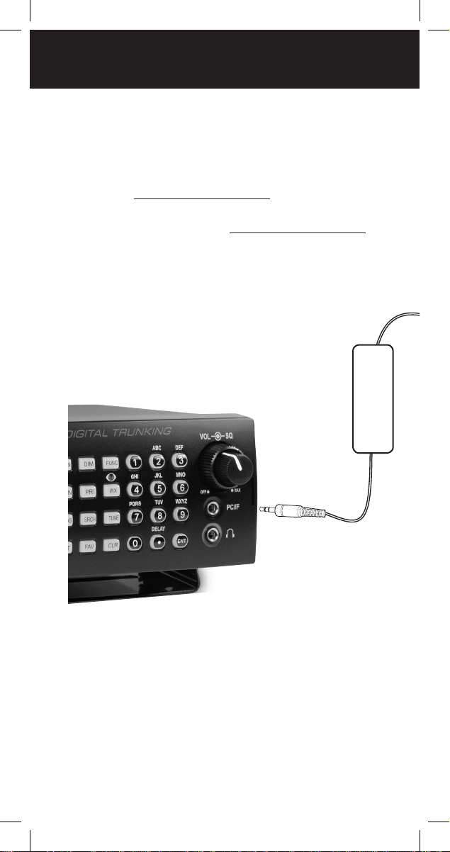
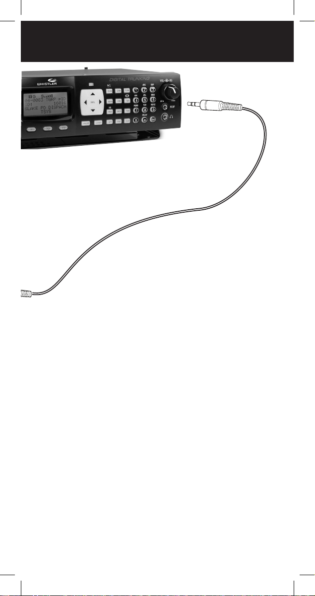
PROGRAMMING CABLES
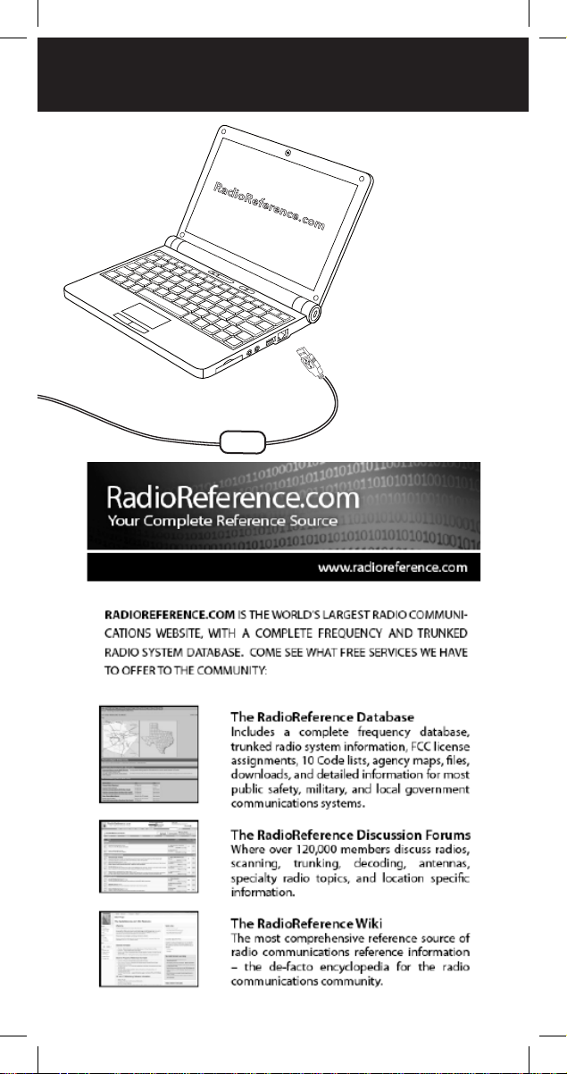
Programming Cables
The simplest method for programming a new
scanner is using a PC/IF cable, which is included
with the scanner. The cable lets you use software
provided by RadioReference.com and their
constantly updated database to program your new
scanner quickly and easily. RadioReference.com also
provides a range of resources to help improve your
overall scanning experience.
17
Page 18
RADIO REFERENCE
RadioReference.com
18
Page 19
CLONING
Scanner Cloning
If you have access to a compatible scanner that is
already programmed for your area, you can transfer
that scanner's programming using a standard stereo
patch cord (not included), terminated with 1/8” male
stereo plugs at each end.
The WS1065 is compatible with the following scanner
models: PRO-106, PRO-197, PRO-651, PRO-652, GRE
PSR-500, PSR-600, Whistler WS1040 and WS1065.
To clone a scanner:
1. Connect the two scanners at their PC/IF ports.
2. Turn on both scanners.
3. On the source scanner, press PROG.
4. Press the GLOB softkey.
5. Use the 4-direction keypad to locate the Clone
Send option.
6. Press SEL to transfer data.
19
Page 20
MANUAL PROGRAMMING
NOTE: Working memory and global settings are
transferred but not V-Scanner folders. The target
scanner's working memory will be overwritten.
In some cases, the CCDump output may interfere with
cloning.
To turn off CCDump:
1. Press PROG.
2. Press FUNC and then the GLOB softkey.
3. Use the 4-direction keypad to locate the CCDump
option and change the setting.
4. Press the Save softkey.
Manual Programming
Modern radio systems can be complex and
challenging to program. If you choose to program your
scanner manually, refer to the "Manual Programming
Guide" on page 54.
20
Page 21
TEXT ENTRY
Text Entry
Your scanner uses several text parameters, such as the
tags that identify objects.
To enter a letter in a text field,
press the number key below
the letter, then press the
number key that corresponds
with the position of the letter.
For example: K = 5 2
Uppercase is the default; use the FUNC key as a shift
key to type lowercase letters. For punctuation, refer to
the following list.
Char Press Char Press Char Press Char Press
A 21 a 2 (F) 1 1 11 $ 01
B 22 b 2 (F) 2 2 12 % 02
C 23 c 2 (F) 3 3 13 ! 03
D 31 d 3 (F) 1 4 14 ^ 04
E 32 e 3 (F) 2 5 15 ( 05
F 33 f 3 (F) 3 6 16 ) 06
G 41 g 4 (F) 1 7 17 ? 07
H 42 h 4 (F) 2 8 18 -> 08
I 43 i 4 (F) 3 9 19 ‘ 09
J 51 j 5 (F) 1 0 10 <- 00
K 52 k 5 (F) 2 . 0(F)1
L 53 l 5 (F) 3 - 0(F)2
M 61 m 6 (F) 1 # 0(F)3
N 62 n 6 (F) 2 _ 0(F)4
O 63 o 6 (F) 3 @ 0(F)5
P 71 p 7 (F) 1 + 0(F)6
Q 72 q 7 (F) 2 * 0(F)7
R 73 r 7 (F) 3 & 0(F)8
S 74 s 7 (F) 4 / 0(F)9
T 81 t 8 (F) 1 , 0(F)0
U 82 u 8 (F) 2
V 83 v 8 (F) 3
W 91 w 9 (F) 1
X 92 x 9 (F) 2
Y 93 y 9 (F) 3
Z 94 z 9 (F) 4
Letter
Position
Letter
Key
21
Page 22

QUICK TEXT
Use the 4-direction keypad to move the cursor. Press
FUNC and the 4-direction keypad to move the cursor
to the beginning or end of the field.
Use CLR as a backspace key, or press FUNC and then
CLR to clear the entire field.
QuickText
You can store up to 10 commonly used QuickText
phrases for later use in text fields. Your scanner
provides some common QuickText words, which you
can keep or edit.
To edit QuickText:
1. Press PROG.
2. Press the GLOB softkey.
3. Scroll to one of the QTXT items.
4. Press to edit the QTXT entry.
5. Edit the text. To keep the cursor at the end of your
quick text insert a dollar sign ($).
6. Press the DONE softkey.
7. Press the SAVE softkey.
To insert QuickText:
1. Position the cursor in the text field.
2. Press the QTXT softkey. The available QuickText
phrases appear.
3. Use the 4-direction keypad to select a phrase and
press SEL. (Shortcut: You may press the number
that corresponds to the QuickText item).
22
Page 23

SCANNING
Scanning
Objects and Scan Lists
Instead of channels and banks, scannable objects are
assigned Object IDs and assigned to scan lists. The
number of objects that can be grouped in a particular
scan list is not limited, and objects can be assigned to
multiple scan lists.
When programmed, your scanner provides two basic
functions for scanning radio transmissions:
• Monitoring – Listening to a single object.
• Scanning – Checking multiple saved objects,
stopping when a transmission is detected.
Additionally, you can combine different object types in
any scan list, including a mix of trunked talkgroups and
conventional frequencies. By default, every new object
you create is mapped to Scan List 01.
NOTE: Objects are not moved into scan list(s). Instead,
objects are mapped to scan lists, so that a single
object can be assigned to multiple scan lists without
using any additional scanner memory.
Your scanner provides 20 standard scan lists, one
Favorites scan list, and a Skywarn scan list.
TIP: Consider how you plan to organize your objects
for scanning. You can organize your scan lists
geographically, assigning objects for your location in
one list and objects for other locations in different lists.
You can organize your scan lists by trunking system,
assigning TGRP objects associated with specific trunked
radio systems to separate lists. You can also organize
your scan lists by object type, assigning CONV objects
to one list and TGRP objects to another.
23
Page 24

SCAN LIST
To name your scan lists:
1. Press PROG.
2. Press the GLOB softkey.
3. Scroll to Scan Lists.
4. Press SEL. The Scan Lists sub menu appears.
5. Scroll to the Scan List and press the key.
6. Scroll to the Tag field and press the key.
7. Edit the Tag text field.
8. Press the Done softkey.
9. Press the Save softkey.
10. Press the Save softkey again.
To assign objects to Scan Lists:
1. Open the object and locate the Scan Lists
parameter.
2. Press SEL to toggle membership for that scan
list. An asterisk (*) next to the scan list number
indicates assignment.
3. Press the Save softkey.
To change the default Scan List:
1. Press PROG.
2. Press the GLOB softkey.
3. Scroll down to Dflt ScanList.
4. Press SEL.
5. Enter a new default scan list number:
• 00 – Not scanned (NS)
• 01-20 – Standard Scan Lists
• 21 – The Favorites Scan List
• 22 – The SKYWARN Scan List
6. Press the Done softkey.
7. Press the SAVE softkey.
24
Page 25

MONITORING
Monitoring
Your scanner can monitor a single frequency or object.
To tune a frequency to monitor:
1. Press TUNE.
2. Press the MODE softkey to change the receive
mode (AM, FM, au).
3. Use the number keys to enter a frequency.
4. Press ENT to make this the TUNE frequency. Next
time you press TUNE, this frequency will load.
To monitor an object:
1. Press MAN to enter Manual mode.
Objects
Scan
Lists
2. Use the 4-direction keypad to browse the objects
in the current scan List and select an object to
monitor. Only scan lists that contain objects appear
when browsing.
Finding Stored Objects
The radio searches in the frequency, tag, or ID fields.
When the scanner finds a matching object, you may
press MAN to begin monitoring the object.
To find objects that are locked out:
1. Press PROG.
2. Press the EDIT softkey.
3. Press the FIND softkey.
4. Press the L/Out softkey.
5. Press the NEXT softkey to find the next locked out
object.
25
Page 26

STORED OBJECTS
To find objects by text string:
1. Press PGM.
2. Press the EDIT softkey.
3. Press the FIND softkey.
4. Press the Text softkey and enter the text string.
4a. Press the Qtxt softkey to use QuickText. Press
the to select one of the 10 Qtxt options. Press
SEL to accept Qtxt selection.
5. Use the 4-direction keypad to scroll through
available objects.
6. Press the OK softkey. Press the Exit softkey to
cancel the Find operation.
To find objects by object type:
1. Press PROG.
2. Press the EDIT softkey.
3. Use the 4-direction keypad to scroll to the filter
softkeys: CONV, TGRP, TSYS, SRCH, and SWPR.
4. Press the softkey for the object type.
5. Use the 4-directional keypad to scroll through
available objects.
26
Page 27

SCAN OBJECTS
Scanning
When scanning, the radio checks programmed
scannable objects for transmissions, stopping when
transmissions are received.
You can use lock out functions to skip specific objects,
and you can make entire scan lists active or inactive.
To scan objects:
1. Press SCAN. The two rows under Scanning
represent your scanner's scan lists (Top row = scan
lists 1-10, bottom row = scan lists 11-20).
G
Scanning
1 . 3 . . . 7 . . . pri
. . . . . . . . . .
2. Numbers represent active scan lists, periods
represent inactive scan lists. To toggle a list, press
the corresponding number on the keypad. For
11-20, press FUNC and then the second number
(FUNC + 3 = 13).
When the scanner recieves a transmission, the
object infomation apears on the screen.
Scan List
Object ID
T
04-0237 CONV plD
FM 153.950000
FIRE CT:127.3
S
3. To pause the scanner on an active object, press
PAUSE.
4. Press PAUSE or SCAN to resume scanning.
27
Page 28

SCAN LISTS FROM GLOBAL SETTINGS
To enable Scan Lists from Global Settings:
1. Press PROG to enter Program Mode
2. Press the GLOB softkey.
3. Scroll to the Scan Lists parameter and press SEL.
4. Use the 4-direction keypad to toggle the scan list.
An asterisk (*) indicates that the scan list is enabled.
5. Use or to access the Enabled option
6. Use or to enable selected scan list.
7. Press the SAVE softkey.
8. Press SAVE again.
28
Page 29

PRIORITY SCAN
Priority Scan
Priority Off
G
Scanning
1 . 3 . . . 7 . . . pri
. . . . . . . . . .
Priority On
G
Scanning
1 . 3 . . . 7 . . . PRI
. . . . . . . . . .
You can designate increased priority to certain objects:
• CONV – The scanner samples objects for activity
more frequently.
• TGRP – The scanner checks the priority object first
and during reply delays of non-priority objects.
To set priority for objects:
• While scanning, when the scanner stops for a
transmission, press PRI.
Note: plD will change to PlD indicating priority is set.
• In Manual or Program modes, browse to the object
and then press PRI.
Note: plD will change to PlD indicating priority is set.
• You can edit an object's Priority setting directly
during programming.
To activate Priority Scan Mode:
While the radio is scanning, press FUNC and then
press PRI. Repeat to cancel Priority Scan Mode.
NOTE: Priority sampling may cause brief muting of
received audio if another object is active.
29
Page 30

FAVORITES SCAN LIST
Favorites Scan List
To add an object to the Favorites Scan List, press
FUNC and then FAV while the object is active.
When you press FAV later, your scanner suspends all
scanning except for the Favorites Scan List.
To clear the entire FAV Scan List:
1. Press PROG.
2. Press the GLOB softkey.
3. Scroll to down to the Clear FAV menu item.
4. Press SEL. You will be asked to confirm the action.
5. Press the Save softkey.
30
Page 31

OBJECT LOCKOUT
Object Lockout
Transmissions for locked out objects are ignored for all
scan list. Four lockout types are available:
• Temporary – The object is locked out until the
scanner is turned off. When the scanner is turned on
again, temporary lockouts are removed. A flashing
lowercase “l” indicates a temporary lockout.
• Permanent – The object is locked out until you
unlock it. An uppercase “L” indicates a permanent
lockout.
• Talkgroup Lockout – Used with wildcard TGRP
objects. This locks out a specific talkgroup, but the
wildcard TGRP remains active.
• Search Lockout – Lock out up to 250 undesired
frequencies that are found during searches.
To lock out an object:
• While the object is active, press L/OUT.
• To apply permanent lockout, press FUNC and then
L/OUT.
• To lock out a talkgroup, press the TGL/O softkey.
Temporary
Lockout
G
04-0237 CONV plD
FM 153.950000
FIRE CT:127.3
Permanent
Lockout
G
04-0237 CONV pLD
FM 153.950000
FIRE CT:127.3
31
Page 32

OBJECT LOCKOUT
To remove a lockout:
1. Navigate to the object using the 4-direction
keypad.
2. Press L/OUT.
3. To remove a permanent lockout, press FUNC and
then L/OUT.
To find objects that are locked out:
1. Press PROG.
2. Press the EDIT softkey.
3. Press the FIND softkey.
4. Press the L/Out softkey.
5. Press the NEXT softkey to find the next locked out
object.
To edit the Search Lockout List:
1. Press PROG
2. Press the GLOB softkey
3. Scroll down to SRCH L/Outs and press SEL.
4. To manually add to the list, scroll to an empty spot
and enter the frequency.
5. To remove a frequency, press the Del softkey.
6. To clear the entire list, press FUNC and then the
Del softkey.
32
Page 33

MULTI-SITE MODE
Multi-Site Mode (Motorola and P25)
Some Motorola and P25 system sites are networked to
provide wider coverage, similar to a cellular network.
Like in a phone network coverage area, their radios
automatically use the nearest tower site.
To activate Multi-site mode:
1. Press PROG,
2. Use the 4-direction keypad to navigate to a
talkgroup on the networked multi-site system.
3. Press the EDIT softkey.
4. Press the CURR softkey.
5. Scroll down to the TSYS item and press SEL to edit
the system parameters.
6. Scroll to Multi-Site, and use the four-direction
keypad to select:
• Off – The scanner will use the first usable control
channel in the control channel list.
• Stat – The scanner will track the system using any
usable control channel in the list.
• Roam – The scanner will use only the best control
channel. You can adjust the Threshold values to
improve performance.
7. Press the SAVE softkey.
8. Press the SAVE softkey again.
NOTE: You should experiment with the different
multi-site modes and the threshold settings to find a
combination that works best for your location.
33
Page 34

HOME REPEATER
Home Repeater AutoMove (LTR)
LTR Home Repeater AutoMove lets you program LTR
trunking systems, even if you don't know the home
repeater. When active, you may enter the LTR system
frequencies in any order, and AutoMove automatically
moves the frequencies to home repeater slots as
transmissions are received.
To enable LTR Home Repeater Automove:
1. Press PROG,
2. Use the 4-direction keypad to navigate to the LTR
TSYS object.
3. Scroll down to the last item in the menu,
AutoMove HRs.
4. Use the four-direction keypad to toggle AutoMove
HRs on or off
5. Press the Save softkey.
34
Page 35

SEARCHING
Searching
Your scanner lets you search for frequencies in your
area. When you find a frequency, you can save them
as objects:
• Tune Search – Tune a frequency and begin an
immediate search.
• Limit Search – Search within a defined range.
• Service Search – Optimized for radio services
• Spectrum Sweeper – Rapidly sweeps a frequency
range for nearby strong signals.
To start a tune search:
1. Press TUNE. The most recent TUNE frequency
appears.
Srch Limit ZD
AM 26.500000
25.00 1300.00
Lmts Mode Stor
S
2. Press PAUSE. The scanner begins the search.
To start a limit search:
1. Press the SRCH key repeatedly until the display
indicates Srch Limit.
When a signal is received, the Lmts softkey
changes to FrLO. You can access the Lmts softkey
by pressing FUNC.
2. To change the lower and upper frequency limits,
press the Lmts softkey.
Limit Search
FrLo: 25.000000
FrHi: 1300.000000
Save Exit Dflt
3. Edit the frequencies and press the Save softkey.
35
Page 36

SEARCHING
To start a service search:
Press the SRCH key repeatedly until the display
indicates: Railroad, Public Safety, Aircraft, Ham, CB,
Marine, or FRS/GMRS/MURS/DOT.
Srch Pubsafty ZD
FM 154.310000
Pub Safety: 01 2 34
FrL/O Stor
S
To start a Spectrum Sweeper search:
1. Press FUNC and then SCAN.
2. To toggle between All band or Public Safety
bands, press the Bands softkey.
Sweeper ZlD
FM 154.310000
All: 0.2..5.78.
Band spcl Stor
S
Found Frequencies
• Use the 4-direction keypad to change search
direction.
• Use the number keys to enable/disable sub-bands.
• Press the MODE softkey to change the receive
mode (AM, FM, NFM).
• Press the FrL/O softkey lock out a frequency.
• Press the STOR softkey to create a new CONV
object using the found frequency.
TIP: Found signals can be saved or locked out; both
functions can be useful.
36
Page 37

LIMIT SEARCH
Limit Search Object (LMIT)
Because a LMIT object is assigned to a scan list, it can
be used to search while the radio is scanning. It can
also be used as a stand-alone search.
To create a new LMIT object:
1. Press PROG.
2. Press the NEW softkey.
Scroll
Change
Setting
3. Press the SRCH softkey.
4. Press the LMIT softkey.
5. Configure settings for the object. To restore the
default setting, press the Dflt softkey. Enter the
beginning ( FrLo) frequency then enter the ending
(FrHi) frequency.
6. Name your search in the Tag field.
7. To search while scanning, assign the object to a
scan list.
8. Press the Save softkey.
To begin a Limit search:
1. Press MAN.
2. Use the 4-direction keypad to navigate to the LMIT
object.
3. Press the SRCH softkey (not SRCH on the keypad).
4. Press PAUSE to hold on a transmission. To resume,
press PAUSE again.
• Press the FrL/O softkey lock out a frequency.
• Press the STOR softkey to create a new CONV
object using the found frequency.
37
Page 38

LIMIT SEARCH
LMIT Menu Reference
Scan Lists – Press SEL to assign the object to scan
lists. An asterisk (*) indicates an assigned scan list.
FrLo – Lowest frequency in the range.
FrHi – Highest frequency in the range.
Tag – The display name for the object.
L/Out – Permanent lockout status for the object.
LED Mode – Solid or Flash.
LED Color – 0=Off, 1=Red, 2=Yellow, 3=Green,
4=Cyan, 5=Blue, 6=Magenta, 7=White.
Latch LED – Off, the Alert LED is on only during a
transmission; On, the Alert LED remains lit after a
transmission, unless overridden.
Backlight – On, Off, or Flash.
Alarm – None, Chirp, Hi-Lo, Alert, Ring, 2-Chirp,
Fast Hi-Lo, DTMF#.
Fav – Assigns the object to the Favorites scan list.
Modulation – Automatic, AM, FM, or NFM
Atten – Attenuation. On or Off.
Delay – On or off.
Delay Time – (1-250) Delay time in 100 ms.
Zeromatic – On or off.
Search Dir – Up or Down.
Hit Count – Number of received transmissions for
the object. Global Hit Counts must be set to on.
Press the Dflt softkey to reset to 0.
38
Page 39

SERVICE SEARCH
Service Search Object (SRVC)
A Service Search Object (SRVC) is optimized for specific
radio services across multiple frequency bands.
Because a SRVC object is assigned to a scan list, it can
be used to search while the radio is scanning. It can
also be used as a stand-alone search.
To create a new SRVC object:
1. Press PROG.
2. Press the NEW softkey.
Scroll
Change
Setting
3. Press the SRCH softkey.
4. Press the SRVC softkey.
5. Configure settings for the object. To restore the
default setting, press the Dflt softkey.
6. Name your search in the Tag field.
7. To search while scanning, assign the object to a
scan list.
8. Press the Save softkey.
To begin a Service search:
1. Press MAN.
2. Use the 4-direction keypad to navigate to the
SRVC object.
3. Press the SRCH softkey (not the SRCH key on the
keypad).
4. Press PAUSE to hold on a transmission. To resume,
press PAUSE again.
• Press the FrL/O softkey lock out a frequency.
• Press the STOR softkey to create a new CONV
object using the found frequency.
39
Page 40

SERVICE SEARCH
SRVC Menu Reference
Scan Lists – Press SEL to assign the object to scan
lists. An asterisk (*) indicates an assigned scan list.
SRVC – Service Radio Services: Public Safety,
Aircraft, Amateur, CB, Marine, FRS/GMRS/MURS/
DOT/STAR and Railroad
For Frequency information, see Specifications.
Groups – Toggle search groups when Pub Safety,
Aircraft and Amateur service searches are used.
Tag – The display name for the object.
L/Out – Permanent lockout status for the object.
LED Mode – Solid or Flash.
LED Color – 0=Off, 1=Red, 2=Yellow, 3=Green,
4=Cyan, 5=Blue, 6=Magenta, 7=White.
Latch LED – Off, the Alert LED is on only during a
transmission; On, the Alert LED remains lit after a
transmission, unless overridden.
Backlight – On, Off, or Flash.
Alarm – None, Chirp, Hi-Lo, Alert, Ring, 2-Chirp,
Fast Hi-Lo, DTMF#.
Fav – Assigns the object to the Favorites scan list.
Modulation – Automatic, AM, FM, or NFM
Atten – Attenuation. On or Off.
Delay – On or off.
Delay Time – (1-250) Delay time in 100 ms.
Zeromatic – On or off.
Search Dir – Up or Down.
Hit Count – Number of received transmissions for
the object. Global Hit Counts must be set to on.
Press the Dflt softkey to reset to 0.
40
Page 41

SPECTRUM SWEEPER
Spectrum Sweeper Object (SWPR)
Spectrum Sweeper can find distant or weaker signals.
With default settings, the SWPR object will sweep
through important land mobile radio bands. As you
become more familiar with SWPR operation, you can
specify bands to improve your search.
Because a SWPR object is assigned to a scan list, it can
be used to search while the radio is scanning. It can
also be used as a stand-alone search.
To create a new SWPR object:
1. Press PROG.
2. Press the NEW softkey.
Scroll
Change
Setting
3. Press the SRCH softkey.
4. Press the SWPR softkey.
5. Configure settings for the object. To restore the
default setting, press the Dflt softkey.
6. Name your search in the Tag field.
7. To search while scanning, assign the object to a
scan list.
8. Press the Save softkey.
To begin a Spectrum Sweeper search:
1. Press MAN.
2. Use the 4-direction keypad to navigate to the
SWPR object.
3. Press the SWPR softkey (not the SRCH key on the
keypad).
4. Press the PAUSE key to hold on a transmission. To
resume, press the PAUSE key again.
• Press the FrL/O softkey lock out a frequency.
• Press the STOR softkey to create a new CONV
object using the found frequency.
41
Page 42

SPECTRUM SWEEPER
SWPR Menu Reference
Scan Lists – Press SEL to assign the object to scan
lists. An asterisk (*) indicates an assigned scan list.
Type – All Bands or Public Safety. Public Safety
activates Sub-bands.
Sub-bands – Press Sel to toggle active Public Safety
sub-bands. An asterisk (*) indicates an active subband.
Tag – The display name for the object.
L/Out – Permanent lockout status for the object.
LED Mode – Solid or Flash.
LED Color – 0=Off, 1=Red, 2=Yellow, 3=Green,
4=Cyan, 5=Blue, 6=Magenta, 7=White.
Latch LED – Off, the Alert LED is on only during a
transmission; On, the Alert LED remains lit after a
transmission, unless overridden.
Backlight – On, Off, or Flash.
Alarm – None, Chirp, Hi-Lo, Alert, Ring, 2-Chirp,
Fast Hi-Lo, DTMF#.
Fav – Assigns the object to the Favorites scan list.
Atten – Attenuation. On or Off.
Delay – On or Off.
Delay Time – (1-250) Delay time in 100 ms.
Zeromatic – On or off.
Special – On or Off. Sweeps the RF spectrum in 1
MHz increments. If the sweep finds activity SWPR
sweeps that range to find the source.
Search Dir – Up or Down.
Hit Count – Number of received transmissions for
the object. Global Hit Counts must be set to on.
Press the Dflt softkey to reset to 0.
42
Page 43

WEATHER
Weather Features
While scanning, your radio will check your Weather
Priority channel periodically for the All Hazards
Warning Alert Tone (WAT). If the WAT is received,
your scanner tunes to the Weather Priority channel,
sounds an alert, and flashes the LED (RED=warnings,
YELLOW=watches, and BLUE=tests and administrative
messages) until the 1050 Hz WAT begins, followed by
the voice portion of the alert.
NOTE: The included antenna is optimized for general
purpose scanning. Verify your signal strength or
connect an external antenna.
To use weather radio mode:
1. Press WX. The scanner quickly locates an active
weather radio frequency.
2. You can use the 4-direction keypad to search for
other weather radio transmitters.
3. To activate Weather Priority Mode, locate the
strongest weather radio transmitter in your area
and press PRI.
SAME Standby
The National Weather Service precedes all weather
alerts with a digitally encoded Specific Area Message
Encoding (SAME) signal that designates specific alert
areas. To define your alert area, you can program the
SAME code for your area.
NOTE: If no SAME location codes are saved, your
radio will alert on all messages received.
A list of SAME location codes can be found online at:
www.nws.noaa.gov
A list of event codes can be found online at:
www.weather.gov/os/eas_codes.shtml
43
Page 44

SAME STANDBY
SAME codes can include numbers and letters. The
standard text entry is used to enter both numerical and
extended SAME codes.
NOTE: The text entry method for numbers requires
that you precede each number with 1. For example,
to enter 4, press 1 and then 4. To enter SAME code
048113, press 10, 14, 18, 11, 11, 13.
To create a SAME entry:
1. Press WX.
2. Press the SAME softkey.
3. Scroll to the desired SAME code entry.
4. Press SEL.
5. Configure settings for the SAME entry. To restore
default setting, press the Dflt softkey.
6. Press the Save softkey to store the data.
7. Press the Save softkey again to save all SAME
changes and return to the Weather mode.
SAME Wildcards
Your scanner supports SAME wildcards for partial
matches of location codes. For example, the SAME
location code for Dallas, TX is 048113:
SAME Code Menu Reference
Entry – On or Off.
Code – Enter the code. See Code entry.
Event – Event code. Targets specific events. The
default alert code (***) is best for most general
purpose weather alert monitoring purposes.
Tag – The display name for the SAME code.
Alarm – None, Default, Siren 1-4.
Lockout – Off or On. Use with caution.
44
Page 45

SAME STANDBY
County Subdivision State Code (Texas) County Code
0 48 113
You can program a wildcard for any SAME code that
matches 48 for the state of Texas:
*48***
To activate SAME standby mode:
1. Press WX. The scanner quickly locates an active
weather radio frequency.
2. When the scanner stops on a frequency, press the
stby softkey. The softkey will change to STBY,
and the scanner will alert when a matching SAME
message is received.
3. To exit SAME Standby Mode, press the STBY
softkey again, or press MAN, SCAN or PROG.
Your scanner will resume SAME Standby operation 90
seconds after the SAME warning starts. You may reset
standby mode by pressing the STBY softkey twice at
any time.
45
Page 46

CONFIGURING / GLOBAL MENU
Configuring
Your WS1065 scanner includes Global Settings that
store radio-wide settings.
Caution: The Special Global Settings menu (PROG
+ GLOB) includes parameter settings that, if not set
properly, may adversely affect the performance of your
radio. We recommend caution when changing these
settings.
NOTE: Each parameter includes a Dflt softkey that
restores the factory default setting.
Context sensitive help is available for all parameters.
Press FUNC and then SEL to view help. Press SEL
again to exit help.
GLOB Menu Reference
Contrast – Sets LCD contrast.
Owner – Sets Welcome Message text display.
Clone Send – Press SEL to send data to clone.
Alert Mode – Tone, Light, Both, or Off.
Sound Mode – On or Stlth (Silent).
Key Beeps – On or Off.
Light Mode – Norml, Delete Key, Ignre, On, or Stlth.
Light Level – Dim, Brit, or Off.
Dim LED – Yes or No.
Atten Mode – Attenuator reduces interference from
nearby transmitters. Global applies attenuation to all
objects. Normal uses object attenuator settings.
Global Atten – On or off.
Clear Hits – Press SEL to clear all hit counters.
Hit Counts – Toggles the hit counter feature.
Dflt ScanList – Sets the default scan list for new
objects (0-22).
46
Page 47

GLOBAL MENU
GLOB Menu Reference (Cont.)
Priority – On or Off.
WxPri – Off or select one of the 7 WX channels.
Scan Lists – Enters the scan list sub menu.
SRCH L/Outs – Enters the search lockout
frequencies sub menu.
Clear FAV – Clears the Favorites Scan List.
Memory Info – Displays memory usage.
Tune LED – Activates signal strength driven LED in
Tune mode.
Color 0-7 – LED colors. Use number keys for preset
intensity levels. Use the four-way keypad for RGB
LED settings for each LED and to adjust intensity.
Qtxt 1-0 – Sets QuickText (1-10).
Key Repeat – Key repeats when held down. On or
Off.
LCD BlinkOff – For alternating text displays, sets
the display time for the secondary display element
(1-250 x 10 mS).
LCD BlinkOn – Sets the display time for the primary
display element (1-250 x 10 mS).
LED BlinkOff – When Alert LED is set to Flash, the
LED OFF duration (1-250 x 10 mS).
LED BlinkOn – When Alert LED is set to Flash, the
LED ON duration (1-250 x 10 mS).
Pri Channels – Number of priority CONV channels
to check during a priority scan sampling (0-250,
0=All CONV priority channels).
Pri Interval – Priority sample interval (2-100 x 100 mS).
TGRP Pri Int – Priority interrupt during trunked calls
(On or Off).
47
Page 48

GLOBAL MENU
GLOB Menu Reference (Cont.)
QuickPriRtn – On or Off. When On, does not
wait for verification of CTCSS, DCS or NAC when
returning to an active CONV channel after priority
sampling
Search Delay – Delay for all search modes (1-250 x
100 mS).
SRCH Dig AGC – On or Off. Digital AGC for all
search types compensates for low or high digital
audio levels caused at the system.
SRCH SuprTrk – On or Off. Alternative DSP
decoding algorithm is applied to all search types.
TLO=FUNC L/O – When No, L/OUT = Temporary
Lockout; when Yes, L/OUT = Permanent Lockout.
DupeChecksSQ – Yes or No. Checks both frequency
and encoded squelch settings when checking for
duplicate CONV objects.
TGID Format – Norm, DEC, or HEX.
TGRP Ignore – Yes or No. Ignore calls on TGRPS
that are mapped to disabled Scan Lists.
ShowCCInfo – Yes or No. For Motorola and P25
systems, the display alternates the voice frequency
and current control channel index (from TSYS
frequency list) and frequency.
Set Password – Set Power-on password.
0000=none.
48
Page 49

V-SCANNER STORAGE
Using V-Scanner Storage
Your WS1065 features two types of memory
storage: Main memory, which stores programming
for monitoring and scanning, and Virtual Scanner
(V-Scanner) memory.
V-Scanner folders (21) are each capable of storing
complete copies of your scanner’s main memory
(including objects, global settings, and dedicated
search configurations). This is like having 21 scanners
in one. You can customize multiple main memory
configurations, each for different situations.
NOTE: If you load a V-scanner into main memory, the
current contents of main memory are overwritten and
cannot be recovered; there is no “Undo.”
To save the current contents of your scanner’s main
memory to a V-Scanner folder:
1. Press FUNC and then PROG.
2. Press the Stor softkey.
3. Use the 4-direction keypad to select a V-Scanner
folder.
4. Press the Stor softkey. If the selected V-Scanner
folder already contains data, you will be asked if
you wish to overwrite the existing data with new
data.
5. The scanner may prompt you for a name for the
V-Scanner. (The current name or Line 4 of the
Welcome Screen appears. If you change the name
here, it will not overwrite the Welcome Screen
text.)
49
Page 50

V-SCANNER STORAGE
To load a saved V-Scanner folder into main memory:
1. Press FUNC and then PROG.
2. Press the Load softkey.
3. Use the 4-direction keypad to select a V-Scanner
folder.
4. Press the Load softkey. The scanner will ask you
to confirm that you wish to overwrite the current
contents of main memory.
NOTE: If you recall a configuration from a V-Scanner
storage folder and use it in main memory, any changes
you make while using the configuration will not
automatically be transferred to the configuration data
stored in the V-Scanner storage folder. You must save
your changes back to that folder location if you want
to preserve them for later use.
To erase a V-Scanner folder:
1. Press FUNC and then PROG
2. Press the Eras softkey.
3. Use the 4-direction keypad to select a V-Scanner
folder.
4. Press the Eras softkey. The scanner will ask you
to confirm that you wish to erase the selected
V-Scanner folder.
50
Page 51

INITIALIZING GLOBAL SETTINGS
Initializing Global Settings
You can reset the global radio parameters to their
factory state without losing information stored in the
scanner’s working memory. However, any changes to
the radio’ s global settings will be lost.
NOTE: V-Scanner memory is not affected by this
operation.
To initialize Global settings:
1. Turn off the scanner, then turn it on again.
2. When the Welcome/Ownerscreen appears, press
0. The scanner displays:
System Tests:
Select a Test...
Exits if no key
is pressed
3. Press 2. The scanner displays:
Init GLOB data
To factory state
ENTER if APPROVE
CLEAR to EXIT
4. Press ENT. The scanner displays:
GLOB EEPROM area
Initialized to defaults.
Press any key.
5. Press any key to proceed. The scanner reboots
with default global parameters.
51
Page 52

INITIALIZING FACTORY DEFAULTS
Initializing to Factory Defaults
You can initialize the entire scanner to factory defaults.
This clears all programmed data and global settings.
NOTE: You can save your working memory to a
V-Scanner folder before performing this operation.
V-Scanner memory is not affected by this procedure.
To initialize to factory defaults:
1. Turn off the scanner, then turn it on again.
2. When the Welcome/Ownerscreen appears, press
0. The scanner displays:
System Tests:
Select a Test...
Exits if no key
is pressed
3. Press 1. The scanner displays:
Factory Init
Erase Memory
ENTER if APPROVE
CLEAR to EXIT
4. Press ENT. The scanner displays:
File System
Initialized to Defaults.
Press any key.
5. Press any key to proceed. The scanner reboots
with file system and global parameters reset to
factory defaults.
52
Page 53

CONFIGURATION SHORTCUTS
Configuration Shortcuts
Your WS1065 features power-on shortcuts to
configuration items, such as attenuator settings,
backlight settings and memory information.
The following table lists the power-on key sequences
available in the WS1065.
Unless otherwise specified, press each sequence while
the scanner displays the Welcome/Owner screen.
Sequence Function
1
2
3
DIM
ATT
0, 0
0, 1
0, 2
0, 5
0, CLR
0, PROG
Hold PROG
and turn
unit on
Shortcut to Sound Mode
Shortcut to Key Beeps
Displays Boot, CPU, and DSP versions
Shortcut to Light Mode
Shortcut to Attenuator Mode
Shortcut to Memory Information
Destructive, clears working memory and
resets all global parameters to fatory
defaults. Does not affect V-Scanners.
Destructive, resets all global parameters to
factory defaults. Does not affect working
memory or V-Scanners.
Destructive, executes EEPROM memory
test, then clears working memory and resets
all global parameters to factory defaults.
Erases DSP APP Upgrade code, restores
factory DSP version.
Places scanner in DSP APP firmware
upgrade mode.
Places scanner in CPU firmware upgrade
mode.
53
Page 54

MANUAL PROGRAMMING GUIDE
The simplest method for programming your scanner
is to use the included PC/IF Cable. However, there
also may be times that you need to program objects
into your scanner manually. This Manual Programming
Guide is primarily intended to supplement your
programming experience.
TIP: Remember that there is context sensitive help
available for each menu item when you program your
scanner. To access the help, press FUNC and then
SEL. Press SEL again to exit the help screen.
54
Page 55

CONVENTIONAL OBJECTS
Conventional Objects (CONV)
A Conventional Channel Object (CONV) is a single
conventional frequency.
To create a new CONV object:
1. Press PROG.
2. Press the NEW softkey.
3. Press the CONV softkey.
Scroll
Change
Setting
4. Configure settings for the object. To restore the
default setting, press the Dflt softkey.
5. To scan the object, you must assign the object to
at least one scan list.
6. Press the Save softkey.
CONV Menu
Scan Lists – Press SEL to assign the object to scan
lists. An asterisk (*) indicates an assigned scan list.
Freq – Enter frequency in MHz.
Tag – The display name for the object.
Sq Mode – Subaudible squelch mode or Project 25
conventional digital modulation.
Search Automatically analyzes signals to determine squelch
None Ignore subaudible squelch
CTCSS Tone coded squelch. Squelch Code required.
DCS Digitally coded squelch. Squelch Code required.
P25 Project 25. Squelch Code required.
mode and code
Squelch Code – Use Search to detect tone or code
value for selected squelch type.
55
Page 56

CONVENTIONAL OBJECTS
CONV Menu (Cont.)
L/Out – Permanent lockout status for the object.
Priority – On or off.
LED Mode – Solid or Flash.
LED Color – 0=Off, 1=Red, 2=Yellow, 3=Green,
4=Cyan, 5=Blue, 6=Magenta, 7=White.
Latch LED – Off, the Alert LED is on only during a
transmission; On, the Alert LED remains lit after a
transmission, unless overridden.
Backlight – On, Off, or Flash.
Alarm – None, Chirp, Hi-Lo, Alert, Ring, 2-Chirp,
Fast Hi-Lo, DTMF#.
Fav – Assigns the object to the Favorites scan list.
Skywarn – Assigns the object to the Skywarn Scan
List.
Modulation – Automatic, AM, FM, or NFM
Atten – Attenuator, applies 20 dB of attenuation to
reduce interference from strong signals.
Delay – On or off.
Delay Time – (1-250) Delay time in 100 ms.
Digital AGC – On or off.
Supertrack – Alternative DSP decoding algorithm.
May help reception on some systems.
AudioBoost – 6 dB audio level boost.
Hit Count – Number of received transmissions for
the object. Global Hit Counts must be set to on.
Press the Dflt softkey to reset to 0.
56
Page 57

TRUNKING SYSTEM OBJECT
Trunking System Object (TSYS)
You must create a TSYS object that contains the
system parameters for each trunked radio system.
To create a new TSYS object:
1. Press PROG.
2. Press the NEW softkey.
3. Press the TGRP softkey.
Scroll
Change
Setting
4. Scroll to the TSYS parameter and press SEL.
5. Configure settings for the object. To restore the
default setting, press the Dflt softkey.
6. Press the Save softkey.
TSYS Menu
Type – Defines the system type:
MOT 800/900 Motorola 800 or 900 MHz analog or
MOT VHF/UHF
P25 MANUAL Use default 800 MHz table data.
P25 AUTO Project 25, table data via control
EDACS STD 800 MHz EDACS, 9600 BPS EDACS
EDACS
NAROW
LTR Logic Trunked Radio
Tag – The display name for the object.
Frequency – Control channel frequencies:
Motorola and
P25
EDACS LCN order
LTR Home Repeater order.
digital , 3600 baud control channel
channel
control channel.
900 MHz and some VHF/UHF EDACS,
4800 BPS EDACS control channel
Any order
57
Page 58

TRUNKING SYSTEM OBJECT
TSYS Menu (Cont.)
L/Out – Permanent lockout status for the object.
Atten – Attenuator, applies 20 dB of attenuation.
Useful in areas with interference from strong signals.
Narrow FM – Used by most 900 MHz analog
systems. Not used by digital systems.
AudioBoost – 6 dB audio level boost.
Dwell – (0-200 x 100 mS) The time in milliseconds
that the scanner dwells on a Motorola, P25, or
EDACS system control channel. Automatic=0, which
uses control channel information.
Digital AGC – Controls Digital AGC function.
Supertrack – Alternative DSP decoding algorithm.
Multi-Site – Used with networked Motorola and P25
trunked radio systems.
OFF Uses the first usable control channel in
STAT Uses every usable control channel in the
ROAM Uses the control channel with the best
Threshold Hi
(1-99)
Threshold
Lo
(1-99)
T Tables – (Default, Splinter, Custom) For Motorola
and P25 systems only.
Fleet Map – For Motorola Type I systems only.
the control channel list.
control channel list.
decoding quality, lower than Threshold
Hi.
Searches for a new control channel when
the current control channel drops below
Threshold Lo.
Upper control channel threshold percentage
Lower control channel threshold percentage
58
Page 59

TALKGROUP OBJECT
Talkgroup Object (TGRP)
A Talkgroup Object (TGRP) stores the parameters for a
talkgroup on a trunked radio system.
To create a new TSYS object:
1. Press PROG.
2. Press the NEW softkey.
3. Press the TGRP softkey.
Scroll
Change
Setting
4. Configure settings for the object. To restore the
default setting, press the Dflt softkey.
5. To scan the object, you must assign the object to
at least one scan list.
6. Press the Save softkey.
By default, the talkgroup ID is set to Wildcard. You
may wish to save your TGRP object as a Wildcard with
no further changes.
Wildcard monitors all talkgroup call traffic on the
associated system, which can help you quickly find and
store new talkgroups. When a Wildcard TGRP object is
scanned, all talkgroup traffic on the system is scanned.
TIP: Wildcard objects are easier to manage if you
name the system in the Tag field.
59
Page 60

TALKGROUP OBJECT
TGRP Menu
Scan Lists – Press SEL to assign the object to scan
lists. An asterisk (*) indicates an assigned scan list.
TSYS – Select or define a TSYS object.
ID – Digital address for the talkgroup or individual
radio (Wildcard, Decimal, hex or AFS, depending on
TSYS type) Wildcard monitors all talkgroup call traffic
on the associated system
Type – Group = Talkgroup ID;
Private = individual radio ID.
Tag – The display name for the object.
L/Out – Permanent lockout status for the object.
Priority – On or off.
LED Mode – Solid or Flash.
LED Color – 0=Off, 1=Red, 2=Yellow, 3=Green,
4=Cyan, 5=Blue, 6=Magenta, 7=White.
Latch LED – Off, the Alert LED is active only while
the object is receiving a transmission; On, the Alert
LED will remain lit after the transmission is complete,
unless overridden.
Backlight – On, Off, or Flash.
Alarm – None, Chirp, Hi-Lo, Alert, Ring, 2-Chirp,
Fast Hi-Lo, DTMF#.
Fav – Assigns the object to the Favorites scan list.
Skywarn – Assigns the object to the Skywarn Scan
List.
Delay – On or off.
Delay Time – (1-250) Delay time in 100 ms.
AudioBoost – 6 dB audio level boost.
Hit Count – Number of received transmissions for
the object. Global Hit Counts must be set to on.
Press the Dflt softkey to reset to 0.
60
Page 61

DUPLICATING OBJECT
Duplicating Objects
Duplicating objects lets you define multiple objects
with similar characteristics, especially TGRP objects
that are hosted on the same trunked system.
TIP: Duplicate your wildcard TGRP object and then set
the Type to Private, so you’ll have a TGRP wildcard for
talkgroup calls and another for private calls.
To duplicate and object:
1. Press PROG.
2. Select an object.
3. Press the EDIT softkey.
4. Press the DUPE softkey. This creates an exact copy
of the selected object.
5. Change the tag name and any other object
parameters before saving your new object.
6. Press the SAVE softkey.
No Scan List
If you store an object with no scan list mappings, the
object will be placed in the NS Scan List.
1. Locate the NS list, and use the
4-direction keypad to access the list.
2. Select and object and press PROG.
3. Press the EDIT softkey.
4. Press the CURR softkey.
5. Use the four-direction keypad to assign the object
to a scan list.
61
Page 62

DELETING OBJECT
Deleting Objects
To delete an object:
1. Press PROG.
2. Select an object.
3. Press FUNC and CLR to delete the object.
4. Confirm the delete command. Deletions cannot be
undone.
CAUTION: If you delete a TSYS object, all TGRP
objects associated with that TSYS will require a new
TSYS to function.
Memory Usage
Your scanner can report used memory, available
memory, and memory allocation.
To display the memory usage report:
Turn on the scanner. While the Welcome message
appears, press 0 and then press 0 again.
OR
1. Press PROG.
2. Press the GLOB softkey to access the Global
configuration menu
3. Scroll down to Memory Info.
4. Press SEL to view the memory usage report.
62
Page 63

HIT COUNTER
Hit Counter
The Hit Counter feature keeps track of how many
transmissions are received for each object type. By
default, the hit counter is turned off.
To turn the Hit Counter on:
1. Press PROG.
2. Press the GLOB softkey.
3. Scroll to Hit Counts.
4. Use the 4-direction keypad to turn on Hit Counts.
5. Press the SAVE softkey.
To view the hit counts for an object:
1. Navigate to the object.
2. Press PROG.
3. Press the EDIT softkey.
4. Press the CURR softkey.
5. Scroll to Hit Count.
6. To reset the hit counter for a single object, press
the Dflt softkey.
To clear all hit counters:
1. Press PROG.
2. Press the GLOB softkey.
3. Scroll down to the Clear Hits item.
4. Press the SEL key.
5. Press the SAVE softkey to save your changes and
exit the Global settings menu.
63
Page 64

SPECIFICATIONS
Specifications
Working Memory
1800 programmed objects (conventional channels,
trunking talkgroups, limit searches, service searches,
and Spectrum Sweeper configurations) using flexible
“Scannable Object” system.
Virtual Scanners
21 Virtual Scanner (V-Scanner) folders.
Searches
Seven preprogrammed dedicated service searches, one
dedicated limit search. Programmable service or limit
search objects.
Priority
Talkgroup and conventional channel priority.
Conventional Receiver Modes
AM, FM, NFM, CTCSS, DCS, P25 NAC
Trunking Receiver Modes
Motorola Type I/II/III Analog and Digital, GE/Ericsson/
MA-COM EDACS Narrowband and Wideband, EF
Johnson LTR
Receiver System
Triple conversion PLL super-heterodyne
1st IF .........................................................380.8 MHz
(The 1st LO uses high side of receive frequency range for
VHF and UHF Low/T, and low side of receive frequency
range for >512 MHz)
2nd IF .......................................................... 21.4 MHz
The second LO uses low side of 1st IF)
3rd IF............................................................. 455 kHz
(The 3rd LO uses the low side of the 2nd IF)
Frequency Range
VHF Low ......................... 25.00000 - 54.00000 MHz
VHF Aircraft ................ 108.00000 - 136.99166 MHz
VHF High .................... 137.00000 - 174.00000 MHz
..................................... 216.00250 - 224.9950 MHz
................................... 225.00000 - 299.93750 MHz
UHF Low/T ................ 300.00000 - 512.00000 MHz
UHF High ..................764.00000 - 960.00000 MHz*
................................ 1240 .00000 - 1300.0000 MHz
*Excludes Cellular Mobile Radiotelephone Service
frequencies
64
Page 65

SPECIFICATIONS
Spectrum Sweeper Band Groups
All Bands:
0: 25-54 MHz VHF Low Band
1: 108-137 MHz VHF Aircraft Band
2: 137-174 MHz VHF High Band
3: 216-300 MHz 220 MHz Commercial/Amateur Band
4: 300-406 MHz UHF Military Air Band
5: 406-470 MHz UHF Band
6: 470-512 MHz UHF-T Band
7: 764-797 MHz 700 MHz Band
8: 806-869 MHz 800 MHz Band
9: 894-1300 MHz 900 MHz Band, 23 cm Amateur Band
Preprogrammed Service Searches
Public Safety
0: 30.8-47.6 MHz VHF Low Band
1: 151-173 MHz VHF High Band
2: 453-468 MHz UHF Band
3: 764-797 MHz 700 MHz Band
4: 851-869 MHz 800 MHz Band
Aircraft
0: 108-118 MHz Navigation
1: 118-137 MHz Civilian Voice
2: 138-150 MHz Military Voice (excludes 2m Amateur)
3: 225-400 MHz Military Voice
Ham
0: 28.0-29.7 MHz 10m Band
1: 50-54 MHz 6m Band
2: 144-148 MHz 2m Band
3: 222-225 MHz 1.25cm Band
4: 420-450 MHz 70cm Band
5: 902-928 MHz 33cm Band
6: 1240-1300 MHz 23cm Band
65
Page 66

SPECIFICATIONS
CB – Searches the Citizens Band radio frequencies.
Marine – Searches the VHF-FM marine radio band.
FRS/GMRS/MURS/DOT/STAR (F/G/MURS)
Railroad – Searches the Association of American
Railroads (AAR) VHF railroad frequencies used in the
US and Canada.
Weather frequencies ... 162.400, 162.425, 162.450, 162.475,
162.500, 162.525, 162.550 MHz
Scanning Rate .............. Approx. 40-60 channels per second
Search Rate ......................... Approx. 60-90 steps per second
Display .............. LCD with amber LED backlight, 4 lines of 16
characters each, plus 13 display icons
Zeromatic ................. Automatically zeroes receiver on correct
frequency during searches
Audio Output ................................................................. 1.8 W
Internal Speaker ................................ 77 mm 8 ohms dynamic
Operating Voltage ............. 12-14.4 VDC, 13.8 VDC nominal,
16VDC Max.
Dimensions (WxDxH) .......................... 7.3 x 5.3 x 2.2 inches
185 x 135 x 55 mm
Weight .............................. Approx. 42.3 ounces, 1200 grams
(not including mounting hardware and antenna)
Memory backup ............. No backup battery required, utilizes
non-volatile EEPROM memory
Specifications are typical; individual units might vary.
Specifications and depictions are subject to change and
improvement without notice.
66
Page 67

FREQUENCY COVERAGE
Frequency Coverage
25.000-26.960 MHz.................(in 10 kHz steps/AM)
26.965-27.405 MHz.................(in 10 kHz steps/AM)
27.410-29.505 MHz...................(in 5 kHz steps/AM)
29.510-29.700 MHz................... (in 5 kHz steps/FM)
29.710-49.830 MHz................. (in 10 kHz steps/FM)
49.835-54.000 MHz................... (in 5 kHz steps/FM)
108.000-136.9916 MHz........(in 8.33 kHz steps/AM)
137.000-137.995 MHz............... (in 5 kHz steps/FM)
138.000-143.9875 MHz........ (in 12.5 kHz steps/FM)
144.000-147.995 MHz............... (in 5 kHz steps/FM)
148.000-150.7875 MHz........ (in 12.5 kHz steps/FM)
150.800-150.845 MHz............... (in 5 kHz steps/FM)
150.8525-154.4975 MHz........ (in 7.5 kHz steps/FM)
154.515-154.640 MHz............... (in 5 kHz steps/FM)
154.650-156.0450 MHz.......... (in 7.5 kHz steps/FM)
156.0500 MHz ................................................... (FM)
156.0525-156.1725 MHz........ (in 7.5 kHz steps/FM)
156.1750 MHz ................................................... (FM)
156.1800-156.2475 MHz........ (in 7.5 kHz steps/FM)
156.2500-156.2550 MHz........... (in 5 kHz steps/FM)
156.275-157.450 MHz............. (in 25 kHz steps/FM)
157.470-160.8225 MHz.......... (in 7.5 kHz steps/FM)
160.8250 MHz ................................................... (FM)
160.830-161.5725 MHz.......... (in 7.5 kHz steps/FM)
161.600-161.975 MHz............... (in 5 kHz steps/FM)
162.000-174.000 MHz.......... (in 12.5 kHz steps/FM)
216.0025-219.9975 MHz........... (in 5 kHz steps/FM)
220.000-224.995 MHz............... (in 5 kHz steps/FM)
225.000-379.99375 MHz......(in 6.25 kHz steps/AM)
380.000-419.9875 MHz........ (in 12.5 kHz steps/FM)
420.000-450.000 MHz............... (in 5 kHz steps/FM)
450.00625-512.000 MHz...... (in 6.25 kHz steps/FM)
764.000-781.996875 MHz.. (in 3.125 kHz steps/FM)
791.000-796.996875 MHz.. (in 3.125 kHz steps/FM)
806.000-823.9875 MHz........ (in 12.5 kHz steps/FM)
849.000-868.9875 MHz........ (in 12.5 kHz steps/FM)
894.000-939.9875 MHz........ (in 12.5 kHz steps/FM)
940.000-960.000 MHz.......... (in 6.25 kHz steps/FM)
1240.000-1300.000 MHz...... (in 6.25 kHz steps/FM)
*Excludes frequencies utilized by the Cellular Mobile
Radiotelephone Service: 824-848.9875 MHz and
869-893.9875 MHz
67
Page 68

MAINTENANCE
Maintenance
Keep the scanner dry; if it gets wet, wipe it dry
immediately. Use and store the scanner only in normal
temperature environments. Handle the scanner
carefully; do not drop it. Keep the scanner away
from dust and dirt, and wipe it with a damp cloth
occasionally to keep it looking new.
Modifying or tampering with the scanner’s internal
components can cause a malfunction and might
invalidate its warranty and void your FCC authorization
to operate it.
Birdie Frequencies
Birdies are operating frequencies, which all scanners
have, that are created inside the scanner’s receiver and
can cause interference. If the interference is not severe,
adjusting the squelch might omit the birdie, but if you
program one of these frequencies after a search you will
hear only noise on that frequency.
To find birdies in your scanner:
1. Disconnecting the antenna.
2. Make sure that no other nearby radio or TV sets
are turned on near the scanner.
3. Press TUNE and then press PAUSE. The scanner
will search for frequencies and occasionally stop as
if it has found a signal. This is a birdie.
4. Make a list of all the birdies in your scanner for
future reference.
5. Press L/OUT to lock out the frequency for any
future searches after you have reconnected the
antenna.
68
Page 69

PC INTERFACE
System Requirements
IBM PC or compatible computer equipped with
Universal Serial Bus (USB) connection and Windows 8,
Windows 7, Windows Vista and Windows XP
NOTE: Although the USB interface cable supports full
speed USB communications, actual data transfer speed
depends on the scanners hardware.
Installing USB drivers on Windows 8/7/Vista/XP
To install any new driver on Windows 8, Windows 7/
Vista/XP you need to log on as an administrator.
Insert the USB interface cable into the USB port your
computer. Depending on the PC’s Operating System
the drivers for the interface cable maybe already
installed. If so, the cable is now ready for use. Connect
the scanner plug to the PC/IF port of your scanner.
If the drivers are not currently installed in the PC it will
automatically launch the Found New Hardware Wizard.
The PC will automatically start installing the USB cable
drivers.
69
Page 70

PC INTERFACE
Viewing the Cable Port Settings
To specify the COM port number in your scanner
application software, you can view the port settings
when the cable is plugged into your computer.
1. Open your systems Control Panel. Double click the
System icon.
2. Select the Hardware tab, then select Device
Manager.
3. Scroll to Ports, then click the + sign to expand the
Ports list.
4. Look in your PC’s Device Manager for Ports (COM &
LPT) to confirm the cables COM port number.
Installation Troubleshooting
• If Windows does not detect the cable when plugged
in, try using any other USB port if available.
• If the installation fails, remove the cable and reboot
your computer and perform the installation again.
70
Page 71

FCC INFORMATION
FCC Statement
This equipment has been tested and found to
comply with the limits for a scanning receiver,
pursuant to Part 15 of the FCC Rules. These limits are
designed to provide reasonable protection against
harmful interference in a residential installation. This
equipment generates, uses and can radiate radio
frequency energy and, if not installed and used in
accordance with the instructions, may cause harmful
interference to radio communications. However, there
is no guarantee that interference will not occur in a
particular installation. If this equipment does cause
harmful interference to radio or television reception,
which can be determined by turning the equipment
off and on, the user is encouraged to try to correct the
interference by one or more of the following measures:
• Reorient or relocate the receiving antenna.
• Increase the separation between the equipment
and receiver.
• Connect the equipment into an outlet on a
circuit different from that to which the receiver is
connected.
This device complies with Part 15 of the FCC Rules.
Operation is subject to the following two conditions:
This device may not cause harmful interference.
This device must accept any interference received,
including interference that may cause undesired
operation.
71
Page 72

WARRANTY
Consumer Warranty
This Whistler product is warranted to the original purchaser
for a period of one (1) year from the date of original purchase
against all defects in materials and workmanship, when
purchased from an authorized Whistler retailer. This limited
warranty is void if the unit is abused, misused, modified,
installed improperly, or if the housing and/or serial numbers
have been removed. There are no express warranties covering
this product other than those set forth in this warranty. All
express or implied warranties for this product are limited to
one (1) year. Whistler is not liable for damages arising from
the use, misuse, or operation of this product including but
not limited to loss of time, inconvenience, loss of use of your
product or property damage caused by your product or
its failure to work, or any other incidental or consequential
damages including personal injury.
DO NOT RETURN ITEM TO STORE WHERE PURCHASED.
FOR WARRANTY INFORMATION, CONTACT WHISTLER
CUSTOMER SERVICE AT 1-866-923-8719.
Representatives are available to answer your questions
Monday – Friday
from 8:00 a.m. to 5:00 p.m. CT
Service Under Warranty
During the warranty period, defective units will be
repaired or replaced (with the same or a comparable
model), at Whistler’s option, without charge to the
purchaser when returned prepaid, with dated proof of
purchase to the address below. Units returned without
dated proof of purchase will be considered out of
warranty and therefore are not covered by the described
Limited Warranty. (Refer to Service Out of Warranty
section.)
Due to the specialized equipment necessary for testing
Whistler products, there are no authorized service centers
other than Whistler. When returning a unit for service
under warranty, please follow these instructions:
72
Page 73

WARRANTY
1. Ship the unit in the original carton or in a suitable
sturdy equivalent, fully insured, with return receipt
requested to:
Whistler Repair Dept.
1412 South 1st St.
Rogers, AR. 72756
Please allow 3 weeks turnaround time.
IMPORTANT: Whistler will not assume responsibility
for loss or damage incurred in shipping. Therefore,
please ship your unit insured with return receipt
requested. CODs will not be accepted!
2. Include with your unit the following information, clearly
printed:
• Your name and physical street address for shipping
(no PO Boxes), a daytime telephone number, and
an email address (if applicable).
• A detailed description of the problem (e.g.,“device
will not Power ON”).
• A copy of your dated proof of purchase or bill of
sale.
3. Be certain your unit is returned with its serial
number.
Units without serial numbers are not covered under
warranty.
IMPORTANT: To validate that your unit is within the
warranty period, make sure you keep a copy of your dated
proof of purchase. For warranty verification purposes, a
copy of your dated store receipt must accompany any
Whistler product sent in for warranty work.
73
Page 74

WARRANTY
Service Out Of Warranty
Units will be repaired at “out of warranty” service
rates when:
• The unit’s original warranty has expired.
• A dated proof of purchase is not supplied.
• The unit has been returned without its serial number.
• The unit has been misused, abused, modified,
installed improperly, or had its housing removed.
The minimum out of warranty service fee for your Whistler
Scanner is $120.00 (U.S.). If you require out of warranty
service, please return your unit as outlined in the section
“Service Under Warranty” along with a cashier’s check
or money order in the amount of $120.00. Payment may
also be made by MasterCard, VISA or American Express.
Personal checks are not accepted.
In the event repairs cannot be covered by the
minimum service fee, you will be contacted by a
Whistler technical service specialist who will outline
options available to you.
IMPORTANT: When returning your unit for service, be
certain to include a daytime telephone number and an
email address (if applicable).
Customer Service
If you have questions concerning the operation of
your Whistler product, or require service during
or after the warranty period, please call Customer
Service at 1-866-923-8719.
Representatives are available to answer your questions
Monday - Friday from 8:00 a.m. to 5:00 p.m. (CT) or
visit the F.A.Q.’s at www.whistlergroup.com.
74
Page 75

CORPORATE HEADQUARTERS
1716 SW Commerce Dr. Ste. 8
PO Box 1760
Bentonville, AR 72712
Toll Free (800) 531-0004
TEL (479) 273-6012
FX (479) 273-2927
www.whistlergroup.com
CUSTOMER RETURN CENTER
1412 South 1st St.
Rogers, AR 72756
Customer Service Tel (866) 923-8719
Email: info@whistlergroup.com
P/N 581003a
06C14 © 2014 The Whistler Group, Inc.
 Loading...