


WBU-900/WBU-900C
User Guide
WIRELESS DIGITAL
BACKUP CAMERA
INSTALLS IN MINUTES

INTRODUCTION
Welcome
Thank you for choosing a Whistler product. We are dedicated to providing products that represent both quality and value. Please read the User Guide carefully before using this product. If you have additional questions visit our website at
www.whistlergroup.com
or call Toll Free (800) 531-0004 / Tel (479) 273-6012, 8am to 5pm CT, Monday through Friday
to speak to a Customer Service Representative.
The Back-Up Camera displays images behind the vehicle and can be used when backing up or anytime you need to view behind the vehicle (even when the vehicle is in park).
2

TABLE OF CONTENTS |
|
Components.................................................................................. |
4 |
Getting Started............................................................................. |
5 |
Assembly / Installation.............................................................. |
6-8 |
Camera Angle................................................................................ |
9 |
Monitor Mount............................................................................ |
10 |
Operation................................................................................ |
11-12 |
Function........................................................................................ |
13 |
Monitor Settings.................................................................... |
14-15 |
Information.................................................................................. |
16 |
Troubleshooting.......................................................................... |
17 |
Disclaimer..................................................................................... |
18 |
Care and maintenance............................................................... |
19 |
FCC and IC Information........................................................ |
20-21 |
Specifications............................................................................... |
22 |
Warranty Information............................................................ |
23-27 |
3

COMPONENTS
3
1
|
2 |
|
4 |
5 |
|
7 |
||
|
||
6 |
|
8 |
9 |
10 |
11 |
12 |
|
|
|
|
13
1.Monitor
2.Camera
3.Solar cell
4.Suction cup mount
5.Dash Disk
6.Tie wraps
7.License back-plate
8.4 long screws (Domestic)
9.4 long screws (Import)
15 |


 16 14
16 14
10.2 short machine screws
11.2 machine nuts
12.2 cushions
13.4 cable tie mount
14.4 spacers
15.Power cord
16.USB cord
4

GETTING STARTED
Remove camera assembly from box and make sure all components are included.
Charge the camera:
1.Connect the supplied USB cord to the micro USB port of the camera assembly.
2.Plug the USB cable into any standard USB charger with an output rating of 500ma or higher.
3.Charge 4 to 5 hours.
Under normal use, the camera maintains a charge with exposure to sunlight. A battery status indicator is provided on the monitor when the camera is in use.
NOTE: If vehicle will be stored for prolonged periods of time greater than 2 months, please disconnect both solar cell connections to shut off the camera and prevent the battery from discharging.
5
ASSEMBLY / INSTALLATION
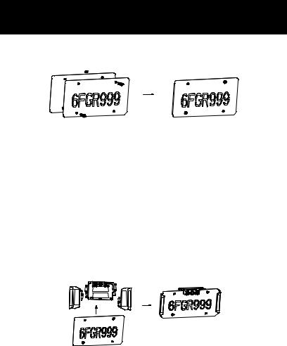
IMPORTANT: As license plate tolerances vary slightly in width and height, it is important that you follow the steps as outlined below:
1.Remove license plate from vehicle and place on top of the supplied license back plate.
2.Insert 2 short machine screws into 2 of the mounting holes and finger tighten 2 machine nuts onto them in order to hold the plates together for steps 3 thru 5.
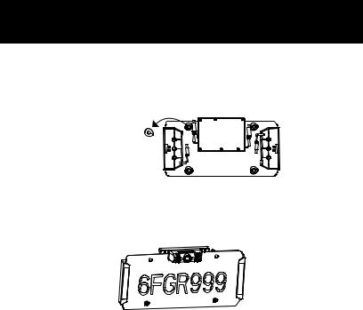
3.Peel the backing from the adhesive strips on the solar panel bases and carefully slide onto each side (left and right) of the plate assembly being careful not to make contact with the adhesive until the base is fully inserted.
4.With the solar mounts centrally positioned, apply pressure to set the adhesive tape.
5.Peel the backing from the adhesive strips on the camera base and carefully slide onto the long edge of the license plate assembly positioned centrally between the license plate mounting holes. Apply pressure to set the adhesive tape.
6
ASSEMBLY / INSTALLATION
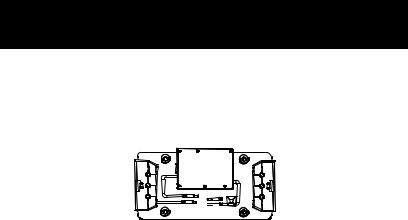
6.Remove the 2 short machine screws and nuts used earlier and set aside.
7.Peel the backing from the adhesive disks and apply one spacer over each license plate mounting hole.
Adhesive disks backing
8.Apply pressure to set the adhesive tape.
9.If two of the license plate mounting holes are not required for attachment to your vehicle, insert the short machine screws and tighten with the supplied machine nuts.
10.If needed, 2 cushions are provided to protect your vehicle. Attach to the back of the spacers containing the machine nuts.
7
ASSEMBLY / INSTALLATION
11.Connect the solar panel connectors to the mating connectors from the main camera housing and place the tie wrap adhesive pads as shown. Use 2 tie wraps to neatly hold the cables in place and cut the excess length of the tie wrap if desired. Follow illustration for correct wiring. Connect the A wires and connect the B wires.
A 
 B
B
B 

 A
A
12.Test the system in the "OPERATION" section of this guide before attaching the assembly to the vehicle with the appropriate license plate mounting screws for your vehicle type.
13.Ensure pairing between the backup camera and the monitor before mounting to your license plate.
NOTE: Domestic and Import license plate screws are included and should be compatible with the vast majority of vehicles. Should your vehicle require a special diameter or thread, please consult your dealer.
Tips to optimize the solar charge:
1.Be sure that the solar panels are clean, and dust/dirt-free.
2.Park in a location where the sun will shine directly on the solar panels for at least 1-2 hours a day.
3.One hour of good sunlight daily offsets the daily power consumption of the camera.
8

CAMERA ANGLE
The camera angle should be adjusted to provide an optimal view of objects behind the vehicle.
Note: Do not exceed 45 degrees up/down from central position.
Adjust the camera angle as required:
•Loosen the two screws below the camera a few turns.
•To adjust the camera angle, tilt the camera to the correct angle. (Do not force the camera)
•The camera should be adjusted to a horizontal position relative to the ground, so as to provide optimal view of objects behind the vehicle.
•Carefully tighten the 2 screws to prevent the camera angle from moving during vibrations from driving.
9
 Loading...