

Page 1
HIGH ALTITUDE / NATURAL GAS
TO PROPANE CONVERSION KIT
20491502 INSTALLATION INSTRUCTIONS
FOR ALTITUDES 4,500 - 7,000 FT. ONLY
Table of Contents
HIGH ALTITUDE KIT/PROPANE CONVERSION KIT SAFETY ................ 1
INSTALLATION REQUIREMENTS .............................................................2
Tools and Parts.........................................................................................2
Natural Gas Requirements .......................................................................2
LP Gas Requirements............................................................................... 3
INSTALLATION INSTRUCTIONS ...............................................................3
Convert Furnace - High Altitude Natural Gas Conversion....................... 3
Convert Furnace - High Altitude LP Gas Conversion .............................. 4
Make Gas Connections ............................................................................ 6
Check the Furnace Input Rate ................................................................. 7
Adjust the Furnace Input Rate.................................................................. 7
Complete Installation................................................................................ 7
HIGH ALTITUDE KIT/PROPANE CONVERSION KIT SAFETY
Your safety and the safety of others are very important.
We have provided many important safety messages in this manual and on your appliance. Always read and obey all
safety messages.
This is the safety alert symbol.
This symbol alerts you to potential hazards that can kill or hurt you and others.
All safety messages will follow the safety alert symbol and either the word “DANGER” or
“WARNING.” These words mean:
You can be killed or seriously injured if you don't
immediately follow instructions.
can be killed or seriously injured if you don't
You
follow instructions.
All safety messages will tell you what the potential hazard is, tell you how to reduce the chance of injury, and tell you
what can
This conversion kit shall be installed by a qualified service agency in accordance with the manufacturer’s instructions and
all applicable codes and requirements of the authority having jurisdiction. If the information in these instructions is not
followed exactly, a fire, explosion, or production of carbon monoxide may result, causing property damage, personal
injury, or loss of life. The qualified service agency is responsible for the proper installation of this kit. The installation is not
proper and complete until the operation of the converted appliance is checked as specified in the manufacturer’s
instructions supplied with the kit.
happen if the instructions are not followed.
WARNING
Model WPG
20563001
Page 2
Caution:
The gas supply shall be shut off prior to disconnecting the electrical power, before proceeding with the conversion.
ADDITIONAL SAFETY INFORMATION
In the State of Massachusetts, the following installation instructions apply:
■
Installations and repairs must be performed by a qualified or licensed contractor, plumber, or gasfitter qualified or
licensed by the State of Massachusetts.
■
If using a ball valve, it shall be a T-handle type.
■
A flexible gas connector, when used, must not exceed 3 feet.
INSTALLATION REQUIREMENTS
These instructions are intended as a general guide only and do
not supersede any national or local codes in any way. Compliance
with all local, state or national codes pertaining to this type of
equipment should be determined prior to installation.
Read this entire instruction manual as well as instructions
supplied with separate equipment before starting the installation.
This kit contains parts and instructions for converting natural gas
furnaces for use at altitudes from 4,500 to 7,000 ft. and also parts
and instructions for converting furnaces from natural gas to
propane at altitudes from 4,500 to 7,000 ft. In these instructions,
LP is an abbreviation for propane.
IMPORTANT:
■ For altitudes 7,000 to 10,000 ft above sea level, see Table F.4
in Appendix F of the National Fuel Gas Code (ANSI Z223.1/
NFPA 54, latest edition) for the correct orifice sizes.
■ The furnace is not recommended for installations above
10,000 ft.
■ It is recommended that the conversion be completed prior to
making final gas connections.
Tools and Parts
Check that you have everything necessary for correct installation.
Proper installation is your responsibility.
Assemble the required tools before starting installation. Read and
follow the instructions provided with any tools listed here.
Tools Needed:
■ Flat-blade and Phillips
screwdrivers
■ ³⁄₁₆ in. Allen wrench
■ ⁵⁄₁₆ in. nut driver
■ ¹⁄₄ in. nut driver
■ ⁷⁄₁₆ in. open-end wrench
■ Pipe wrench
■ Adjustable wrench
■ Thread sealant
■ Noncorrosive leak
detection solution
■ Test g aug e wi th ¹⁄₈ in. NPT
connection (for measuring
gas supply pressure)
Parts Supplied:
High Altitude Conversion for Natural Gas:
■ Pressure switch
High Altitude Conversion for Propane:
■ Pressure switch
■ #8 x 1 in. spoiler
screws (5)
■ Conversion plate label
■ #55 size orifice (5)
■ Gas conversion manifold
label
■ Conversion kit for gas
control valve
Parts Needed:
■ For high altitude conversion for natural gas, read “LP Gas
Requirements” and check local codes and ordinances before
purchasing parts.
■ For high altitude conversion to propane, read “Natural Gas
Requirements” before purchasing parts.
Natural Gas Requirements
■ The minimum Natural Gas pressure required at the furnace is
4.5 in. W.C.
■ The maximum Natural Gas pressure allowed at the furnace is
10 in. W.C.
■ An orifice change is required. See “Natural Gas Orifice
Requirements” chart.
Natural Gas Orifice Requirements
Altitude (ft) 4,500-6,000 6,000-7,000
Orifice size 44 45
2
Page 3
LP Gas Requirements
2
4
5
6
3
The furnace has a regulator in the gas control valve. A regulator is
also required on the propane tank. Another regulator is required at
the house or unit.
■ The minimum LP Gas pressure required at the furnace
is 11 in. W.C.
■ The maximum LP Gas pressure allowed at the furnace
is 13 in. W.C.
■ An orifice change is required. Use the #55 orifices provided in
the kit for propane conversion.
INSTALLATION
INSTRUCTIONS
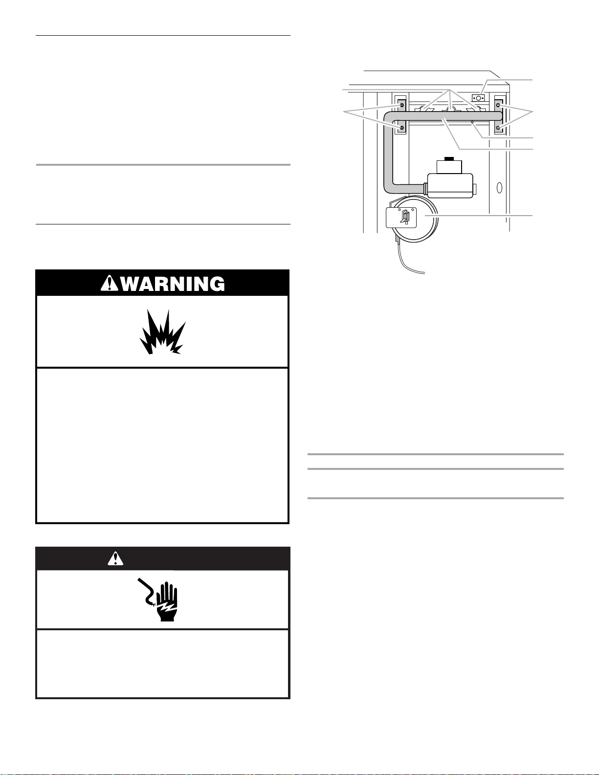
Convert Furnace - High Altitude
Natural Gas Conversion
3. Remove the burner access door.
4. Remove the pressure tube and wires from the pressure
switch.
1
3
Explosion Hazard
Furnace must be installed and serviced by a
qualified person.
Examples of a qualified person include:
licensed heating personnel,
authorized gas company personnel.
Read and follow all instructions provided for
installation, adjustment, service, alteration, or
maintenance.
Failure to follow these instructions can result in death,
explosion, fire, or carbon monoxide poisoning.
WARNING
1. Orifice locations
2. Rollout switch location
3. Mounting screws
5. Replace the pressure switch with the pressure switch
provided in the kit.
6. Connect the pressure tube and wires to the new pressure
switch.
7. Disconnect all wires from gas control valve.
8. Disconnect the rollout switch and flame sensor wires.
9. Remove the manifold pipe from the burner assembly by
removing the 4 mounting screws.
10. Slide the manifold pipe (with gas control valve) forward and
out of the control compartment.
11. Remove the orifices from the manifold. Thread in the new
Natural Gas orifices of the correct size. See “Natural Gas
Orifice Requirements” chart.
Natural Gas Orifice Requirements
Altitude (ft) 4,500-6,000 6,000-7,000
Orifice size 44 45
NOTE: Make sure that the orifices are straight and positioned
at a 90º angle to the manifold.
12. Reinstall the manifold pipe to the burner assembly.
13. Reconnect all wires on the gas control valve.
14. Reconnect rollout switch and flame sensor wires.
15. Replace the burner access door.
16. Dispose of all remaining parts.
17. Go to “Make Gas Connections.”
4. Flame sensor location
5. Manifold
6. Pressure switch
Electrical Shock Hazard
Disconnect power before servicing.
Replace all parts and panels before operating.
Failure to do so can result in death or electrical shock.
1. Turn off gas supply at manual gas shutoff valve.
2. Disconnect power.
3
Page 4

Convert Furnace - High Altitude
2
4
5
6
3
5
4
LP Gas Conversion
Explosion Hazard
Furnace must be installed and serviced by a
qualified person.
Examples of a qualified person include:
licensed heating personnel,
authorized gas company personnel.
Read and follow all instructions provided for
installation, adjustment, service, alteration, or
maintenance.
Failure to follow these instructions can result in death,
explosion, fire, or carbon monoxide poisoning.
WARNING
6. Remove the manifold pipe from the burner assembly by
removing the 4 mounting screws.
1
3
1. Orifice locations
2. Rollout switch location
3. Mounting screws
4. Flame sensor location
5. Manifold
6. Pressure switch
7. Slide the manifold pipe (with gas control valve) forward and
out of the control compartment.
8. Remove the regulator adjustment cap with “O” ring, pressure
regulator adjusting screw, and spring from the gas control
valve. See “Gas Control Valve.”
Gas Control Valve
OFF
Electrical Shock Hazard
Disconnect power before servicing.
Replace all parts and panels before operating.
Failure to do so can result in death or electrical shock.
1. Turn off gas supply at manual gas shutoff valve.
2. Disconnect power.
3. Remove the burner access door.
4. Disconnect all wires from gas control valve.
5. Disconnect the rollout switch and flame sensor wires.
1
2
3
1. Gas control knob
2. Gas outlet
3. Outlet pressure tap
4. Gas inlet
5. Inlet pressure tap
ON
6. Regulator adjustment cap
7. “O” ring
8. Pressure regulator adjusting screw
9. Spring
IN
PSI
6
6
7
8
9
4
Page 5

9. Convert the Gas Control Valve for LP Gas.
4
3
4
2
4
5
6
3
■ Open the plastic bag included in this kit.
■ Locate the new spring (different color) and install.
■ Locate the new pressure regulator adjusting screw and
thread in such a way that the top of the regulator adjusting
screw is flush with the surface of the gas control valve.
■ Turn regulator adjusting screw clockwise 11 full turns.
■ Install new “O” ring into new regulator adjustment cap
(BLACK).
■ Install the new regulator adjustment cap (BLACK).
■ Affix the gas control valve conversion label included in the
plastic bag to the top of the gas control valve.
10. Remove the orifices from the manifold. Thread in the new
#55 LP Gas orifices located in the kit.
NOTE: Make sure that the orifices are straight and positioned
at a 90º angle to the manifold.
11. Remove the #10 screws that secure the burner assembly to
the flue panel.
12. Remove burner assembly from vestibule compartment. Be
careful to support burner opening inlet plate.
Manifold and Burner Assembly
13. Remove two (2) screws securing top air shield to burner
assembly. Move top air shield to allow access to spoiler
screws holes. See “Manifold and Burner Assembly.”
14. Install spoiler screws into each burner. Thread screw down
until the head of the screw just touches the surface of the
burner. Make sure not to overtighten. See “Orifice and Spoiler
Screw Location.”
15. Reinstall the top air shield.
16. Reinstall burner assembly with burner opening inlet plate.
Burner opening inlet plate must rest against flue panel.
17. Reinstall the manifold pipe to the burner assembly.
IMPORTANT: Ensure that the burner igniter is aligned properly
with the burner. The burner igniter tube should be aligned
vertically as shown.
1
2
1
2
1
2
3
1. Top shield
2. Burner opening inlet plate
3. Manifold
Orifice and Spoiler Screw Location
1
2
4. Spoiler screw
5. Burner
1. Burner igniter tube
2. Burner throat
18. Affix the gas conversion manifold label “This control has been
converted for use with propane gas” to the manifold in a
visible location.
19. Reconnect all wires on the gas control valve.
20. Reconnect rollout switch and flame sensor wires.
5
1
3
1. Manifold
2. Orifice
3. Spoiler screw
4. Burner
1. Orifice locations
2. Rollout switch location
3. Mounting screws
4. Flame sensor location
5. Manifold
6. Pressure switch
21. Fill in the required information on the conversion plate label
(day-month-year of conversion, and the name and address of
the organization making this conversion).
22. Attach conversion plate label to the exterior panel adjacent to
the unit rating plate.
23. Replace the burner access door.
24. Dispose of all remaining parts.
25. Go to “Make Gas Connections.”
5
Page 6

Make Gas Connections
4
5
5
2
WARNING
FIRE OR EXPLOSION HAZARD
Failure to follow the safety warnings exactly could result
in serious injury, death or property damage.
Never test for gas leaks with an open flame. Use a
commercially available soap solution made specifically
for the detection of leaks to check all connections. A fire
or explosion may result causing property damage,
personal injury or loss of life.
1. Install the field gas supply for either side or bottom gas pipe
entry as shown.
2. Provide a sediment trap on the outside of the furnace section
in accordance with any local codes.
3. Install a manual gas shutoff valve in the gas line, outside the
unit in accordance with any local codes.
4. Install a test gauge connection with a ¹⁄₈ in. NPT plugged
tapping immediately upstream of the manual gas shutoff valve
as shown.
5. Connect the gas pipe to the furnace controls providing a
ground joint union as close to the controls as possible to
facilitate removal of controls and manifold.
Pipe-joint compounds suitable for use with natural and LP gas
must be used. Do not use Teflon
®
tape.
1
2
3
4
1. Ground joint union
2. Gas control valve
3. Control drawer
4. Bottom entry
¹⁄₈
in. NPT plugged tapping
5.
6. Manual gas shutoff valve
7. Sediment trap
Check Inlet Pressure
1. Turn off the gas supply at the manual gas shutoff valve.
1
6
7
Side Gas Pipe Entry
Side entry is the primary method of routing the gas supply to
the unit. Use the factory provided grommet to seal the
opening around the gas pipe preventing rain and moisture
from entering the unit.
1
2
6" Min.
3
1. Manual gas shutoff valve
¹⁄₈
in. NPT plugged tapping
2.
3. Sediment trap
4. Ground joint union
5. Grommet
Bottom Gas Pipe Entry
When bottom entry of gas pipe is used, the side entry hole must
first be completely covered by a field-provided plug. Route the
pipe up through the bottom entry hole and immediately into an
elbow to route pipe along the base of the unit. Use another elbow
to route gas pipe up through holes provided in control drawer
mount. One more elbow will route the pipe to the union and gas
control valve.
1. Closed valve
2. Open valve
2. Remove the inlet pressure tap plug on the gas control valve.
3. Install a ¹⁄₈ in. NPT hose connector and connect the pressure
gauge tube.
Gas Control Valve
OFF
1
NPT Outlet
2
1. Gas control knob
¹⁄₈
in. NPT outlet pressure tap
2.
4. Turn on the gas supply at the manual gas shutoff valve.
5. Turn on the electrical power to the furnace.
6. To light the main burners, set the room thermostat to a point
above room temperature.
NOTE: This furnace is equipped with an ignition device, which
automatically lights the burner. This furnace cannot be lighted
manually. Do not try to light the burner by hand.
ON
¹⁄₈
in. NPT inlet pressure tap
3.
4. Regulator adjustment cap
NPT Inlet
IN
PSI
3
4
®Teflon is a registered trademark of E.I. Dupont de Nemours and Company.
6
Page 7

7. Check minimum inlet gas supply pressure.
■ Turn on all other gas appliances.
■ Observe the pressure rating on the pressure gauge. The
minimum inlet gas supply pressure is 4.5 in. W.C. for
natural gas and 11 in. W.C. for propane gas.
8. Check maximum inlet gas supply pressure.
■ Turn off all other gas appliances.
■ Observe the pressure reading on the pressure gauge. The
maximum inlet gas supply pressure is 10 in. W.C. for
natural gas and 13 in. W.C. for propane gas.
IMPORTANT: If the inlet gas supply pressure is not within the
minimum and maximum range as shown on the rating plate,
contact your gas supplier.
9. Turn off the electrical power to the furnace.
10. Turn off the gas supply at the manual gas shutoff valve.
11. Remove the pressure gauge tube and the ¹⁄₈ in. hose
connector.
12. Replace the inlet pressure tap plug on the gas control valve.
13. Turn on the gas supply at the manual gas shutoff valve.
14. Test all connections by brushing on an approved noncorrosive
leak-detection solution. Bubbles will show a leak. Correct any
leak found.
■ At test pressures greater than ¹⁄₂ psig (3.5 kPa), the
furnace and the manual gas shutoff valve must be
disconnected from the gas supply piping system.
■ At test pressures less than or equal to ¹⁄₂ psig (3.5 kPa), the
furnace must be isolated from the gas supply piping
system by closing the manual gas shutoff valve.
Check the Furnace Input Rate
(if required)
BTU ratings shown on the furnace rating plate are for elevations
up to 2,000 ft.
IMPORTANT:
■ The furnace input rate must not exceed the input rating on the
furnace rating plate.
■ For elevations above 2,000 ft, the ratings should be reduced
at the rate of 4% for each 1,000 ft above sea level.
■ This furnace is equipped for rated input at manifold pressure
of 3.5 in. W.C. for natural gas.
■ This furnace is equipped for rated input at manifold pressure
of 10.0 in. W.C. for propane gas.
■ The actual heating value of your propane gas can be obtained
from your local gas supplier.
5. Move the gas control knob to the ON position.
NOTE: This furnace is equipped with an ignition device which
automatically lights the burner. This furnace cannot be lighted
manually. Do not try to light the burner by hand.
6. Turn on the electrical power to the furnace.
7. To light the main burners, set the room thermostat to a point
above room temperature .
8. Observe the pressure reading on the pressure gauge. If
necessary, adjust the manifold pressure to 3.5 in. W.C. for
natural gas and 10.0 in. W.C. for propane gas.
9. If necessary, remove the regulator adjusting cap on the gas
control valve and turn the regulator adjusting screw clockwise
to increase pressure and input, or counterclockwise to
decrease pressure and input.
IMPORTANT: If the manifold pressure cannot be adjusted to
the correct value, contact your gas supplier.
10. Move the gas control knob to the OFF position.
11. Disconnect the pressure gauge from the ¹⁄₈ in. NPT outlet
pressure tap.
12. Replace outlet pressure tap plug and the regulator adjusting
cap on the gas valve.
13. Move the gas control knob to the ON position.
14. Replace the burner access door.
15. Set the room thermostat to the desired temperature necessary
to achieve optimum temperature rise.
Complete Installation
IMPORTANT: Do not use this furnace if any part has been under
water. Immediately call a qualified person to inspect the furnace
and to replace any part of the control system and gas control
which has been under water.
1. Check to be sure you have all of your tools.
2. Dispose of all packaging materials.
3. Check the furnace in its final location. Be sure the vent is not
blocked.
Measure Temperature Rise
1. After 20 minutes of heating operation, measure the furnace
temperature rise. Take air temperature readings in both the
return air ducts and the heated air ducts.
2. If furnace doesn’t maintain temperature rise within the range
shown on the furnace rating plate, adjust the blower speed.
Adjust Blower Speed
Adjust the Furnace Input Rate
For installations above 2,000 ft, the furnace input rate is to be
reduced per the requirements of the National Fuel Gas Code
(ANSI Z223.1/NFPA 54, latest edition), at the rate of 4% for each
1,000 ft above sea level.
1. Remove the burner access door.
2. Move the gas control knob to the OFF position. Use only your
hand to move the gas control knob; tools are not required.
3. Remove the outlet pressure tap plug on the gas valve and
connect pressure gauge to the ¹⁄₈ in. NPT outlet pressure tap.
4. Be sure the gas control knob has been in the OFF position for
at least 5 minutes before starting the unit.
WARNING
Electrical Shock Hazard
Disconnect power before servicing.
Replace all parts and panels before operating.
Failure to do so can result in death or electrical shock.
NOTE: See the “Wiring Connection Diagram” while performing
the following procedure.
7
Page 8

Blower Speed Tap Change
1
Red
Blue
White
Red
Blue
LOW
MED
HIGH
COM
UNUSED
HEAT
COOL
Violet
To Select Different Speeds for COOL and HEAT
At the Blower Motor Connector
1. Disconnect power.
2. Remove blower access panel.
3. Place blue wire on the HIGH, MED or LOW motor speed tap,
as desired for COOLING.
4. Place red wire on any of the other motor speed taps for
HEATING.
At the Unit Control Board
1. Remove and discard the violet jumper wire from the COOL
terminal to the HEAT terminal.
2
3
2. Place blue wire on the COOL terminal.
3. Place red wire on the HEAT terminal.
4. Replace blower access panel.
5. Reconnect power.
Factory Setting Heat/Cool Speeds
Unit Heat Cool
1. Blower motor connector
2. Control board
3. Jumper wire
Select the Same Speed for COOL and HEAT
At the Blower Motor Connector
1. Disconnect power.
2. Remove blower access panel.
3. Place blue wire on the HIGH, MED or LOW motor speed tap,
as desired.
4. Place red wire on any of the other motor speed taps.
5. Reconnect power.
At the Furnace Control Board
1. Place red wire on the UNUSED terminal.
2. Place blue wire (with piggyback terminal) on the COOL
terminal.
3. Place the factory supplied violet jumper wire from the COOL
terminal to the HEAT terminal.
WPG124, 130, 136, 148, 230, 236 MED MED
WPG248A125 MED MED
WPG142, 160, 242 MED HIGH
WPG260A125 MED HIGH
WPG224 LOW MED
WPG248A100 MED LOW
Shut Down the Furnace
1. Set the room thermostat to the lowest setting.
2. Disconnect power.
3. Remove burner access door.
4. Shut off the gas by moving the gas control knob to the OFF
position.
5. Replace the burner access door.
See your Furnace Installation Instructions for troubleshooting
information.
20563001
© 2003. All rights reserved.
Printed in U.S.A.
10/03
 Loading...