


MICROWAVE HOOD COMBINATION
INSTALLATION INSTRUCTIONS
This product is suitable for use above electric or gas cooking products up to and including 36" (91.4 cm) wide. See the “Installation Requirements” section for further notes.
These installation instructions cover different models. The appearance of your particular model may differ slightly from the illustration in these installation instructions.
Table of Contents |
|
MICROWAVE HOOD COMBINATION SAFETY |
............................1 |
INSTALLATION REQUIREMENTS................................................. |
2 |
Tools and Parts............................................................................. |
2 |
Location Requirements................................................................. |
2 |
Product Dimensions..................................................................... |
3 |
Electrical Requirements................................................................ |
3 |
INSTALLATION INSTRUCTIONS................................................... |
4 |
Remove Mounting Plate............................................................... |
4 |
Rotate Blower Motor.................................................................... |
4 |
Locate Wall Stud(s)....................................................................... |
6 |
Mark Rear Wall.............................................................................. |
7 |
Drill Holes in Rear Wall.................................................................. |
7 |
Attach Mounting Plate to Wall...................................................... |
8 |
Prepare Upper Cabinet................................................................. |
8 |
Install Damper Assembly.............................................................. |
9 |
Install the Microwave Oven.......................................................... |
9 |
Complete Installation.................................................................. |
10 |
VENTING DESIGN SPECIFICATIONS......................................... |
11 |
ASSISTANCE................................................................................. |
12 |
Replacement Parts..................................................................... |
12 |
Accessories................................................................................. |
12 |
MICROWAVE HOOD COMBINATION SAFETY
W11087690A
INSTALLATION REQUIREMENTS
Tools and Parts
Tools Needed:
Gather the required tools and parts before starting installation. Read and follow the instructions provided with any tools listed here.
■■ Measuring tape ■■ Pencil
■■ Masking tape or thumbtacks
■■ Scissors
■■ No. 2 Phillips screwdriver
■■ No. 3 Phillips screwdriver for 1/4-20 x 3" (7.6 cm) bolts
■■ Drill
■■ 3/16" (5 mm), 3/8" (10 mm), 5/8" (16 mm) drill bits
■■ 3/4" (19 mm) hole saw
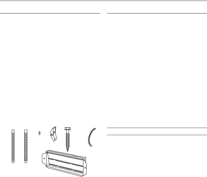
Parts Supplied:
■■ Diagonal wire cutting pliers ■■ Stud finder
■■ 7/16" (1.1 cm) socket wrench (or box wrench) for 1/4" x 2" (0.64 cm x 5.1 cm) lag screws
■■ 11/2" (3.8 cm) diam. hole drill bit for wood or metal cabinet
■■ Keyhole saw
■■ Caulking gun and weatherproof caulking compound
■■ Duct tape
For information on reordering, see the “Replacement Parts” section.
NOTE: The hardware items listed here are for wood studs. For other types of wall structures, be sure to use appropriate fasteners.
A  B
B C
C  D
D  E
E F
F  G
G
H
A.3/16-24 x 3" (7.6 cm) roundhead bolts (2)
B.1/4-20 x 3" (7.6 cm) flat-head bolts (2)
C.Washers (2)
D.3/16" (4.8 mm) toggle nuts (2)
E.1/4" x 2" (0.64 cm x 5.1 cm) lag screws (2)
F.Sheet metal screws (2)
G.Power supply cord bushing (1)
H.Damper assembly (for wall or roof venting)
Not Shown:
Upper cabinet template
Mounting plate (attached to back of microwave oven)
Wall template Aluminum grease filters
Charcoal filters (Depending on model, charcoal filters may not be included.
See User Instructions.)
NOTE: Depending on model, aluminum grease filter and charcoal filter may be combined.
Materials needed:
■■ Standard fittings for wall or roof venting. See the “Venting Design Specifications” section.
Location Requirements
Check the opening where the microwave oven will be installed. The location must provide:
■■ Minimum installation dimensions. See “Installation Dimensions” illustration.
■■ Minimum one 2" x 4" (50.8 mm x 101.6 mm) wood wall stud and minimum 3/8" (10 mm) thickness drywall or plaster/lath within cabinet opening.
■■ Support for weight of 150 lbs (68 kg), which includes microwave oven and items placed inside the microwave oven and upper cabinet.
■■ Grounded electrical outlet inside upper cabinet. See the “Electrical Requirements” section.
NOTES:
■■ If installing the microwave oven near a left sidewall, make sure there is at least 6" (15.2 cm) of clearance between the wall and the microwave oven, so that the door can open fully.
■■ If installing the microwave oven near a right sidewall, make sure there is at least 3" (7.6 cm) of clearance between the wall and the microwave oven, so that you can grab the handle integrated inside the door.
■■ Some cabinet and building materials are not designed to withstand the heat produced by the microwave oven for cooking. Check with your builder or cabinet supplier to make sure that the materials used will not discolor, delaminate, or sustain other damages.
Special Requirements
For Wall Venting Installation Only:
■■ Cutout must be free of any obstructions so that the vent fits properly and the damper blade opens freely and fully.
For Roof Venting Installation Only:
■■ If you are using a rectangular to round transition piece, the 3" (7.6 cm) clearance needs to exist above the microwave oven so that the damper blade can open freely and fully. See “Rectangular to Round Transition” illustration in the “Venting Design Specifications” section.
2
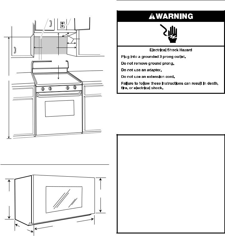
Installation Dimensions:
NOTE: The grounded 3 prong outlet must be inside the upper cabinet. See the “Electrical Requirements” section.
A B
Electrical Requirements
30" (76.2 cm) min.
30" (76.2 cm) typical*
66" (167.6 cm) min.
12" (30.5 cm) min. 14" (35.6 cm) max.
upper cabinet and side cabinet depth
A.2" x 4" (50.8 mm x 101.6 mm) wall stud
B.Grounded 3 prong outlet
*30" (76.2 cm) is typical for 66" (167.6 cm) installation height. Exact dimensions may vary depending on type of range/cooktop below.
Product Dimensions
17¹⁄"
(43.5 cm) +/- ³⁄" (0.5 cm)
|
Up |
to |
|||
16 |
|
||||
(42. |
|
|
|
" |
|
5 |
|
³⁄ |
|||
cm)* |
|||||
|
|
||||
16¹⁄" (41.3 cm)
|
|
.0cm) |
|
"(76 |
|
⁄ |
|
|
29 |
|
|
*Overall depth of product will vary slightly depending on door design.
Observe all governing codes and ordinances.
Required:
■■ A 120-volt, 60 Hz, AC-only, 15or 20-amp electrical supply with a fuse or circuit breaker.
Recommended:
■■ A time-delay fuse or time-delay circuit breaker.
■■ A separate circuit serving only this microwave oven.
GROUNDING INSTRUCTIONS
■For all cord connected appliances:
The microwave oven must be grounded. In the event of an electrical short circuit, grounding reduces the risk of electric shock by providing an escape wire for the electric current. The microwave oven is equipped with a cord having a grounding wire with a grounding plug. The plug must be plugged into an outlet that is properly installed and grounded.
WARNING: Improper use of the grounding plug can result in a risk of electric shock. Consult a qualified electrician or serviceman if the grounding instructions are not completely understood, or if doubt exists as to whether the microwave oven is properly grounded.
Do not use an extension cord. If the power supply cord is too short, have a qualified electrician or serviceman install an outlet near the microwave oven.
SAVETHESE INSTRUCTIONS
3
INSTALLATION INSTRUCTIONS
Remove Mounting Plate
Depending on your model, the mounting plate may be in the foam packaging or it may be attached
to the back of the microwave oven.
NOTE: To avoid possible damage to the work surface, cover the work surface.
1.Remove any remaining contents from the microwave oven cavity.
2.If the mounting plate is attached to the back of the microwave oven, remove it and set it aside.
3.Tape the microwave oven door closed so that door does not swing open while the microwave oven is being handled.
NOTE: To avoid damage to the microwave oven, do not grip or use the door or door handle while the microwave oven
is being handled.
Rotate Blower Motor
The microwave oven is set for recirculation installation. For wall or roof venting, changes must be made to the venting system.
NOTE: Skip this section if you are using recirculation installation. Keep the damper assembly in case the venting method
is changed or the microwave oven is reinstalled in another location where wall or roof venting may be used.
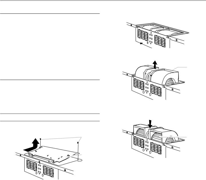
Wall Venting Installation Only
1.Remove screws attaching damper plate to top of microwave oven exterior. Slide damper plate toward the front of the microwave oven and lift up.
A
 B
B
A.Screws
B.Damper plate
2.Keep damper plate and screws together and set aside.
3.Remove 2 screws attaching blower motor to back of microwave oven.
A


A.Screws (in recessed holes)
4.Lift blower motor out of microwave oven.
A
A.Blower motor
5.Rotate blower motor 180° so that exhaust ports face the back of microwave oven, and lower blower motor back into the microwave oven.
A
A. Exhaust port
4
 Loading...