

Whirlpool WHESCS Installation And Operation Manual
Model WHESCS
How to install, operate
and maintain your Demand
Controlled Water Softener
Do not return water softener to store
If you have any questions or concerns when
installing, operating or maintaining your water
softener, call our toll free number:
1-866-986-3223
Monday- Friday, 8 AM - 7 PM EST or visit
www.whirlpoolwatersofteners.com
When you call, please be prepared to provide
the model and serial number of your product,
found on the rating decal, typically located on
the rim below the salt lid hinges.
System tested and certified by NSF International
against NSF/ANSI Standard 44
for hardness reduction and efficiency,
and certified to NSF/ANSI Standard 372.
System tested and certified by the Water Quality
Association against CSA B483.1.
Manufactured and warranted by
Ecodyne Water Systems
1890 Woodlane Drive
Woodbury, MN 55125
Installation and Operation Manual
7349641 (Rev. C 3/20/17)

TABLE OF CONTENTS
Page
pecifications & Performance Claims . . . . . . . . . . . . . . . . . . . . . . . . . . . . . . . . . . . . . . . . . . . . . . . . . . . . . . . . . . . . 3
S
Water Softener Safety . . . . . . . . . . . . . . . . . . . . . . . . . . . . . . . . . . . . . . . . . . . . . . . . . . . . . . . . . . . . . . . . . . . . . . . . 4
Before You Start . . . . . . . . . . . . . . . . . . . . . . . . . . . . . . . . . . . . . . . . . . . . . . . . . . . . . . . . . . . . . . . . . . . . . . . . . . . . 4
Inspect Shipment . . . . . . . . . . . . . . . . . . . . . . . . . . . . . . . . . . . . . . . . . . . . . . . . . . . . . . . . . . . . . . . . . . . . . . . . . . . . 5
ater Conditioning Information . . . . . . . . . . . . . . . . . . . . . . . . . . . . . . . . . . . . . . . . . . . . . . . . . . . . . . . . . . . . . . . . . 5
W
Installation Requirements . . . . . . . . . . . . . . . . . . . . . . . . . . . . . . . . . . . . . . . . . . . . . . . . . . . . . . . . . . . . . . . . . . . . 6-7
imensions . . . . . . . . . . . . . . . . . . . . . . . . . . . . . . . . . . . . . . . . . . . . . . . . . . . . . . . . . . . . . . . . . . . . . . . . . . . . . . . . 8
D
Installation Instructions . . . . . . . . . . . . . . . . . . . . . . . . . . . . . . . . . . . . . . . . . . . . . . . . . . . . . . . . . . . . . . . . . . . . . 8-11
Programming the Water Softener . . . . . . . . . . . . . . . . . . . . . . . . . . . . . . . . . . . . . . . . . . . . . . . . . . . . . . . . . . . 12-14
Connecting to the Iris™ Cloud . . . . . . . . . . . . . . . . . . . . . . . . . . . . . . . . . . . . . . . . . . . . . . . . . . . . . . . . . . . . . . . . 15
Customizing Features / Options . . . . . . . . . . . . . . . . . . . . . . . . . . . . . . . . . . . . . . . . . . . . . . . . . . . . . . . . . . . . . 16-18
Routine Maintenance . . . . . . . . . . . . . . . . . . . . . . . . . . . . . . . . . . . . . . . . . . . . . . . . . . . . . . . . . . . . . . . . . . . . . 18-19
Troubleshooting . . . . . . . . . . . . . . . . . . . . . . . . . . . . . . . . . . . . . . . . . . . . . . . . . . . . . . . . . . . . . . . . . . . . . . . . . 20-21
Exploded View & Parts List . . . . . . . . . . . . . . . . . . . . . . . . . . . . . . . . . . . . . . . . . . . . . . . . . . . . . . . . . . . . . . . . 22-25
Warranty . . . . . . . . . . . . . . . . . . . . . . . . . . . . . . . . . . . . . . . . . . . . . . . . . . . . . . . . . . . . . . . . . . . . . . . . . . . . . . . . . 26
FCC NOTICE
NOTE: This equipment has been tested and found to
comply with the limits for a Class B digital device, pursuant to Part 15 of the FCC Rules. These limits are
designed to provide reasonable protection against
harmful interference in a residential installation. This
equipment generates, uses, and can radiate radio frequency energy and, if not installed and used in accordance with the instructions may cause harmful interference to radio communications.
However, there is no guarantee that interference will
not occur in a particular installation. If this equipment
does cause harmful interference to radio or television
reception, which can be determined by turning the
equipment off and on, the user is encouraged to try to
correct the interference by one or more of the following
measures:
= Reorient or relocate the receiving antenna.
= Increase the separation between the equipment
and receiver.
= Connect the equipment into an outlet on a circuit
different from that to which the receiver is connected.
= Consult the dealer or an experienced radio/TV
technician for help.
INDUSTRY CANADA NOTICE
This device complies with Industry Canada Standard
RSS-210. Operation is subject to the following two
conditions: (1) this device may not cause interference,
and (2) this device must accept any interference,
including interference that may cause undesired operation of the device.
IMPORTANT: Changes or modifications not expressly
approved by the party responsible for compliance
could void the user’s authority to operate the equipment.
2
Specifications & Performance Claims
This model is efficiency rated. The efficiency rating is valid only at the minimum salt dose. The softener has a
demand initiated regeneration (D.I.R.) feature that complies with specific performance specifications intended to minimize the amount of regenerant brine and water used in its operation.
This softener has a rated softener efficiency of not less than 3,350 grains of total hardness exchange per pound of
alt (based on sodium chloride) and shall not deliver more salt than its listed rating or be operated at a sustained
s
maximum service flow rate greater than its listed rating. This softener has been proven to deliver soft water for at
least ten continuous minutes at the rated service flow rate. The rated salt efficiency is measured by laboratory tests
described in NSF/ANSI Standard 44. These tests represent the maximum possible efficiency that the system can
achieve. Operational efficiency is the actual efficiency after the system has been installed. It is typically less than
the rated efficiency, due to individual application factors including water hardness, water usage, and other contaminants that reduce a softener's capacity.
Model WHESCS
Model Code LLCS
18,000 @ 3.8 lbs.
Rated Softening Capacity (Grains @ Salt Dose)
Rated Efficiency (Grains/Pound of Salt @ Minimum Salt Dose) 4,711 @ 3.8 lbs.
Water Used During Regeneration @ Minimum Salt Dose 3.0 gal. / 1,000 grains
Total Water Used Per Regeneration @ Maximum Salt Dose 50 gallons
Rated Service Flow Rate 10 gpm
Amount of High Capacity Ion Exchange Resin 1.27 cu. ft.
Pressure Drop at Rated Service Flow 12.5 psig
Water Supply Max. Hardness 150 gpg
Water Supply Max. Clear Water Iron 12 ppm*
Water Pressure Limits (minimum / maximum) 20 - 125 psi**
Water Temperature Limits (minimum / maximum) 40 - 120 °F
Minimum Water Supply Flow Rate 3 gpm
Intermittent Flow @ 30 PSI 17.5 gpm***
Maximum Drain Flow Rate 2.0 gpm
Salt Storage Capacity 200 lbs.
36,400 @ 10.1 lbs.
46,000 @ 17.4 lbs.
*Capacity to reduce clear water iron is substantiated by WQA test data. State of Wisconsin
requires additional treatment if water supply contains clear water iron exceeding 5 ppm.
**Canada working pressure limits: 1.4 - 7.0 kg/cm
***Intermittent flow rate does not represent the maximum service flow rate used for deter-
mining the softener’s rated capacity and efficiency. Continuous operation at flow rates
greater than the service flow rate may affect capacity and efficiency performance.
This system conforms to NSF/ANSI 44 for the specific performance claims as verified and
substantiated by test data.
Variable Salt Dose: The salt dose is selected by the electronic controls at regeneration
time based on the amount needed.
Questions? Call Toll Free 1-866-986-3223 Monday- Friday, 8 AM - 7 PM EST
or visit www.whirlpoolwatersofteners.com
When you call, please be prepared to provide the model and serial number,
found on the rating decal, typically located on the rim below the salt lid hinges.
2
.
3
Water Softener Safety
Your safety and the safety of others are very important.
We have provided many safety messages in this manual and on your appliance. Always read and obey all safety
essages.
m
This is the safety alert symbol.
This symbol alerts you to potential hazards that can kill or hurt you and others.
All safety messages will follow the safety alert symbol and either the word “DANGER” or “WARNING”
These words mean:
You can be killed or seriously injured if you don’t
immediately
You can be killed or seriously injured if you don’t
follow instructions.
All safety messages will tell you what the potential hazard is, tell you how to reduce the chance of injury, and tell
you what can happen if the instructions are not followed.
In the state of Massachusetts: The Commonwealth of Massachusetts plumbing code 248-CMR shall
be adhered to. A licensed plumber shall be used for this installation.
follow instructions.
In the state of California: You must turn the Salt Efficiency Feature setting to ON. This may initiate
more frequent recharges. However, it will operate at 4,000 grains per pound of salt or higher. To turn
on the Salt Efficiency Feature, follow the instructions in the “Salt Efficiency” section of this manual.
Before You Start
= The water softener requires a minimum water flow of 3 gallons per minute at the inlet. Maximum allowable inlet
water pressure is 125 psi. If daytime pressure is over 80 psi, nighttime pressure may exceed the maximum. Use
a pressure reducing valve if necessary (Adding a pressure reducing valve may reduce the flow). If your home is
equipped with a back flow preventer, an expansion tank must be installed in accordance with local codes and
laws.
= The water softener works on 24V DC electrical power, supplied by a direct plug-in power supply (included). Be
sure to use the included power supply and plug it into a nominal 120V, 60 Hz household outlet that is in a dry
location only, grounded and properly protected by an overcurrent device such as a circuit breaker or fuse.
= Do not use this system to treat water that is microbiologically unsafe or of unknown quality without adequate dis-
infection upstream or downstream of the system.
European Directive 2002/96/EC requires all electrical and electronic equipment to be disposed of accord-
ing to Waste Electrical and Electronic Equipment (WEEE) requirements. This directive or similar laws are
in place nationally and can vary from region to region. Please refer to your state and local laws for proper
disposal of this equipment.
Do not return the water softener to store.
If you have any questions, or there are missing parts or damage, please call Toll Free 1-866-986-3223,
Monday - Friday, 8 am - 7 pm EST, or visit www.whirlpoolwatersofteners.com
When you call, please be prepared to provide the model and serial number, found on the rating decal,
typically located on the rim below the salt lid hinges.
4
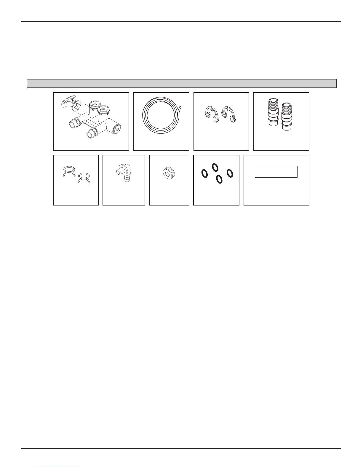
Inspect Shipment
The parts required to assemble and install the water
softener are included with the unit. Thoroughly check
the water softener for possible shipping damage and
arts loss. Also inspect and note any damage to the
p
shipping carton.
Packing List
Drain HoseBypass Valve Clips
Adaptor
Hose Clamps
Elbow
Grommet O-rings
Remove and discard (or recycle) all packing materials.
To avoid loss of small parts, we suggest you keep the
small parts in the parts bag until you are ready to use
hem.
t
Installation
Adaptors
Water Hardness
Test Strip
FIG. 1
Water Conditioning Information
IRON
Iron in water can cause stains on clothing and plumbing fixtures. It can negatively affect the taste of food,
drinking water, and other beverages. Iron in water is
measured in parts per million (ppm). The total* ppm of
iron, and type or types*, is determined by chemical
analysis. Four different types of iron in water are:
= Ferrous (clear water) iron
= Ferric (red water) iron
= Bacterial and organically bound iron
= Colloidal and inorganically bound iron (ferrous or
ferric)
Ferrous (clear water) iron is soluble and dissolves in
water. This water softener will reduce moderate
amounts of this type of iron (see specifications).**
Ferrous (clear water) iron is usually detected by taking
a sample of water in a clear bottle or glass.
Immediately after taking, the sample is clear. As the
water sample stands, it gradually clouds and turns
slightly yellow or brown as air oxidizes the iron. This
usually occurs in 15 to 30 minutes.
When using the softener to reduce Ferrous (clear
water) iron, add 5 grains to the hardness setting for
every 1 ppm of Ferrous (clear water) iron. See "Set
Water Hardness Number" section.
Ferric (red water), and bacterial and organically bound
irons are insoluble. This water softener will not
remove ferric or bacterial iron. This iron is visible
immediately when drawn from a faucet because it has
oxidized before reaching the home. It appears as
small cloudy yellow, orange, or reddish suspended
particles. After the water stands for a period of time,
the particles settle to the bottom of the container.
Generally these irons are removed from water by filtration. Chlorination is also recommended for bacterial
iron.
Colloidal and inorganically bound iron is of ferric or ferrous form that will not filter or exchange out of water.
This water softener will not remove colloidal iron. In
some instances, treatment may improve colloidal iron
water. Colloidal iron water usually has a yellow
appearance when drawn. After standing for several
hours, the color persists and the iron does not settle,
but remains suspended in the water.
SEDIMENT
Sediment is fine, foreign material particles suspended
in water. This water softener will not remove sediment. This material is most often clay or silt. Extreme
amounts of sediment may give the water a cloudy
appearance. A sediment filter installed upstream of
the water softener normally corrects this situation.
* Water may contain one or more of the four types of
iron and any combination of these. Total iron is the
sum of the contents.
** Capacity to reduce clear water iron is substantiated
by WQA test data.
5
Installation Requirements
LOCATION REQUIREMENTS
Consider all of the following when selecting an installation location for the water softener.
Do not locate the water softener where freezing
=
temperatures occur. Do not attempt to treat water
over 120ºF. Freezing temperatures or hot water
damage voids the warranty.
= To condition all water in the home, install the water
softener close to the water supply inlet, and
upstream of all other plumbing connections, except
outside water pipes. Outside faucets should remain
on hard water to avoid wasting conditioned water
and salt.
= A nearby drain is needed to carry away regenera-
tion discharge (drain) water. Use a floor drain,
laundry tub, sump, standpipe, or other options
(check your local codes). See "Air Gap
Requirements" and "Valve Drain Requirements"
sections.
= The water softener works on 24V DC electrical
power, supplied by a direct plug-in power supply
(included). Provide nearby a 120V, 60 Hz electrical
outlet in accordance with NEC and local codes.
= Always install the water softener between the water
inlet and water heater. Any other installed water
conditioning equipment should be installed between
the water inlet and water softener (See Figure 3
below).
= Avoid installing in direct sunlight. Excessive sun
heat may cause distortion or other damage to nonmetallic parts.
PLUMBING CODES
All plumbing must be completed in accordance with
national, state and local plumbing codes.
In the state of Massachusetts: The Commonwealth
of Massachusetts plumbing code 248-CMR shall
be adhered to. A licensed plumber shall be used
for this installation.
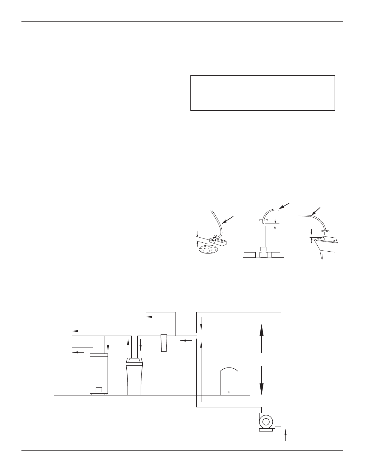
AIR GAP REQUIREMENTS
A drain is needed for regeneration water (See Figure
2). A floor drain, close to the water softener, is preferred. A laundry tub, standpipe, etc. are other drain
options. Secure valve drain hose in place. Leave an
air gap of 1-1/2” between the end of the hose and the
drain. This gap is needed to prevent backflow of
sewer water into the water softener. Do not put the
end of the drain hose into the drain.
1-1/2”
air gap
FLOOR DRAIN
Drain
Hose
1-1/2”
air gap
Drain
Hose
1-1/2”
air gap
LAUNDRY TUBSTANDPIPE
Drain
Hose
FIG. 2
THE PROPER ORDER TO INSTALL WATER TREATMENT EQUIPMENT
Untreated Water to
Cold Water
to House
Hot Water
to House
Outside Faucets
Water
Heater
Softener
Water
Optional
Sediment
Filter
City Water Supply
Pressure
Tank
Well Water Supply
OR
Well
Pump
FIG. 3
6
Installation Requirements
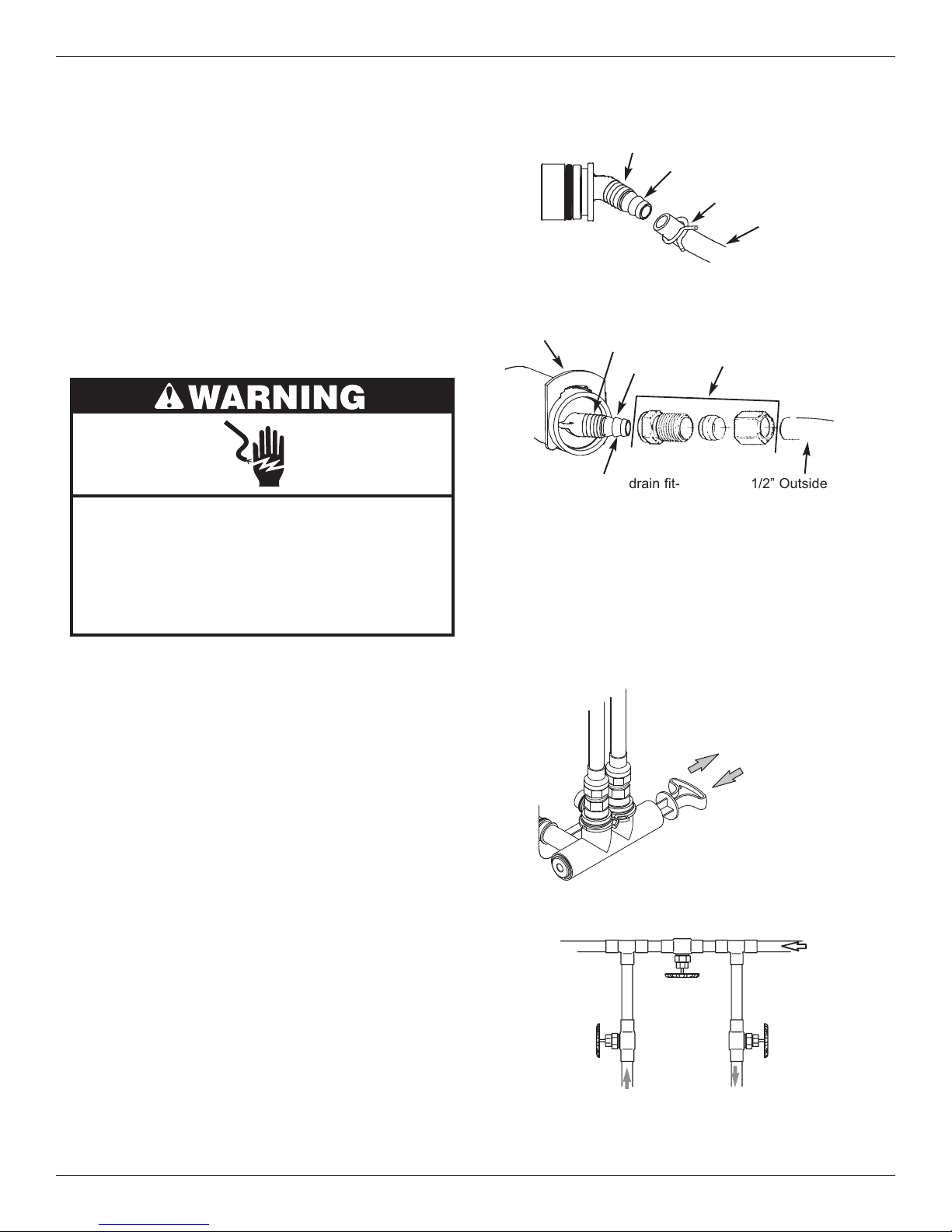
VALVE DRAIN REQUIREMENTS
Using the flexible drain hose (included), measure and
cut to the length needed. Flexible drain hose is not
allowed in all localities (check your plumbing codes). If
local codes do not allow use of a flexible drain hose, a
rigid valve drain run must be used. Purchase a compression fitting (1/4 NPT x 1/2 in. minimum tube) and
1/2" tubing from your local hardware store. Plumb a
rigid drain as needed (See Figure 5).
NOTE: Make the valve drain line as short and direct
as possible.
Electrical Shock Hazard
Prior to installation on metallic plumbing,
securely install two grounding clamps and a
#4 copper wire per installation instructions.
Failure to follow these instructions can result
in death or electrical shock.
1/4” NPT
Thread
Clip
Cut barbs from drain fit-
ting (pull clip to remove
1/4 NPT
Threads
Barbs
fitting from valve)
Barbs for 3/8”
I.D. Tubing
Hose Clamp
Drain Hose
FIG. 4
Compression Fitting.
1/4 NPT x 1/2” O.D.
Tube (not included)
1/2” Outside Dia.
Copper Tube
(not included)
FIG. 5
INLET / OUTLET PLUMBING OPTIONS
Always install either a single bypass valve (provided),
as shown in Figure 6, or, if desired, parts for a 3 valve
bypass system (not included) can be purchased and
assembled, as shown in Figure 7. Bypass valves
allow you to turn off water to the softener for maintenance if needed, but still have water in house pipes.
Pipe fittings must be 3/4” minimum.
Use:
= Copper pipe
= Threaded pipe
= PEX (Crosslinked Polyethylene) pipe
= CPVC plastic pipe
= Other pipe approved for use with potable water
IMPORTANT: Do not solder with plumbing attached to
installation adaptors and single bypass
valve. Soldering heat will damage the
adaptors and valve.
Outlet
Valve
SINGLE BYPASS VALVE
Pull out for “Service”
(Soft water)
Push in for
“Bypass”
3 VALVE BYPASS
Bypass
Valve
From Water
Softener
To Water
Softener
FIG. 6
Inlet
Valve
FIG. 7
7
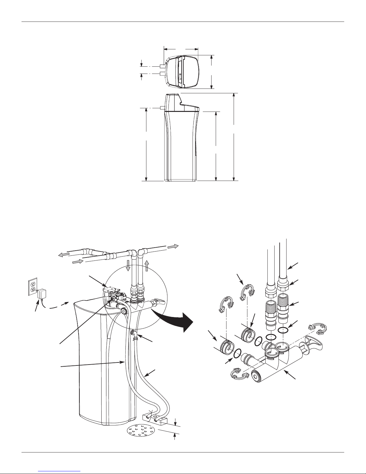
3-3/4”
Dimensions
19”
IN
UT
O
IN – OUT
41-1/2”
18”
47-7/8”
39-1/2”
FIG. 8
To Outside
Faucets
Plug-in
Power
Supply
Valve Drain
Elbow
Valve Drain
Hose*
Hard Water
Water Softener
Valve
To
Controller
Installation Instructions
TYPICAL INSTALLATION
Pipe
ter
Wa
in
a
M
Overflow
Drain Elbow
Salt Storage
Tank Overflow
Hose*
Conditioned
Water
Clips
Outlet
Inlet
Lubricated
O-ring
Pipe
1” NPT Sweat
Adaptor (not
included)
1” NPT
Threaded
Adaptor
O-ring
Single
Bypass Valve
*Do not connect the
water softener valve drain
tubing to the salt storage
tank overflow hose.
Floor Drain
Secure Valve Drain Hose
in place over Floor Drain
NOTE: See “Air Gap Requirements” section.
1-1/2”
air gap
NOTE: Water Softener shown with Salt Lid and
8
Top Cover removed
FIG. 9
 Loading...