

Whirlpool WHES40 User Manual

Whirlpool
Model WHES40
Howto install, operate and
maintain your Demand
Controlled Water Softener
Do not return water softener to store
If you have questions or concerns when
installing, operating or maintaining your
softener, call our toll free number:
1-866-986-3223
Monday - Friday, 8 am - 9 pm EST
•I
i
7262970 (Rev. D 9/22/04)
Product No. 8562922

Table of Contents
Water Softener Safety .......................................................................................................................................... 3
Before You Start .................................................................................................................................................. 3
Inspect Shipment ................................................................................................................................................. 4
Water Softener Dimensions ................................................................................................................................. 5
How a Water Softener Works .............................................................................................................................. 5
Softening Cycle ............................................................................................................................................. 5
Regeneration Cycle........................................................................................................................................ 5
Water Conditioning Information ........................................................................................................................... 6
Water Conditioning ........................................................................................................................................ 6
Installation Requirements .................................................................................................................................... 8
Location Requirements.................................................................................................................................. 8
Tools and Parts Needed................................................................................................................................ 8
Air Gap Requirements ................................................................................................................................... 9
Valve Drain Requirements ............................................................................................................................ 8
Plan the Installation ........................................................................................................................................... 10
Inlet - Outlet Plumbing Options.................................................................................................................... 10
Installation Instructions ..................................................................................................................................... 11
Turn Off Water Supply................................................................................................................................. 11
Install Brine Tank Overflow Elbow............................................................................................................... 11
Move the Water Softener into Place............................................................................................................ 12
Assemble Inlet and Outlet Plumbing ........................................................................................................... 13
Connect Inlet and Outlet Plumbing ............................................................................................................. 13
install Valve Drain Hose .............................................................................................................................. 14
install Salt Storage Tank Overflow Hose .................................................................................................... 14
Test for Leaks............................................................................................................................................... 15
Add Water and Salt to the Salt Storage Tank.............................................................................................. 15
Sanitize the Water Softener/Sanitize After Service..................................................................................... 15
Plug In the Water Softener........................................................................................................................... 15
Program the Water Softener............................................................................................................................... 16
Set Time of Day........................................................................................................................................... 16
Set Water Hardness Number....................................................................................................................... 17
Set Recharge (Regeneration) Time ............................................................................................................ 17
Set Salt lype................................................................................................................................................. 17
Start a Recharge ......................................................................................................................................... 18
Customize Features/Options ............................................................................................................................. 19
Recharge...................................................................................................................................................... 19
Recharge Scheduled / Tonight ................................................................................................................... 19
Set Salt Level .............................................................................................................................................. 19
Tank Light .................................................................................................................................................... 20
Timer “Power-Outage Memory”................................................................................................................... 20
Water Flow Indicator.................................................................................................................................... 20
Salt Efficiency............................................................................................................................................... 20
Clean / Clear Water Iron Removal ............................................................................................................. 21
Clean Feature Minutes ............................................................................................................................... 21
Maximum Days Between Regenerations..................................................................................................... 22
12 or 24 Hour Clock .................................................................................................................................... 22
Routine Maintenance.......................................................................................................................................... 23
Refilling With Salt......................................................................................................................................... 23
Breaking A Salt Bridge................................................................................................................................. 23
Cleaning the Nozzle and Venturi................................................................................................................. 24
Troubleshooting Guide ...................................................................................................................................... 25
Automatic Electronic Diagnostics................................................................................................................. 26
Manual Advance Diagnostics ...................................................................................................................... 26
Manual Advance Regeneration Check ....................................................................................................... 27
Wiring Schematic ............................................................................................................................................... 29
Warranty.............................................................................................................................................................. 29
Softener Components ........................................................................................................................................ 30

Water Softener Safety
Your safety and the safety of others are very important.
We have provided many important safety messages in this manuai and on your appliance. Always read and obey all
safety messages.
This is the safety alert symbol.
This symboi alerts you to potential hazards that can kill or hurt you and others.
All safety messages will follow the safety alert symbol and either the word “DANGER” or
“WARNING." These words mean:
You can be killed or seriously Injured If you don't
ADAHGER
AWARNING
All safety messages will tell you what the potential hazard is^ tell you how to reduce the chance of injury, and tell you
what can happen if the instructions are not followed.
For installations in the Commonwealth of Massachusetts:
Installation by a licensed plumber is required. Plumbing code 248-CMR of the Commonwealth
of Massachusetts must be used for installation.
Immediately follow Instructions.
You can be killed or seriously injured if you don't
follow instructions.
For installations in the state of California:
You must turn the Salt Efficiency Feature setting to ON. This may initiate more frequent re
charges, however, it will operate at 4,()()() grains per pound of salt or higher. To turn on the Salt
Efficiency Feature, follow the instructions in the “Salt Efficiency” section of this manual.
Before You Start
See “Location Requirements” section before installing water softener.
Follow the installation instructions carefully. (Failure to install the water softener properly voids the
warranty.)
Before you begin installation, read this entire manual. Then, obtain all the materials and tools you will
need to make the installation.
Check local plumbing and electrical codes.
Use only lead-free solder and flux for all sweat-solder connections, as required by federal codes.
Use care when handling the water softener. Do not turn upside down, drop, or set on sharp protrusions.
Avoid installing in direct sunlight. Excessive sun heat may cause distortion or other damage to
non-metallic parts.
The water softener requires a minimum water flow of 3 gallons per minute at the inlet. Maximum
allowable inlet water pressure is 125 psi. If daytime pressure is over 80 psi, nighttime pressure may
exceed the maximum. Use a pressure reducing valve if necessary. (Adding a pressure reducing valve
may reduce the flow.) If your home is equipped with a back flow preventer, an expansion tank must
be installed in accordance with local codes and laws.
The water softener works on 24 volt-60 hz electrical power only, supplied by a direct plug-in
transformer (included). Be sure to use the included transformer and plug it into a nominal 120V, 60
cycle household outlet that is properly protected by an ovcrcurrent device such as a circuit breaker or
fuse. If transformer is replaced, use only the authorized service, Class II, 24V lOVA transformer.
This system is not intended to be used for treating water that is microbiologically unsafe or of unknown
quality without adequate disinfection before or after the system.
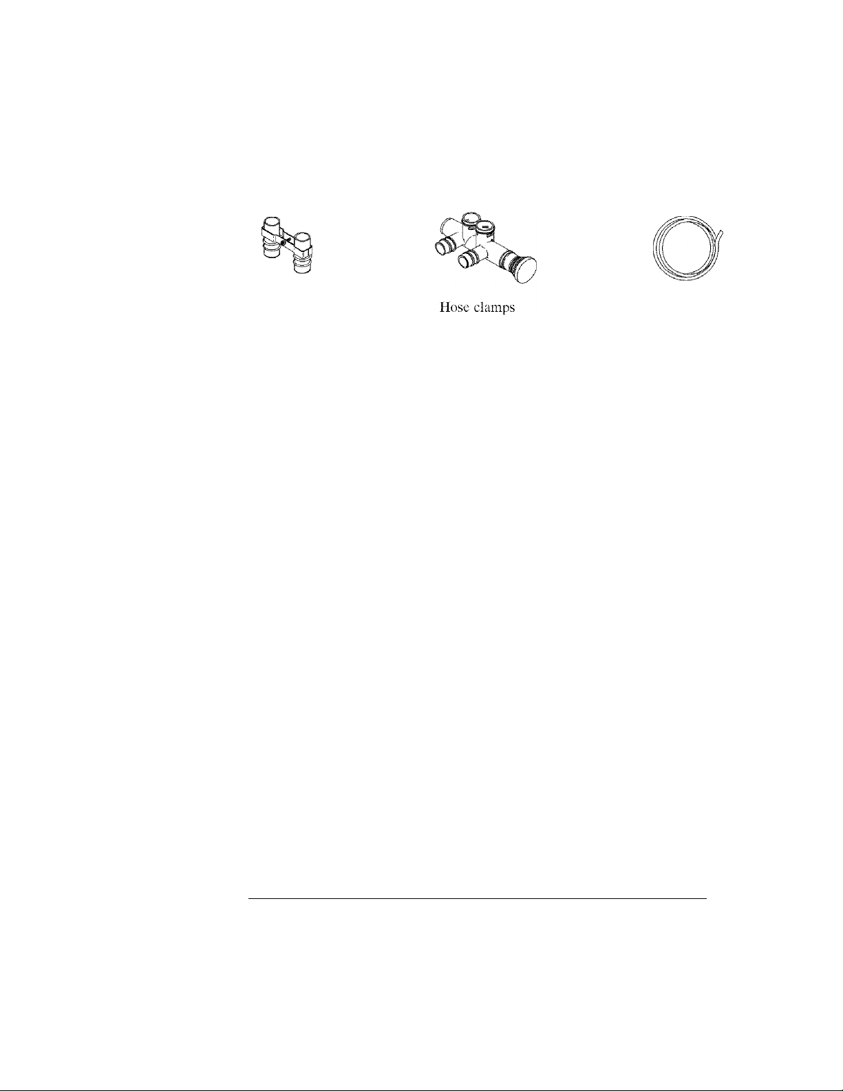
Inspect Shipment
The parts required to assemble and install the water softener arc included with the water softener.
Copper tubes and ground Single valve bypass 20 ft. green drain hose
clamp
Hose adaptor
^ "Si
Drain line adaptor
Copper reducer tubes
O-rings
0 Oo o
Grommet Water hardness test strip
Thoroughly check the water softener for possible shipping damage and parts loss. Also inspect and
note any damage to the shipping carton.
Remove and discard (or recycle) all packing materials. To avoid loss of small parts, we suggest you
keep the small parts in the parts bag until you arc ready to use them.
Do not return the water softener to store.
If you have any questions, or there are missing parts or damage, please call
1 -866“"986-“3223, Monday - Friday, 8 am - 9 pm ESI
Before you call please have your model number, date of purchase, water
conditions and number of people living in your home.
For future reference, enter the following information.
Model No. O ©
Code O
*Water hardness.
----------------------------------------
O on registration decal (located under salt hole cover) Q on shipping carton
------------------------------
____________
gpg **lron content
Serial No. O © ------------------
Installation date
-----------------
___________
ppm
’’’ A hardness test strip is provided with your water softener.
* * Kits arc available at retail hardware stores for testing water hardness and iron content. Some retail
stores will also test your water for a fee.
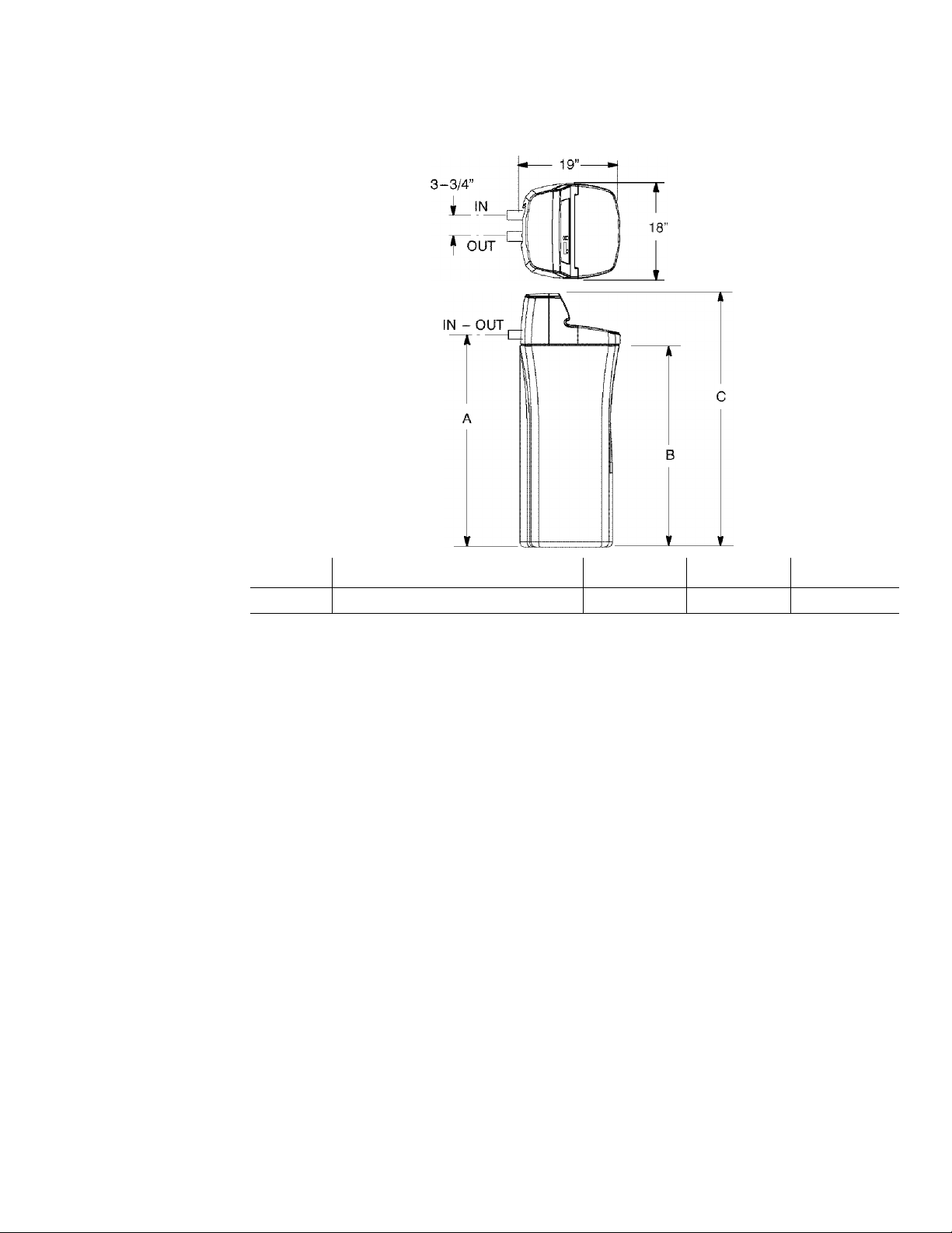
Water Softener Dimensions
MODEL NOMINAL RESIN TANK SIZE A B C
WHES40 10” D!A. X40”
How a Water Softener Works
Softening Cycle
When the water softener is providing soft water, it is called “service” or the “softening cycle”. During
this cycle, hard water flows from the main water pipe in the household into the water softener. Inside
the resin tank is a bed made up of thousands of tiny, plastic resin beads. As hard water passes through
the bed, each bead attracts and holds the hardness minerals. Water without the hardness minerals (soft
water) flows from the water softener to the rest of the house.
Regeneration Cycle
Eventually the beads become coated with calcium or magnesium ions. At this point, the water softener
needs to replenish the beads with sodium ions. This process is called “regeneration”.
Regeneration occurs when the resin beads are washed with a strong salt water solution. The sodium
forces the calcium and magnesium ions to be released where they are then discharged as waste during
the regeneration cycle. The beads arc then ready to once again collect the hardness minerals (calcium
and magnesium) from the water. Regeneration consists of five cycles; brine fill, brining, brine rinse,
backwash and fast rinse. The total time of the regeneration cycle is approximately two hours.
41-1/2” 39-1/2”
47-7/8”
Water Conditioning Information
Water Conditioning
Water conditioning is the treatment of four general conditions. These are:
Hardness
Iron
Acidity
Sediments
1. Hardness is a term to describe the presence of calcium and magnesium minerals in water. A
chemical analysis accurately measures the amount of minerals in grain weight. For example, one
gallon of water with 5 grains per gallon (gpg) hardness has dissolved minerals, that if solidified,
about equals the size of one ordinary aspirin tablet. One gallon of water, 25 gpg hard, has a mineral
content equal in size to 5 aspirin tablets. Water hardness varies greatly across the country. It
generally contains from 3 to 100 gpg.
Hardness minerals combine with soap to make a soap curd. The curd greatly reduces the cleaning
action of soap. Precipitated hardness minerals form a crust on cooking utensils, appliances, and
plumbing fixtures. Even the tastes of foods are affected. A water softener removes the hardness
minerals to eliminate these effects, and others.
IMPORTANT: Water softeners using sodium chloride (salt) for regeneration add sodium to the
water. Persons on sodium restricted diets should consider the added sodium as part of their overall
intake. Water softeners using potassium chloride (salt) for regeneration add sodium to the water.
Persons on potassium restricted diets should consider the added potassium as part of their overall
intake.
Factor into your diet the amount of sodium or potassium shown below, based on your water
hardness and consumption.
Sodium Added to Water from Cation Exchange Softening
Initial Water Hardness
Grains per Gallon
1
5 37 62.9
6
7
8 60
9 68 115.6
10 75 127.5
15
20 150 255
30 225 382,5
40 300 510
Sodium added by Cation
Exchange Softening of Water*
Milligrams Na+/qt. Milligrams K+/qt.
7.5 12.75
44
52 88.4
112 190.4
Potassium added by Cation
Exchange Softening of Water**
74.8
102
*If your water supply is 15 grains hard and you drank 3 quarts of softened water you would
consume 335 milligrams of sodium. That is equivalent to eating 2-1/2 slices of white bread.
*'®'Onc large banana, about 9 inches in length, has approximately 600 milligrams of potassium.

2. Iron in water can cause stains on clothing and plumbing fixtures. It can negatively affect the taste
of food, drinking water, and other beverages. Iron in water is measured in parts per million (ppm).
The total* ppm of iron, and type or types*, is determined by chemical analysis. Four different types
of iron in water are:
Ferrous (clear water).
Ferric (red water).
Bacterial and organically bound iron.
Colloidal and inorganically bound iron (ferrous or ferric).
* Water may contain one or more of the four types of iron and any combination of these. Total iron
is the sum of the contents.
Ferrous (clear water) iron is soluble and dissolves in water. This water softener will remove
moderate amounts of this type of iron (see specifications). Ferrous (clear water) iron is usually
detected by taking a sample of water in a clear bottle or glass. Immediately after taking, the sample
is clear. As the water sample stands, it gradually clouds and turns slightly yellow or brown as air
oxidizes the iron. This usually occurs in 15 to 30 minutes.
When using the softener to remove Ferrous (clear water) iron, add 5 grains to the hardness setting
for every 1 ppm of Ferrous (clear water) iron. See “Set Water Hardness Number” section.
Ferric (red water), andbacterial and organically bound irons are insoluble. This water softener will
not remove ferric or bacterial iron. This iron is visible immediately when drawn from a faucet
because it has oxidized before reaching the home. It appears as small cloudy yellow, orange, or
reddish suspended particles. After the water stands for a period of time, the particles settle to the
bottom of the container. Generally these irons arc removed from water by filtration. Chlorination
is also recommended for bacterial iron.
Colloidal and inorganically bound iron is of ferric or ferrous form that will not filter or exchange
out of water. This water softener will not remove colloidal iron. In some instances, treatment may
improve colloidal iron water. Colloidal iron water usually has a yellow appearance when drawn.
After standing for several hours, the color persists and the iron does not settle, but remains
suspended in the water.
3. Acidity or acid water is caused by carbon dioxide and hydrogen sulfide. This water softener will
not improve an acid condition in water. Acid water can be corrosive to plumbing, plumbing
fixtures, water heaters, and other water using appliances. In can also damage and cause premature
failure of seals, diaphragms, etc., in water handling equipment.
A chemical analysis is needed to measure the degree of acidity in water. This is called the pH of
water. Water testing below 6.9 pH is acidic. The lower the pH reading, the greater the acidity. A
neutralizer filter or a chemical feed pump are usually recommended to treat acid water.
4. Sediment is fine, foreign material particles suspended in water. This water softener will not
remove sediment. This material is most often clay or silt. Extreme amounts of sediment may give
the water a cloudy appearance. A sediment filter installed ahead of the water softener normally
corrects this situation.
Installation Requirements
Tools and Parts Needed
Assemble the required tools before starting installation. Read and follow the instructions provided with
any tools listed here.
Screwdriver • Tape Measure
Pliers
If using Soldered Copper Pipe
Tubing cutter
Propane torch
Misc. copper pipe fittings
If using Threaded Pipe
Pipe cutter or hacksaw
Threading tool
If using CPVC Plastic
Pipe cutter
Hacksaw
Adjustable wrench
If using Other
Other pipe and fittings suitable for potable water supply as required by piping system
manufacturer and local codes and/or ordinances.
Lead-free solder and flux
Emery cloth, sandpaper or steel wool
Pipe joint compound
Misc. threaded pipe fittings
Solvent cement
Primer
Misc. CPVC pipe fittings
Location Requirements
Consider all of the following when selecting an installation location for the water softener.
• Do not locate the water softener where freezing temperatures occur. Do not attempt to
treat water over 120° F. Freezing, or hot water damage voids the warranty.
• To condition all water in the home, install the water softener close to the water supply
inlet, and before all other plumbing connections, except outside water pipes. Outside
faucets should remain on hard water to avoid wasting conditioned water and salt.
• A nearby drain is needed to carry away regeneration discharge (drain) water. Use a floor
drain, laundry tub, sump, standpipe, or other options (check your local codes). See “Air
Gap Requirements” and “Valve Drain Requirements” sections.
• The water softener works on 24 volt-60 hz electrical power only, supplied by a direct
plug-ill transformer (included). Provide an electrical outlet in accordance with NEC and
local codes.
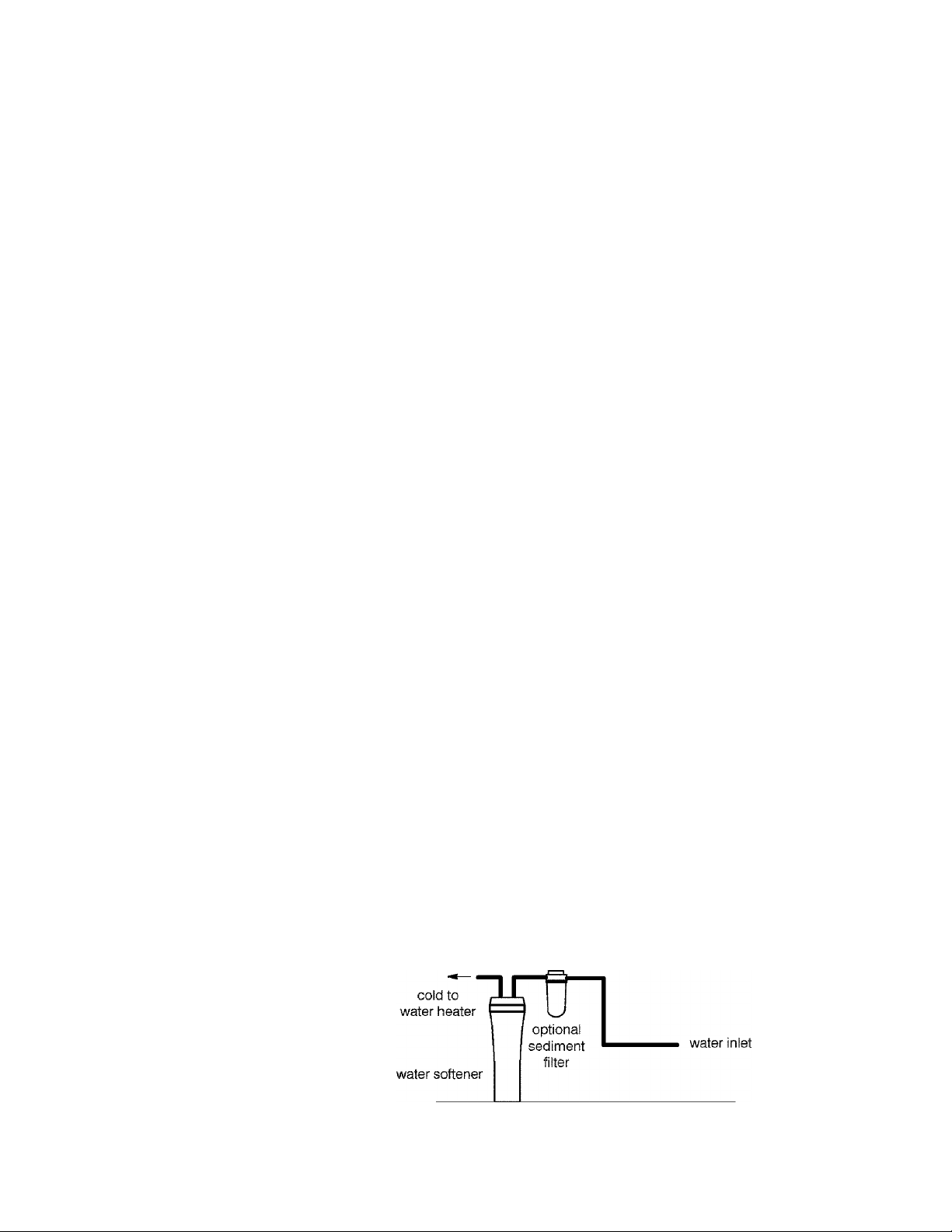
• Always install the water softener between the water heater and water inlet. Any other
installed water conditioning equipment should be installed between the water softener
and the water inlet (sec Figure 1 below).
Figure 1
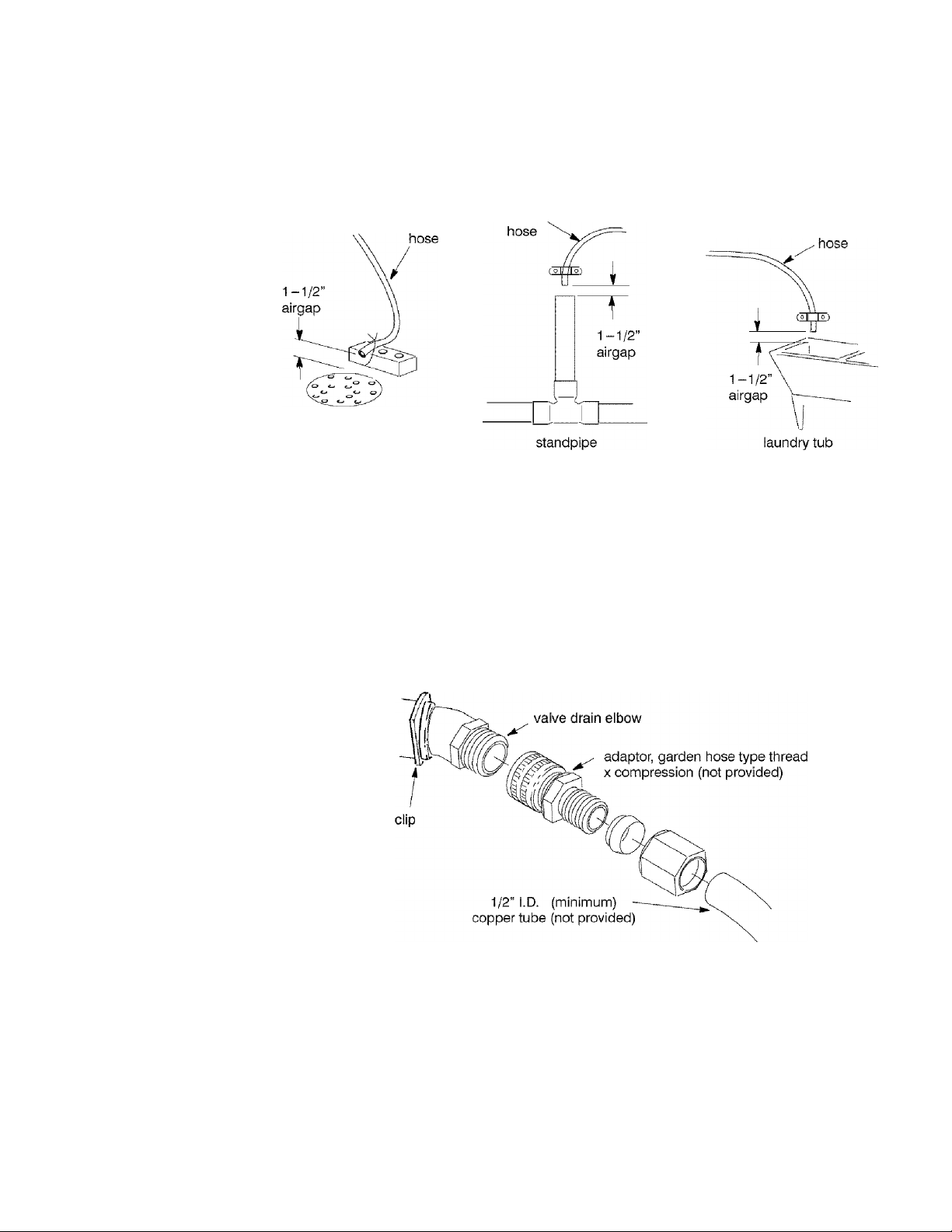
Air Gap Requirements
A drain is needed for regeneration discharge water. A floor drain, close to the water softener, is
preferred. A laundry tub, standpipe, etc., are other drain options. Secure valve drain hose in place.
floor drain
Figure 2
Valve Drain Requirements
Use the flexible green drain hose, that is included, measure and cut to the length needed. Flexible drain
hose is not allowed in all localities (check your plumbing codes). If local codes do not allow use of a
flexible drain hose, a rigid valve drain run must be used. Buy a compression fitting (garden hose threads
X 1/2 in. minimum tube) and 1/2” tubing from your local hardware store. Then plumb a rigid drain as
needed (sec Figure 3).
NOTE: Avoid long drain hose runs, or elevating the hose more than 8’ above the floor. Make
drain
drain
the water softener valve drain as short and direct as possible.
drain
Figure 3

Plan the Installation
Inlet - Outlet Plumbing Options
Always install either a single bypass valve (provided) or, if desired, parts for a 3 valve bypass system
(not included) can be purchased and assembled, as shown in Figure 4. Bypass valves allow you to turn
off water to the softener for maintenance if needed, but still have water in house pipes.
Single valve bypass
• Pipe and fittings must be 3/4” minimum.
Use either:
• Copper pipe
• CPVC plastic pipe
3 valve bypass
Figure 4
Threaded pipe
Other pipe approved for use with potable water
¡0
Installation Instructions
Turn Off Water Supply
1. Close the main water supply valve, near the well pump or water meter.
2. Open all faucets to drain all water from the house pipes.
NOTE: Be sure not to drain water from the water heater, as damage to the water heater
elements could result.
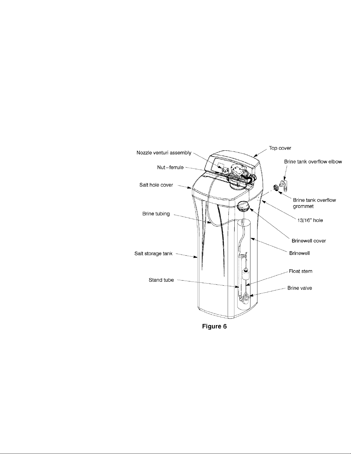
Install the Brine Tank Overflow Elbow
Install the brine tank overflow grommet and elbow in the 13/16” diameter hole in the back of the salt
storage tank sidewall.
NOTE: The brine tank overflow elbow accepts either 1/2” or 3/8” I. D. hose.
U
 Loading...