

Whirlpool WHES Installation Instructions Manual
Installation Instructions
WHES Series
Demand Controlled
Water Softener
For a detailed owner’s manual,
including specifications,
programming and parts list, go to:
www.whirlpoolwatersofteners.com
or call 1-866-986-3223
Do not return water softener to store
If you have any questions or concerns when
installing, operating or maintaining your water
softener, call our toll free number:
1-866-986-3223
Monday- Friday, 8 AM - 7 PM EST or visit
www.whirlpoolwatersofteners.com
When you call, please be prepared to provide
the model and serial number of your product,
found on the rating decal, typically located on
the rim below the salt lid hinges.
Systems tested and certified by NSF International
against NSF/ANSI Standard 44
for hardness reduction and efficiency,
and certified to NSF/ANSI Standard 372.
Systems tested and certified by the Water Quality
Association against CSA B483.1.
English
Manufactured and warranted by
Ecodyne Water Systems
1890 Woodlane Drive
Woodbury, MN 55125
1
7345485 (Rev. A 9/30/14)
Water Softener Safety
Your safety and the safety of others are very important.
We have provided many safety messages in this manual and on your appliance. Always read and obey all safety
messages.
This is the safety alert symbol.
This symbol alerts you to potential hazards that can kill or hurt you and others.
All safety messages will follow the safety alert symbol and either the word “DANGER” or “WARNING”
These words mean:
You can be killed or seriously injured if you don’t
immediately follow instructions.
You can be killed or seriously injured if you don’t
follow instructions.
All safety messages will tell you what the potential hazard is, tell you how to reduce the chance of injury, and tell
you what can happen if the instructions are not followed.
Before You Start
= The water softener requires a minimum water flow
English
= Do not use this system to treat water that is micro-
LOCATION REQUIREMENTS
Consider all of the following when selecting an installation location for the water softener.
= Do not locate the water softener where freezing
= To condition all water in the home, install the water
= A nearby drain is needed to carry away regenera-
of 3 gallons per minute at the inlet. Maximum
allowable inlet water pressure is 125 psi. If daytime
pressure is over 80 psi, nighttime pressure may
exceed the maximum. Use a pressure reducing
valve if necessary (Adding a pressure reducing
valve may reduce the flow). If your home is
equipped with a back flow preventer, an expansion
tank must be installed in accordance with local
codes and laws.
biologically unsafe or of unknown quality without
adequate disinfection upstream or downstream of
the system.
temperatures occur. Do not attempt to treat water
over 120ºF. Freezing temperatures or hot water
damage voids the warranty.
softener close to the water supply inlet, and
upstream of all other plumbing connections, except
outside water pipes. Outside faucets should remain
on hard water to avoid wasting conditioned water
and salt.
tion discharge (drain) water. Use a floor drain,
laundry tub, sump, standpipe, or other options
(check your local codes). See "Air Gap
Requirements" and "Valve Drain Requirements"
sections.
= The water softener works on 28V DC electrical
power, supplied by a direct plug-in power supply
(included). Be sure to use the included power supply and plug it into a nominal 120V, 60 Hz household outlet that is in a dry location only, grounded
and properly protected by an overcurrent device
such as a circuit breaker or fuse.
= Always install the water softener between the water
inlet and water heater. Any other installed water
conditioning equipment should be installed between
the water inlet and water softener (See Figure 6).
= Avoid installing in direct sunlight. Excessive sun
heat may cause distortion or other damage to nonmetallic parts.
PLUMBING CODES
All plumbing must be completed in accordance with
national, state and local plumbing codes.
In the state of Massachusetts: The Commonwealth
of Massachusetts plumbing code 248-CMR shall
be adhered to. A licensed plumber shall be used
for this installation.
2
Before You Start
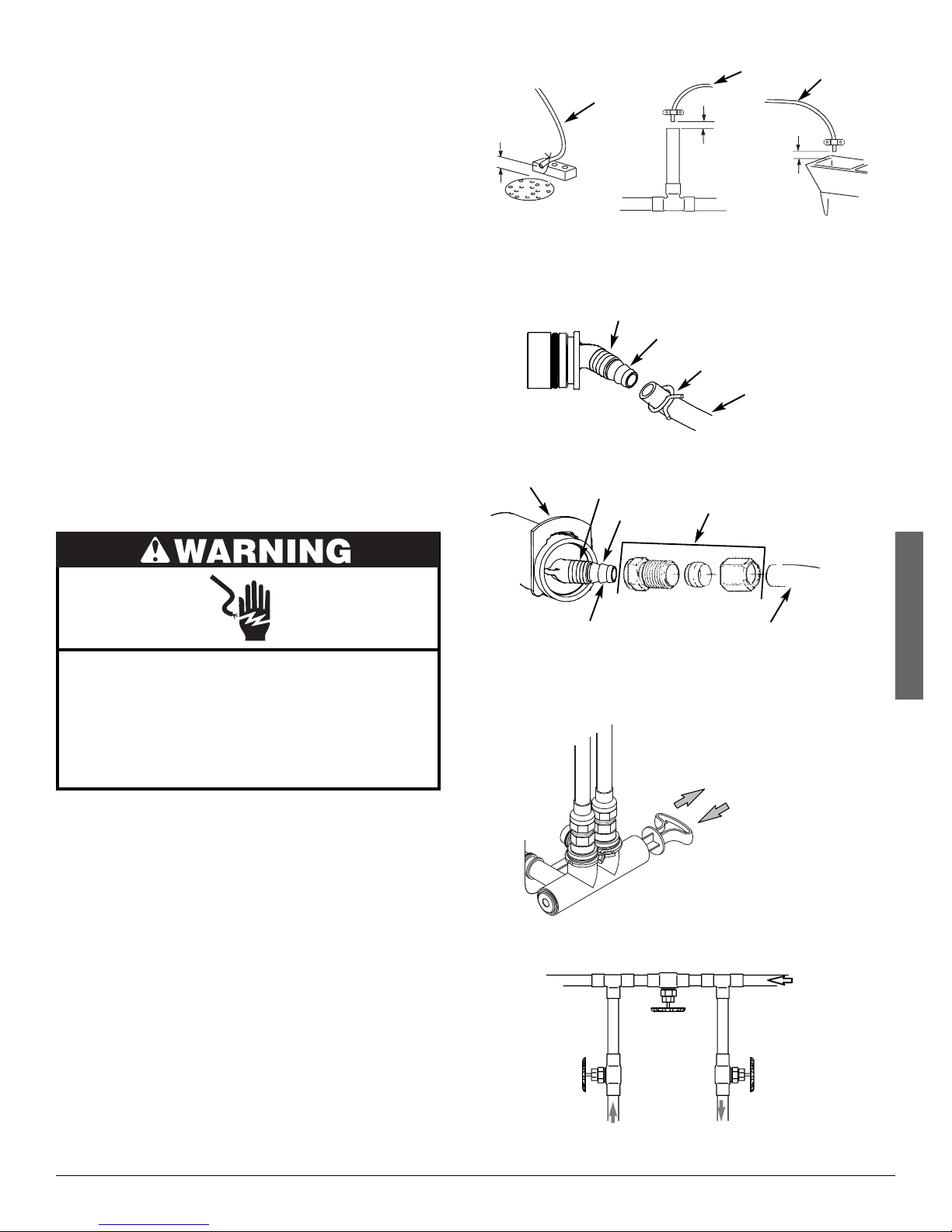
AIR GAP REQUIREMENTS
A drain is needed for regeneration water (See Figure
1). A floor drain, close to the water softener, is
preferred. A laundry tub, standpipe, etc. are other
drain options. Secure valve drain hose in place.
Leave an air gap of 1-1/2” between the end of the
hose and the drain. This gap is needed to prevent
backflow of sewer water into the water softener. Do
not put the end of the drain hose into the drain.
VALVE DRAIN REQUIREMENTS
Using the flexible drain hose (included), measure and
cut to the length needed. Flexible drain hose is not
allowed in all localities (check your plumbing codes). If
local codes do not allow use of a flexible drain hose, a
rigid valve drain run must be used. Purchase a compression fitting (1/4 NPT x 1/2 in. minimum tube) and
1/2" tubing from your local hardware store. Plumb a
rigid drain as needed (See Figure 3).
NOTE: Make the valve drain line as short and direct
as possible.
1-1/2”
air gap
FLOOR DRAIN
Clip
1/4 NPT
Threads
Drain
Hose
1/4” NPT
Thread
Barbs
1-1/2”
air gap
Barbs for 3/8”
I.D. Tubing
Hose Clamp
Compression Fitting.
1/4 NPT x 1/2” O.D.
Tube (not included)
Drain
Hose
1-1/2”
air gap
LAUNDRY TUBSTANDPIPE
Drain Hose
Drain
Hose
FIG. 1
FIG. 2
Electrical Shock Hazard
Prior to installation on metallic plumbing,
securely install two grounding clamps and a
#4 copper wire per installation instructions.
Failure to follow these instructions can result
in death or electrical shock.
INLET / OUTLET PLUMBING OPTIONS
Always install either a single bypass valve (provided),
as shown in Figure 4, or, if desired, parts for a 3 valve
bypass system (not included) can be purchased and
assembled, as shown in Figure 5. Bypass valves
allow you to turn off water to the softener for maintenance if needed, but still have water in house pipes.
Pipe fittings must be 3/4” minimum.
Use:
= Copper pipe
= Threaded pipe
= PEX (Crosslinked Polyethylene) pipe
= CPVC plastic pipe
= Other pipe approved for use with potable water
IMPORTANT: Do not solder with plumbing attached to
installation adaptors and single bypass
valve. Soldering heat will damage the
adaptors and valve.
Cut barbs from drain fitting (pull clip to remove
fitting from valve)
SINGLE BYPASS VALVE
3 VALVE BYPASS
Outlet
Valve
From Water
Softener
1/2” Outside Dia.
Copper Tube
(not included)
Bypass
Valve
To Water
Softener
English
FIG. 3
Pull out for “Service”
(Soft water)
Push in for
“Bypass”
FIG. 4
Inlet
Valve
FIG. 5
3
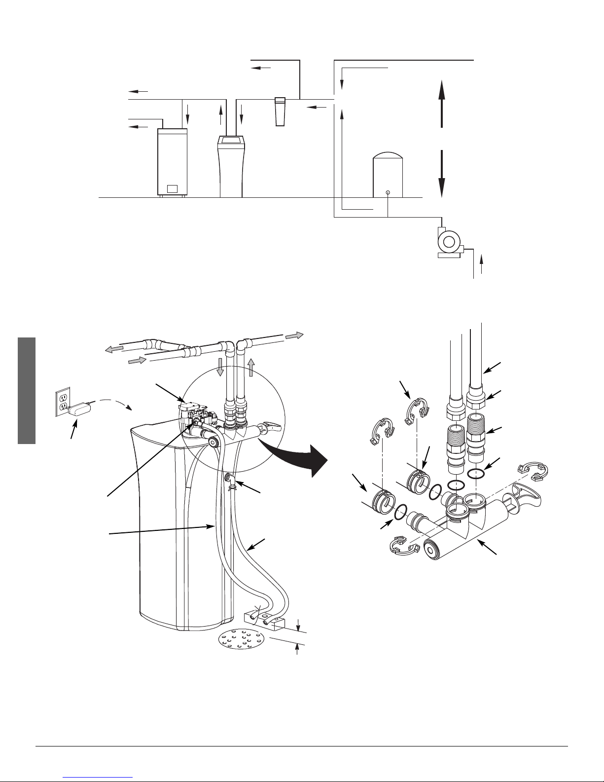
THE PROPER ORDER TO INSTALL WATER TREATMENT EQUIPMENT
To Outside
English
Plug-in
Power
Supply
Cold Water
to House
Hot Water
to House
Faucets
Water Softener
Controller
To
Untreated Water to
Water
Heater
Hard Water
Valve
Outside Faucets
Water
Softener
Main Water Pipe
Optional
Pressure
Sediment
Filter
TYPICAL INSTALLATION
Conditioned
Water
Inlet
City Water Supply
Tank
OR
Well Water Supply
Well
Pump
Clips
Outlet
FIG. 6
Pipe
1” NPT Sweat
Adaptor (not
included)
1” NPT
Threaded
Adaptor
O-ring
Valve Drain
Elbow
Valve Drain
Hose*
*Do not connect the
water softener valve drain
tubing to the salt storage
tank overflow hose.
Questions? Call Toll Free 1-866-986-3223 Monday- Friday, 8 AM - 7 PM EST
or visit www.whirlpoolwatersofteners.com
When you call, please be prepared to provide the model and serial number,
found on the rating decal, typically located on the rim below the salt lid hinges.
Floor Drain
Overflow
Drain Elbow
Salt Storage
Tank Overflow
Hose*
Secure Valve Drain Hose
in place over Floor Drain
4
1-1/2”
air gap
Lubricated
O-ring
Single
Bypass Valve
NOTE: See “Air Gap Requirements” section.
NOTE: Water Softener shown with Salt Lid and
Top Cover removed
FIG. 7
Installation Instructions
TURN OFF WATER SUPPLY
1. Close the main water supply valve, located near the
well pump or water meter.
2. Open all faucets to drain all water from house pipes.
NOTE: Be sure not to drain water from the water
heater, as damage to the water heater elements could result.
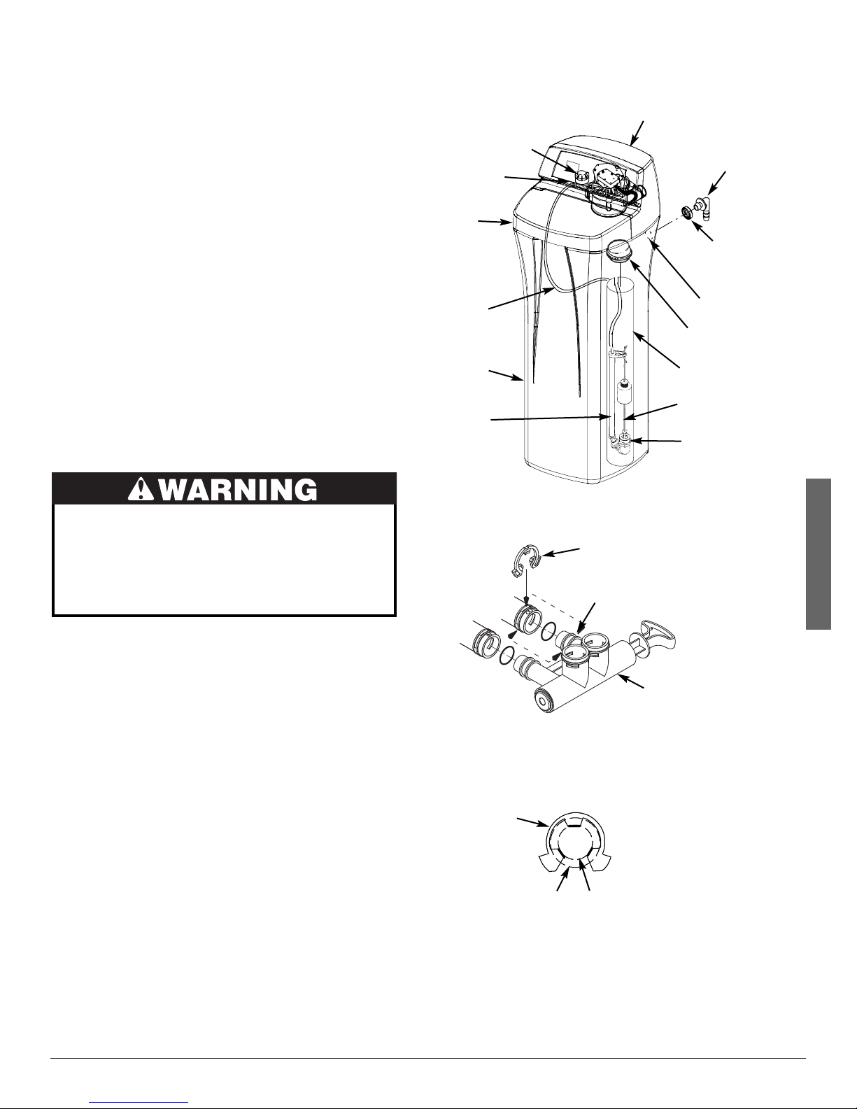
INSTALL THE BRINE TANK OVERFLOW
ELBOW
Install the brine tank overflow grommet and elbow in
the 13/16” diameter hole in the back of the salt storage
tank sidewall.
NOTE: The brine tank overflow elbow accepts either
1/2” or 3/8” I.D. hose.
MOVE THE WATER SOFTENER INTO PLACE
Ferrule
Salt
Lid
Brine
Tubing
Salt
Storage
Tank
Stand
Tube
Nozzle
Venturi
Assembly
Nut -
Top Cover
Brine Tank
Overflow
Elbow
Brine Tank
Overflow
Grommet
13/16” Hole
Brinewell
Cover
Brinewell
Float Stem
Brine
Valve
FIG. 8
Excessive Weight Hazard
Use two or more people to move and install
water softener.
Failure to do so can result in back or other
injury.
1. Move the water softener into the desired location.
Set it on a solid, level surface.
IMPORTANT: Do not place shims directly under the
salt storage tank to level the softener.
The weight of the tank, when full of
water and salt, may cause the tank to
fracture at the shim.
2. Visually check and remove any debris from the
water softener valve inlet and outlet ports.
3. Make sure the turbine assembly spins freely in the
"out" port of the valve.
4. If not already done, put a light coating of silicone
grease on the single bypass valve o-rings.
5. Push the single bypass valve into the softener valve
as far as it will go. Snap the two large holding clips
into place, from the top down as shown in Figures 9
& 10.
IMPORTANT: Be sure the clips snap firmly into place
so the single bypass valve will not pull
out.
Clip
Channel
Single Bypass Valve
FIG. 9
CORRECT ASSEMBLY
Clip
Outside diameter
of water softener
valve inlet & outlet
NOTE: Be sure all 3 tabs of the clip go through the matching
holes on the water softener valve inlet or outlet, and
fully into the channel on the single bypass valve.
Make sure that the tabs are fully seated.
Outside diameter
of clip channel on
single bypass valve
FIG. 10
English
5
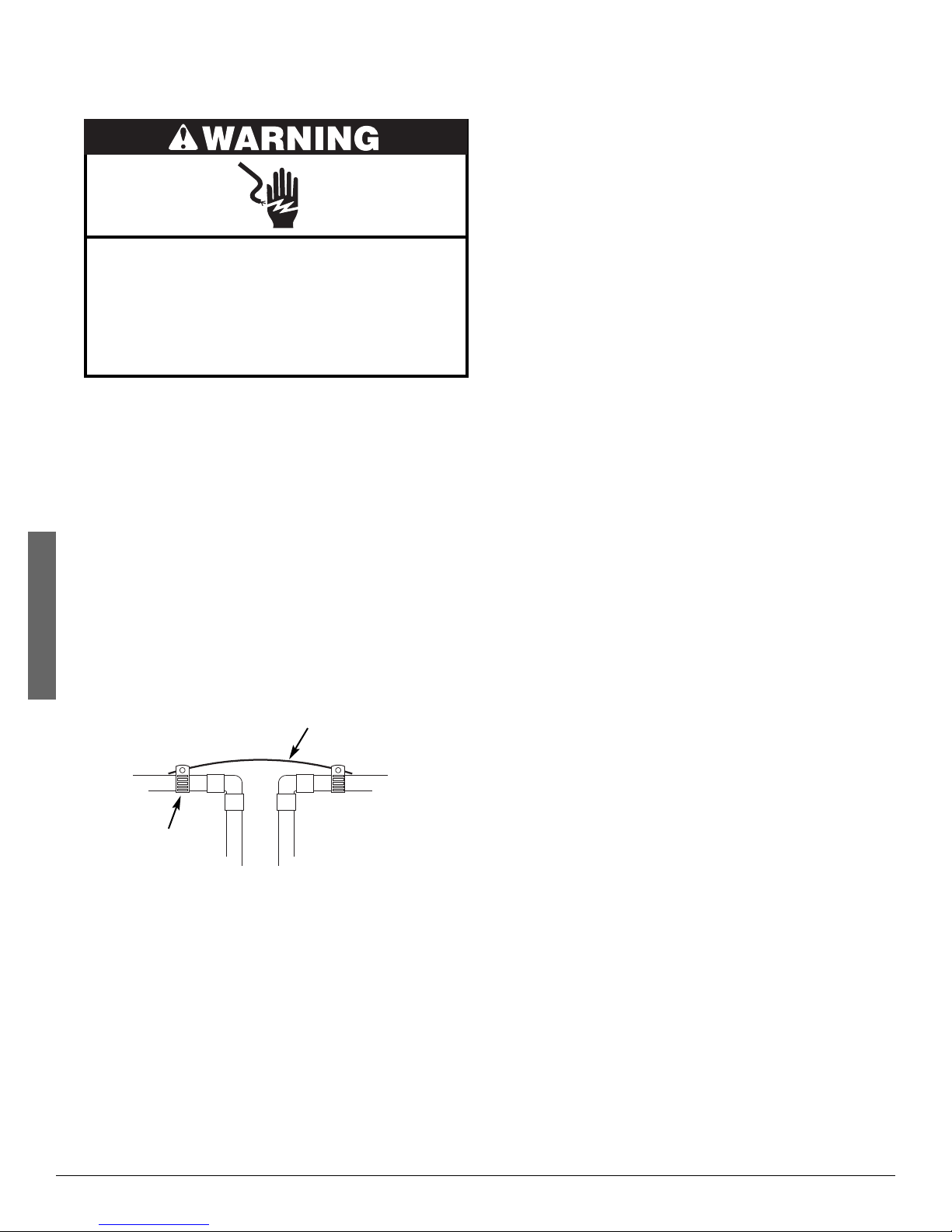
GROUNDING INFORMATION
(for Installations on Metal Pipe)
The house main incoming water pipe is often used to
ground electrical outlets in the home. Grounding protects you from electrical shock. Installing the water
softener with a plastic bypass valve will break this
ground. Before beginning installation, purchase and
securely install two grounding clamps and a #4 copper
wire across the location where the softener will be,
English
tightly clamping it at both ends, as shown in Figure 11.
NOTE: Check local plumbing and electrical codes
Installation Instructions
Electrical Shock Hazard
Prior to installation on metallic plumbing,
securely install two grounding clamps and a
#4 copper wire per installation instructions.
Failure to follow these instructions can result
in death or electrical shock.
for proper installation of the ground wire.
The installation must conform to them. In
Massachusetts, plumbing codes of
Massachusetts shall be conformed to.
Consult with your licensed plumber.
Complete the inlet and outlet plumbing for the type of
pipe you will be using.
INSTALL VALVE DRAIN HOSE
1. Measure, cut to needed length and connect the 3/8"
drain line (provided) to the water softener valve
drain fitting. Use a hose clamp to hold the hose in
place.
NOTE: Make the valve drain line as short and direct
as possible.
IMPORTANT: If codes require a rigid drain line see
“Valve Drain requirements" section.
2. Route the drain hose or copper tubing to the floor
drain. Secure drain hose. This will prevent “whipping'' during regenerations. See “Air Gap
Requirements" section.
INSTALL SALT STORAGE TANK OVERFLOW
HOSE
1. Measure, cut to needed length and connect the 3/8"
drain line (provided) to the salt storage tank overflow elbow and secure in place with a hose clamp.
2 Route the hose to the floor drain, or other suitable
drain point no higher than the drain fitting on the salt
storage tank (This is a gravity drain). If the tank
overfills with water, the excess water flows to the
drain point. Cut the drain line to the desired length
and route it neatly out of the way.
IMPORTANT: For proper operation of the water soften-
er, do not connect the water softener
valve drain tubing to the salt storage
tank overflow hose.
Ground Wire
(not included)
Clamp
(2 - not included)
FIG. 11
COMPLETE INLET AND OUTLET PLUMBING
Measure, cut, and loosely assemble pipe and fittings
from the main water pipe to the inlet and outlet ports of
the water softener valve. Be sure to keep fittings fully
together, and pipes squared and straight.
Be sure hard water supply pipe goes to the water softener valve inlet side.
NOTE: Inlet and outlet are marked on the water softener
valve. Trace the water flow direction to be sure
hard water is to inlet.
IMPORTANT: Be sure to fit, align and support all plumb-
ing to prevent putting stress on the water
softener valve inlet and outlet. Stress
from misaligned or unsupported plumbing
may cause damage to the valve.
TEST FOR LEAKS
To prevent air pressure in the water softener and
plumbing system, complete the following steps in
order:
1. Fully open two or more softened cold water faucets
close to the water softener, located downstream
from the water softener.
2. Place the bypass valve (single or 3 valve) into the
"bypass" position. See Figures 4 & 5.
3. Slowly open the main water supply valve. Run
water until there is a steady flow from the opened
faucets, with no air bubbles.
4. Place bypass valve(s) in "service" or soft water posi-
tion as follows:
= Single bypass valve: Slowly move the valve stem
toward "service," pausing several times to allow
the water softener to fill with water.
= 3 valve bypass: Fully close the bypass valve and
open the outlet valve. Slowly open the inlet
valve, pausing several times to allow the water
softener to fill with water.
5. After about three minutes, open a hot water faucet
until there is a steady flow and there are no air bubbles, then close this faucet.
6. Close all cold water faucets and check for leaks at
the plumbing connections that you made.
6
Installation Instructions
ADD WATER AND SALT TO THE SALT
STORAGE TANK
Excessive Weight Hazard
Use two or more people to move and lift salt
bags.
Failure to do so can result in back or other
injury.
1. Using a container, add about three gallons of clean
water into the salt storage tank.
2. Add salt to the storage tank. Use nugget, pellet or
coarse solar salts with less than 1% impurities.
PLUG IN THE POWER SUPPLY
During installation, the water softener wiring may be
moved or jostled from place. Be sure all leadwire connectors are secure on the back of the electronic board
and be sure all wiring is away from the valve gear and
motor area, which rotates during regenerations.
1. Plug the power supply into an electrical outlet that is
not controlled by a switch.
NOTE: The water heater is filled with hard water and,
as hot water is used, it will refill with conditioned water. In a few days, the hot water will
be fully conditioned. To have fully conditioned
hot water immediately, wait until the initial
recharge is over. Then, drain the water heater
(following instructions for water heater) until
water runs cold.
PROGRAMMING THE SOFTENER
Lift the salt lid and follow the instructions on the decal
to program the following into the electronic controller:
= Current time of day
= Hardness of your water supply
= Time of day when automatic recharges will begin
= Type of salt you will be using (only on select models)
NOTE: You can find complete instructions for program-
ming the softener and customizing features of
the electronic controller in the owner’s manual.
Go to www.whirlpoolwatersofteners.com
or call 1-866-986-3223.
SANITIZE THE WATER SOFTENER /
SANITIZE AFTER SERVICE
1. Open salt lid, remove the brinewell cover and pour
about 3 oz. (6 tablespoons) of household bleach
into the softener brinewell. Replace the brinewell
cover.
2 Make sure the bypass valve(s) is in the “service”
(open) position.
3 Start a recharge (regeneration) by pressing and hold-
ing for 3 seconds the RECHARGE button on the faceplate.
4. After the recharge has completed, fully open a cold
water faucet, downstream from the softener, and
allow 50 gallons of water to pass through the system. This should take at least 20 minutes. Close
the faucet.
ADDING SALT
Lift the salt lid and check the salt storage level frequently. If the water softener uses all the salt before
you refill it, you will experience hard water. Until you
have established a refilling routine, check the salt
every two or three weeks. Always add if less than 1/4
full. Be sure the brinewell cover is on.
NOTE: If using potassium chloride (KCl), do not fill
above level 4 on the brinewell scale.
NOTE: In humid areas, it is best to keep the salt stor-
age level lower, and to refill more often to avoid
salt “bridging”.
Recommended Salt: Nugget, pellet or coarse solar
salts with less than 1% impurities.
Salt Not Recommended: Rock salt, high in impurities,
block, granulated, table, ice melting, ice cream making
salts, etc.
English
In the state of California: You must turn the Salt
Efficiency Feature setting to ON. This may initiate
more frequent recharges. However, it will operate
at 4,000 grains per pound of salt or higher. To turn
on the Salt Efficiency Feature, follow the instructions in the “Salt Efficiency” section of the owner’s
manual.
TANK LIGHT (Only on select models)
The water softener is equipped with a tank light for
viewing the salt level in the brine tank. Push the tank
light button on the electronic control once, and the tank
light will turn on. Pushing the tank light button again
will turn the light off. The tank light will automatically
turn off after a period of four minutes if the tank light
button is not used to turn it off.
7

EXTEND YOUR WARRANTY:
Use Whirlpool
®
WHE-WSC Water Softener Cleanser
The factory warranty for your water softener is shown below. The one year full warranty period on parts and labor
can be extended to two years from the date of purchase if you use Whirlpool
on your system. Use one bottle of Whirlpool
from the date of purchase of the water softener. Retain proof of purchase of Whirlpool
Cleanser to validate any warranty claim during the second year. Use of any water softener additive other than
Whirlpool
English
®
®
WHE-WSC Water Softener Cleanser, as directed, every four months
®
WHE-WSC will not provide extended warranty coverage.
WHE-WSC Water Softener Cleanser
®
WHE-WSC Water Softener
WATER SOFTENER WARRANTY
Warrantor: Ecodyne Water Systems, 1890 Woodlane Drive, Woodbury, MN 55125
Warrantor guarantees, to the original owner, that:
One Year Full Warranty:
● For a period of one (1) year from the date of purchase, all parts will be free from defects in materials and workmanship and will perform their normal functions.
● For a period of one (1) year from the date of purchase, labor to repair or replace any part deemed to be defective
in materials or workmanship, will be provided at no additional cost.
Limited Warranties:
● For a period of ten (10) years from the date of purchase, the salt storage tank and fiberglass mineral tank will not
rust, corrode, leak, burst, or in any other manner, fail to perform its proper functions.
● For a period of three (3) years from the date of purchase, the electronic control board will be free of defects in
materials and workmanship and will perform its normal functions.
If, during such respective period, a part proves to be defective, Warrantor will ship a replacement part, directly to your
home, without charge. After the first year, labor necessary to maintain this product is not covered by the product warranty.
If you have questions regarding a warranted product, need assistance with installation or troubleshooting, wish to
order a part or report a warranty issue, we are just a phone call away. SIMPLY DIAL 1-866-986-3223, Monday Friday, 8 am - 7 pm EST, for assistance.
General Provisions
The above warranties are effective provided the water softener is operated at water pressures not exceeding 125 psi,
and at water temperatures not exceeding 120°F; provided further that the water softener is not subject to abuse, misuse, alteration, neglect, freezing, accident or negligence; and provided further that the water softener is not damaged
as the result of any unusual force of nature such as, but not limited to, flood, hurricane, tornado or earthquake.
Warrantor is excused if failure to perform its warranty obligations is the result of strikes, government regulation, materials shortages, or other circumstances beyond its control.
*THERE ARE NO WARRANTIES ON THE WATER SOFTENER BEYOND THOSE SPECIFICALLY DESCRIBED
ABOVE. ALL IMPLIED WARRANTIES, INCLUDING ANY IMPLIED WARRANTY OF MERCHANTABILITY OR OF
FITNESS FOR A PARTICULAR PURPOSE, ARE DISCLAIMED TO THE EXTENT THEY MIGHT EXTEND BEYOND
THE ABOVE PERIODS. THE SOLE OBLIGATION OF WARRANTOR UNDER THESE WARRANTIES IS TO
REPLACE OR REPAIR THE COMPONENT OR PART WHICH PROVES TO BE DEFECTIVE WITHIN THE SPECIFIED TIME PERIOD, AND WARRANTOR IS NOT LIABLE FOR CONSEQUENTIAL OR INCIDENTAL DAMAGES.
NO WARRANTOR DEALER, AGENT, REPRESENTATIVE, OR OTHER PERSON IS AUTHORIZED TO EXTEND OR
EXPAND THE WARRANTIES EXPRESSLY DESCRIBED ABOVE.
Some states do not allow limitations on how long an implied warranty lasts or exclusions or limitations of incidental or
consequential damage, so the limitations and exclusions in this warranty may not apply to you. This warranty gives
you specific legal rights, and you may have other rights which vary from state to state. This warranty applies to consumer-owned installations only.
Manufactured under license by Ecodyne Water Systems, Woodbury, Minnesota.
For a detailed owner’s manual, including specifications, programming and parts list, go to:
www.whirlpoolwatersofteners.com or call 1-866-986-3223
® /TM © 2014 Whirlpool. All rights reserved.
8
 Loading...