

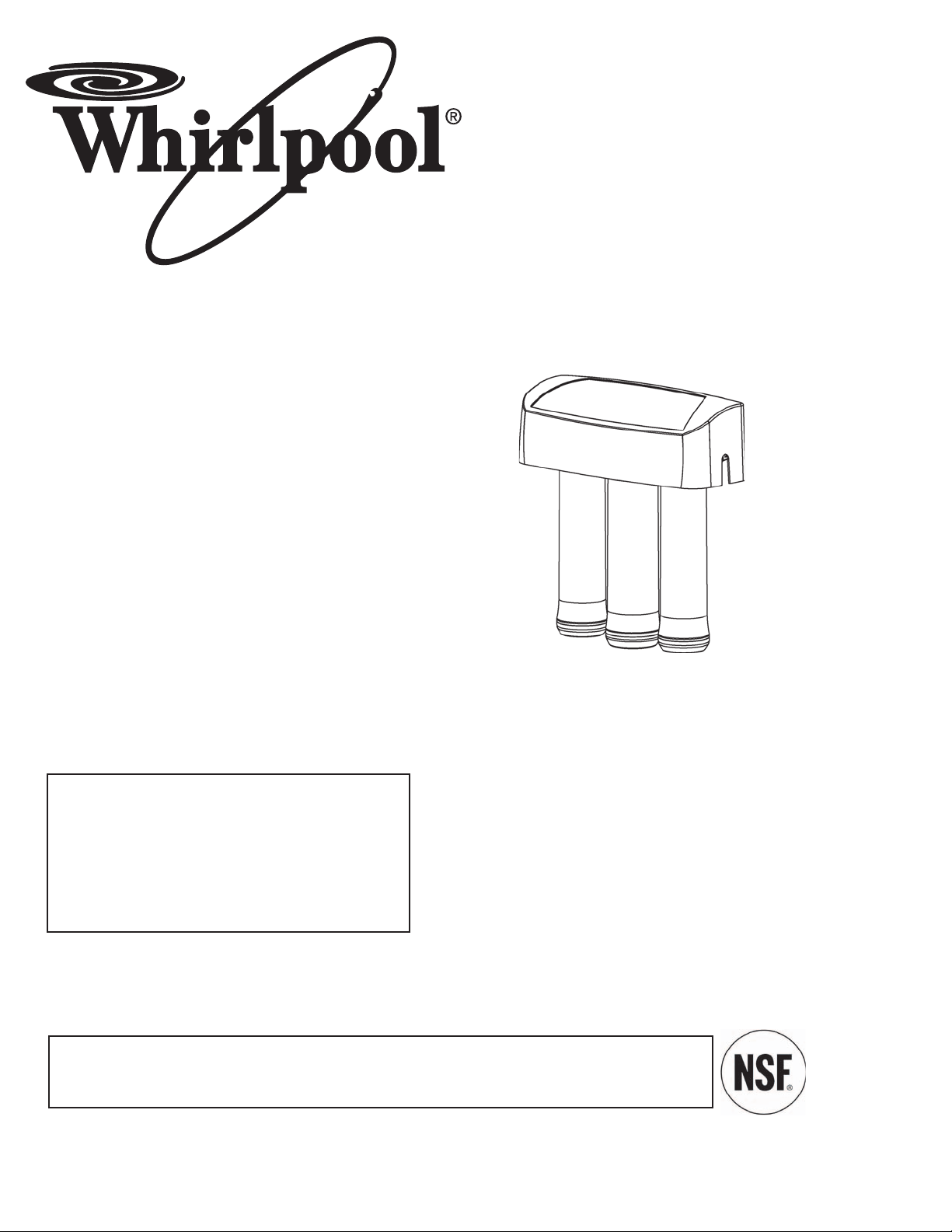
Whirlpool WHER25 User Manual
System tested and certified by NSF International
against NSF/ANSI Standard 42 and 58. See performance data sheet for details.
7272844 (Rev. K 9/24/07)
Product No. 8576162
Manufactured and warranted by
Ecodyne Water Systems, Inc.,
1890 Woodlane Drive
Woodbury, MN 55125
How to Install, operate and
maintain your Reverse Osmosis
Drinking Water System
Model WHER25
If you have any questions or concerns when
installing, operating or maintaining your
Reverse Osmosis System
call our toll free number:
1-866-986-3223
Monday- Friday, 8 AM-9PM EST
or visit www.ecodyne.org
Installation and Operation Manual

2
TABLE OF CONTENTS
Unpack and Check Shipment . . . . . . . . . . . . . . . . . . . . . . . . . . . . . . . . . . . . . . . . . . . . . . . . . . . . . . . . . . . . . . . . . . 3
Plan Your Installation . . . . . . . . . . . . . . . . . . . . . . . . . . . . . . . . . . . . . . . . . . . . . . . . . . . . . . . . . . . . . . . . . . . . . . 4-5
Overview and Site Preparation . . . . . . . . . . . . . . . . . . . . . . . . . . . . . . . . . . . . . . . . . . . . . . . . . . . . . . . . . . . . . . . . 6
Step 1-Install Supply Water Fitting . . . . . . . . . . . . . . . . . . . . . . . . . . . . . . . . . . . . . . . . . . . . . . . . . . . . . . . . . . . . . . 7
Step 2-Install Reverse Osmosis Drain . . . . . . . . . . . . . . . . . . . . . . . . . . . . . . . . . . . . . . . . . . . . . . . . . . . . . . . . . . 8-9
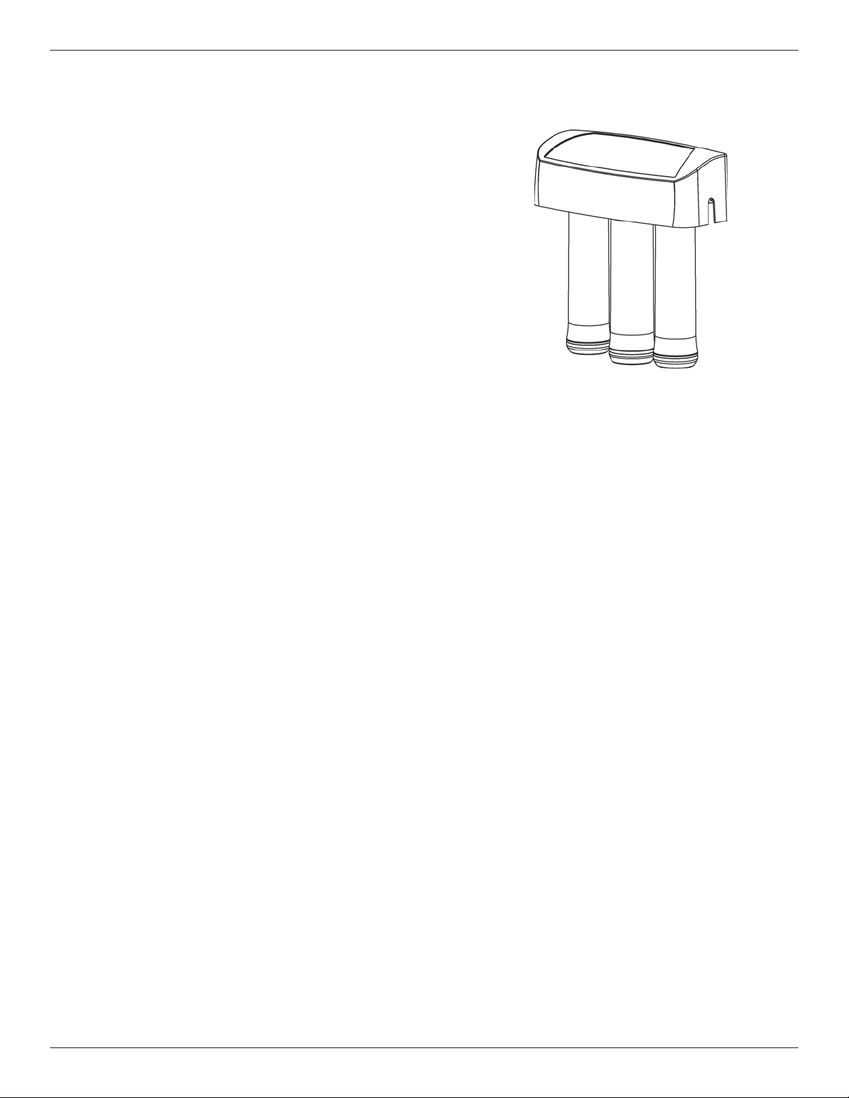
Step 3-Install Reverse Osmosis Filter Assembly . . . . . . . . . . . . . . . . . . . . . . . . . . . . . . . . . . . . . . . . . . . . . . . . . . 10
Step 4-Install Storage Tank . . . . . . . . . . . . . . . . . . . . . . . . . . . . . . . . . . . . . . . . . . . . . . . . . . . . . . . . . . . . . . . . . . . 11
Step 5-Install Reverse Osmosis Faucet . . . . . . . . . . . . . . . . . . . . . . . . . . . . . . . . . . . . . . . . . . . . . . . . . . . . . . . 12-13
Step 6-Connect Tubes . . . . . . . . . . . . . . . . . . . . . . . . . . . . . . . . . . . . . . . . . . . . . . . . . . . . . . . . . . . . . . . . . . . .14-15
Step 7-Sanitize, Pressure Test, Purge System . . . . . . . . . . . . . . . . . . . . . . . . . . . . . . . . . . . . . . . . . . . . . . . . . .16-17
How Your Reverse Osmosis Water System Works . . . . . . . . . . . . . . . . . . . . . . . . . . . . . . . . . . . . . . . . . . . . . .18-19
Maintenance . . . . . . . . . . . . . . . . . . . . . . . . . . . . . . . . . . . . . . . . . . . . . . . . . . . . . . . . . . . . . . . . . . . . . . . . . . . .20-21
Specifications . . . . . . . . . . . . . . . . . . . . . . . . . . . . . . . . . . . . . . . . . . . . . . . . . . . . . . . . . . . . . . . . . . . . . . . . . . . . . 22
Warranty Information . . . . . . . . . . . . . . . . . . . . . . . . . . . . . . . . . . . . . . . . . . . . . . . . . . . . . . . . . . . . . . . . . . . . . . . . 23
Troubleshooting . . . . . . . . . . . . . . . . . . . . . . . . . . . . . . . . . . . . . . . . . . . . . . . . . . . . . . . . . . . . . . . . . . . . . . . . . 24-25
Exploded View & Parts List . . . . . . . . . . . . . . . . . . . . . . . . . . . . . . . . . . . . . . . . . . . . . . . . . . . . . . . . . . . . . . . . 26-27
Questions?
Visit www.ecodyne.org
or call Toll Free
1-866-986-3223
Monday- Friday, 8 AM - 9PM EST
3
Packing List
Unpack and Check Your Carton
INSPECT SHIPMENT
Your Reverse Osmosis Drinking Water System is
shipped complete in one carton. Remove all items from
your shipping carton.
Check all items against the packing list below. Note any
items lost or damaged in shipment.
Note any damage to the shipping carton. Refer to the
exploded view and parts list in the back of the manual for
the part names and numbers of missing or damaged
items. If problems exist, refer to the website or the toll
free number listed throughout this manual.
Keep the small parts in the parts bag until you are ready
to install them.
NOTE: Codes in the state of Massachusetts require
installation by a licensed plumber and do not permit
the use of saddle valves.
If you live in the state of Massachusetts, review
plumbing code 248-CMR of the Commonwealth of
Massachusetts before proceeding with the installation.
Questions? Visit www.ecodyne.org or call Toll Free 1-866-986-3223
4
Plan Your Installation
FIG. 1
PLAN YOUR INSTALLATION
It is recommended to read through the entire manual
before beginning your installation. Follow all steps exactly.
Reading this manual will also help you get all the benefits
from your system.
Your Reverse Osmosis Drinking Water System can be
installed under a sink or in a remote location. Typical
remote sites are a laundry room or utility room. Review the
location options below and determine where you are going
to install your system.
NOTE: For best system performance, the feed water to
the system should be softened or less than 10 grains
per gallon hard.
UNDER THE SINK LOCATION
The Reverse Osmosis Filter Assembly and storage tank
are normally installed in a kitchen or bathroom sink cabinet. See Fig. 2.
A suitable drain point is needed for reject water from the
Reverse Osmosis filter.
REMOTE LOCATION
You can also locate the Reverse Osmosis Filter Assembly
and storage tank in a remote location away from the
Reverse Osmosis Faucet. You will need a nearby water
source and drain point.
See Fig. 3.
CHECK SPACE REQUIREMENTS
Check size and position of items for proper installation into
location chosen.
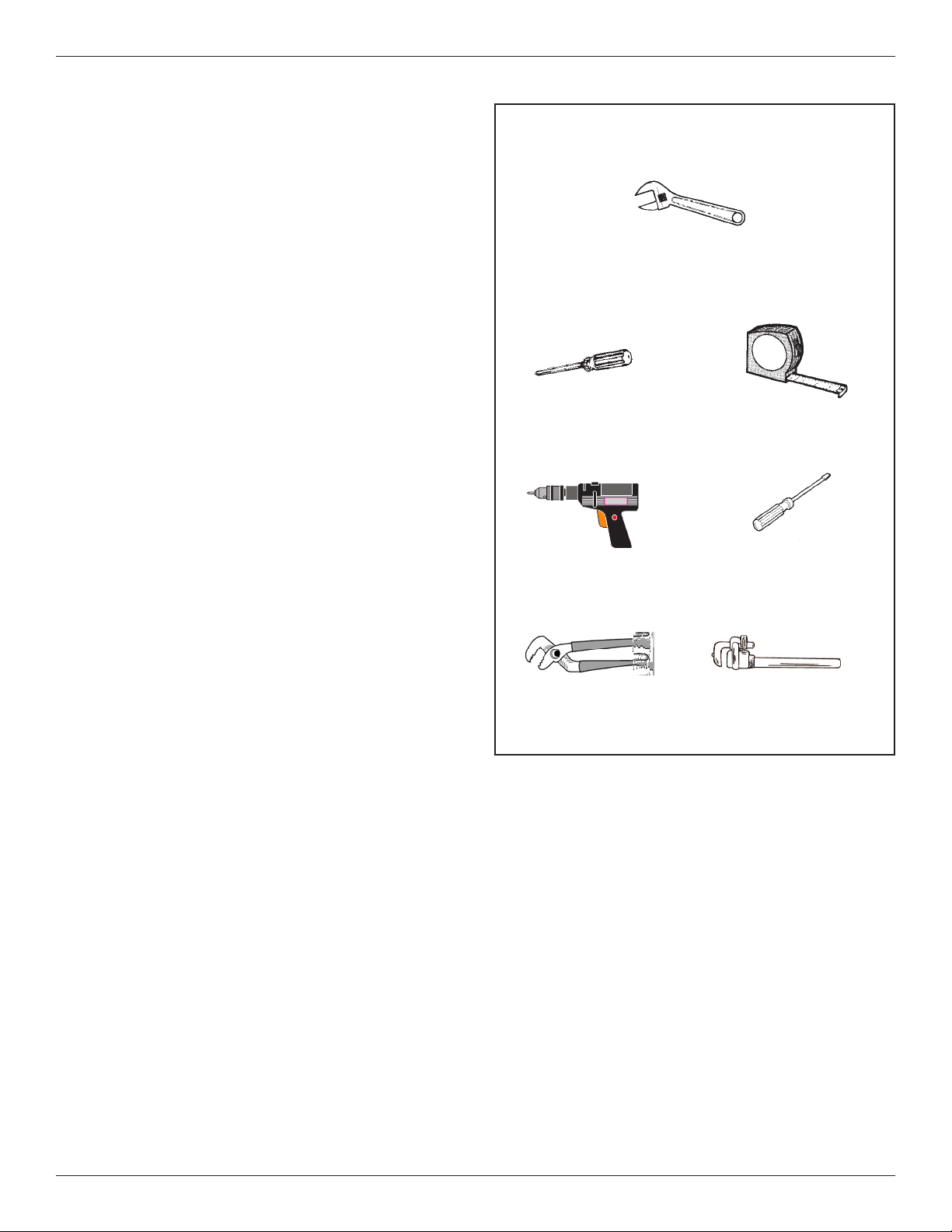
TOOLS NEEDED
Review the tools needed list. See Fig. 1. Gather needed
tools before proceeding with the installation. Read and follow the instructions provided with any tools listed here.
Questions? Visit www.ecodyne.org or call Toll Free 1-866-986-3223
TOOLS NEEDED
Adjustable wrench
Tape MeasurePhillips Screwdriver
Flathead Screwdriver
Drill & Drill bits, if required.
Large Adjustable Jaw Pliers or Pipe Wrench
5
6
Overview and Site Preparation
OVERVIEW
There are seven easy steps to installing your Drinking Water
system. They are as follows:
STEP 1 - Install Cold Water Supply fitting
STEP 2 - Install Drain Adapter
STEP 3 - Install Reverse Osmosis Assembly
STEP 4 - Install Storage Tank
STEP 5 - Install Reverse Osmosis Faucet
STEP 6 - Connect Tubing
STEP 7 - Sanitize, Pressure Test, Purge System
These steps are explained in detail over the next few pages.
It is recommended to read through the entire manual before
beginning your installation. Follow all steps exactly. Reading
this manual will also help you receive and use all the benefits your Reverse Osmosis System can give you.
PREPARE SITE FOR INSTALLATION
1. Before starting, close the hot and cold water shutoff
valves (See Figure 5).
2. Temporarily place tank and filter assembly into cabinet.
Double check position of items and space required for
proper installation.
3. Remove tank and filter from cabinet and set aside.
NOTE: You must check and comply with all local plumbing codes.
NOTE: Codes in the state of Massachusetts require
installation by a licensed plumber and do not permit the
use of saddle valves.
If you live in the state of Massachusetts, review plumbing code 248-CMR of the Commonwealth of
Massachusetts before proceeding with the installation.
FIG. 4
Questions? Visit www.ecodyne.org or call Toll Free 1-866-986-3223
7
Step 1 - Install Supply Water Fitting
Questions? Visit www.ecodyne.org or call Toll Free 1-866-986-3223
FIG. 5
Saddle Valve Connection
(Included in package)
Clamp Z
Nut
Nut - tighten
if necessary
Insert
Ferrule
(Plastic)
Use to Connect
Tubing
Handle
Valve
Clamp X
Seal
CHOOSE TYPE OF WATER FITTING TO INSTALL
Locate the cold water line in the sink cabinet. It is recommended, but not required, that the cold water line be soft
water. You can use the saddle valve provided with your unit
to tap into the cold water line. See Fig. 5. Or you can purchase standard pipe fittings locally such as a compression
fitting. The fitting must provide a leak-tight connection to the
Reverse Osmosis 1/4" tube.
NOTE: Local code may dictate which type of water fitting is used. Consult a plumber if you are not familiar
with local codes or plumbing procedures.
NOTE: Codes in the state of Massachusetts require
installation by a licensed plumber and do not permit the
use of saddle valves.
If you live in the state of Massachusetts, review plumbing code 248-CMR of the Commonwealth of
Massachusetts before proceeding with the installation.
INSTALL SADDLE VALVE
(Included with your package)
This fitting will be installed on the cold water pipe. The fitting
must provide a leak-tight connection to the Reverse
Osmosis 1/4" tubing.
Complete the following steps to install the saddle valve
assembly.
1. Review Fig. 5 and familiarize yourself with all parts of the
saddle valve. This valve will self-tap a hole in copper tubing or plastic pipe.
IMPORTANT: Before starting, close the hot and cold
water shutoff valves (See Figure 5).
2. If installing on iron pipe, drill a 1/8” hole for the piercing
pin.
IMPORTANT: If a battery-powered hand drill is not
available and an electric drill is used, ensure that the
drill is properly grounded.
3. Place the seal on the inside of Clamp X. See Fig. 5. Turn
the valve handle all the way out.(counter-clockwise) Be
sure the piercing pin does not stick out beyond the seal.
4. Place Clamp X and Z around the pipe. Secure in place
with two screws. Tighten both screws evenly. Do not over
tighten screws. See Fig. 5.
5. Turn the valve handle all the way in. (clockwise) This will
pierce the wall of the pipe. See Fig. 5.
6. Do not
connect the tubing to the fitting at this time. This
will occur later in the installation.
NOTE: Once the saddle valve is installed, the nut near
the handle may need to be tightened to prevent possible leaks.
Pre-Drill
1/8'' Hole
(Iron Pipe)
Cold Water
Shutoff Valve
Hot Water
Shutoff Valve
8
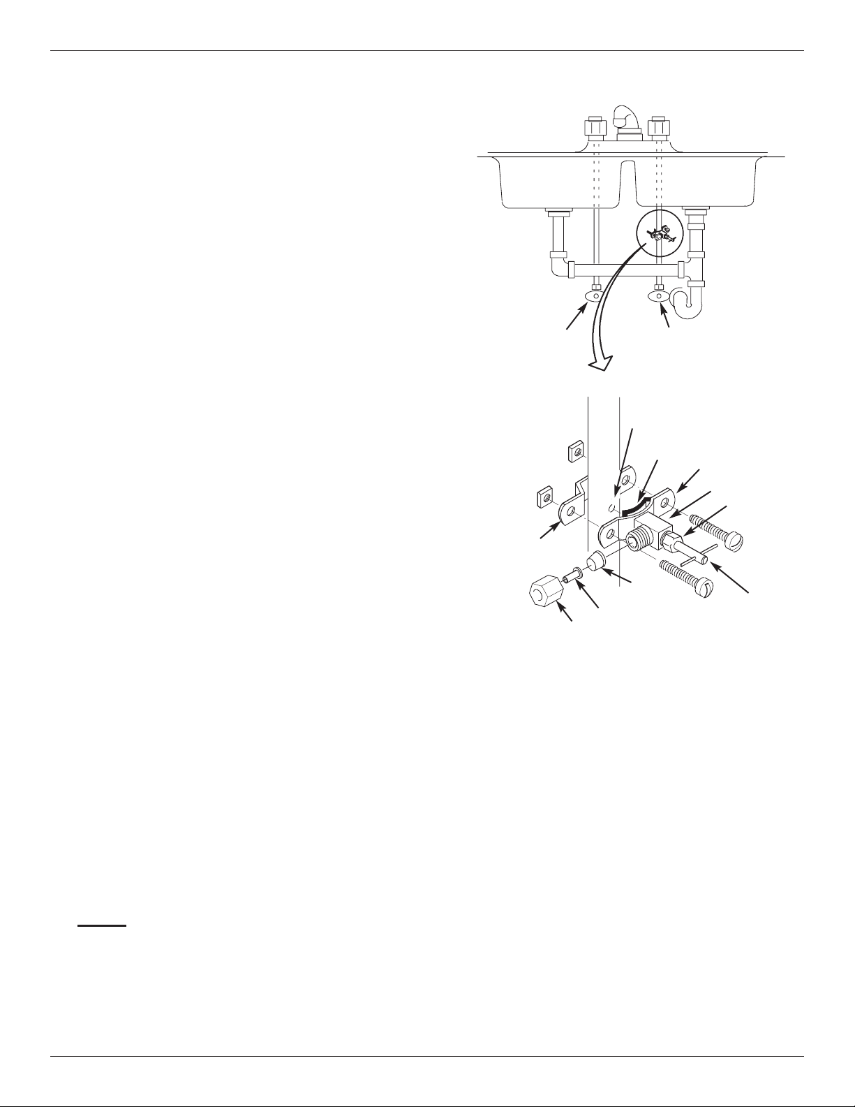
Step 2 - Install RO Drain Under Sink
FIG. 6
FIG. 7
FIG. 8
INTRODUCTION
A suitable drain point is needed for the reject water from
the Reverse Osmosis Filter. You have two options to
choose from:
• Install the Drain Adapter included with your unit
See Fig 6, Fig. 7, and Fig. 8. This is used in under the
sink installations. The drain adapter kit is installed onto
your sink drain pipe above the P-trap. See Fig. 6.
• Use another existing drain in your home
(See Fig 9, Fig. 10) This is usually used in remote
location type installations. The drain tube from the
Reverse Osmosis Filter runs directly to an open drain.
See Fig. 9 & 10.
NOTE: Local code may dictate which type of drain
installation is used. Other than local code, either
drain install type may be used in both under the sink
or remote location installations. Consult a plumber if
you are not familiar with plumbing procedures.
INSTALL DRAIN ADAPTER KIT
(Under sink Installation)
In an under the sink installation, you normally use the
(P-trap) drain adapter. A drain adapter kit is included in
your package. Review the drain adapter kit parts in Fig. 7.
The drain adapter is always installed in the sink drain
pipe, above or ahead of the P- trap. See Fig. 6 & 8. Be
sure to comply with your local plumbing codes. The drain
adapter fits 1-1/2" sink drain pipes. Other drain pipe fittings, purchased locally, may be needed in addition to the
adapter.
1. Slowly disassemble the sink drain pipe between the
sink P-trap and the sink tailpiece. See Fig. 6 & 8.
2. Clean the sink tailpiece to assure a leak-tight fit.
3. Install drain adapter directly onto the sink tailpiece
using the ferrule and nut. Snug the nut, but do not
tighten. See Fig. 7.
4. Assemble the drain tubing connector to the drain
adapter using the ferrule and nut. Snug the nut, but do
not tighten. See Fig. 7.
NOTE: Locate so drain tubing from the Reverse
Osmosis faucet will make a straight run to the
adapter, without dips, loops, low spots or kinks.
See Fig. 8.
5. Turn the connector to about 45° (10:00 or 2:00 position). See Fig. 7. Tighten the nut securely.
6. Assemble the P-trap to the drain adapter, and other
drain pipe fittings as required to complete the drain
run. See Fig. 6.
Note: If needed, you can cut the unthreaded end of
the adapter to make it fit. Do not cut too short or
the adapter will not make a leak-tight seal with the
connecting fitting.
7. Tighten all connections, but do not over tighten plastic
connections.
Drain
Adapter
P–Trap
P–Trap
Sink Tailpiece
Drain Adapter
Drain Tubing
Connector
Cut, if
needed.
45°
45°
2:00
10:00
Ferrule
Single trap
Double Trap
Nut
Nut
Ferrule
Under The Sink Installation
IMPORTANT: Locate drain adapter so when the black drain tube
from the Reverse Osmosis Faucet is installed later
on, it will make a straight run to the adapter, without dips, loops, low spots or kinks
P-Trap
HOT
COLD
Drain Adapter
Black Drain
Tube
9
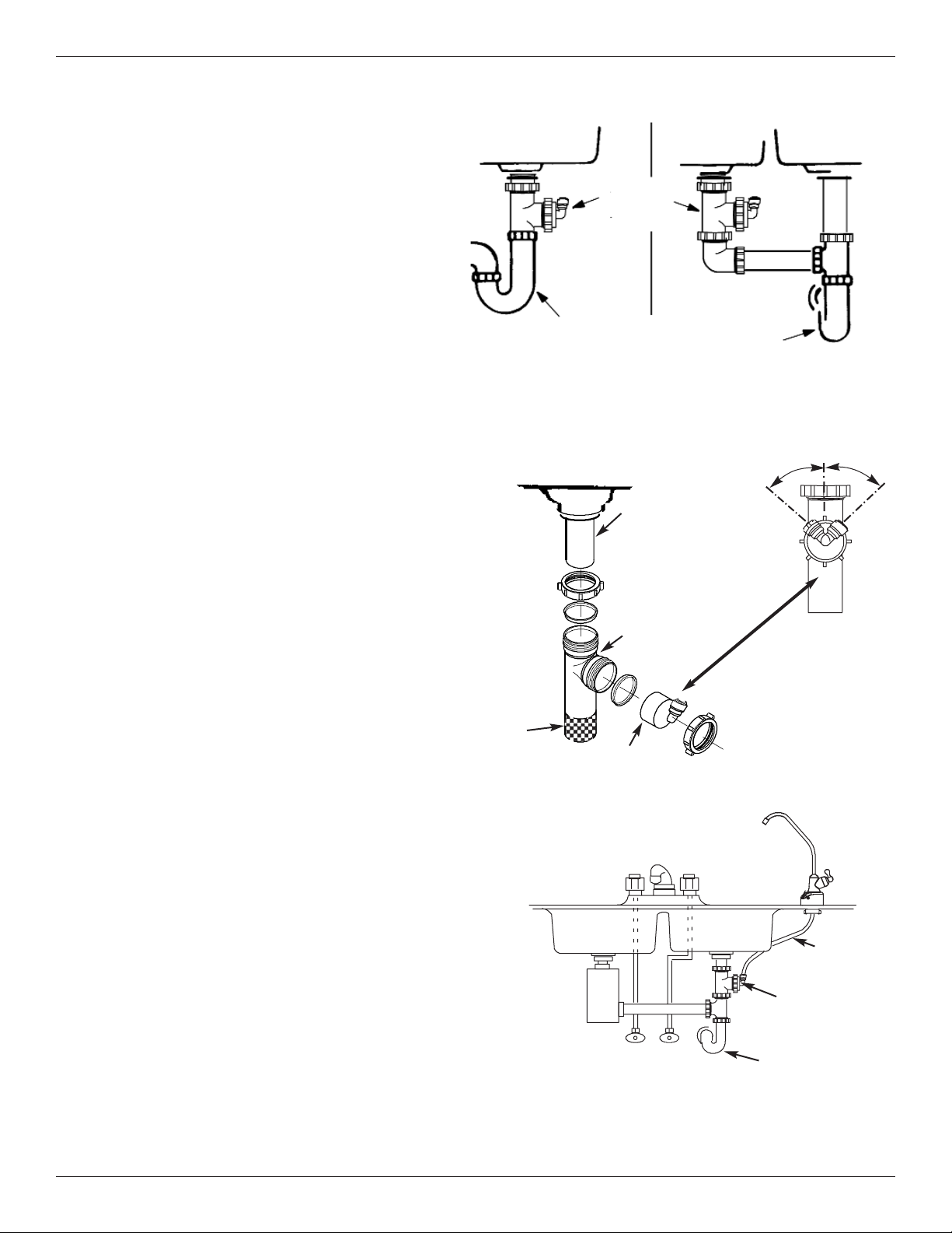
Step 2 - Install RO Drain In Remote Location
FIG. 10
FIG. 9
INSTALL A REMOTE DRAIN POINT
AND AIR GAP (Remote Location)
You can also run the drain tubing to an existing drain in
the house. A floor drain, laundry tub, standpipe, sump,
etc. are suitable drain points. See Fig. 10. This type of
drain is the preferred over the p- trap drain adapter.
Check your local codes. Longer lengths of tubing (see
parts list in back of manual) may be needed.
Always be sure to provide an air gap between the end of
the hose and the drain point. This will prevent water from
backing up into the system. Airgaps are required code in
most areas.
To install a remote drain point, complete the
following steps:
1. Locate the 1/4” red tubing on the Reverse Osmosis
filter assembly. See Fig. 9.
2. Determine if this length is long enough to reach the
drain point.
3. If not, disconnect the 1/4” red tubing and replace with
an adequate length of tubing to reach the drain point.
Refer to Step 5 later in the manual on how to disconnect and connect tubing.
Note: A flow control insert is located in the red
tube. Refer to Fig 27. This insert must be saved
and placed in the new length of tubing.
4. Run the tubing to the drain point and secure at the
end with a bracket (purchased locally). See Fig. 10.
Provide a 1-1/2” air gap between the end of the tube
and the drain. See Fig. 10.
Outside Faucet
(Hard Water)
Soft, Cold Water
Soft, Hot
Water
Outside Faucet
(Hard Water)
Floor
Drain
Water
Softener
Hard
Water
to House
RED
Tubing to
Drain
Main
Shutoff
Valve
Storage
Ta nk
YELLOW
Tubing to
Tank Storage
Water Meter
Reverse
Osmosis
System
GREEN Tubing
to Reverse
Osmosis
System
BLUE
Tubing to
Reverse
Osmosis
Faucet
Stand pipe
Airgap
1-1/2”
Sump
Airgap
1-1/2”
A
irgap
1-1/2
”
Airgap
1-1/2”
Laundry Tub
Water Heater
Shut-off
Valve
Reverse
Osmosis
Drain
Hard Water Line
1/4'' RED Tubing
Remote Location
Installation
Soft water
to Reverse
Osmosis
System
 Loading...