


Model WHER12
Model WriER18
How to install, operate and
TM
maintain your Reverse Osmosis
Drinking Water System
Do not return R.O. to store
If you have questions or concerns when
installing, operating or maintaining your
R.O. call our toll free number:
1-866-986-3223
Monday - Friday, 8 am - 9 pm EST
System tested and certified by NSF International
against NSF/ANSl Standard 58.
See performance data sheet for details,
7263942 (Rev. D 8/18/04)
Product No. 8562920
Table of Contents
Before You Start ...................................................................... 3
Inspect Shipment ..................................................................... 4
Reverse Osmosis Information .......................................................... 5
How the RO System Works ............................................................ 5
Prefilter ........................................................................... 5
Reverse Osmosis (RO) Cartridge .................................................... 5
Storage Tank ..................................................................... 5
Post Filter ........................................................................ 5
Faucet ........................................................................... 5
Faucet Electronics ................................................................. 6
Shutoff Assembly .................................................................. 6
Check Valve ...................................................................... 6
Flow Control ...................................................................... 6
Reverse Osmosis Dimensions .......................................................... 7
Plan the Installation ................................................................... 7
Tools and Materials Needed ........................................................ 7
Location Requirements ............................................................. 7
Remote Locations ................................................................. 7
Air Gap Requirements .............................................................. 8
Installation ........................................................................... 9
Install Cold Water Supply Fitting ..................................................... 9
Install Drain Adaptor .............................................................. 10
Install Faucet .................................................................... 11
Install RO Assembly .............................................................. 13
Install Storage Tank, Make Remaining Tubing Connections ............................ 13
Sanitize, Pressure Test & Purge .................................................... 14
Routine Maintenance ................................................................. 16
Prefitter and Post Filter Cartridges .................................................. 16
RO Membrane Cartridge .......................................................... 17
Flow Control ..................................................................... 18
Tubing Connection ............................................................... 18
Automatic Shutoff ................................................................ 19
Troubleshooting Guide ............................................................... 20
Specifications ....................................................................... 21
Repair Parts ......................................................................... 22
Product Schematic ................................................................... 24
Warranty ............................................................................ 24

Before You Start
For installations in the Commonwealth of Massachusetts:
Installation by a licensed plumber is required. Plumbing code 248-CMR of the Commonwealth
of Massachusetts must be used for installation.
Read all steps and guides carefully before installing and using your reverse osmosis system. Follow
all steps exactly to correctly install. Reading this manual will also help you to get all the benefits from
the reverse osmosis system.
Do not attempt to use this product to make sate drinking water from non-potable water sources. Do
not use the system on microbioh)gically unsafc water, or water of unknown quality without adequate
disinfection before or after the system. This system is certified for cyst reduction and may be used on
disinfected water that may contain filterable cysts.
Some or all of the contaminants listed may not be in your water supply.
All plumbing should be done in accordance with local codes and requirements.
This system shall only be used for arsenic reduction on chlorinated water supplies containing detect-
able residual tree chlorine at the system inlet. Water systems using an inline chlorinator should provide
a one minute chlorine contact time betk)re the Re system. Conforms to NSF/ANSI 58 for pentavalent
arsenic reduction. See performance data sheet and Arsenic Facts section tk_ran explanation of reduc-
tion performance.
This system is acceptable for treatment of influent concentrations of no more than 27 mg/L nitrate and
3 mg/L nitrite in combination measured as N and is certifed tk_rnitrate/nitrite reduction only tk_rwater
supplies with a pressure of 280 kPa (40 psig) or greater. This system is supplied with a nitrate/nitrite
test kit. Product water should be monitored periodically according to the instructions provided with
the test kit.
The reverse osmosis system works on water pressures of 40 psi (minimum) to 100 psi (maximum). If
you have questions about your water pressure, contact a licensed plumber.
For indoor use only. Certification claims are tk)rtemperatures of the water supply to the reverse osmosis
system of 40°F to 100°K Install on the cold water line.
To see if your water is within the required specifications, read the water specifications to be sure your
water supply is within these limits. TDS test kits are available by calling 1-800-826-8553 ext. 47, or
check the water testing section of your local phone directory.
The reverse osmosis membrane may contain a preservative tk_rstorage and shipment. Be sure to purge
betk_re using product water. See "Sanitize, Pressure Test and Purge" section.
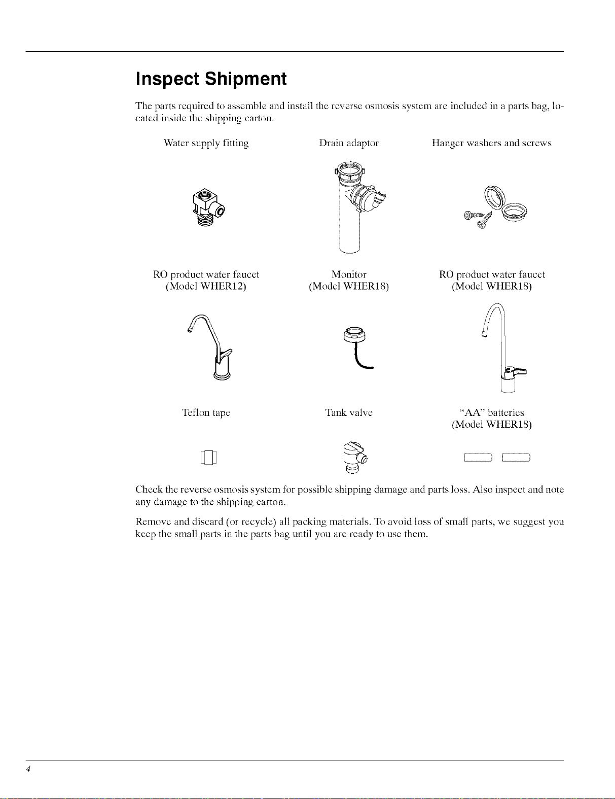
Inspect Shipment
The parts required to assemble and install the reverse osmosis system are included in a parts bag, lo-
cated inside the shipping carton.
Water supply fitting
RO product water faucet
(Model WriER12)
Teflon tape Tank valve
Drain adaptor
Monitor
(Model WHERI 8)
Hanger washers and screws
RO product water faucet
(Model WriER 18)
"AA" batteries
(Model WriER 18)
KZZZ3 KZZZ3
Check the reverse osmosis system tk)r possible shipping damage and parts loss. Also inspect and note
any damage to the shipping carton.
Remove and discard (or recycle) all packing materials. To avoid loss of small parts, we suggest you
keep the small parts in the parts bag until you are ready to use them.
Reverse Osmosis Information
The Reverse Osmosis (RO) Drinking Water System is a water treatment unit. It uses household water
pressure to reverse a natural physical process called osmosis. Water, under pressure, is forced through
a semi-permeable membrane where minerals and impurities are filtered out. Clean drinking water goes
to the faucet or storage tank, while minerals and impurities are sent to the drain with Re waste water.
The minerals and impurities are measured in water as total dissolved solids (TDS).
The reverse osmosis system includes replaceable pre and postfilter sediment-carbon cartridges. The
prefilter removes sand, silt, dirt, rust particles, other sediments, and chlorine from the water supply be-
fore it can enter the Re membrane. The postfilter removes any tastes and/or odors that may remain
in the water, after passing through the Re membrane, before going to the Re faucet. To prevent water
waste, an automatic shutoff valve closes when the Re faucet is closed and the storage tank is full.
The reverse osmosis system gives a continuous supply of sparkling clear, delicious water ff_rdrinking,
cooking and other uses. The reverse osmosis process makes water very slowly, that is why there is a
2.3 gallon* storage tank. This will enable you to have high quality R.O. product water tk)ryour cooking
and drinking water needs.
* Exact storage capacity depends on water pressure.
How a Reverse Osmosis System Works
Prefilter
Water fronl the cold water supply pipe enters the Re assembly prefilter first. The prefilter has a re-
placeable sediment cartridge with activated carbon in its composition. The cartridge removes sand, silt,
dirt, other sediments, and up to the ppm of chlorine shown in the specifications from the feed water.
See "Product Specifications" section. Chlorine can adversely effect the Re membrane lifc. Filtered,
clean, chlorine-free water flows from the prefilter, to the Re membrane cartridge.
Reverse Osmosis (RO) Cartridge
The Re cartridge is a tightly wound special membrane. The membrane removes the dissolved solids
and organic matter when water is forced through the cartridge. High quality product water exits the
Re cartridge and goes to the storage tank, or to the postfilter and Re faucet. Reject water, with the
dissolved solids and organic matter, is routed through the flow control and to the drain.
Storage Tank
The storage tank holds up to 2.3 gallons of product water. The higher the incoming water pressure, the
more water will be stored in the tank, up to 2.3 gallons. A diaphragm inside the tank keeps water pres-
surized to about 30 psi, when the tank is full, to provide fast flow to the Re faucet. The dry side of the
diaphram that divides the tank is pressurized with air to 5 - 7 psi.
Post Filter
After leaving the storage tank, but before going to the Re faucet, product water goes through the post
filter. The post filter is an activated carbon type filter. Any remaining tastes and odors are removed
from the product water. Taste-free, odor-free, clean, high quality drinking water is available for use.
Faucet
The sink or countertop faucet has a hand operated lever or knob to access drinking water. To comply
with plumbing codes, an air-gap is built into the faucet drain water connection.
Faucet Electronics
If so equipped, the Re system will monitor the total product flow of the reverse osmosis system and
also length of time the filters have been installed. The faucet base has an indicator light that flashes
to inform you of the status of the Re membrane and filters. This indicator light will flash only when
water is flowing.
• Green - Re membrane and filters are good.
• Amber - Warning, pre and post filters will need replacing shortly. Filters need replacing, when
water has been drawn, after 182 days (or 750 gallons have been used).
• Red - Re membrane needs to be replaced.
When the two "AA" batteries are first applied at initial start up, the LED indicator light will flash in
a red, amber, green sequence. All timers and counters are reset to zero.
In order to reset the monitor time and gallon count feature, the batteries should be removed for a mini-
mum of five seconds and then reinserted.
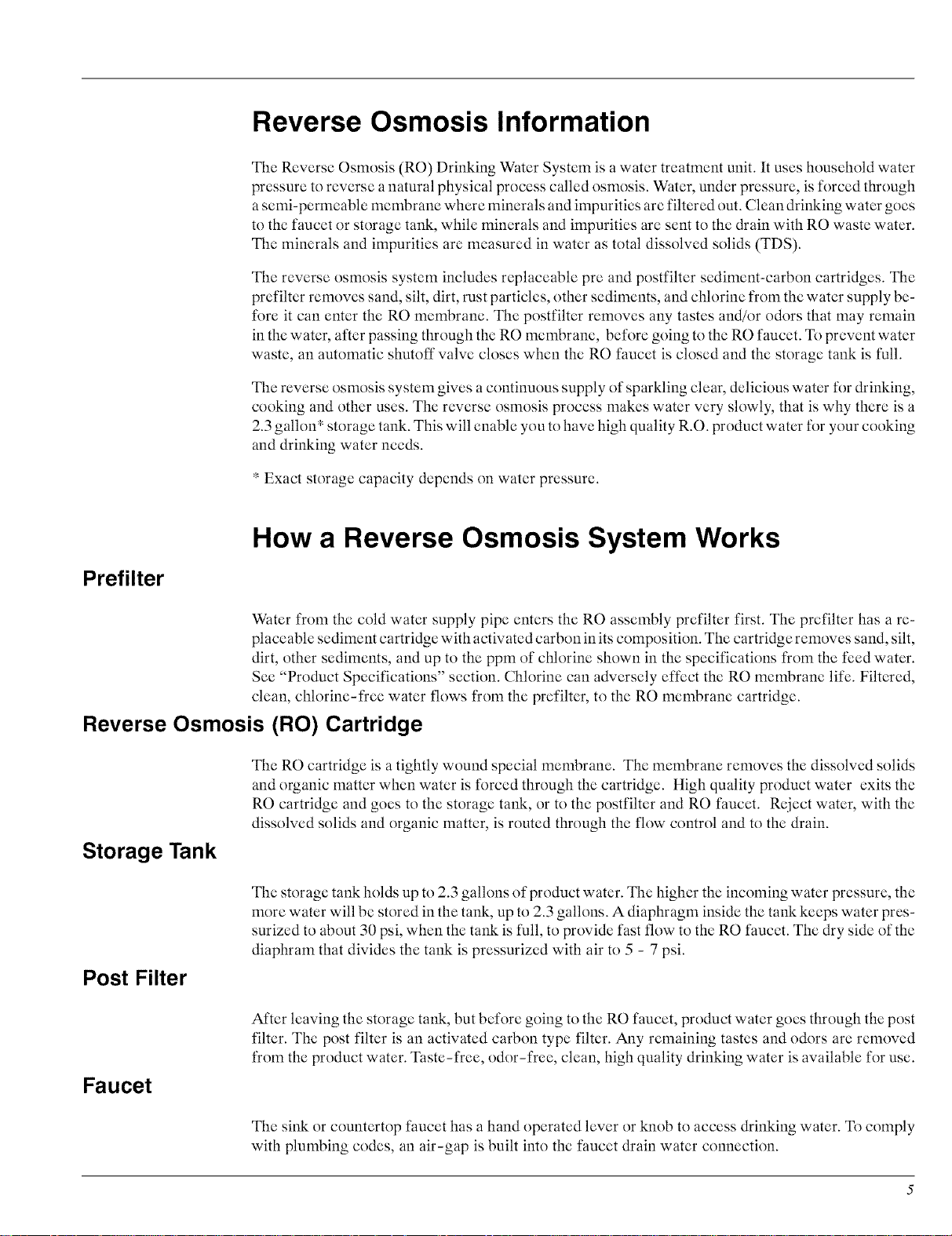
Batteries need to be replaced once a year at the time of filter replacement. Do not mix battery types,
use only "AA" alkaline batteries. Improper placement of batteries could damage electronics. Use care
when inserting batteries to align them correctly in manifold with the proper polarity.
Electronics
(monitored
models only)
Shutoff Assembly
Check Valve
Flow Control
Batteries
Automatic
Shut Off
Figure 1
To conserve water, the drinking water system has an automatic shutoff system. When the storage tank
has filled to capacity, and the drinking water faucet is closed, pressure closes the shutoff to stop flow
to drain. Pressure in the storage tank is about halt" of the water supply pressure. After drinking water
is used, and pressure in the system drops, the shutoff opens to allow water flow again.
A check valve (Figure 13) is located in the Re manifold, above the center sump. The check valve pre-
vents a backward flow of product water from the storage tank. A backward flow could damage the Re
membrane.
Water flow through the Re membrane is regulated by the flow control. It maintains the desired flow
rate to obtain the highest quality drinking water. The flow control is located in the end of the 1/4" red
drain tubing, at the Re manifold drain port.
(monitored
models only)

Reverse Osmosis Dimensions
T
Plan the Installation
Tools and Parts Needed
Assemble the required tools be*k_restarting installation. Read and follow the instructions providedwith
any tools listed here.
• Adjustable wrench
• Larger adjustable jaw pliers
• Screwdrivers
• Electric drill and drill bit
Location Requirements
Consider all of the following when selecting an installation location for the reverse osmosis.
• For optimum performance your reverse osmosis system should be installed on softened water.
15"
T
13"
• Pliers
• Pipe wrench
• Plumbers putty (for sink, if necessary)
Remote Locations
• To provide supply water to the RO system inlet use the feed supply fitting (provided) or buy and
install pipe fittings for tubing connection. See "Install Cold Water Supply Fitting" section.
• A refrigerator ice maker may not operate properly when connected to a reverse osmosis system
that has been installed on a water system that operates outside of the specified pressures listed. See
"Product Specifications" section.
• Chlorine in the water can adversely effcct the RO membrane life. Most cities add chlorine to the
water supply to kill bacteria. The prefilter removes chlorine up to the limits shown in the specifica-
tions before it enters the RO membrane. It is important to replace the prefilter cartridge at least
every 6 months. See "Product Specifications" section.
• Check your water supply. The cold water supply to the RO system must be within certain quality
limits. See "Product Specifications" section. If supply water is not within limits, the RO system
can not make product water as it should and reduced RO membrane life will result.
• A basement area underneath the sink
Parts needed for remote location:
• Longer lengths of tubing, see "Repair Parts" section
• Telephone style wire extension (purchase separtately) may be needed
IMPORTANT: Telephone style wire extension must consist of a male connector on one end and
a female connector on the other to keep proper polarity. Polarity may be reversed
if a coupler is used and the monitor will not work.
• An adjacent room or closet

The RO assembly and storage tank is designed for installation under the sink, usually in the kitchen
or bathroom. The RO assembly mounts on a wall surface, or can lay on the cabinet floor next to the
storage tank. Hanger washers and wood screws are included fk)r cabinet wall mounting. The RO prod-
uct water faucet installs on the sink, or on the countertop next to the sink.
NOTE:
Tubing lengths allow for the removal of the assembly from the hanger washers for
servicing. If tubing lengths are shortened for heater appearance, it may be necessary
to keep the assembly on the hanger washers tk)r service.
RO product
water faucet _ ]1
(Model WriER12) ..___
HOT 'COLi/
/
/
/
sink drain
p-trap
RO Assembly
RO product
water faucet
(Model WriER18)
drain adaptor
Figure 2
Air Gap Requirements
A suitable drain point is needed for reject water from the RO membrane. A floor drain, laundry tub,
standpipe, sump, etc., is preferred. Asink p-trap drain adaptor is included to install where codes permit,
as an optional drain point. See "Install Drain Adaptor" section.
171/2" [
argap
/
floor drain
Z/2"
I airgap
-Z Cr--
standpipe
airgap
sump
f
/
171/2" __ _
argap /j
laundry tub
 Loading...