

Whirlpool WET4027HW0, WET4027EW1 Installation Guide

24" (61 cm) & 27" (69 cm) Electric Washer/Dryer
Installation Instructions
Instructions pour l’installation de la laveuse/sécheuse
électrique de 24" (61 cm) et 27" (69 cm)
Instrucciones de instalación de la lavadora/secadora
eléctrica de 24" (61 cm) y 27" (69 cm)
Table of Contents Table des matières
WASHER/DRYER SAFETY ..........................................................2
INSTALLATION REQUIREMENTS ............................................... 4
Tools and Parts ..................................................................... 4
LOCATION REQUIREMENTS ......................................................6
DIMENSIONS/CLEARANCES ..................................................... 7
DRAIN SYSTEM ........................................................................... 9
ELECTRICAL REQUIREMENTS – U.S.A...................................10
ELECTRICAL REQUIREMENTS – CANADA ............................. 11
REMOVE SHIPPING STRAP ...................................................... 12
INSTALL LEVELING LEGS .........................................................13
REMOVE FOAM PACKING (24" models) ..................................13
ELECTRICAL CONNECTION (U.S.A. ONLY) ............................ 14
VENTING ..................................................................................... 26
Venting Requirements ........................................................ 26
Plan Vent System ................................................................ 27
Install Vent System ............................................................. 28
CONNECT DRAIN HOSE ........................................................... 29
CONNECT INLET HOSES .......................................................... 30
CONNECT VENT ........................................................................ 31
LEVEL WASHER/DRYER ........................................................... 32
COMPLETE INSTALLATION CHECKLIST ................................ 33
SÉCURITÉ DE LA LAVEUSE/SÉCHEUSE ................................34
EXIGENCES D’INSTALLATION .................................................36
Outillage et pièces .............................................................36
EXIGENCES D’EMPLACEMENT .............................................. 38
DIMENSIONS/DISTANCES DE DÉGAGEMENT ....................... 39
SYSTÈME DE VIDANGE ............................................................ 41
SPÉCIFICATIONS ÉLECTRIQUES – CANADA .........................42
ENLEVER LA SANGLE D’EXPÉDITION .................................... 43
INSTALLATION DES PIEDS DE NIVELLEMENT ......................44
ENLEVER L’EMBALLAGE EN MOUSSE (modèles de 24") ..... 44
ÉVACUATION .............................................................................45
Exigences concernant l’évacuation .................................45
Planication du système d’évacuation ............................46
Installation du conduit d’évacuation ................................ 47
RACCORDEMENT DU TUYAU DE VIDANGE ........................... 48
RACCORDEMENT DES TUYAUX D’ARRIVÉE D’EAU ............. 49
RACCORDEMENT DU CONDUIT D’ÉVACUATION .................50
ÉTABLISSEMENT DE L’APLOMB
DE LA LAVEUSE/SÉCHEUSE ....................................................51
LISTE DE VÉRIFICATION POUR L’ACHÈVEMENT
DE L’INSTALLATION .................................................................. 52
Índice
SEGURIDAD DE LA LAVADORA/SECADORA ......................... 54
REQUISITOS DE INSTALACIÓN ............................................... 56
Herramientas y piezas ....................................................... 56
REQUISITOS DE UBICACIÓN ................................................... 58
DIMENSIONES Y ESPACIOS LIBRES....................................... 59
SISTEMA DE DESAGÜE ............................................................ 61
REQUISITOS ELÉCTRICOS ...................................................... 62
QUITE EL FLEJE DE EMBALAJE .............................................. 64
INSTALACIÓN DE LAS PATAS NIVELADORAS........................65
QUITE EL EMBALAJE DE HULE
ESPUMA (modelos de 24") ....................................................... 65
INSTALLATION NOTES
Date of purchase: _________________________________________
Date of installation: _______________________________________
Installer: _________________________________________________
Model number: ___________________________________________
Serial number: ____________________________________________
NOTAS DE INSTALACIÓN
Fecha de la compra: ______________________________________
Fecha de la instalación: ___________________________________
Instalador: _______________________________________________
Número de modelo: _______________________________________
Número de serie: _________________________________________
W10894254B
CONEXIÓN ELÉCTRICA ............................................................ 66
VENTILACIÓN ............................................................................ 78
Requisitos de ventilación ..................................................78
Planicación del sistema de ventilación .......................... 79
Instalación del sistema de ventilación ............................. 80
CONECTE LA MANGUERA DE DESAGÜE ............................... 81
CONECTE LAS MANGUERAS DE ENTRADA .......................... 82
CONECTE EL DUCTO DE ESCAPE .......................................... 83
NIVELACIÓN DE LA LAVADORA/SECADORA ......................... 84
LISTA DE CONTROL PARA LA REALIZACIÓN
DE LA INSTALACIÓN .................................................................85
NOTES CONCERNANT L’INSTALLATION
Date d’achat : ____________________________________________
Date d’installation : _______________________________________
Installateur : ______________________________________________
Numéro de modèle : ______________________________________
Numéro de série : _________________________________________
Washer/Dryer Safety
2
3
Installation Requirements
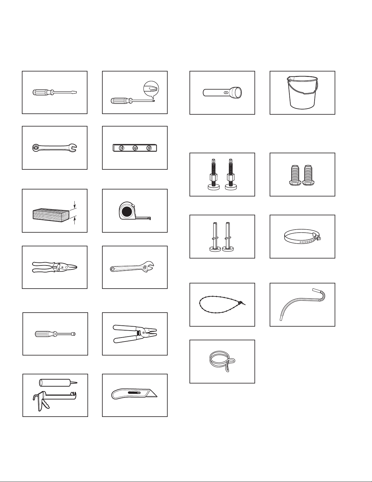
Tools and Parts
Gather required tools and parts before starting installation.
Tools needed:
Flat-blade screwdriver #2 Phillips screwdriver
Adjustable or open-end
wrench 9/16" (14 mm)
4" min
(102 mm)
Wood block
Level
Ruler or measuring tape
Optional tools:
Flashlight Bucket
Parts supplied:
NOTE: Remove parts package from the washer basket.
Check that all parts were included.
Front leveling feet with
nuts (2) (27" models)
Front leveling legs (2)
(24" models)
Tin snips (new vent
installations)
1/4" nut driver
(recommended)
Caulking gun and compound
(new vent installations)
Adjustable wrench that
opens to 1" (25 mm) or
hex-head socket wrench
Wire stripper
Utility knife
Rear leveling legs (2)
(24" models)
Plastic strap (24" models)
Silver double-wire hose clamp
Shipping strap (27" models)
(Not in parts bag. See
“Remove Shipping Strap.”)
Drain hose
4

Parts needed: (Not supplied with washer/dryer)
n
Vent clamps
n
Vent elbows and ductwork
Inlet hoses with
flat washers
Check local codes, electrical supply and venting, and read
“Electrical Requirements” and “Venting Requirements” before
purchasing parts. Mobile home installations require metal
exhaust system hardware available for purchase from the
dealer from whom you purchased your washer/dryer. For
further information, please reference the “Assistance or
Service” section of the Washer/Dryer Use and Care Guide.
Optional equipment: (Not supplied with washer/dryer)
Refer to your Use and Care Guide for information about
accessories available for your washer/dryer.
Alternate parts: (Not supplied with washer/dryer)
Your installation may require additional parts. To order, please
refer to toll-free numbers on back page of your Use and Care
Guide.
If you have: You will need:
Overhead sewer Standard 20 gal. (76 L) 39" (991 mm)
tall Drain Tub or Utility Sink, Sump
Pump and Connectors (available from
local plumbing suppliers)
Floor drain Siphon Break Part Number 285320,
Additional Drain Hose Part Number
285702, and Connector Kit Part
Number 285442
1" (25 mm) standpipe 2" (51 mm) diameter to 1" (25 mm)
diameter Standpipe Adapter
Part Number 3363920,
Connector Kit Part Number 285835
Laundry tub or Sump pump system (if not already
standpipe taller than available)
96" (2.4 m)
Drain hose too short Extension Drain Hose
Part Number 285863,
Connector Kit Part Number 285835
Lint clogged drain Drain Protector Part Number 367031,
Connector Kit Part Number 285835
Water faucets 2 longer water ll hoses:
beyond reach 6 ft (1.8 m) Part Number 76314,
of ll hoses 10 ft (3.0 m) Part Number 350008
5
Location Requirements
(155 cm
Recessed area or closet installation
2
48 in.
(310 cm2)
3"
(76 mm)
Select proper location for your washer/dryer to improve
performance and minimize noise and possible “washer walk.”
Install your washer/dryer in a basement, laundry room, closet,
or recessed area.
You will need:
nA location that allows for proper exhaust installation.
See “Venting Requirements.”
n A separate 30-amp circuit.
nIf you are using a power supply cord, a grounded electrical
outlet located within 2 ft (610 mm) of either side of the washer/
dryer. See “Electrical Requirements.”
nA sturdy oor to support the washer/dryer weight (washer/
dryer, water, and load) of 500 lbs (226.8 kg).
nA level oor with a maximum slope of 1" (25 mm) under entire
washer/dryer. Clothes may not tumble properly and automatic
sensor cycles may not operate correctly if washer/dryer is not
level. Installing on carpet is not recommended.
n A water heater set to deliver 120°F (49°C) water to the washer.
nHot and cold water faucets located within 4 ft (1.2 m) of the
hot and cold water ll valves, and water pressure of 5–100 psi
(34.5–689.6 kPa).
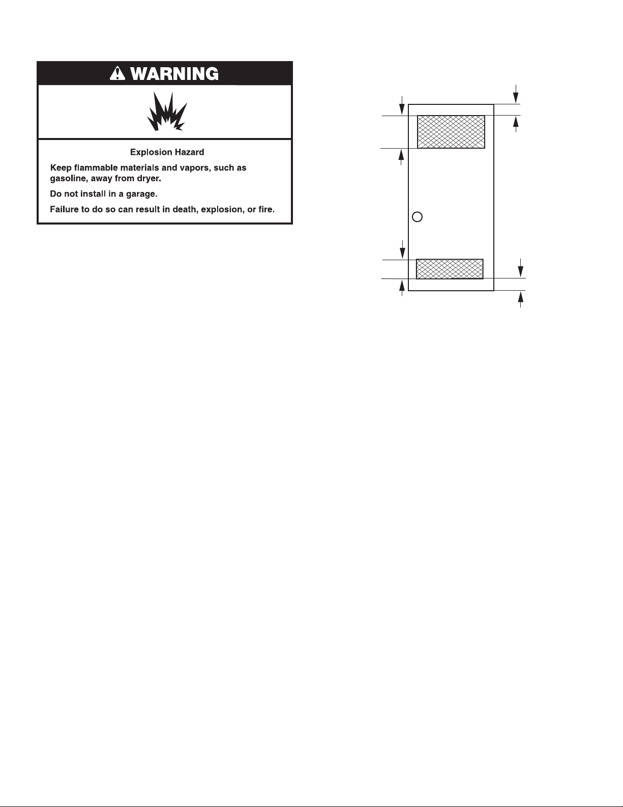
The washer/dryer must not be installed or stored in an area where
it will be exposed to water and/or weather.
Do not operate your washer in temperatures at or below 32ºF
(0ºC). Some water can remain in the washer and can cause
damage in low temperatures. See “Washer/Dryer Care” in the
Washer/Dryer Use and Care Guide for winterizing information.
Do not operate your dryer at temperatures below 45°F (7°C). At
lower temperatures, the dryer might not shut off at the end of an
automatic cycle. This can result in longer drying times.
Check code requirements. Some codes limit, or do not permit,
installation of the washer/dryer in garages, closets, mobile
homes, or sleeping quarters. Contact your local building
inspector.
Front
View
24 in.
2
2
)
Closet
door
3"
(76 mm)
The spacing dimensions above are recommended for this
washer/dryer. This washer/dryer has been tested for spacing of
0" (0 mm) clearance on the sides. Recommended spacing should
be considered for the following reasons:
nAdditional spacing should be considered for ease of
installation and servicing.
nAdditional clearances might be required for wall, door, and
oor moldings.
nAdditional spacing on all sides of the washer/dryer is
recommended to reduce noise transfer.
nFor closet installation, with a door, minimum ventilation
openings in the top and bottom of the door are required.
Louvered doors with equivalent ventilation openings are
acceptable.
Mobile Home – Additional Installation Requirements
This washer/dryer is suitable for mobile home installations.
The installation must conform to the Manufactured Home
Construction and Safety Standard, Title 24 CFR, Part 3280
(formerly the Federal Standard for Mobile Home Construction
and Safety, Title 24, HUD Part 280) or the Canadian
Manufactured Home Standard, CAN/CSA-Z240 MH.
Mobile home installations require:
nMetal exhaust system hardware, which is available for
purchase from your dealer.
nSpecial provisions must be made in mobile homes to
introduce outside air into the dryer. The opening (such as a
nearby window) should be at least twice as large as the dryer
exhaust opening.
6
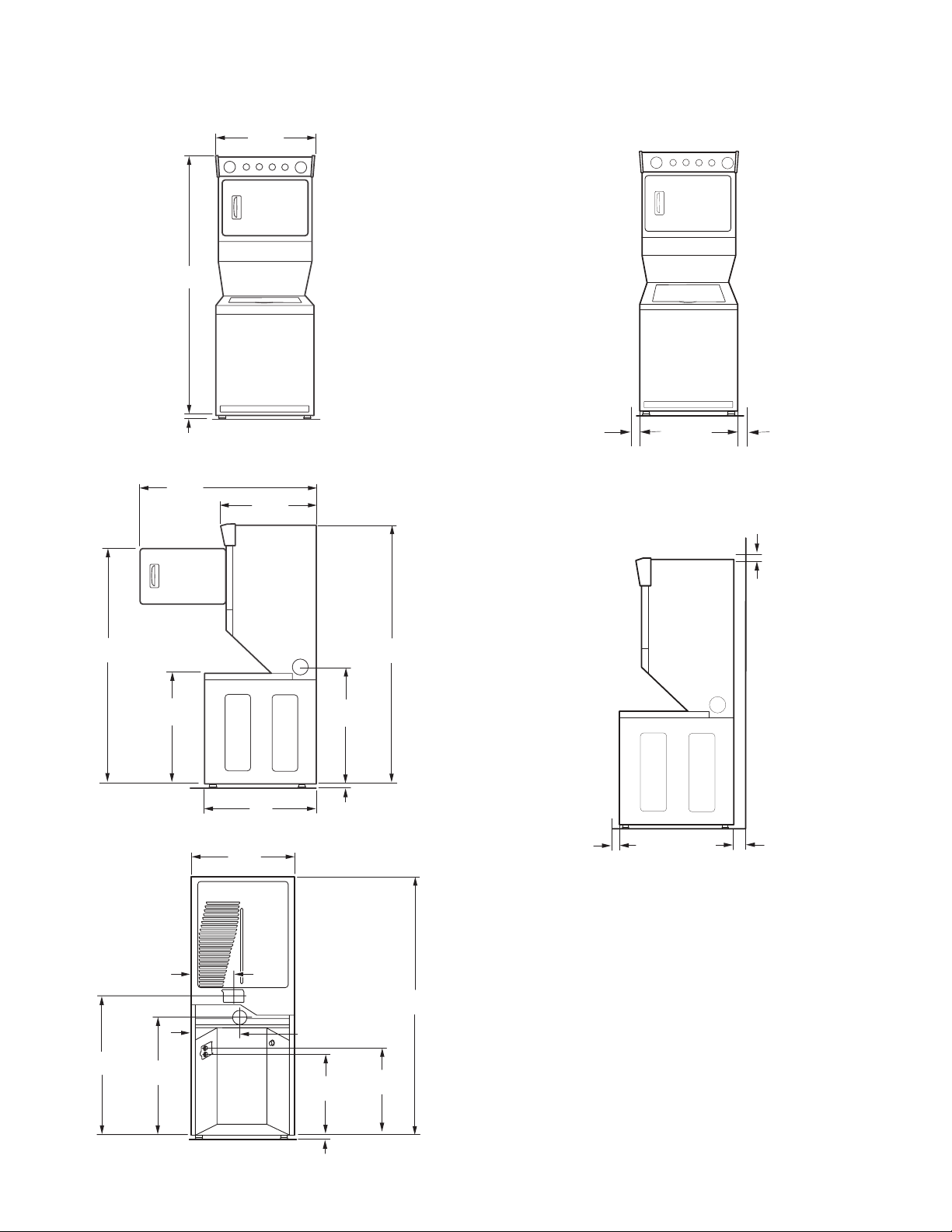
Dimensions/Clearances, 27" Models
(25 mm/0 mm)
(25 mm)
(Closet)
Dimensions
Front View
Side View
713/4"
(1822 mm)
1"
(25 mm)
7
/8"
58
(1495 mm)
1
27
/4"
(692 mm)
26"
(660 mm)
Clearances
Side Clearances (recommended/minimum)
1"/0"
(25 mm/0 mm)
Front/Back/Top Clearances (recommended/minimum)
1"/0"
(25 mm/0 mm)
1"/0"
653/4"
(1670 mm)
Back View
1
/4"
41
(1,048 mm)
321/8"
(816 mm)
11"
(279 mm)
1
/4"
35
(895 mm)
32"
(813 mm)
271/4"
(692 mm)
(864 mm)
(25 mm)
14"
(356 mm)
25"
(635 mm)
34"
1"
713/4"
(1822 mm)
(1822 mm)
261/2"
(673 mm)
713/4"
1"
5"
(127 mm)
1"
(25 mm)
7
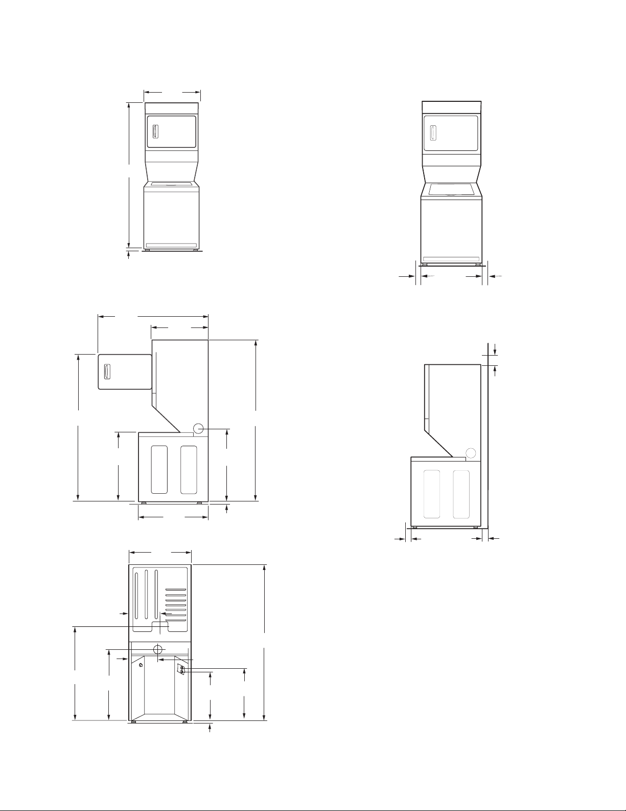
Dimensions/Clearances, 24" Models
Dimensions
Front View
Side View
703/4"
(1797 mm)
1"
(25 mm)
7
/8"
35
(911 mm)
7
23
/8"
(606 mm)
20
(521 mm)
Clearances
Side Clearances (recommended/minimum)
1"/0"
(25 mm/0 mm)
1
/2"
Front/Back/Top Clearances
1"/0"
(25 mm/0 mm)
12"
(305 mm)
653/4"
(1670 mm)
Back View
1
43
(1105 mm)
/2"
303/4"
(781 mm)
111/2"
(292 mm)
1
/4"
34
(870 mm)
267/8"
(683 mm)
237/8"
(606 mm)
(940 mm)
(25 mm)
14"
(356 mm)
26"
(660 mm)
37"
1"
(699 mm)
703/4"
(1797 mm)
703/4"
(1797 mm)
271/2"
1"
(25 mm)
(Closet)
5"
(127 mm)
*
**
1"
(25 mm)
**Required spacing.
** Rear clearance may be 0" (0 mm) when house exhaust system is lined up directly with dryer exhaust.
8
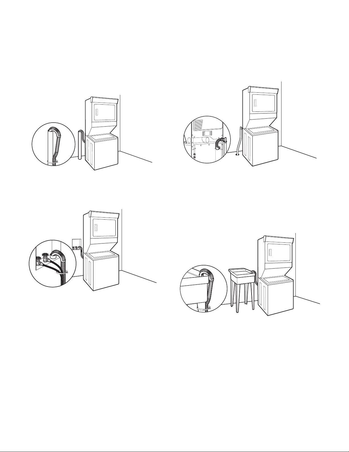
Drain System
Drain system can be installed using a oor drain, wall standpipe,
oor standpipe, or laundry tub. Select method you need.
Floor standpipe drain system
Minimum diameter for a standpipe drain: 2" (51 mm). Minimum
carry-away capacity: 17 gal. (64 L) per minute. Top of standpipe
must be at least 39" (991 mm) high; install no higher than 96"
(2.4 m) from bottom of washer/dryer. If you must install higher
than 96" (2.4 m), you will need a sump pump system.
Wall standpipe drain system
See requirements for oor standpipe drain system.
Floor drain system
Floor drain system requires a Siphon Break Kit (Part Number
285834), 2 Connector Kits (Part Number 285385), and an
Extension Drain Hose (Part Number 285863) that may be
purchased separately. To order, please see toll-free phone
numbers in your Use and Care Guide. Minimum siphon break:
28" (710 mm) from bottom of washer/dryer. (Additional hoses
may be needed.)
Laundry tub drain system
Minimum capacity: 20 gal. (76 L). Top of laundry tub must be
at least 39" (991 mm) above oor on 27" models, or 34" (864 mm)
above oor on 24" models; install no higher than 96" (2.4 m) from
bottom of washer/dryer.
IMPORTANT: To avoid siphoning, no more than 4.5" (114 mm)
of drain hose should be inside standpipe or below the top of
wash tub. Secure drain hose with shipping strap or plastic strap.
9
Electrical Requirements – U.S.A.
n
It is recommended that a separate circuit breaker serving only this
appliance be provided.
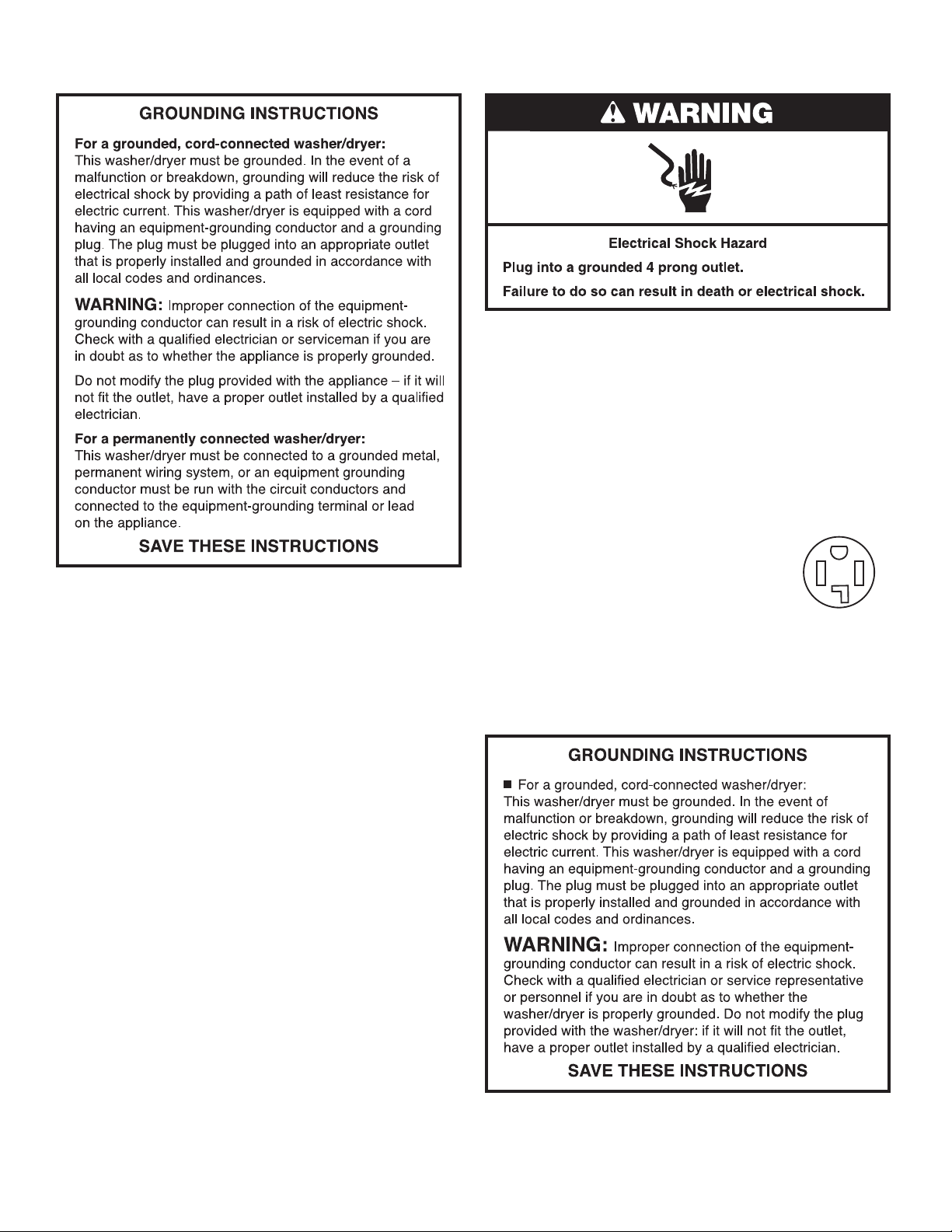
n To minimize possible shock hazard, the cord must be plugged
into a mating, 3- or 4-prong, grounding-type outlet, grounded
in accordance with local codes and ordinances. If a mating
outlet is not available, it is the personal responsibility and
obligation of the customer to have the properly grounded
outlet installed by a qualied electrician.
n If codes permit and a separate ground wire is used, it is
recommended that a qualied electrician determine that
the ground path is adequate.
n Check with a qualied electrician if you are not sure the
washer is properly grounded.
n Do not have a fuse in the neutral or ground circuit.
It is your responsibility:
n To contact a qualied electrical installer.
n To be sure that the electrical connection is adequate and in
conformance with the National Electrical Code, ANSI/NFPA
70-latest edition and all local codes and ordinances.
A copy of the above code standards can be obtained from:
National Fire Protection Association, One Batterymarch Park,
Quincy, MA 02269.
n To supply the required 3- or 4-wire, single phase, 120/240 volt,
60 Hz., AC only electrical supply (or 3- or 4-wire, 120/208 volt
electrical supply, if specied on the serial/rating plate) on a
separate 30-amp circuit, fused on both sides of the line. A
time-delay fuse or circuit breaker is recommended. Connect
to an individual branch circuit.
n Do not use an extension cord.
Electrical Connection
To properly install your washer/dryer, you must determine the
type of electrical connection you will be using and follow the
instructions provided for it here.
n This washer/dryer is manufactured ready to install with a
3-wire electrical supply connection. The neutral ground wire is
permanently connected to the neutral conductor (white wire)
within the dryer. If the dryer is installed with a 4-wire electrical
supply connection, the neutral ground wire must be removed
from the external ground connector (green screw), and
secured under the neutral terminal (center or white wire) of the
terminal block. When the neutral ground wire is secured under
the neutral terminal (center or white wire) of the terminal block,
the dryer cabinet is isolated from the neutral conductor.
n If local codes do not permit the connection of a neutral ground
wire to the neutral wire, see “Optional 3-wire connection” in
the “Electrical Connection” section.
n A 4-wire power supply connection must be used when the
appliance is installed in a location where grounding through
the neutral conductor is prohibited. Grounding through the
neutral is prohibited for (1) new branch-circuit installations,
(2) mobile homes, (3) recreational vehicles, and (4) areas
where local codes prohibit grounding through the neutral
conductors.
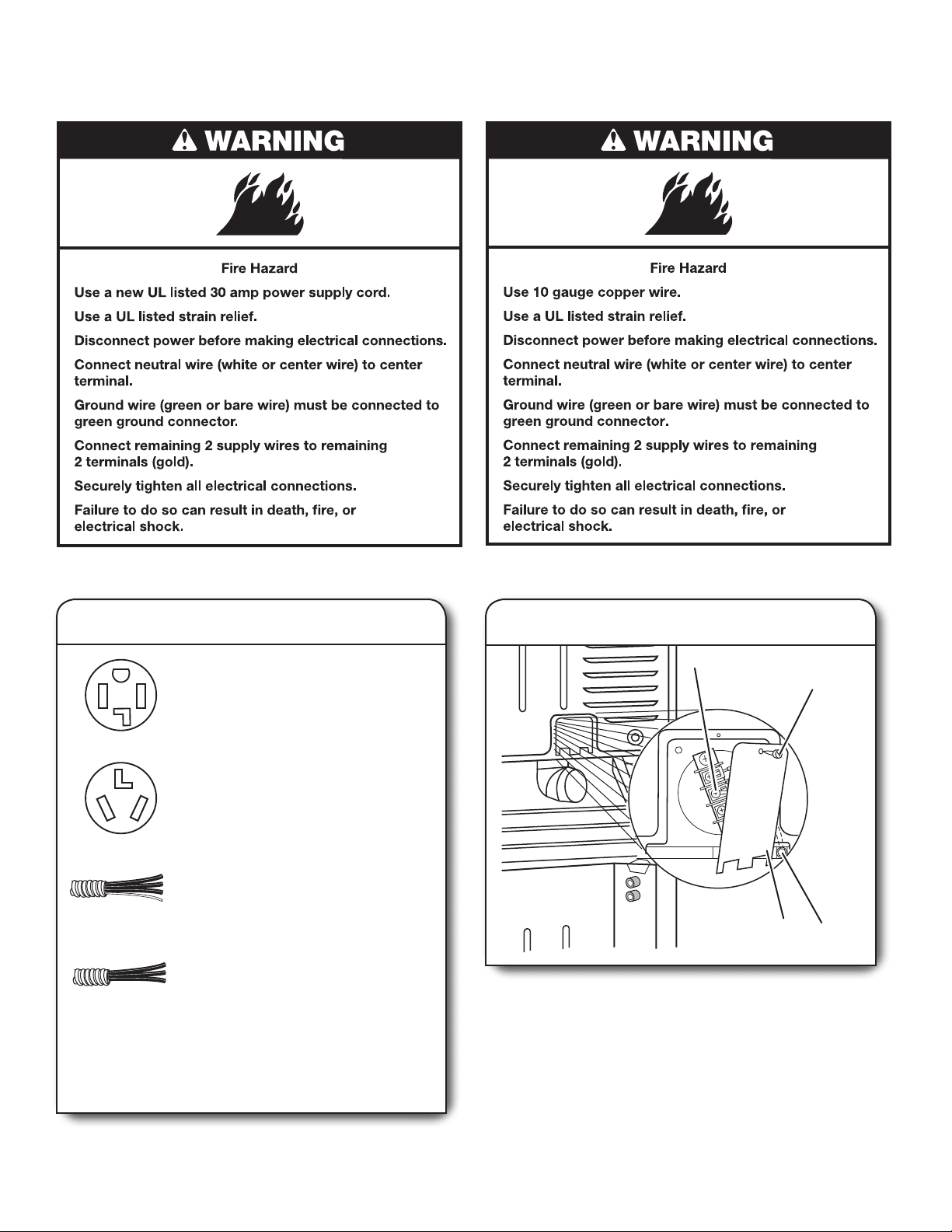
If using a power supply cord:
Use a UL listed power supply cord kit marked for use with
clothes dryers. The kit should contain:
n A UL listed 30-amp power supply cord, rated 120/240 volt
minimum. The cord should be type SRD or SRDT and be at
least 4 ft (1.22 m) long. The wires that connect to the dryer
must end in ring terminals or spade terminals with upturned
ends.
n A UL-listed strain relief.
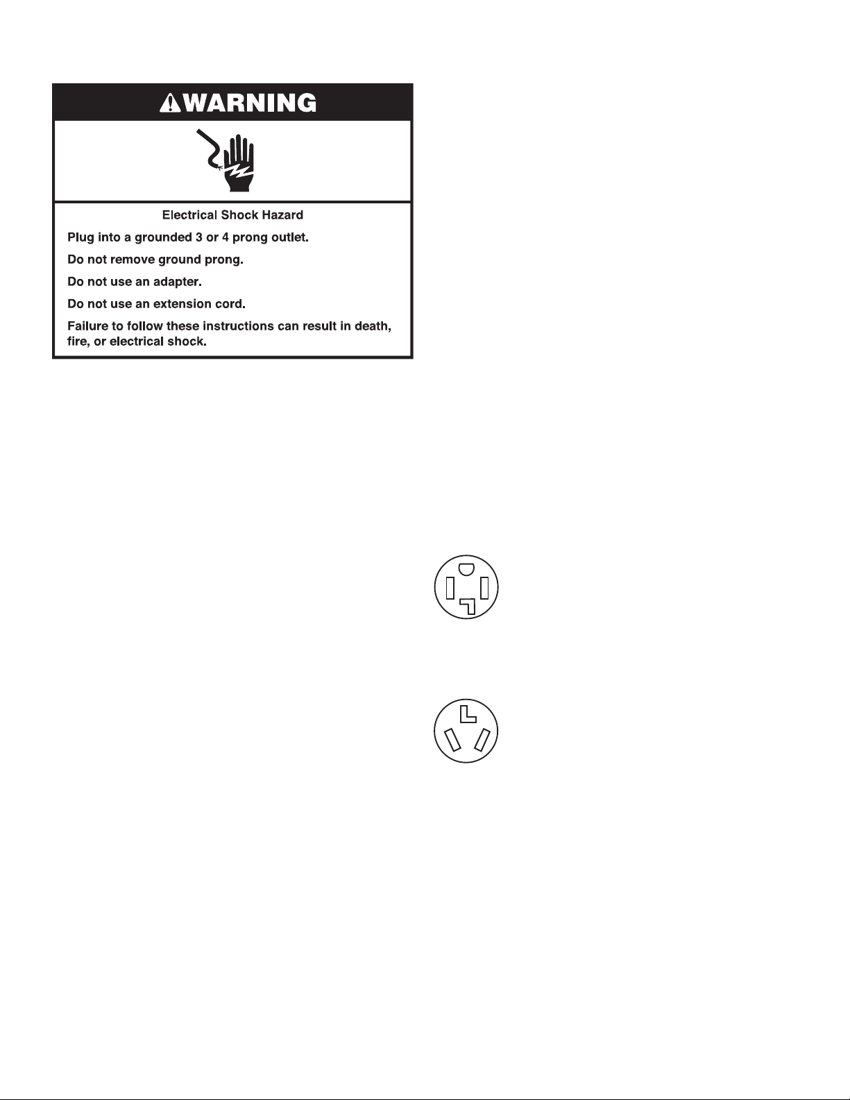
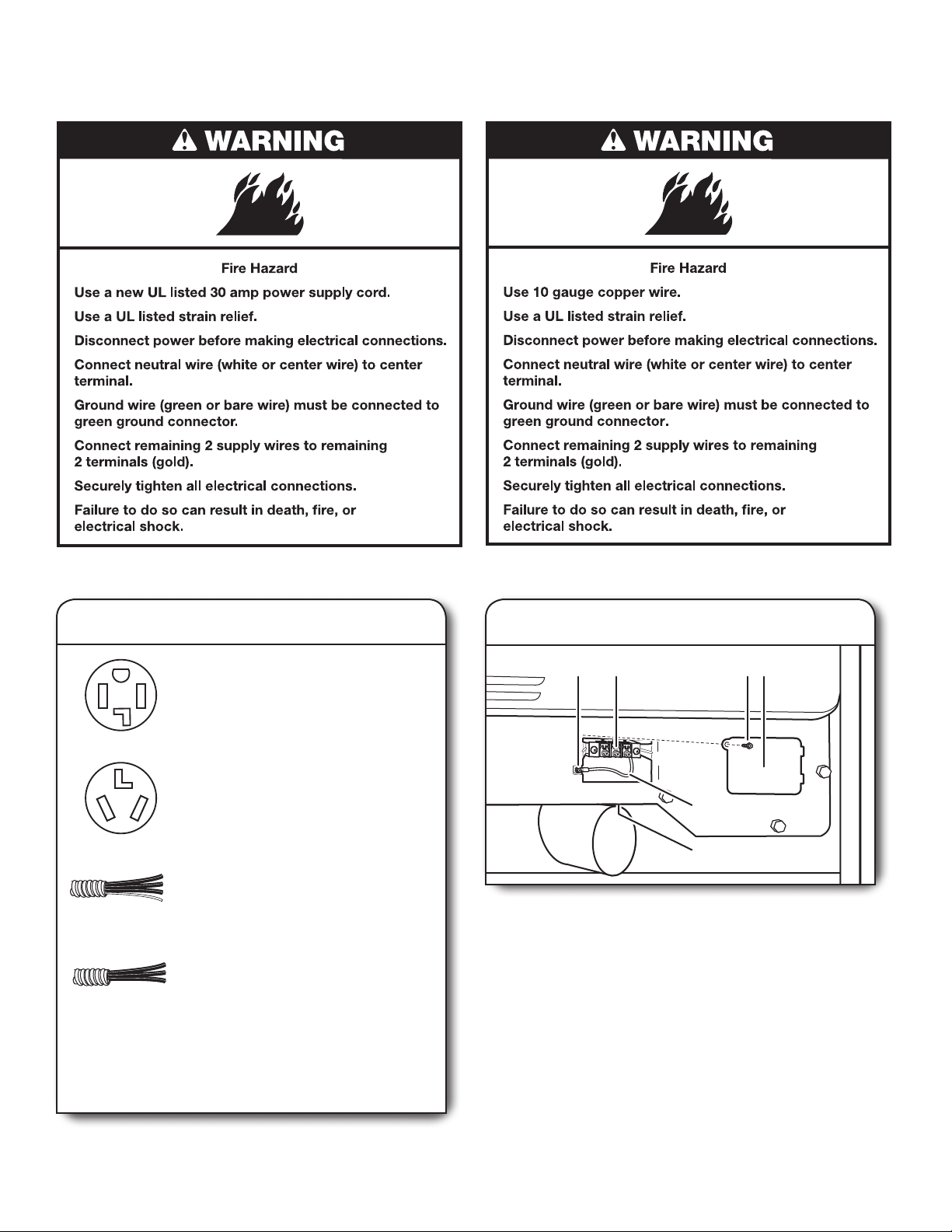
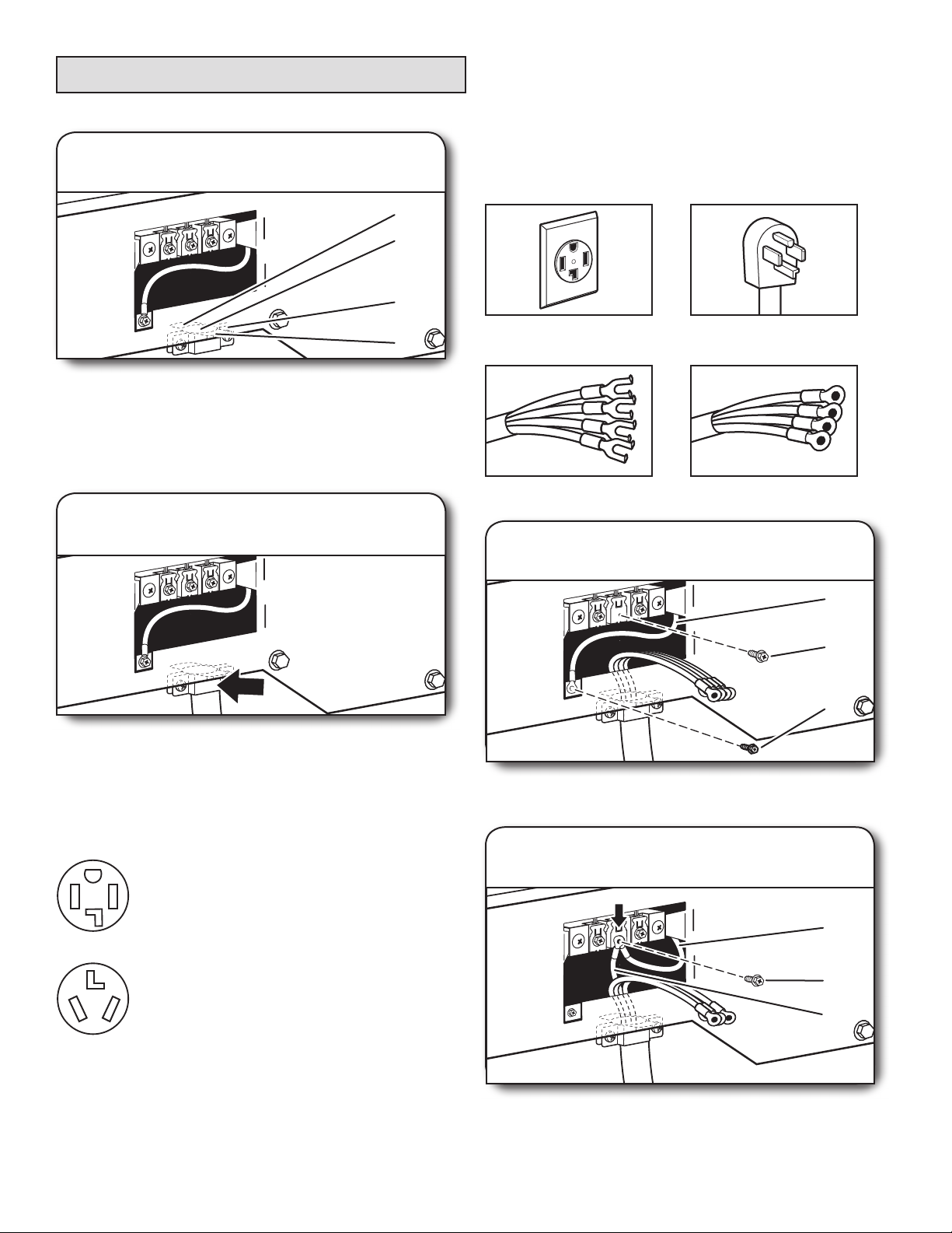
If your outlet looks like this:
Then choose a 4-wire power supply cord with ring
or spade terminals and UL-listed strain relief. The
4-wire power supply cord, at least 4 ft (1.22 m)
long, must have four 10-gauge copper wires and
match a 4-wire receptacle of NEMA Type 14-30R.
4-wire
receptacle
(14-30R)
The ground wire (ground conductor) may be either
green or bare. The neutral conductor must be
identied by a white cover.
If your outlet looks like this:
Then choose a 3-wire power supply cord with ring
or spade terminals and UL-listed strain relief. The
3-wire power supply cord, at least 4 ft (1.22 m) long,
must have three 10-gauge copper wires and match
a 3-wire receptacle of NEMA Type 10-30R.
3-wire
receptacle
(10-30R)
If connecting by direct wire:
Power supply cable must match power supply (4-wire or 3-wire)
and be:
n Flexible armored cable or nonmetallic sheathed copper
cable (with ground wire), covered with exible metallic
conduit. All current-carrying wires must be insulated.
n 10-gauge solid copper wire (do not use aluminum).
n At least 5 ft (1.52 m) long.
10
Electrical Requirements – Canada
It is your responsibility:
n To contact a qualied electrical installer.
n To be sure that the electrical connection is adequate and in
conformance with Canadian Electrical Code, C22.1 – latest
edition and all local codes. A copy of above codes standard
may be obtained from: Canadian Standards Association,
178 Rexdale Blvd., Toronto, ON M9W 1R3 CANADA.
n To supply the required 4-wire, single-phase, 120/240 volt,
60 Hz, AC-only electrical supply on a separate 30-amp circuit,
fused on both sides of the line. A time-delay fuse or circuit
breaker is recommended. Connect to an individual branch
circuit.
n This dryer is equipped with a CSA
International Certied Power Cord
intended to be plugged into a standard
14-30R wall receptacle. The cord is 5 ft.
(1.52 m) long. Be sure wall receptacle is
within reach of dryer’s nal location.
If using a replacement power supply cord, it is recommended that
you use Power Supply Cord Replacement Part Number 9831317.
For further information, please reference service numbers located
in “Assistance or Service” section of your Use and Care Guide.
4-wire receptacle
(14-30R)
11
Remove Shipping Strap (27" models)
To avoid oor damage, set washer/dryer onto cardboard before
moving across oor. Move washer/dryer close to its nal location.
1. Remove strap, hang tag, and pin
Cut the shipping strap about 16" (406 mm) from the plug end.
Look for the words “CUT HERE.” Discard end with cotter pins.
You will use the remaining piece of shipping strap to secure
the drain hose.
3. Cut shipping strap
CUT HERE
Do not cut yellow strap. Pull yellow strap rmly until completely
removed from washer/dryer. There should be 2 cotter pins on
the end of the shipping strap. Remove the hang tag and pin
from the vent pipe.
2. Check rear leveling legs
Tilt the washer/dryer forward. Move each of the 2 rear legs in
an up-down motion to check the self-adjusting leveling legs
for free movement. This is required for proper leveling. Gently
lower the washer/dryer to the oor.
12
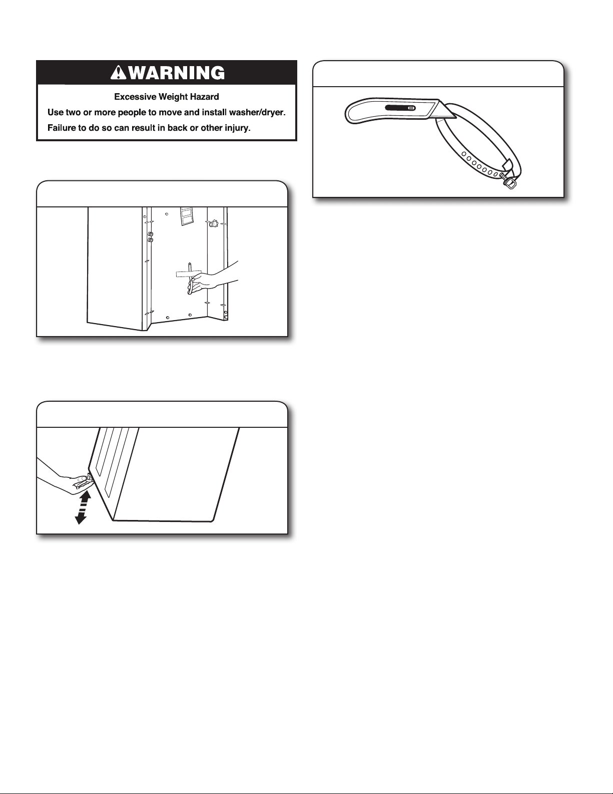
Install Leveling Legs (27" models) Install Leveling Legs (24" models)
To protect the oor, use a large at piece of cardboard from the
shipping carton. Gently place the washer/dryer on its side, on
1. Prepare to install leveling feet
the cardboard.
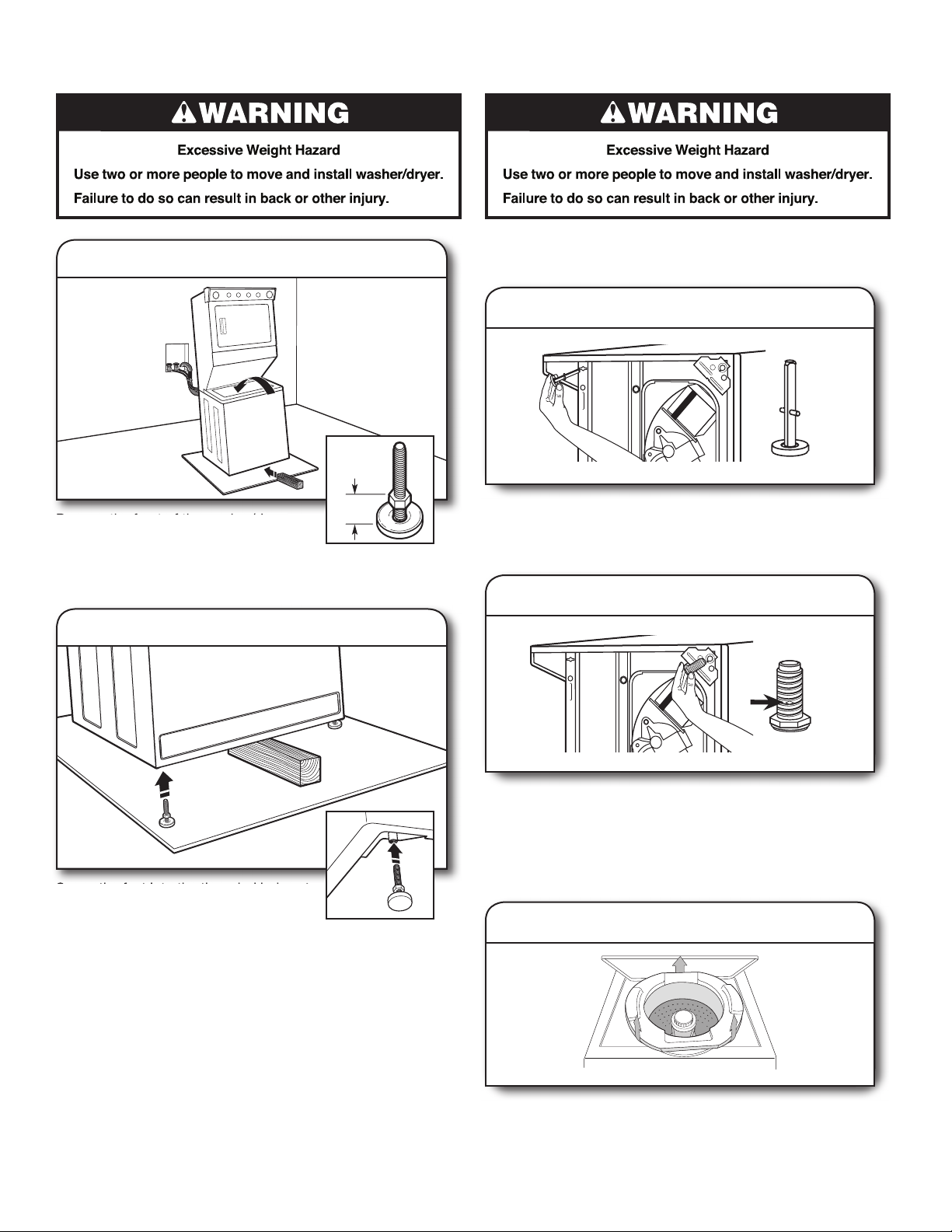
1. Install rear leveling legs
1"
(25 mm)
Prop up the front of the washer/dryer
about 4" (102 mm) with a wood block
or similar object that will support the
weight of the washer/dryer. Then screw the locknut onto each
foot to within 1" (25 mm) of the foot base.
2. Install front leveling feet
Screw the feet into the threaded holes at
the front corners of the washer/dryer until
the jam nuts touch the washer.
NOTE: Do not tighten the nuts until the washer/dryer is level.
Tilt the washer/dryer back and remove the wood block. Gently
lower the washer/dryer to the oor.
Push legs into holes in rear corners until they snap into place.
Check adjustability of rear legs by pushing in one leg. The
other leg should come out. Check both legs. If they do not
move freely, repeat procedure.
2. Install front leveling legs
Examine front leveling legs; nd diamond marking. Screw front
legs by hand into holes in triangular braces in front corners.
Use wrench to nish turning the legs until diamond marking is
no longer visible. Gently stand the washer/dryer upright.
Remove Foam Packing (24" models)
1. Pull foam packing ring out of washer
Open the washer lid. The latch under the dryer will keep
the lid open. Pull the foam packing ring out of the washer.
NOTE: Keep the foam ring and use it when transporting
your washer/dryer. This packing material is used to keep
the washer tub stable during transport.
13
Electrical Connection, 27" models (U.S.A. Only)
Power Supply Cord Direct Wire
Electrical Connection Options
1. Choose electrical connection type
Power supply cord 4-wire receptacle
(NEMA Type 14-30R): Go to “4-Wire
Power Supply Cord Connection” section.
Then, go to “Venting Requirements.”
Power supply cord 3-wire receptacle
(NEMA Type 10-30R): Go to “3-Wire
Power Supply Cord Connection” section.
Then go to “Venting Requirements.”
4-wire direct connection: Go to “4-Wire
Direct Wire Connection” section. Then go
to “Venting Requirements.”
3-wire direct connection: Go to “3-Wire
Direct Wire Connection” section. Then go
to “Venting Requirements.”
NOTE: If local codes do not permit connection of a
cabinet-ground conductor to neutral wire, go to “Optional
3-Wire Connection” section. This connection may be
used with either a power supply cord or a direct wire
connection.
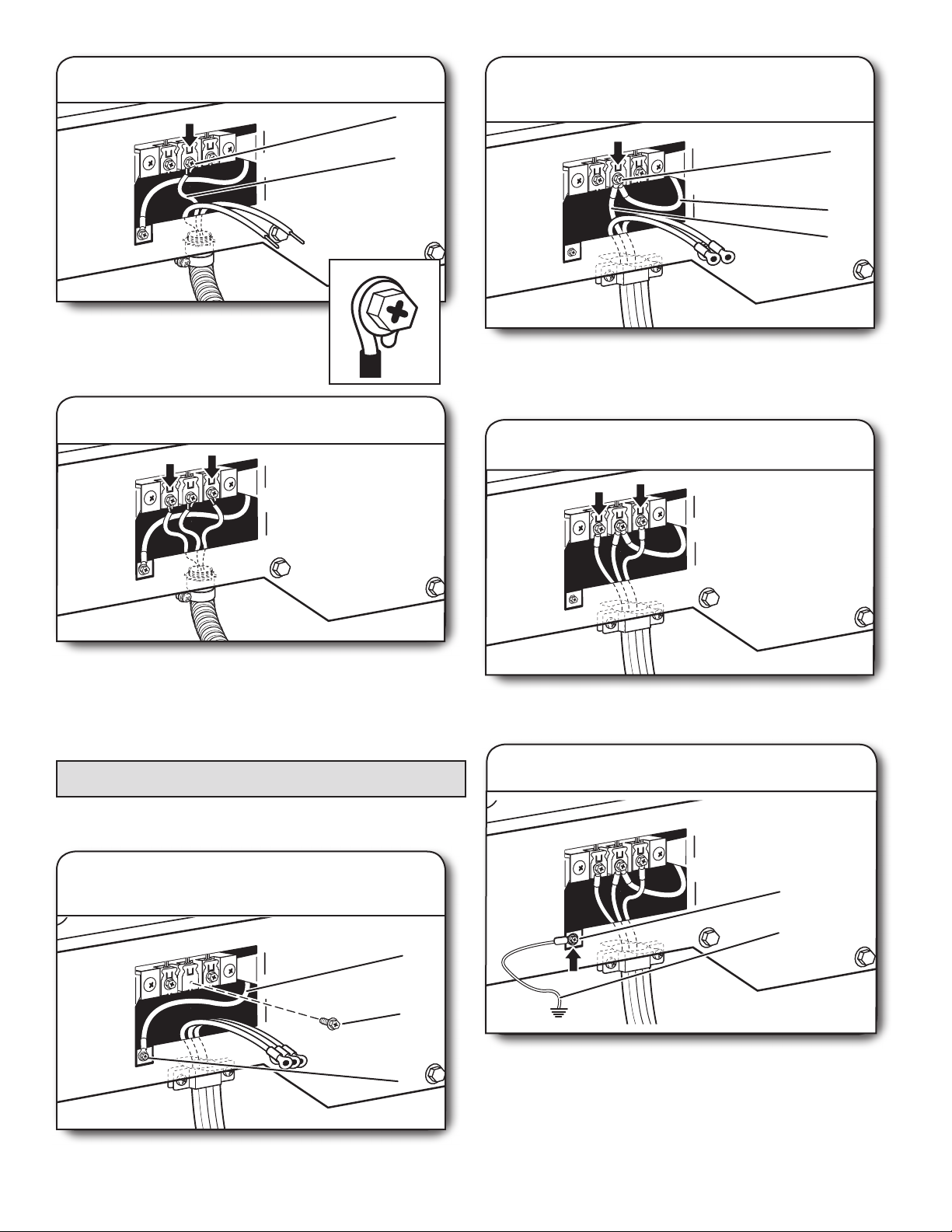
2. Remove terminal block cover
BC D
E
F
Before you start, disconnect power. Remove hold-down
screw (D) and terminal block cover (A).
A. Terminal block cover
B. External ground conductor screw
C. Center terminal block screw
D. Hold-down screw
E. Neutral ground wire
F. Hole below terminal block cover
A
14
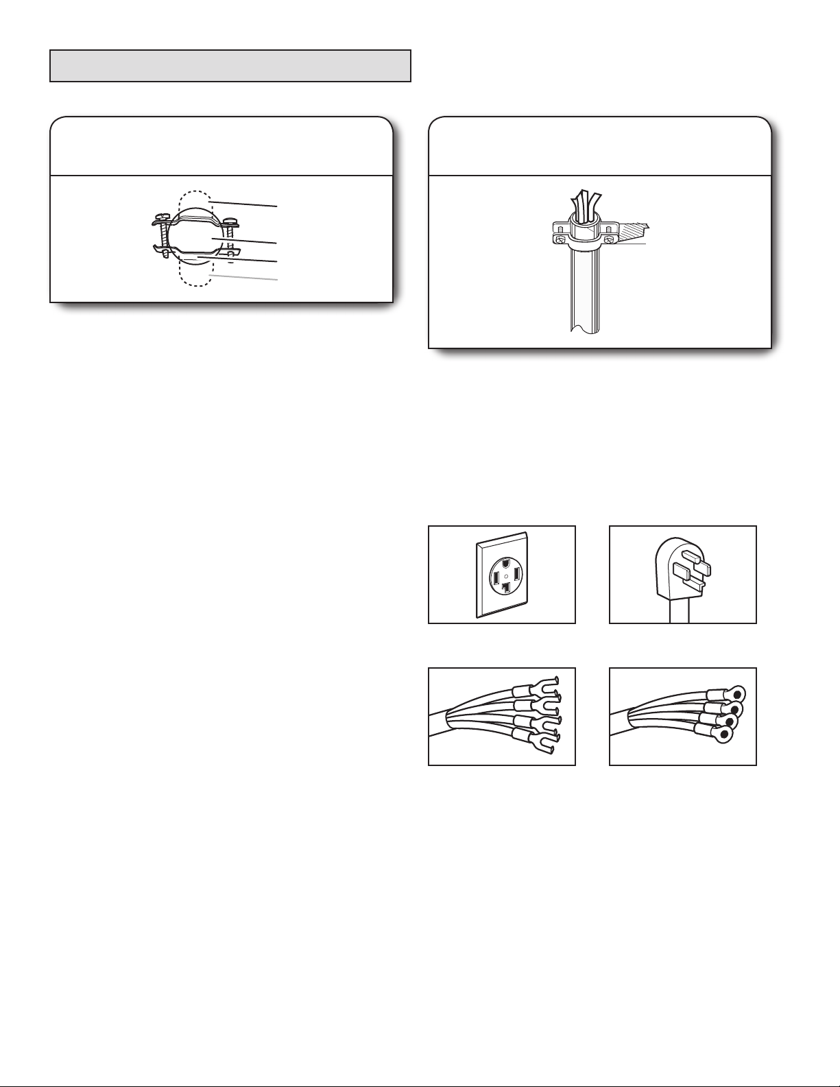
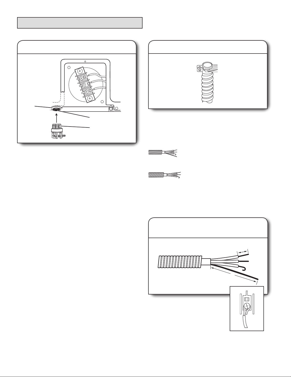
Power Supply Cord Connection
Power Supply Cord Strain Relief
1. Attach power supply cord
strain relief
A
B
C
D
Remove the screws from a 3/4" (19 mm) UL-listed strain relief
(UL marking on strain relief). Put the tabs of the two clamp
sections (C) into the hole below the terminal block opening
(B) so that one tab is pointing up (A) and the other is pointing
down (D), and hold in place. Tighten strain relief screws just
enough to hold the two clamp sections (C) together.
2. Attach power supply cord
to strain relief
4-Wire Power Supply Cord Connection
IMPORTANT:
homes and where local codes do not permit the use of 3-wire
connections.
4-wire receptacle
(NEMA type 14-30R)
Spade terminals with
upturned ends
A 4-wire connection is required for mobile
4-prong plug
Ring terminals
1. Prepare to connect neutral
ground wire and neutral wire
Put power supply cord through the strain relief. Be sure that
the wire insulation on the power supply cord is inside the
strain relief. The strain relief should have a tight t with the
dryer cabinet and be in a horizontal position. Do not further
tighten strain relief screws at this point.
If your outlet looks like this:
Power supply cord 4-wire receptacle
(NEMA Type 14-30R):
Go to “4-Wire Power Supply Cord
Connection” on this page.
Power supply cord 3-wire receptacle
(NEMA Type 10-30R):
Go to “3-Wire Power Supply Cord
Connection” on page 16.
E
B
A
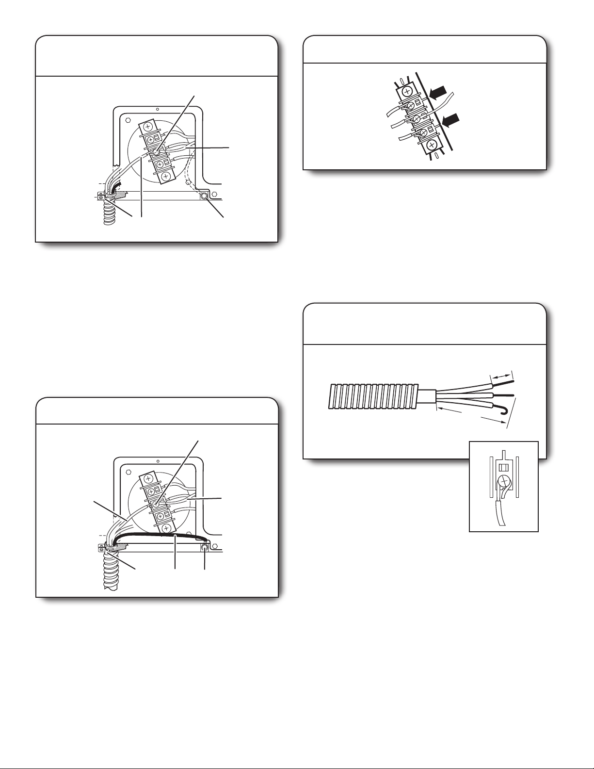
Remove center terminal block screw (B). Remove neutral
ground wire (E) from external ground conductor screw (A).
2. Connect neutral ground wire
and neutral wire
E
B
C
Connect neutral ground wire (E) and neutral wire (white or
center) (C) of power supply cord under center terminal block
screw (B). Tighten screw.
15
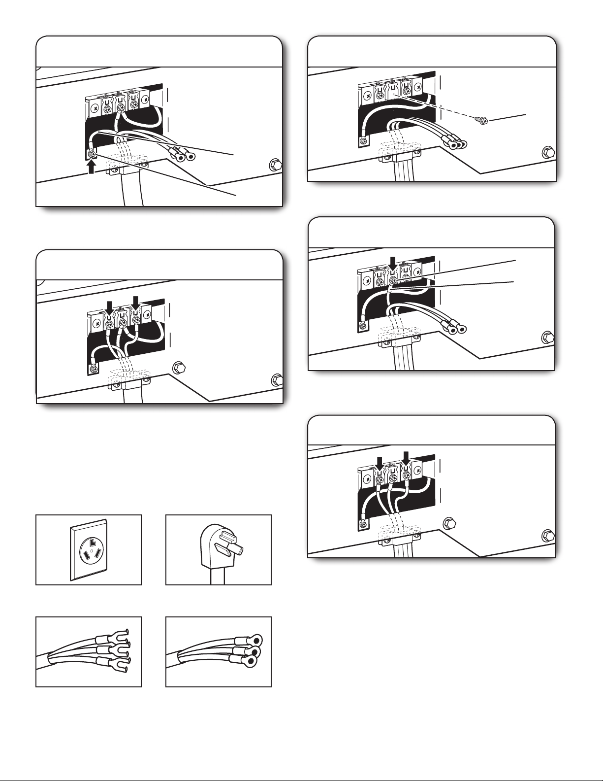
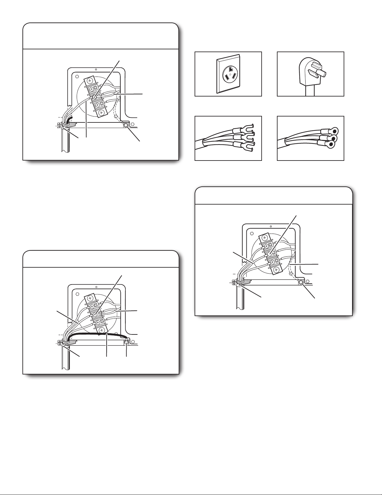
3. Connect ground wire
1. Remove center screw
B
F
A
Connect ground wire (F) (green or bare) of power supply cord
to external ground conductor screw (A). Tighten screw.
4. Connect remaining wires
Connect remaining wires to outer terminal block screws.
Tighten screws. Finally, reinsert tab of terminal block cover
into slot of dryer rear panel. Secure cover with hold-down
screw. Now, go to “Venting Requirements.”
3-Wire Power Supply Cord Connection
IMPORTANT: Use where local codes permit connecting
cabinet-ground conductor to neutral wire.
Remove center terminal block screw (B).
2. Connect neutral wire
B
C
Connect neutral wire (white or center) (C) of power supply cord
to center terminal block screw (B). Tighten screw.
3. Connect remaining wires
3-wire receptacle
(NEMA type 10-30R)
Spade terminals with
upturned ends
16
3-prong plug
Ring terminals
Connect remaining wires to outer terminal block screws.
Tighten screws. Finally, reinsert tab of terminal block cover
into slot of dryer rear panel. Secure cover with hold-down
screw. Now, go to “Venting Requirements.”
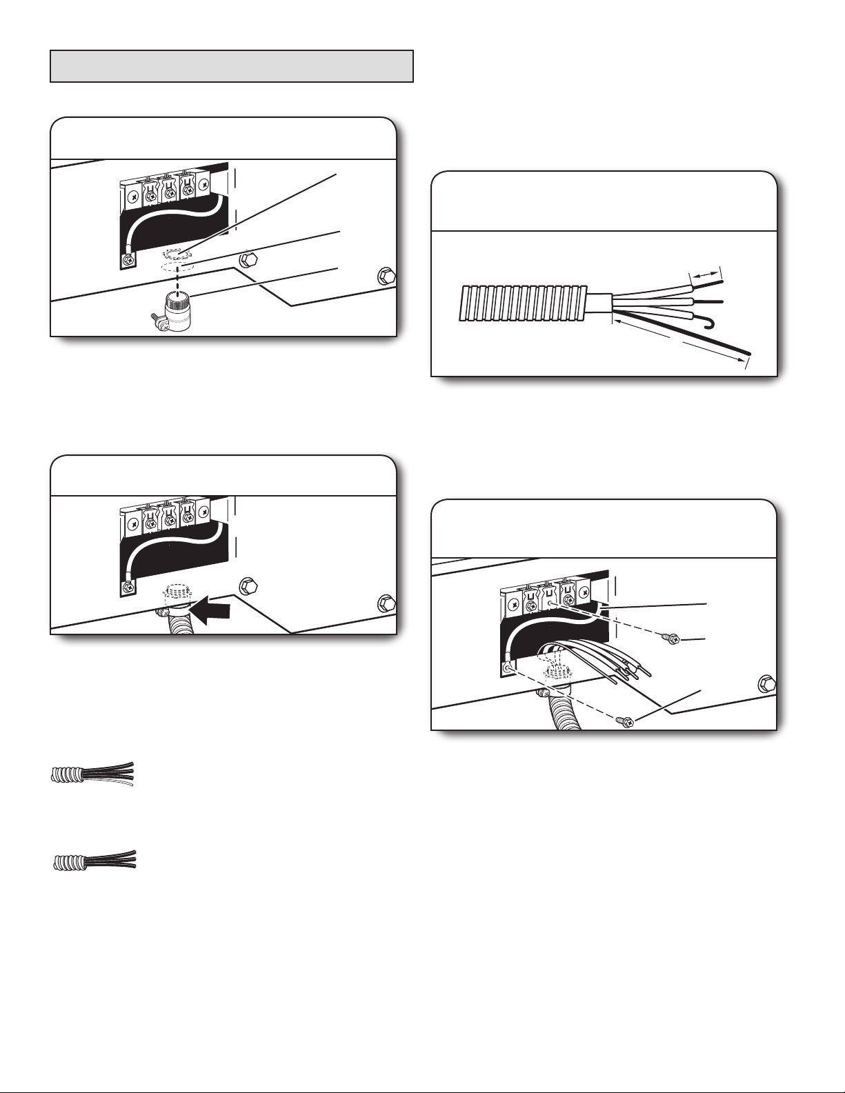
Direct Wire Connection
Direct Wire Strain Relief
1. Attach direct wire strain relief
A
B
C
Unscrew the removable conduit connector (A) and any
screws from a 3/4" (19 mm) UL listed strain relief (UL marking
on strain relief). Put the threaded section of the strain relief
(C) through the hole below the terminal block opening (B).
Reaching inside the terminal block opening, screw the
removable conduit connector (A) onto the strain relief threads.
2. Attach direct wire cable to strain relief
4-Wire Direct Wire Connection
IMPORTANT: A 4-wire connection is required for mobile
homes and where local codes do not permit 3-wire
connections.
1. Prepare your 4-wire cable for direct
connection
1"
(25 mm)
5"
(127 mm)
Direct wire cable must have 5 ft. (1.52 m) of extra length so
washer/dryer may be moved if needed.
Strip 5" (127 mm) of outer covering from end of cable,
leaving bare ground wire at 5" (127 mm). Cut 11/2" (38 mm)
from remaining 3 wires. Strip insulation back 1" (25 mm).
Shape ends of wires into hooks.
Put direct wire cable through the strain relief. The strain
relief should have a tight t with the dryer cabinet and be in
a horizontal position. Tighten strain relief screw against the
direct wire cable.
If your wiring looks like this:
4-wire direct wire connection:
Go to “4-Wire Direct Wire Connection”
on this page.
3-wire direct wire connection:
Go to “3-Wire Direct Wire Connection”
on page 18.
2. Prepare to connect neutral ground
wire and neutral wire
E
B
A
Remove center terminal block screw (B). Remove neutral
ground wire (E) from external ground conductor screw (A).
17
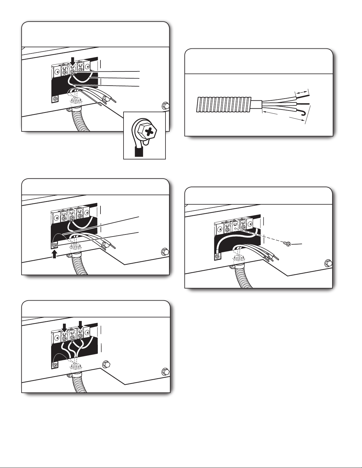
3. Connect neutral ground wire
and neutral wire
3-Wire Direct Wire Connection
IMPORTANT: Use where local codes permit connecting
cabinet-ground conductor to neutral wire.
1. Prepare your 3-wire cable
B
E
C
for direct connection
1"
(25 mm)
3½"
(89 mm)
Connect neutral ground wire (E) and place
hooked end (hook facing right) of neutral
wire (white or center wire) (C) of direct
wire cable under center screw of terminal
block (B). Squeeze hooked ends together
and tighten screw.
4. Connect ground wire
F
A
Connect ground wire (green or bare) (F) of direct wire cable
to external ground conductor screw (A). Tighten screw.
Direct wire cable must have 5 ft. (1.52 m) of extra length so
washer/dryer may be moved if needed.
1
/2" (89 mm) of outer covering from end of cable. Strip
Strip 3
insulation back 1" (25 mm). If using 3-wire cable with ground
wire, cut bare wire even with outer covering. Shape wire ends
into hooks.
2. Remove center screw
B
Remove center terminal block screw (B).
5. Connect remaining wires
Place hooked ends of remaining direct wire cable wires
under outer terminal block screws (hooks facing right).
Squeeze hooked ends together and tighten screws. Finally,
reinsert tab of terminal block cover into slot of dryer rear
panel. Secure cover with hold-down screw. Now, go to
“Venting Requirements.”
18
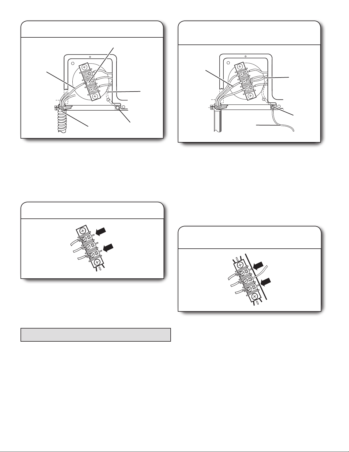
A
G
3. Connect neutral wire
2. Connect neutral ground wire
B
and neutral wire
Place hooked end of neutral wire (white or
center) (C) of direct wire cable under center
terminal block screw (B). Squeeze hooked
end together. Tighten screw.
4. Connect remaining wires
C
Connect neutral ground wire (E) and neutral wire (white or
center wire) (C) of power supply cord or cable under center
terminal block screw (B). Tighten screw.
B
E
C
3. Connect remaining wires
Place hooked ends of remaining direct wire cable wires
under outer terminal block screws (hooks facing right).
Squeeze hooked ends together and tighten screws. Finally,
reinsert tab of terminal block cover into slot of dryer rear
panel. Secure cover with hold-down screw. Now, go to
“Venting Requirements.”
Optional 3-Wire Connection
IMPORTANT: You must verify with a quali ed electrician that
this grounding method is acceptable before connecting.
1. Prepare to connect neutral
ground wire and neutral wire
E
B
Remove center terminal block screw (B). Remove neutral
ground wire (E) from external ground conductor screw (A).
A
Place remaining wires under outer terminal block screws
(hooks facing right). Tighten screws.
4. Connect external ground wire
Connect a separate copper ground wire (G) from the external
ground conductor screw (A) to an adequate ground. Finally,
reinsert tab of terminal block cover into slot of dryer rear
panel. Secure cover with hold-down screw. Now, go to
“Venting Requirements.”
19
Electrical Connection, 24" models (U.S.A. Only)
Power Supply Cord Direct Wire
Electrical Connection Options
1. Choose electrical connection type
Power supply cord 4-wire receptacle
(NEMA Type 14-30R): Go to “4-Wire
Power Supply Cord Connection” section.
Then, go to “Venting Requirements.”
Power supply cord 3-wire receptacle
(NEMA Type 10-30R): Go to “3-Wire
Power Supply Cord Connection” section.
Then go to “Venting Requirements.”
4-wire direct connection: Go to “4-Wire
Direct Wire Connection” section. Then go
to “Venting Requirements.”
3-wire direct connection: Go to “3-Wire
Direct Wire Connection” section. Then go
to “Venting Requirements.”
NOTE: If local codes do not permit connection of a
cabinet-ground conductor to neutral wire, go to “Optional
3-Wire Connection” section. This connection may be
used with either a power supply cord or a direct wire
connection.
2. Remove terminal block cover
A
B
D
C
Before you start, disconnect power. Remove hold-down
screw (B) and terminal block cover (C).
A. Center terminal block screw
B. Hold-down screw
C. Terminal block cover
D. External ground conductor screw
20
A
B
C
D
Power Supply Cord Connection
Power Supply Cord Strain Relief
1. Attach power supply cord
strain relief
Remove the screws from a 3/4" (19 mm) UL listed strain relief
(UL marking on strain relief). Put the tabs of the two clamp
sections (C) into the hole below the terminal block opening
(B) so that one tab is pointing up (A) and the other is pointing
down (D), and hold in place. Tighten strain relief screws just
enough to hold the two clamp sections (C) together.
A. Strain relief tab pointing up
B. Hole below terminal block opening
C. Clamp section
D. Strain relief tab pointing down
2. Attach power supply cord
to strain relief
Put power supply cord through the strain relief. Be sure that
the wire insulation on the power supply cord is inside the
strain relief. The strain relief should have a tight t with the
dryer cabinet and be in a horizontal position. Do not further
tighten strain relief screws at this point.
4-Wire Power Supply Cord Connection
IMPORTANT: A 4-wire connection is required for mobile
homes and where local codes do not permit the use of
3-wire connections.
4-wire receptacle
(NEMA type 14-30R)
Spade terminals
with upturned ends
4-prong plug
Ring terminals
21
1. Connect neutral ground wire
A
B
B
and neutral wire
3-Wire Power Supply Cord Connection
Use where local codes permit connecting cabinet-ground
conductor to neutral wire.
E
D
Remove center terminal block screw. Remove neutral ground
wire from external ground conductor screw. Connect neutral
ground wire and the neutral wire (white or center wire)
of power supply cord under center terminal block screw.
Tighten screw.
A. Center terminal block screw
B. Neutral ground wire
C. External ground conductor screw – Dotted
line shows position of NEUTRAL ground
wire before being moved to center terminal
block screw.
D. Neutral wire (white or center wire)
E. 3/4" (19 mm) UL listed strain relief
C
2. Connect ground wire
3-wire receptacle
(NEMA type 10-30R)
Spade terminals
with upturned ends
1. Connect neutral wire
A
3-prong plug
Ring terminals
B
C
A
F
Connect ground wire (green or bare) of power supply cord
to external ground conductor screw. Tighten screw.
A. Neutral wire (white or center wire)
B. Center terminal block screw
C. Neutral ground wire
D. External ground conductor screw
E. Ground wire (green or bare) of power
supply cord
F. 3/4" (19 mm) UL listed strain relief
Connect the other wires to outer terminal block screws. Tighten
screws. Tighten strain relief screws. Insert tab of terminal block
cover into slot of dryer rear panel. Secure cover with hold-down
screw. Now go to “Venting Requirements”.
E
C
D
22
E
Loosen or remove center terminal block screw. Connect neutral
wire (white or center wire) of power supply cord to the center
terminal screw of the terminal block. Tighten screw.
A. Neutral wire (white or center wire)
B. Center terminal block screw
C. Neutral ground wire
D. External ground conductor screw
E. 3/4" (19 mm) UL listed strain relief
Connect the other wires to outer terminal block screws. Tighten
screws. Tighten strain relief screws. Insert tab of terminal block
cover into slot of dryer rear panel. Secure cover with hold-down
screw. Now go to “Venting Requirements”.
D
Direct Wire Connection
Direct Wire Strain Relief
1. Attach direct wire strain relief
A
2.
Attach direct wire cable to strain relief
B
C
Unscrew the removable conduit connector and any screws
from a 3/4" (19 mm) UL listed strain relief (UL marking on
strain relief). Put the threaded section of the strain relief
through the hole below the terminal block opening. Reaching
inside the terminal block opening, screw the removable
conduit connector onto the strain relief threads.
A. Removable conduit connector
B. Hole below terminal block opening
C. Strain relief threads
Put direct wire cable through the strain relief. The strain
relief should have a tight t with the dryer cabinet and be in
a horizontal position. Tighten strain relief screw against the
direct wire cable.
If your wiring looks like this:
4-wire direct connection:
Go to “4-Wire Direct Wire Connection”
on this page.
3-wire direct connection:
Go to “3-Wire Direct Wire Connection”.
4-Wire Direct Wire Connection
IMPORTANT: A 4-wire connection is required for mobile
homes and where local codes do not permit the use of
3-wire connections.
1. Prepare your 4-wire cable
for direct connection
1"
(25 mm)
5"
(127 mm)
Direct wire cable must have 5 ft. (1.52 m)
of extra length so washer/dryer can
be moved if needed.
Strip 5" (127 mm) of outer covering
from end of cable, leaving bare ground
wire at 5" (127 mm). Cut 1-1/2" (38 mm)
from remaining 3 wires. Strip insulation
back 1" (25 mm). Shape ends of wires into a hook shape.
When connecting to the terminal block, place the hooked end
of the wire under the screw of the terminal block (hook facing
right), squeeze hooked end together, and tighten screw. See
example above.
23
2. Connect neutral ground wire
A
A
B
(89 mm)
and neutral wire
E
D
4. Connect remaining wires
B
Place the hooked ends of the other direct wire cable wires
under the outer terminal block screws (hooks facing right).
Squeeze hooked ends together. Tighten screws. Tighten
C
strain relief screw. Insert tab of terminal block cover into slot
of dryer rear panel. Secure cover with hold-down screw. Now
go to “Venting Requirements”.
Remove center terminal block screw. Remove neutral ground
wire from external ground conductor screw. Connect neutral
ground wire and place the hooked end (hook facing right)
of the neutral wire (white or center wire) of direct wire cable
under the center screw of the terminal block. Squeeze hooked
ends together. Tighten screw.
A. Center terminal block screw
B. Neutral ground wire
C. External ground conductor screw – Dotted
line shows position of NEUTRAL ground
wire before being moved to center terminal
block screw.
D. Neutral wire (white or center wire)
E. 3/4" (19 mm) UL listed strain relief
3. Connect ground wire
C
F
E
D
3-Wire Direct Wire Connection
Use where local codes permit connecting cabinet-ground
conductor to neutral wire.
1. Prepare your 3-wire cable
for direct connection
1"
(25 mm)
3½"
Direct wire cable must have 5 ft. (1.52 m)
of extra length so washer/dryer can
be moved if needed.
Strip 3-1/2" (89 mm) of outer covering
from end of cable. Strip insulation back
1" (25 mm). If using 3-wire cable with
ground wire, cut bare wire even with
outer covering. Shape ends of wires into a hook shape.
When connecting to the terminal block, place the hooked end
of the wire under the screw of the terminal block (hook facing
right), squeeze hooked end together, and tighten screw. See
example above.
Connect ground wire (green or bare) of direct wire cable
to external ground conductor screw. Tighten screw.
A. Neutral wire (white or center wire)
B. Center terminal block screw
C. Neutral ground wire
D. External ground conductor screw
E. Ground wire (green or bare) of direct
wire cable
F. 3/4" (19 mm) UL listed strain relief
24
2. Connect neutral wire
B
1. Connect neutral ground wire
and neutral wire
A
C
E
Loosen or remove center terminal block screw. Place the
hooked end of the neutral wire (white or center wire) of direct
wire cable under the center screw of terminal block (hook
facing right). Squeeze hooked end together. Tighten screw.
A. Neutral wire (white or center wire)
B. Center terminal block screw
C. Neutral ground wire
D. External ground conductor screw
E. 3/4" (19 mm) UL listed strain relief
D
3. Connect remaining wires
A
B
C
D
Remove center terminal block screw. Remove neutral ground
wire from external ground conductor screw. Connect neutral
ground wire and the neutral wire (white or center wire) of
power supply cord/cable under center terminal block screw.
Tighten screw.
A. Neutral wire (white or center wire)
B. Neutral ground wire
C. External ground conductor screw – Dotted
line shows position of NEUTRAL ground
wire before being moved to center terminal
block screw.
D. Grounding path determined by a quali ed
electrician
2. Connect remaining wires and
connect separate ground wire
Place the hooked ends of the other direct wire cable wires
under the outer terminal block screws (hooks facing right).
Squeeze hooked ends together. Tighten screws. Tighten
strain relief screw. Insert tab of terminal block cover into slot
of dryer rear panel. Secure cover with hold-down screw. Now
go to “Venting Requirements”.
Optional 3-Wire Connection
Use for direct wire or power supply cord where local codes
do not permit connecting cabinet-ground conductor to
neutral wire.
Connect the other wires to outer terminal block screws.
Tighten screws. Tighten strain relief screws. Connect a
separate copper ground wire from the external ground
conductor screw to an adequate ground. Insert tab
of terminal block cover into slot of dryer rear panel.
Secure cover with hold-down screw. Now go to
“Venting Requirements”.
25
Venting
Venting Requirements
WARNING: To reduce the risk of re, this dryer MUST BE
EXHAUSTED OUTDOORS.
IMPORTANT: Observe all governing codes and ordinances.
Dryer exhaust must not be connected into any gas vent,
chimney, wall, ceiling, attic, crawlspace, or a concealed space
of a building. Only rigid or exible metal vent shall be used for
exhausting.
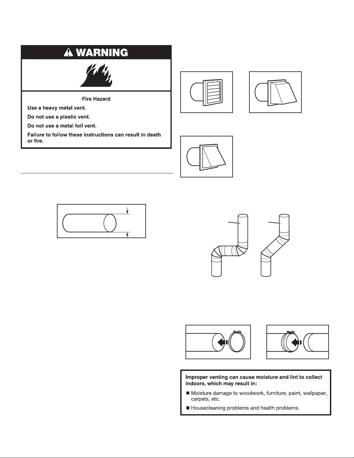
Exhaust hoods:
n Must be at least 12" (305 mm) from ground or any object that
may obstruct exhaust (such as owers, rocks, bushes, or
snow).
Recommended Styles:
Louvered hood Box hood
Acceptable Style:
Angled hood
Elbows:
n 45° elbows provide better airow than 90° elbows.
4"
(102 mm)
4" (102 mm) heavy metal exhaust vent
n Only a 4" (102 mm) heavy metal exhaust vent and clamps may
be used.
n Do not use plastic or metal foil vent.
Rigid metal vent:
n Recommended for best drying performance and to avoid
crushing and kinking.
Flexible metal vent: (Acceptable only if accessible to clean)
n Must be fully extended and supported in nal dryer location.
n Remove excess to avoid sagging and kinking that may result
in reduced airow and poor performance.
n Do not install in enclosed walls, ceilings, or oors.
n The total length should not exceed 7
NOTE: If using an existing vent system, clean lint from entire
length of the system and make sure exhaust hood is not
plugged with lint. Replace plastic or metal foil vents with rigid
metal or exible metal vents. Review “Vent System Chart” and,
if necessary, modify existing vent system to achieve best drying
performance.
3
/4 ft. (2.4 m).
Good
Better
Clamps:
n Use clamps to seal all joints.
n Exhaust vent must not be connected or secured with screws
or other fastening devices that extend into interior of duct
and catch lint. Do not use duct tape.
26
See “Venting Kits” for more information.
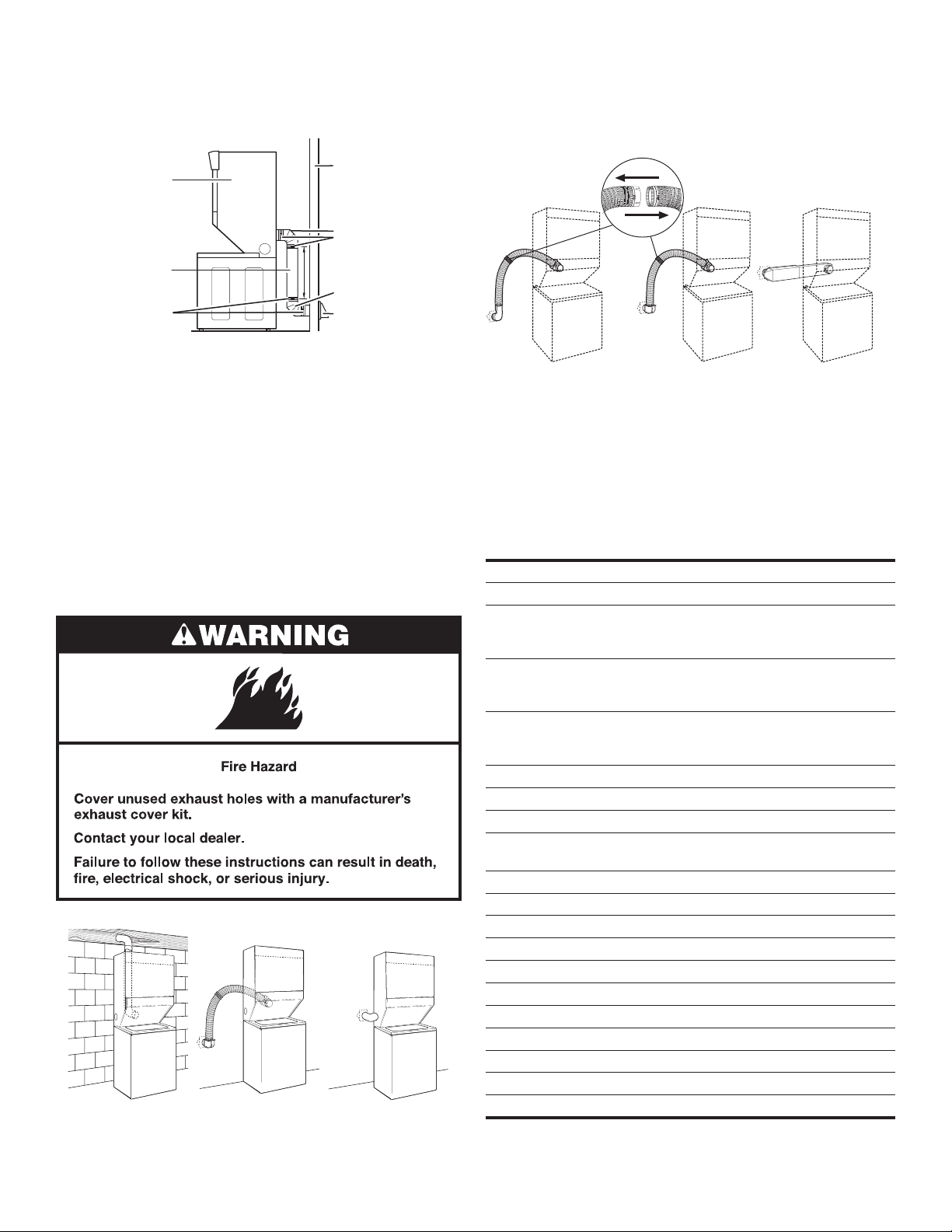
Plan Vent System
AB
C
Recommended exhaust installations
Typical installations vent the washer/dryer from the rear. Other
installations are possible.
A
B
C
D
E
F
G
H
Alternate installations for close clearances
Venting systems come in many varieties. Select the type best
for your installation. Three close-clearance installations are
shown. Refer to the manufacturer’s instructions.
A. Dryer
B. Rigid metal or exible metal vent
C. Clamps
D. Wall
E. Elbow
F. Clamps
G. Elbow
H. Exhaust hood
Optional exhaust installations:
This washer/dryer can be converted to exhaust out the right or
left side. To convert the washer/dryer, use Side Exhaust Kit Part
Number 279823. If your washer/dryer was previously exhausted
from the right or left side, it can be converted to rear exhaust by
using standard offset connections. To cover the hole in the side,
one of the following plugs can be added:
692790 (white)
3977784 (biscuit)
Follow the instructions in the kit to install. Kits are available from
the dealer from whom you purchased your washer/dryer.
ABC
A. Loop system with standard elbows
B. Loop system with one offset and one standard elbow
C. Vent system with one periscope (2" [51 mm] clearance)
NOTE: The following kits for close-clearance alternate
installations are available for purchase.
Venting Kits
For more information, call 1-866-698-2538, or visit us
at www.whirlpool.com/accessories. In Canada, call
1-800-688-2002 or visit us at www.whirlpoolparts.ca.
Part Number Descriptions
4396028 Over-the-Top Installation
4396037 0" (0 mm) to 18" (457 mm)
4396011 18" (457 mm) to 29" (737 mm)
4396014 29" (737 mm) to 50" (1.27 m)
4392892 In-wall metal DuraVent
279818 4-way vent kit – white
W10186596 4-way vent kit – universal grey
4396028 Sure Connect
4396009RP 5' Universal connect vent, exible dryer venting
4396010RP 6' SecureConnect
4396013RB Dryer vent installer’s kit
4396033RP 5' exible dryer venting with clamps
4396727RP 8' exible dryer venting with clamps
4396004 Dryer offset elbow
4396005 Wall offset elbow
4396006RW DuraSafe
4396007RW Through-the-wall vent cap
4396008RP 4" steel dryer venting clamps – 2 pack
8212662 Flush mounting louvered vent hood 4"
Metal vent periscope (For use with dryer vent
to wall vent mismatch)
Metal vent periscope (For use with dryer vent
to wall vent mismatch)
Metal vent periscope (For use with dryer vent
to wall vent mismatch)
™
periscope
™
venting kit
(over-the-top installation)
™
vent, exible dryer venting
™
close elbow
A. Standard rear offset exhaust installation
B. Rear exhaust for offset close-clearance connection
C. Left- or right-side exhaust installation
27
 Loading...