

Whirlpool WET3300SQ2, MET3800TW2 Installation Guide
27"(69CM)ELECTRIC WASHER RYER
INSTALLATIONINSTRUCTIONS
INSTRUCTIONSD'INSTALLATION
# #
IAVEUSE/SECt USE E C I IQUE DE 27"(69CM)
Table ofContents/Table des matii_res
WASHER/DRYER SAFETY ............................. 1
iNSTALLATiON iNSTRUCTiONS ................... 2
Tools and Parts ............................................. 2
Alternate Parts ............................................... 2
Location Requirements ................................. 3
Drain System ................................................. 4
Electrical Requirements - U.S.A ................... 4
Electrical Requirements - Canada ................ 5
Electrical Connection - U.S.A. Only .............. 6
Venting Requirements ................................. 11
Remove Shipping Strap .............................. 12
Install Leveling Legs .................................... 12
Connect the Drain Hose .............................. 12
Connect the Inlet Hoses ............................. 13
Secure the Drain Hose ................................ 14
Plan Vent System ........................................ 14
Install Vent System ...................................... 15
Level Washer/Dryer ..................................... 15
Connect Vent .............................................. 15
Complete Installation .................................. 16
SC:CURIT_e DE LA LAVEUSE/SECHEUSE ... 17
INSTRUCTIONS D'INSTALLATION .............. 18
Outillage et pi_ces ....................................... 18
Autres pi_ces .............................................. 19
Exigences d'emplacement ........................ 19
Syst_me de vidange ................................... 20
Specifications _lectriques - Canada ........... 21
Exigences concernant I'_vacuation ............ 22
Enlever la sangle d'exp_dition .................... 23
Installation des pieds de nivellement .......... 24
Raccordement du tuyau de vidange .......... 24
Raccordement des tuyaux d'alimentation.. 24
Immobilisation du tuyau de vidange ........... 25
Planification du syst_me d'_vacuation ....... 26
Installation du syst_me d'_vacuation ......... 27
Nivellement de la laveuse/s_cheuse ........... 27
Raccordement du conduit d'_vacuation .... 28
Achever I'installation ................................... 28
WASHER RYER SAFETY
Your safety and the safety of others are very important.
We have provided many important safety messages in this manual and on your appliance. Always read and obey all safety
messages.
This is the safety alert symbol.
This symbol alerts you to potential hazards that can kilt or hurt you and others.
All safety messages will follow the safety alert symbol and either the word "DANGER" or "WARNING."
These words mean:
You can be killed or seriously injured if you don't immediately
follow instructions.
You can be killed or seriously injured if you don't follow
instructions.
All safety messages wilt tell you what the potential hazard is, tell you how to reduce the chance of injury, and tell you what can
happen if the instructions are not followed.
W10222378A
WARNING - "RiskofFire"
- Clothes dryer installation must be performed by a qualified installer.
- Install the clothes dryer according to the manufacturer's instructions and local codes.
- Do not instal( a clothes dryer with flexib(e plastic venting materials, if flexible metal
(foil type) duct is installed, it must be of a specific type identified by the appliance
manufacturer as suitable for use with clothes dryers. Flexible venting materials are
known to collapse, be easily crushed, and trap lint. These conditions will obstruct
clothes dryer airflow and increase the risk of fire.
- To reduce the risk of severe injury or death, follow all installation instructions.
- Save these instructions.
INSTALLATIONINSTRUCTIONS
Parts needed:
Check local codes, electrical supply and venting, and read "Electrical
Gather the required tools and parts before starting installation.Read
and follow the instructions provided with any tools listed here.
Parts needed for washer (not provided):
[] Inlet hoses [] Flat washers
To o_der:
[] Call the dealer from whom you purchased your washer/dryer.
[] Call the toll-free number listed on the cover of the Washer/
Dryer User instructions.
[] Visit the website listed on the cover of the Washer/Dryer
User instructions.
NOTE: Replace inlet hoses after 5 years of use to reduce the risk
of hose failure. Record hose installation or replacement dates for
future reference.
Tools needed:
[] #2 Phillips and flat-blade [] Level
screwdriver
[] Adjustable wrench that
opens to 1" (25 mm) or 9_6" [] Ruler or measuring tape
open-end wrench (for [] Knife
adjusting washer/dryer feet) [] Vent clamps
[] 1¼.nut driver or socket
wrench (recommended) [] Pliers
[] Wire stripper (for U.S. [] Scissors
only, direct wire [] Tin snips (for new vent
installations) installations)
[] Caulking gun and
compound (for installing
new exhaust vent)
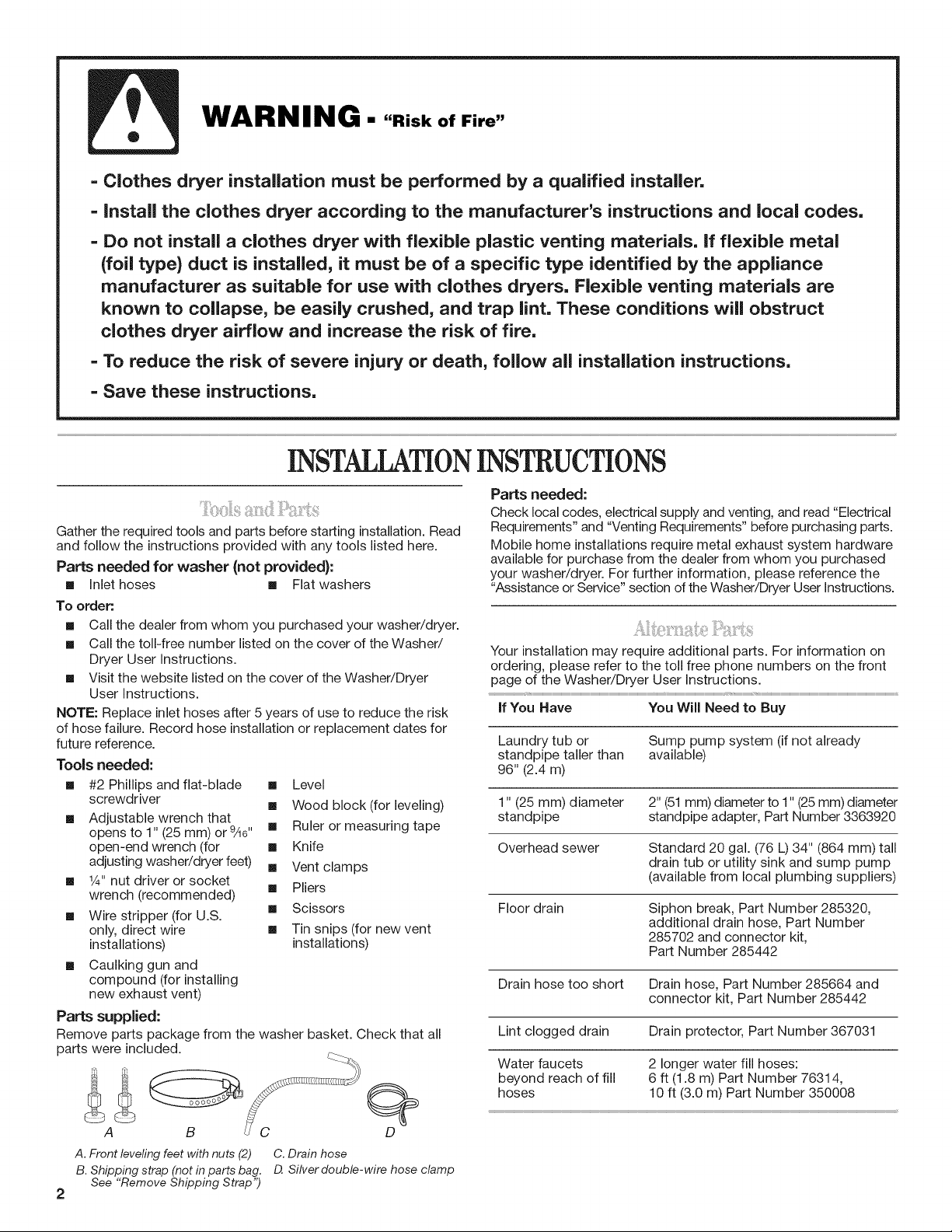
Parts supplied:
Remove parts package from the washer basket. Check that all
parts were included.
[] Wood block (for leveling)
Requirements" and "Venting Requirements" before purchasing parts.
Mobile home installations require metal exhaust system hardware
available for purchase from the dealer from whom you purchased
your washer/dryer. For further information, please reference the
"Assistance or Service" section of the Washer/Dryer User instructions.
Your installation may require additional parts. For information on
ordering, please refer to the toll free phone numbers on the front
page of the Washer/Dryer User Instructions.
if You Have You Will Need to Buy
Laundry tub or Sump pump system (if not already
standpipe taller than available)
96" (2.4 m)
1" (25 mm) diameter 2" (51mm) diameter to 1" (25mm) diameter
standpipe standpipe adapter, Part Number 3363920
Overhead sewer Standard 20 gal. (76 L) 34" (864 mm) tall
drain tub or utility sink and sump pump
(available from local plumbing suppliers)
Floor drain Siphon break, Part Number 285320,
additional drain hose, Part Number
285702 and connector kit,
Part Number 285442
Drain hose too short Drain hose, Part Number 285664 and
connector kit, Part Number 285442
Lint clogged drain Drain protector, Part Number 367031
Water faucets 2 longer water fill hoses:
beyond reach of fill 6 ft (1.8 m) Part Number 76314,
hoses 10 ft (3.0 m) Part Number 350008
A B _C D
A. Front leveling feet with nuts (2) C. Drain hose
B. Shipping strap (not in parts bag. D Silver double-wire hose clamp
See "Remove Shipping Strap")
2
Explosion Hazard
Keep flammable materials and vapors, such as
gasoline, away from dryer.
FaiJure to do so can result in death, explosion, or fire.
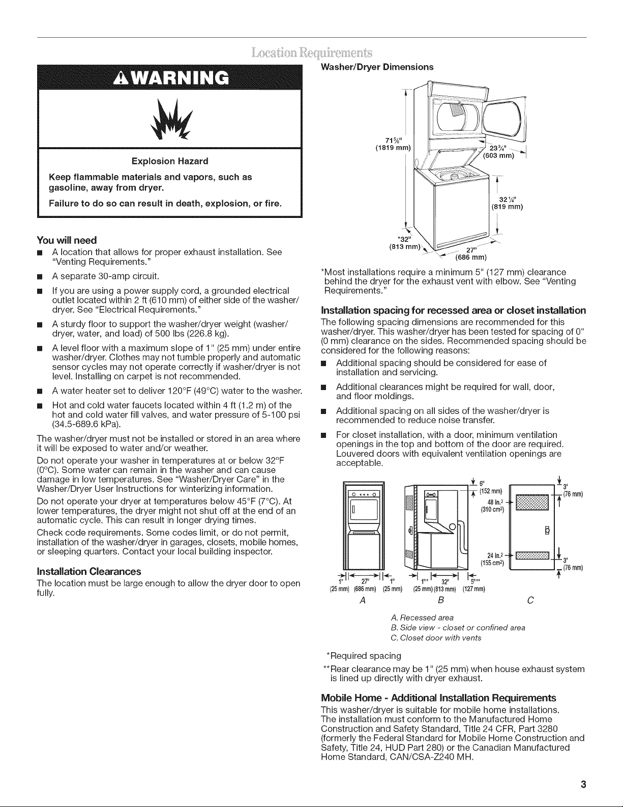
Washer/Dryer Dimensions
71%"
(1819 mm)
You will need
[] A location that allows for proper exhaust installation. See
"Venting Requirements."
[]
A separate 30-amp circuit.
[]
If you are using a power supply cord, a grounded electrical
outlet located within 2 ft (610 mm) of either side of the washer/
dryer. See "Electrical Requirements."
[]
A sturdy floor to support the washer/dryer weight (washer/
dryer, water, and load) of 500 Ibs (226.8 kg).
[]
A level floor with a maximum slope of 1" (25 mm) under entire
washer/dryer. Clothes may not tumble properly and automatic
sensor cycles may not operate correctly if washer/dryer is not
level. Installing on carpet is not recommended.
[]
A water heater set to deliver 120°F (49°C) water to the washer.
[]
Hot and cold water faucets located within 4 ft (1.2 m) of the
hot and cold water fill valves, and water pressure of 5-100 psi
(34.5-689.6 kPa).
The washer/dryer must not be installed or stored in an area where
it will be exposed to water and/or weather.
Do not operate your washer in temperatures at or below 32°F
(0°C). Some water can remain in the washer and can cause
damage in low temperatures. See "Washer/Dryer Care" in the
Washer/Dryer User Instructions for winterizing information.
Do not operate your dryer at temperatures below 45°F (7°C). At
lower temperatures, the dryer might not shut off at the end of an
automatic cycle. This can result in longer drying times.
Check code requirements. Some codes limit, or do not permit,
installation of the washer/dryer in garages, closets, mobile homes,
or sleeping quarters. Contact your local building inspector.
Installation Clearances
The location must be large enough to allow the dryer door to open
fully.
27"
(686 mm)
*Most installations require a minimum 5" (127 mm) clearance
behind the dryer for the exhaust vent with elbow. See "Venting
Requirements."
Installation spacing for recessed area or closet installation
The following spacing dimensions are recommended for this
washer/dryer. This washer/dryer has been tested for spacing of 0"
(0 mm) clearance on the sides. Recommended spacing should be
considered for the following reasons:
[] Additional spacing should be considered for ease of
installation and servicing.
[]
Additional clearances might be required for wall, door,
and floor moldings.
[]
Additional spacing on all sides of the washer/dryer is
recommended to reduce noise transfer.
[]
For closet installation, with a door, minimum ventilation
openings in the top and bottom of the door are required.
Louvered doors with equivalent ventilation openings are
acceptable.
OoooO
I1 I
I1 II
_6"
(152inn])
48 il. 2-
(310cn]2)
J 31_
-_(76 rnm)
1
|
(76n]m)
m
_i 27' il 1"
(25rnm) (686 inn]) (25 mn])
A
A. Recessed area
B. Side view - closet or confined area
C. Closet door with vents
÷1 31"_Z;-_2,,I
1"*
(25mn])(813n]rn)(127 mm)
B C
24in.2- 2[ 3"
(155cm2)
5"**
*Required spacing
**Rear clearance may be 1" (25 mm) when house exhaust system
is lined up directly with dryer exhaust.
Mobile Home = Additional installation Requirements
This washer/dryer is suitable for mobile home installations.
The installation must conform to the Manufactured Home
Construction and Safety Standard, Title 24 CFR, Part 3280
(formerly the Federal Standard for Mobile Home Construction and
Safety, Title 24, HUD Part 280) or the Canadian Manufactured
Home Standard, CAN/CSA-Z240 MH.
MobiNe home installations require:
[] Metal exhaust system hardware, which is available for
purchase from your dealer.
[]
Special provisions must be made in mobile homes to
introduce outside air into the dryer. The opening (such as a
nearby window) should be at least twice as large as the dryer
exhaust opening.
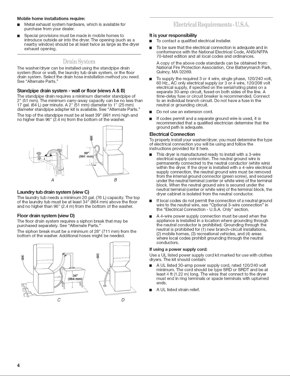
The washer/dryer can be installed using the standpipe drain
system (floor or wall), the laundry tub drain system, or the floor
drain system. Select the drain hose installation method you need.
See "Alternate Parts."
Standpipe drain system =wall or floor {views A & B}
The standpipe drain requires a minimum diameter standpipe of
2" (51 mm). The minimum carry-away capacity can be no less than
17 gal. (64 L) per minute. A 2" (51 mm) diameter to 1" (25 mm)
diameter standpipe adapter kit is available. See "Alternate Parts."
The top of the standpipe must be at least 39" (991 mm) high and
no higher than 96" (2.4 m) from the bottom of the washer.
39 I_
(991 mm)
B
Laundry tub drain system {view C}
The laundry tub needs a minimum 20 gal. (76 L) capacity. The top
of the laundry tub must be at least 34" (864 mm) above the floor
and no higher than 96" (2.4 m) from the bottom of the washer.
Floor drain system {view D)
The floor drain system requires a siphon break that may be
purchased separately. See "Alternate Parts."
The siphon break must be a minimum of 28" (711 mm) from the
bottom of the washer. Additional hoses might be needed.
It is your responsibility
[] Tocontact a qualified electrical installer.
[] To be sure that the electrical connection is adequate and in
conformance with the National Electrical Code, ANSl/NFPA
70-latest edition and all local codes and ordinances.
A copy of the above code standards can be obtained from:
National Fire Protection Association, One Batterymarch Park,
Quincy, MA 02269.
To supply the required 3 or 4 wire, single phase, 120/240 volt,
60 Hz., AC only electrical supply (or 3 or 4 wire, 120/208 volt
electrical supply, if specified on the serial/rating plate) on a
separate 30-amp circuit, fused on both sides of the line. A
time-delay fuse or circuit breaker is recommended. Connect
to an individual branch circuit. Do not have a fuse in the
neutral or grounding circuit.
[] Do not use an extension cord.
[] If codes permit and a separate ground wire is used, it is
recommended that a qualified electrician determine that the
ground path is adequate.
Electrical Connection
To properly install your washer/dryer, you must determine the type
of electrical connection you will be using and follow the
instructions provided for it here.
[] This dryer is manufactured ready to install with a 3-wire
electrical supply connection. The neutral ground wire is
permanently connected to the neutral conductor (white wire)
within the dryer. If the dryer is installed with a 4-wire electrical
supply connection, the neutral ground wire must be removed
from the internal ground connector (green screw), and secured
under the neutral terminal (center or white wire) of the terminal
block. When the neutral ground wire is secured under the
neutral terminal (center or white wire) of the terminal block, the
dryer cabinet is isolated from the neutral conductor.
If local codes do not permit the connection of a neutral ground
wire to the neutral wire, see "Optional 3-wire connection" in
the "Electrical Connection - U.S.A. Only" section.
A 4-wire power supply connection must be used when the
appliance is installed in a location where grounding through
the neutral conductor is prohibited. Grounding through the
neutral is prohibited for (1) new branch-circuit installations,
(2) mobile homes, (3) recreational vehicles, and (4) areas
where local codes prohibit grounding through the neutral
conductors.
If using a power supply cord:
Use a UL listed power supply cord kit marked for use with clothes
dryers. The kit should contain:
[] A UL listed 30-amp power supply cord, rated 120/240 volt
minimum. The cord should be type SRD or SRDT and be at
least 4 ft (1.22 m) long. The wires that connect to the dryer
must end in ring terminals or spade terminals with upturned
ends.
[] A UL listed strain relief.
C D
4
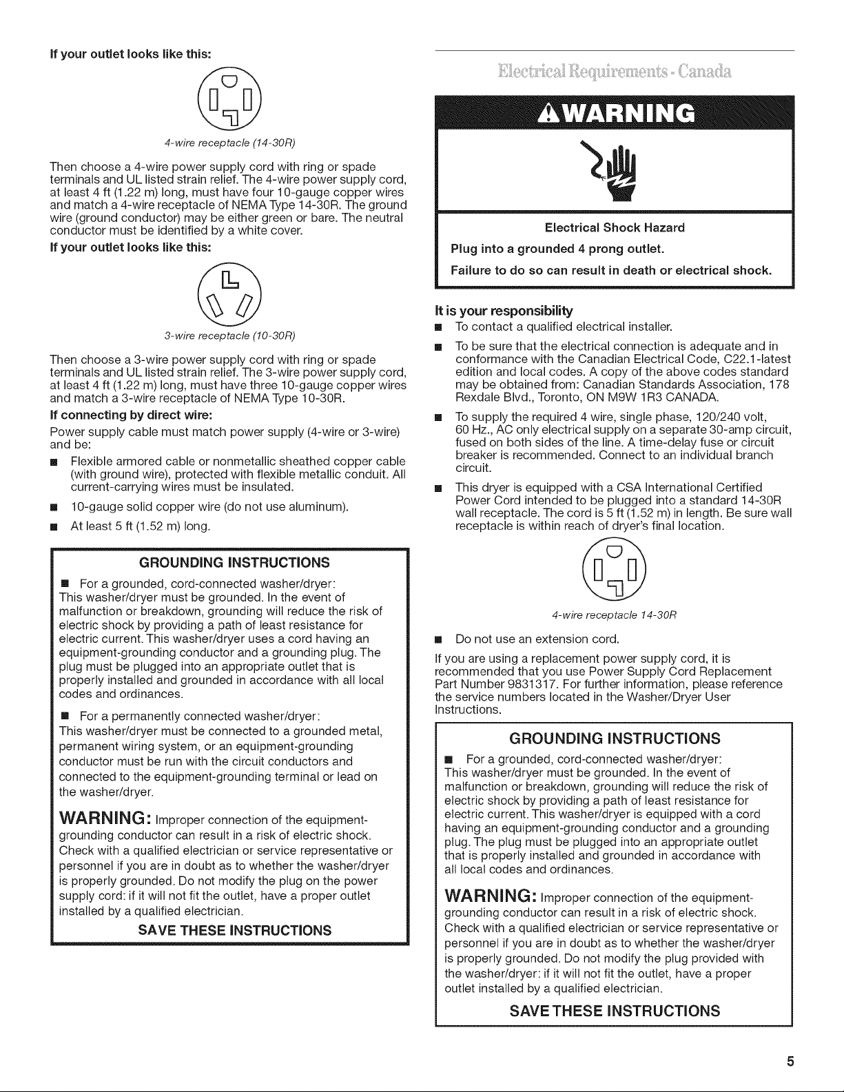
if your outlet looks like this:
4-wire receptacle (14-30R)
Then choose a 4-wire power supply cord with ring or spade
terminals and UL listed strain relief. The 4-wire power supply cord,
at least 4 ft (1.22 m) long, must have four 10-gauge copper wires
and match a 4-wire receptacle of NEMA Type 14-30R. The ground
wire (ground conductor) may be either green or bare. The neutral
conductor must be identified by a white cover.
If your outlet looks like this:
3-wire receptacle (10-30R)
Then choose a 3-wire power supply cord with ring or spade
terminals and UL listed strain relief. The 3-wire power supply cord,
at least 4 ft (1.22 m) long, must have three 10-gauge copper wires
and match a 3-wire receptacle of NEMA Type 10-30R.
If connecting by direct wire:
Power supply cable must match power supply (4-wire or 3-wire)
and be:
[] Flexible armored cable or nonmetallic sheathed copper cable
(with ground wire), protected with flexible metallic conduit. All
current-carrying wires must be insulated.
[] 10-gauge solid copper wire (do not use aluminum).
[] At least 5 ft (1.52 m) long.
Electrical Shock Hazard
Plug into a grounded 4 prong outlet.
Failure to do so can result in death or electrical shock.
it is your responsibility
[] Tocontact a qualified electrical installer.
To be sure that the electrical connection is adequate and in
conformance with the Canadian Electrical Code, C22.1-1atest
edition and local codes. A copy of the above codes standard
may be obtained from: Canadian Standards Association, 178
Rexdale Blvd., Toronto, ON M9W 1R3 CANADA.
To supply the required 4 wire, single phase, 120/240 volt,
60 Hz., AC only electrical supply on a separate 30-amp circuit,
fused on both sides of the line. A time-delay fuse or circuit
breaker is recommended. Connect to an individual branch
circuit.
This dryer is equipped with a CSA International Certified
Power Cord intended to be plugged into a standard 14-30R
wall receptacle. The cord is 5 ft (1.52 m) in length. Be sure wall
receptacle is within reach of dryer's final location.
GROUNDING INSTRUCTIONS
[] For a grounded, cord-connected washer/dryer:
This washer/dryer must be grounded. In the event of
malfunction or breakdown, grounding will reduce the risk of
electric shock by providing a path of least resistance for
electric current. This washer/dryer uses a cord having an
equipment-grounding conductor and a grounding plug. The
plug must be plugged into an appropriate outlet that is
properly installed and grounded in accordance with all local
codes and ordinances.
[] For a permanently connected washer/dryer:
This washer/dryer must be connected to a grounded metal,
permanent wiring system, or an equipment-grounding
conductor must be run with the circuit conductors and
connected to the equipment-grounding terminal or lead on
the washer/dryer.
WARNING: Improper connection of the equipment-
grounding conductor can result in a risk of electric shock.
Check with a qualified electrician or service representative or
personnel if you are in doubt as to whether the washer/dryer
is properly grounded. Do not modify the plug on the power
supply cord: if it wilt not fit the outlet, have a proper outlet
installed by a qualified electrician.
SAVE THESE INSTRUCTIONS
4-wire receptacle 14-30R
[] Do not use an extension cord.
If you are using a replacement power supply cord, it is
recommended that you use Power Supply Cord Replacement
Part Number 9831317. For further information, please reference
the service numbers located in the Washer/Dryer User
Instructions.
GROUNDING iNSTRUCTiONS
[] For a grounded, cord-connected washer/dryer:
This washer/dryer must be grounded. In the event of
malfunction or breakdown, grounding will reduce the risk of
electric shock by providing a path of least resistance for
electric current. This washer/dryer is equipped with a cord
having an equipment-grounding conductor and a grounding
plug. The plug must be plugged into an appropriate outlet
that is properly installed and grounded in accordance with
all local codes and ordinances.
WARNING" Improper connection of the equipment-
grounding conductor can result in a risk of electric shock.
Check with a qualified electrician or service representative or
personnel if you are in doubt as to whether the washer/dryer
is properly grounded. Do not modify the plug provided with
the washer/dryer: if it will not fit the outlet, have a proper
outlet installed by a qualified electrician.
SAVE THESE INSTRUCTIONS
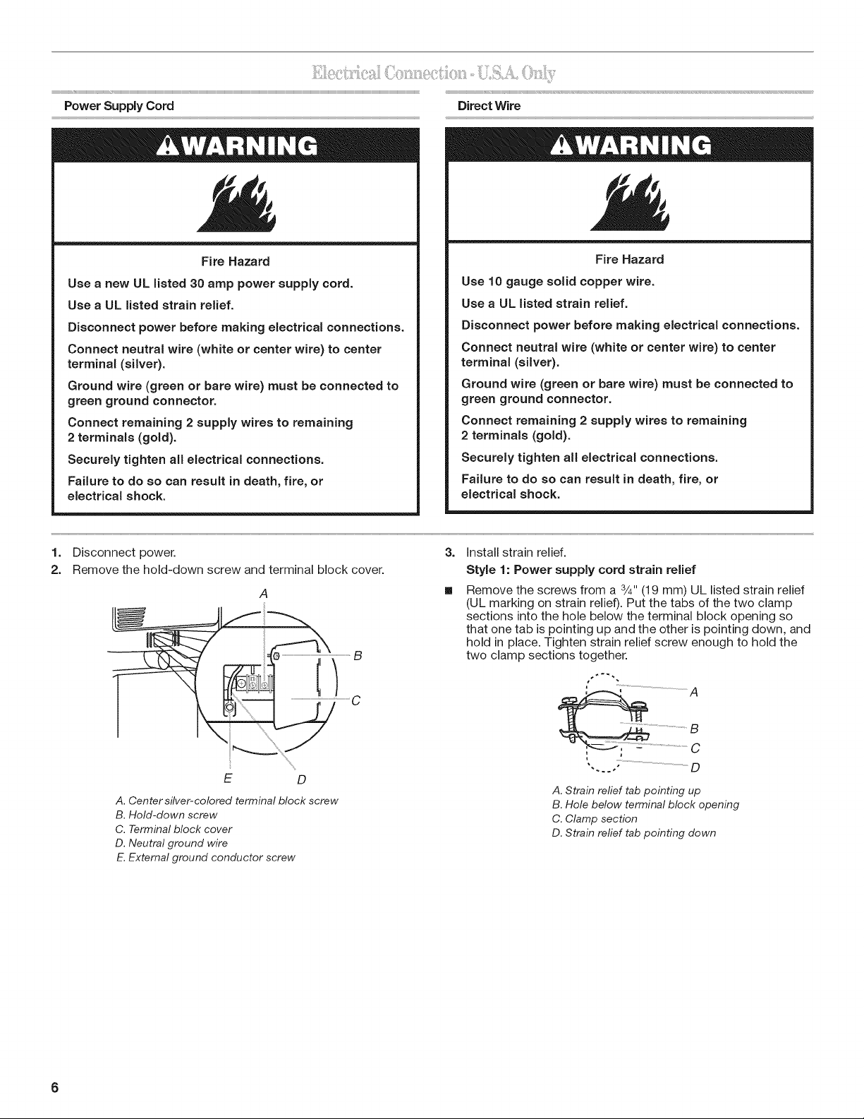
Power Supply Cord
Direct Wire
Fire Hazard
Use a new UL listed 30 amp power supply cord.
Use a UL listed strain relief.
Disconnect power before making electrical connections.
Connect neutral wire (white or center wire) to center
terminal (silver).
Ground wire (green or bare wire) must be connected to
green ground connector.
Connect remaining 2 supply wires to remaining
2 terminals (gold).
Securely tighten all electrical connections.
Failure to do so can result in death, fire, or
electrical shock.
1. Disconnect power.
2. Remove the hold-down screw and terminal block cover.
A
Fire Hazard
Use 10 gauge solid copper wire.
Use a UL listed strain relief.
Disconnect power before making electrical connections.
Connect neutral wire (white or center wire) to center
terminal (silver).
Ground wire (green or bare wire) must be connected to
green ground connector.
Connect remaining 2 supply wires to remaining
2 terminals (gold).
Securely tighten all electrical connections.
Failure to do so can result in death, fire, or
electrical shock.
3. Install strain relief.
Style 1: Power supply cord strain relief
Remove the screws from a 3/4"(19 mm) UL listed strain relief
(UL marking on strain relief). Put the tabs of the two clamp
sections into the hole below the terminal block opening so
that one tab is pointing up and the other is pointing down, and
hold in place. Tighten strain relief screw enough to hold the
two clamp sections together.
E D
A. Center silver-colored terminal block screw
B. Hold-down screw
C. Terminal block cover
D. Neutral ground wire
E.External ground conductor screw
', .... "..................................D
A. Strain refief tab pointing up
B. Hole below terminal block opening
C. Clamp section
D. Strain refief tab pointing down
6
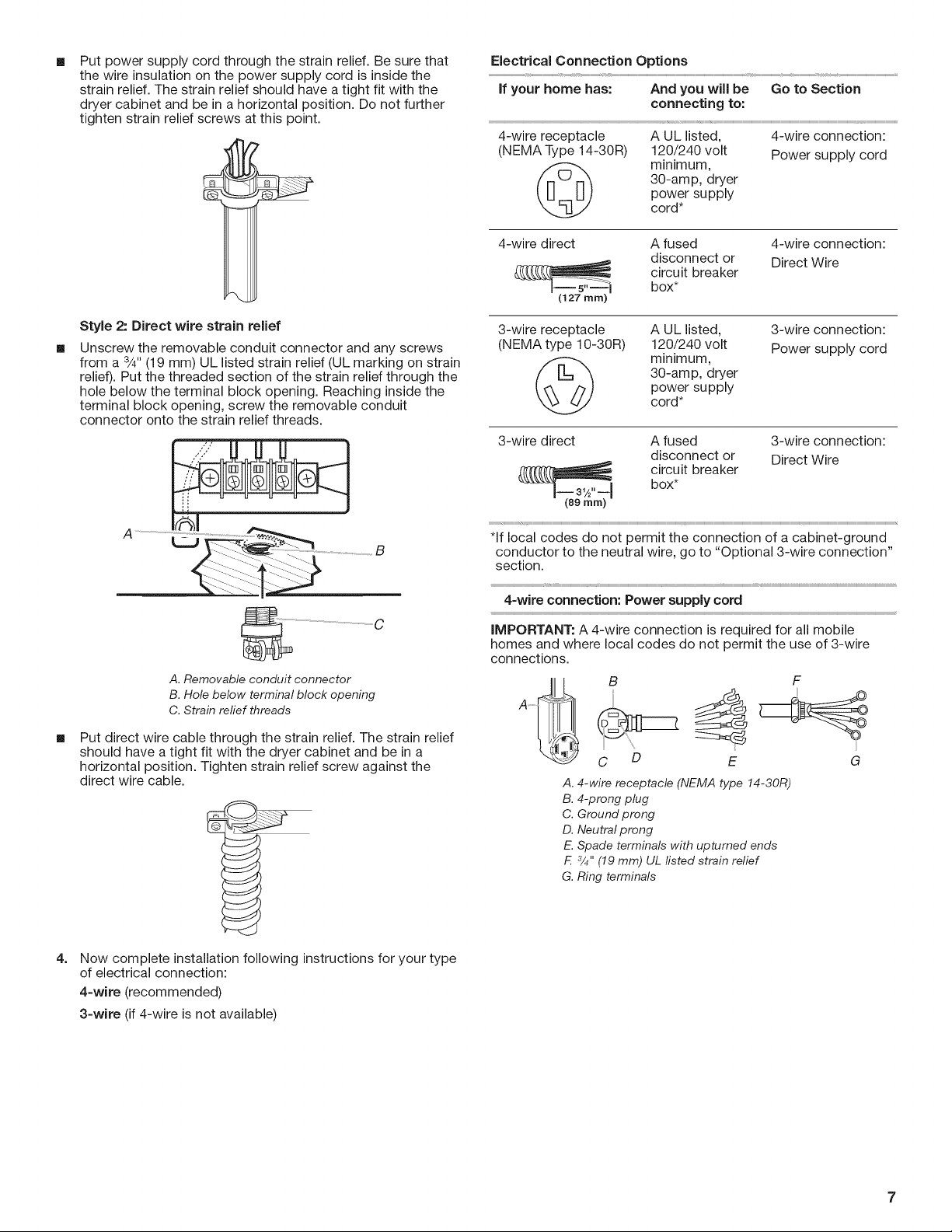
[]
Put power supply cord through the strain relief. Be sure that
the wire insulation on the power supply cord is inside the
strain relief. The strain relief should have a tight fit with the
dryer cabinet and be in a horizontal position. Do not further
tighten strain relief screws at this point.
Electrical Connection Options
If your home has: And you will be
Go to Section
connecting to:
4-wire receptacle A UL listed, 4-wire connection:
(NEMA Type 14-30R) 120/240 volt Power supply cord
30-amp, dryer
(_ minimum,
power supply
cord*
4-wire direct A fused 4-wire connection:
disconnect or Direct Wire
circuit breaker
(127 ram)
box*
Style 2: Direct wire strain relief
[]
Unscrew the removable conduit connector and any screws
from a 3/4"(19 mm) UL listed strain relief (UL marking on strain
relief). Put the threaded section of the strain relief through the
hole below the terminal block opening. Reaching inside the
terminal block opening, screw the removable conduit
connector onto the strain relief threads.
.......g
.......................... C
A. Removable conduit connector
B. Hole below terminal block opening
C. Strainrelief threads
[]
Put direct wire cable through the strain relief. The strain relief
should have a tight fit with the dryer cabinet and be in a
horizontal position. Tighten strain relief screw against the
direct wire cable.
3-wire receptacle A UL listed,
(NEMA type 10-30R) 120/240 volt
3-wire connection:
Power supply cord
30-amp, dryer
_j_ minimum,
power supply
cord*
3-wire direct A fused 3-wire connection:
disconnect or Direct Wire
box*
circuit breaker
(89 mm_
*If local codes do not permit the connection of a cabinet-ground
conductor to the neutral wire, go to "Optional 3-wire connection"
section.
4-wire connection: Power supply cord
IMPORTANT: A 4-wire connection is required for all mobile
homes and where local codes do not permit the use of 3-wire
connections.
C D E G
A. 4-wire receptacle (NEMA type 14-30R)
B. 4-prong plug
C. Ground prong
D. Neutral prong
E. Spade terminals with upturned ends
F. 3/4"(19 mm) UL fisted strain relief
G. Ring terminals
4=
Now complete installation following instructions for your type
of electrical connection:
4-wire (recommended)
3-wire (if 4-wire is not available)
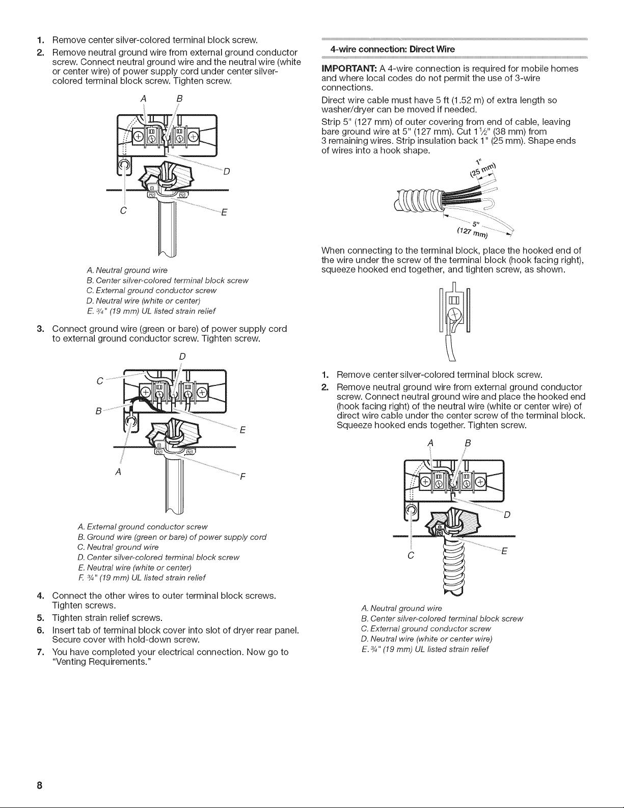
1.
Remove center silver-colored terminal block screw.
2.
Remove neutral ground wire from external ground conductor
screw. Connect neutral ground wire and the neutral wire (white
or center wire) of power supply cord under center silver-
colored terminal block screw. Tighten screw.
A B
A. Neutral ground wire
B. Center silver-colored terminal block screw
C. External ground conductor screw
D. Neutral wire (white or center)
E. 3/4"(19 mm) UL listed strain relief
3.
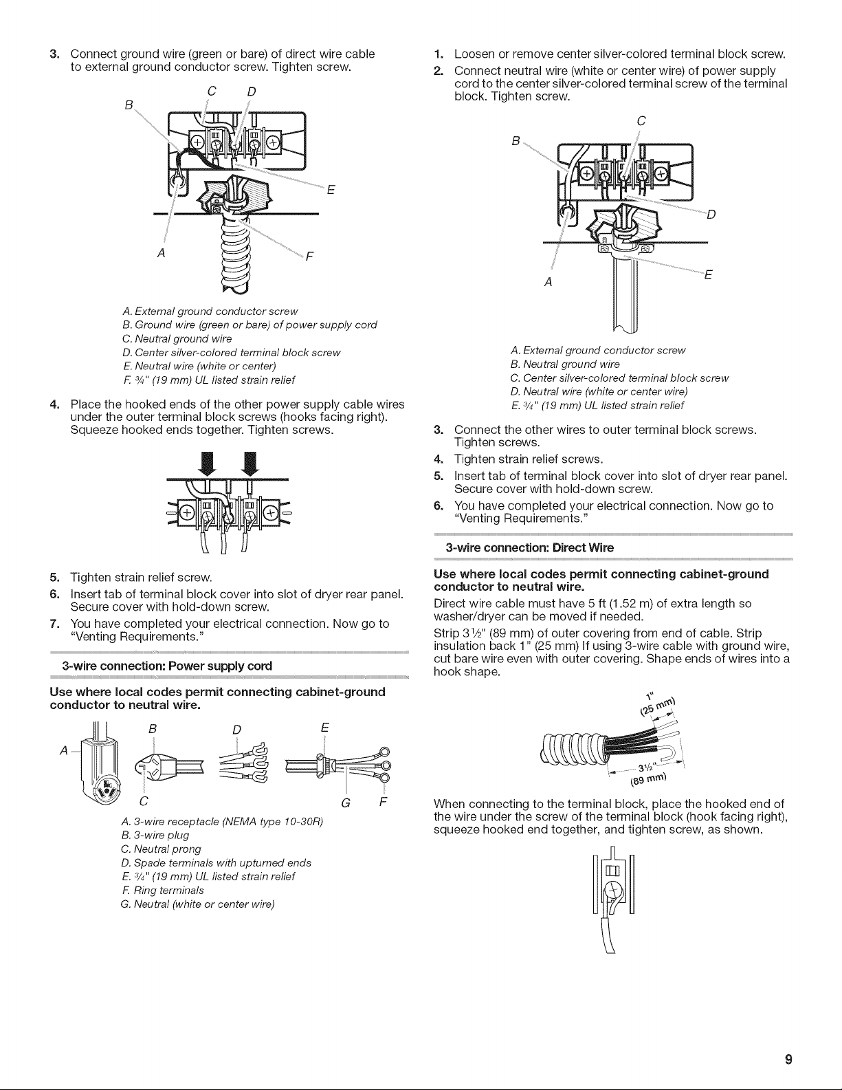
Connect ground wire (green or bare) of power supply cord
to external ground conductor screw. Tighten screw.
D
[
C
E
4-wire connection: Direct Wire
iMPORTANT: A 4-wire connection is required for mobile homes
and where local codes do not permit the use of 3-wire
connections.
Direct wire cable must have 5 ft (1.52 m) of extra length so
washer/dryer can be moved if needed.
Strip 5" (127 mm) of outer covering from end of cable, leaving
bare ground wire at 5" (127 mm). Cut 11/2"(38 mm) from
3 remaining wires. Strip insulation back 1" (25 mm). Shape ends
of wires into a hook shape.
When connecting to the terminal block, place the hooked end of
the wire under the screw of the terminal block (hook facing right),
squeeze hooked end together, and tighten screw, as shown.
1.
Remove center silver-colored terminal block screw.
2.
Remove neutral ground wire from external ground conductor
screw. Connect neutral ground wire and place the hooked end
(hook facing right) of the neutral wire (white or center wire) of
direct wire cable under the center screw of the terminal block.
Squeeze hooked ends together. Tighten screw.
A B
S'
S_
A
A. External ground conductor screw
B. Ground wire (green or bare) of power supply cord
C. Neutral ground wire
D. Center silver-colored terminal block screw
E. Neutral wire (white or center)
E 3/4"(19 mm) UL listed strain relief
....F
4. Connect the other wires to outer terminal block screws.
Tighten screws.
5. Tighten strain relief screws.
6. Insert tab of terminal block cover into slot of dryer rear panel.
Secure cover with hold-down screw.
7. You have completed your electrical connection. Now go to
"Venting Requirements."
C 1 ...........................................................E
A. Neutral ground wire
B. Center silver-colored terminal block screw
C. External ground conductor screw
D. Neutral wire (white or center wire)
E. 3/4,,(19 mm) UL fisted strain relief
8
3.
Connect ground wire (green or bare) of direct wire cable
to external ground conductor screw. Tighten screw.
E
F
A. External ground conductor screw
B. Ground wire (green or bare) of power supply cord
C. Neutral ground wire
D. Center silver-colored terminal block screw
E. Neutral wire (white or center)
F. 3/4"(19 mm) UL listed strain refief
4.
Place the hooked ends of the other power supply cable wires
under the outer terminal block screws (hooks facing right).
Squeeze hooked ends together. Tighten screws.
1.
Loosen or remove center silver-colored terminal block screw.
2.
Connect neutral wire (white or center wire) of power supply
cord to the center silver-colored terminal screw of the terminal
block. Tighten screw.
A
A. External ground conductor screw
B. Neutral ground wire
C. Center silver-colored terminal block screw
D. Neutral wire (white or center wire)
E. 3/4"(19 mm) UL fisted strain relief
3. Connect the other wires to outer terminal block screws.
Tighten screws.
4. Tighten strain relief screws.
5. Insert tab of terminal block cover into slot of dryer rear panel.
Secure cover with hold-down screw.
6.
You have completed your electrical connection. Now go to
"Venting Requirements."
5. Tighten strain relief screw.
6. Insert tab of terminal block cover into slot of dryer rear panel.
Secure cover with hold-down screw.
7. You have completed your electrical connection. Now go to
"Venting Requirements."
3-wire connection: Power supply cord
Use where IocaJcodes permit connecting cabinet-ground
conductor to neutral wire.
D
C
A. 3-wire receptacle (NEMA type 10-30R)
B. 3-wire plug
C. Neutral prong
D. Spade terminals with upturned ends
E. 3/4"(19 mm) UL listed strain relief
F. Ring terminals
G. Neutral (white or center wire)
E
G F
3-wire connection: Direct Wire
Use where local codes permit connecting cabinet-ground
conductor to neutral wire.
Direct wire cable must have 5 ft (1.52 m) of extra length so
washer/dryer can be moved if needed.
Strip 31/2'' (89 mm) of outer covering from end of cable. Strip
insulation back 1" (25 mm) if using 3-wire cable with ground wire,
r
cut bare wire even with outer covering. Shape ends of wires into a
hook shape.
kktkkttttkL >:
,_..........3A .....
{s9_m_
When connecting to the terminal block, place the hooked end of
the wire under the screw of the terminal block (hook facing right),
squeeze hooked end together, and tighten screw, as shown.
 Loading...