

Whirlpool werp4120pq0 Installation Instructions Manual
Installation Instructions
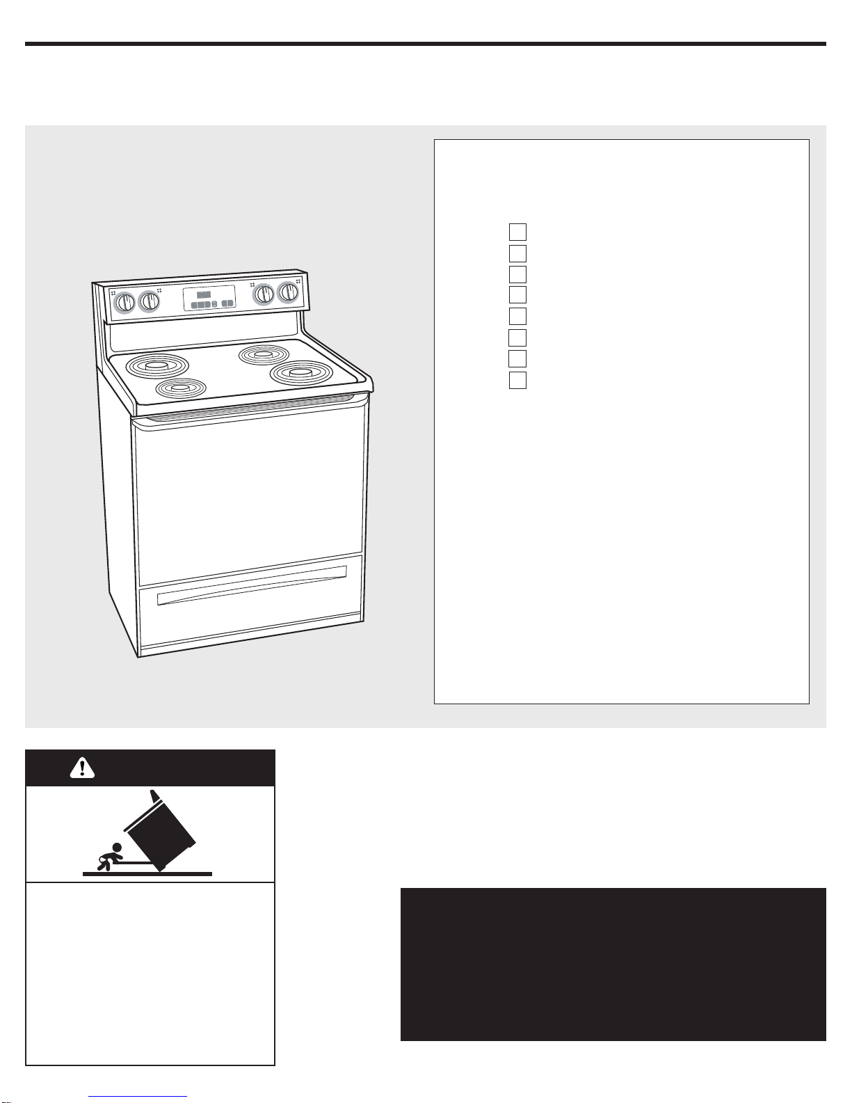
30" (76.2 cm) Electric
Freestanding Range
Quick Reference
Table of Contents:
Pages
2
3
3
4
5
6
6
6
If you need assistance:
Check your Use and Care Guide for a toll-free number to
call or call the dealer from whom you purchased this
appliance. The dealer is listed in the Yellow Pages of your
phone directory under “Appliances — Household —
Major — Service and Repair.”
Call when you:
Have questions about range installation or operation.
Need to obtain the name and number of an authorized
service company.
When you call, you will need:
The range model number.
The range serial number.
Both numbers are listed on the model/serial rating plate
located on the oven frame behind the storage drawer
panel.
Before you start
Product dimensions
Cabinet dimensions/requirements
Installation steps
Check operation
If range does not operate
If you need assistance/service
Moving the range
IMPORTANT:
Installer: Leave Installation Instructions with the homeowner.
Homeowner: Keep Installation Instructions for future reference.
Save Installation Instructions for local electrical inspector's use.
IMPORTANT:
Read and save these instructions.
Part No. 9756848
Tip Over Hazard
A child or adult can tip the range
and be killed.
Connect anti-tip bracket to rear
range foot.
Reconnect the anti-tip bracket, if
the range is moved.
Failure to follow these instructions
can result in death or serious
burns to children and adults.
WARNING
8 8 8
2
Before you start...
Mobile home installation
The installation of this range must
conform with the Manufactured Home
Construction and Safety Standard, Title
24 CFR, Part 3280 [formerly the Federal
Standard for Mobile Home Construction
and Safety, Title 24, HUD (Part 280)] or,
when such standard is not applicable, the
Standard for Manufactured Home
Installations, ANSI A225.1/NFPA 501A*,
or with local codes.
When this range is installed in a mobile
home, it must be secured to the floor
during transit. Any method of securing
the range is adequate as long as it
conforms to the standards listed above.
Four-wire power supply cord or cable
must be used in a mobile home
installation. The appliance wiring will
need to be revised.
Tools needed:
• level
• flat-blade screwdriver
• 3/8" drive ratchet
• 3/8" and 5/16" nut driver
• hand or electric drill
• channel lock pliers
• safety glasses
• gloves
• measuring tape or ruler
• wood floors: 1/8" drill bit
• concrete/ceramic floors: 3/16" carbide-tipped
masonry drill bit (Hammer may be needed
for anchors.)
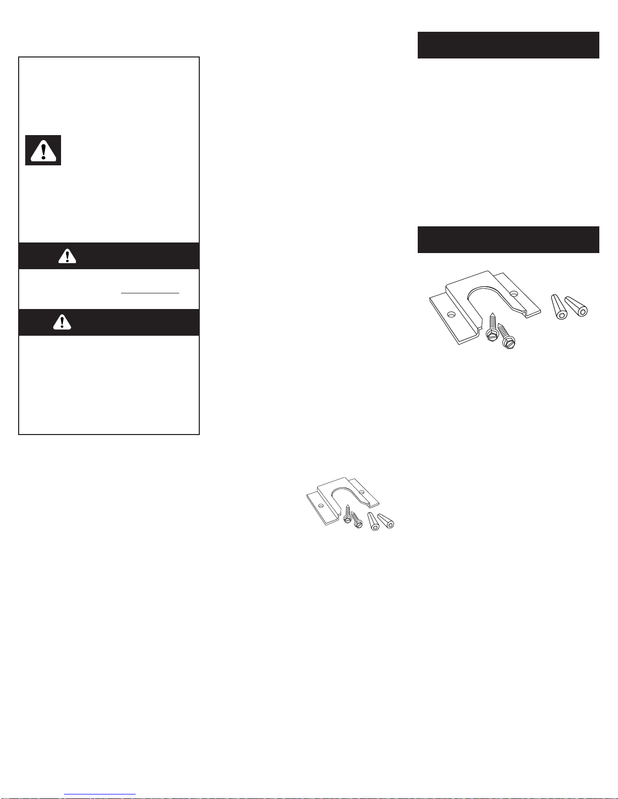
Parts supplied:
Bracket must be securely mounted to
sub-floor. Thickness of flooring may require longer
screws to anchor bracket to sub-floor. Longer
screws are available from your local hardware store.
Copies of the standards listed may be obtained
from:
* National Fire Protection Association
Batterymarch Park
Quincy, Massachusetts, 02269
** CSA International
8501 East Pleasant Valley Road
Cleveland, Ohio 44131-5575
The floor anti-tip
bracket MUST be
installed. To install
the anti-tip
bracket shipped
with the range, see Page 4 and the
anti-tip bracket template.
IMPORTANT: Observe all governing codes
and ordinances. Failure to meet codes
and ordinances could lead to fire or
electrical shock.
Proper installation is your responsibility.
A qualified technician must install this
range. Make sure you have everything
necessary for correct installation. It is the
installer’s responsibility to comply with
installation clearances specified on the
model/serial rating plate. The model/serial
rating plate is located on the oven frame
behind the storage drawer panel.
Check location where range will be
installed. The range should be located for
convenient use in kitchen.
When installing a range under existing
cabinets and the installation does not
meet the minimum cabinet clearances,
install a range hood above the cooktop to
avoid burn hazards.
All openings in the wall or floor where
range is to be installed must be sealed.
You can be killed or seriously
injured if you don’t follow
instructions.
DANGER
Your safety and the safety of
others are very important.
We have provided many important
safety messages in this manual and
on your appliance.Always read and
obey all safety messages.
All safety messages will tell you
what the potential hazard is, tell you
how to reduce the chance of injury,
and tell you what can happen if the
instructions are not followed.
You can be killed or seriously
injured if you don’t immediatel
y
follow instructions.
WARNING
This is the safety alert
symbol.
This symbol alerts you to
potential hazards that can kill or hurt
you and others.
All safety messages will follow the
safety alert symbol and either the
word “DANGER” or “WARNING”.
These words mean:
Cabinet opening dimensions that are
shown must be used. Given dimensions
are minimum clearances.
Grounded electrical outlet is required.
It is the customer’s responsibility:
To contact a qualified electrical installer.
To assure that the electrical installation is
adequate and in conformance with
National Electrical Code, ANSI/NFPA 70 –
latest edition*, or CSA Standard C22.1,
Canadian Electrical Code, Part 1 – latest
edition**, and all local codes and
ordinances.
2 plastic
anchors
floor-mounted
anti-tip bracket
2 screws
(#10 x 1-1/2")
Not shown:
literature pack
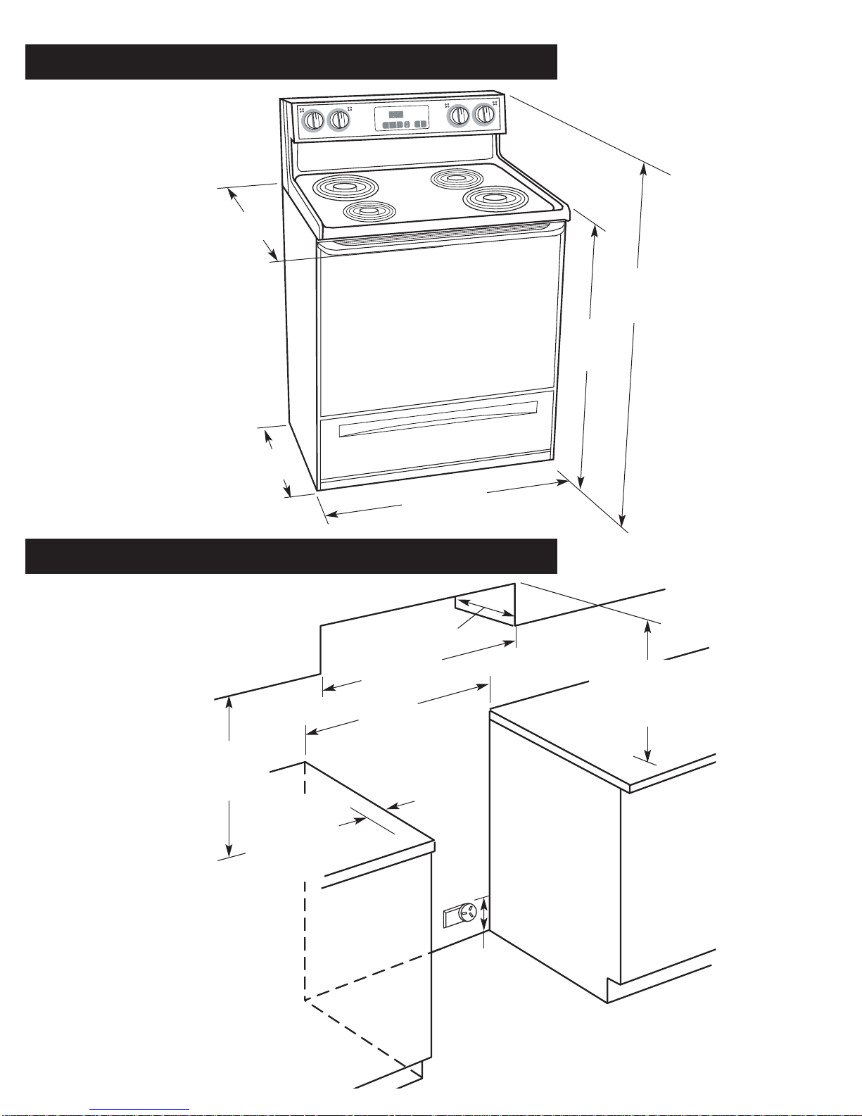
Wall receptacle —
8" (20.3 cm) to
22" (55.9 cm)
from either
cabinet
7" (17.8 cm)
max. from
floor
For minimum
clearance to the top
of the cooktop, see
NOTE.**
Do not pinch the power
supply cord between the
range and the wall.
Do not seal the range to
the side cabinets.
18" (45.7 cm)
min. clearance
upper cabinet to
countertop
13" (33 cm) max.
upper cabinet depth
opening width
31-1/8" (78.7 cm)
30" (76.2 cm) min.
cabinet opening width
4" (10.2 cm) min.
countertop space
to side wall or
other combustible
material
Product dimensions
Cabinet dimensions/requirements
3
**NOTE: 24" (61 cm) min. when bottom of
wood or metal cabinet is protected by not
less than 1/4" (0.64 cm) flame retardant
millboard covered with not less than No. 28
MSG sheet steel, 0.015" (0.4 mm) stainless
steel, 0.024" (0.6 mm) aluminum or 0.020"
(0.5 mm) copper.
30" min. (76.2 cm) clearance between the top
of the cooking platform and the bottom of an
unprotected wood or metal cabinet.
29-7/8" (75.9 cm)
width
27-1/8" (68.9 cm)
depth with handle
46-7/8"
(119.1 cm)
overall
height
24-13/16"
(63.0 cm)
36"
(91.4 cm)
cooktop
height
Cabinet opening dimensions
25" (63.5 cm) countertop depth,
24" (61.0 cm) base cabinet depth,
36" (91.4 cm) countertop height
8 8 8
Before moving range across floor, check
that range is still on cardboard shipping
base to protect floor covering.
5.
Move range close to cabinet
opening.
6.
Remove cardboard from under
range. Carefully move range into final
position.
Operating position
8.
If installing the range in a mobile
home, you must secure the range to the
floor. Any method of securing the range
is adequate as long as it conforms to the
standards in the “Mobile home
installation” instruction section.
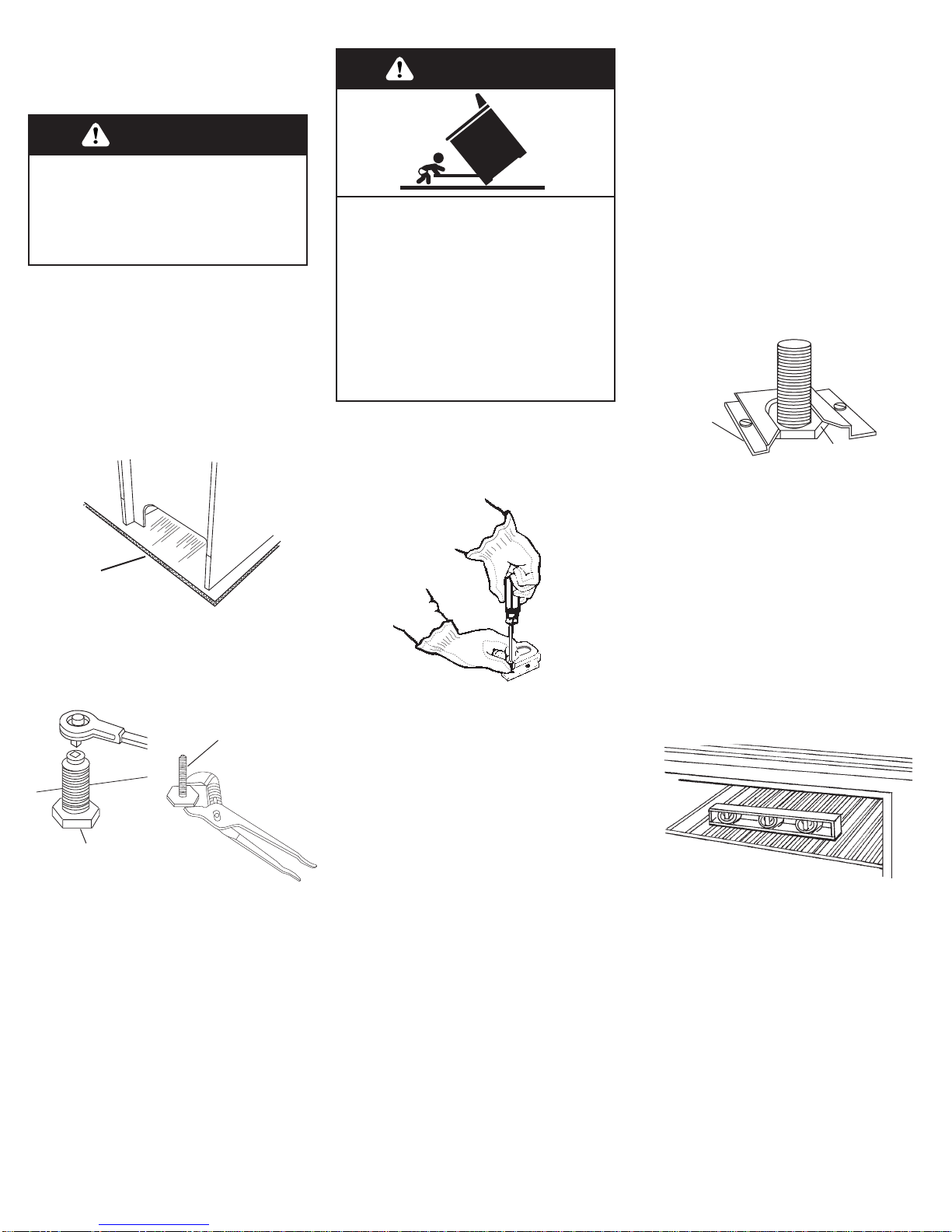
9.
Place rack in oven. Place level on
rack, first side to side; then front to back.
If range is not level, pull range forward
until rear leveling leg is removed from
the anti-tip bracket. Use 3/8" drive ratchet
and channel lock pliers to adjust leveling
legs up or down until range is level. Push
range back into position. Check that rear
leveling leg is engaged in anti-tip bracket.
NOTE: Oven must be level for satisfactory
baking conditions.
10.
Replace the storage drawer or
lower panel.
7.
Making sure the anti-tip bracket is
installed:
• Look for the anti-tip bracket securely
attached to floor.
• Slide range back so rear range foot is
under anti-tip bracket.
4
Now start...
Excessive Weight Hazard
Use two or more people to move and
install range.
Failure to do so can result in back or
other injury.
WARNING
1.
Put on safety glasses and gloves.
Remove shipping materials, tape and
protective film from range. Keep
cardboard bottom and shipping base
under range. Remove oven racks and
parts package from inside oven.
2.
Do not remove the cardboard
shipping base at this time.
3.
Remove storage drawer. Use a 3/8"
drive ratchet to lower rear leveling legs
one-half turn. Use channel lock pliers to
lower front leveling legs one-half turn.
Contact a qualified floor covering installer
for the best procedure for drilling
mounting holes through your type floor
covering.
4.
Use the anti-tip bracket template to
install the anti-tip bracket.
Anti-tip bracket must be anchored
securely to the sub-floor.
Depending on the thickness of your
flooring, longer screws may be necessary
to anchor the bracket to the sub-floor.
Longer screws are available from your
local hardware store.
Check that range is on cardboard
shipping base to protect floor covering.
Tip Over Hazard
A child or adult can tip the range
and be killed.
Connect anti-tip bracket to rear
range foot.
Reconnect the anti-tip bracket, if
the range is moved.
Failure to follow these instructions
can result in death or serious
burns to children and adults.
WARNING
cardboard
shipping base
rear leveling leg
front
leveling leg
anti-tip
bracket
range foot
 Loading...