

Whirlpool WED8120HW, WED8120HC, WGD8120HC User Manual
Dimension Guide
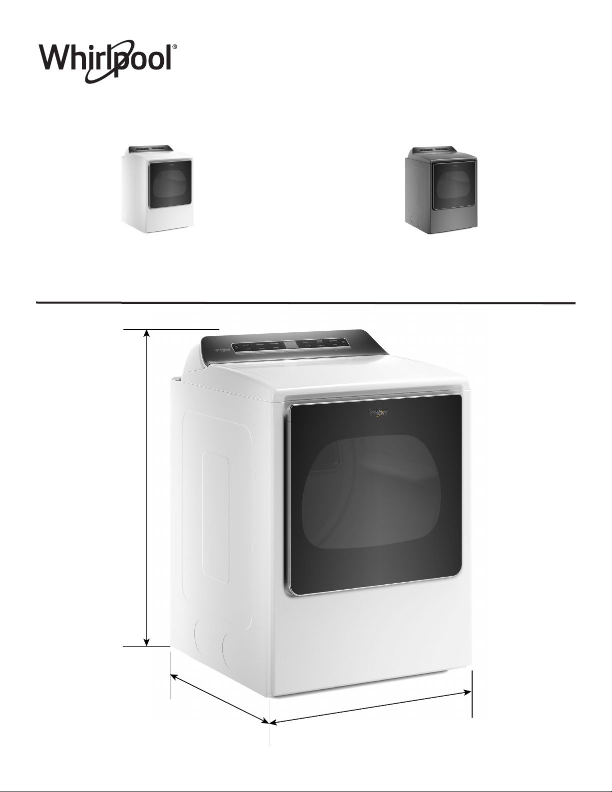
Whirlpool® Front Load Electric/Gas Dryer
with Steam Refresh Cycle, Advanced
Moisture Sensing Technology - 8.8 cu. ft.
White Available
WED8120HW - Electric
WGD8120HW - Gas
42 5∕16"
Height
Chrome Shadow Available
WED8120HC - Electric
WGD8120HC - Gas
W11412665A
32 11∕16"
Depth
29"
Width
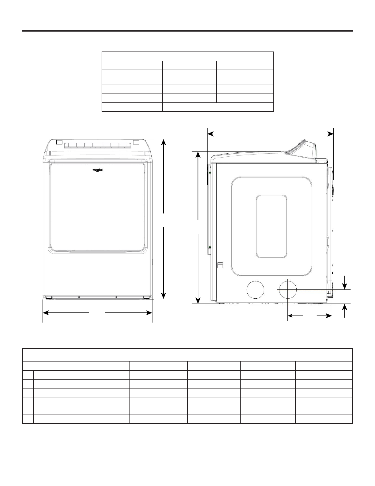
DETAILED PLANNING DIMENSIONS
WARNING: To reduce the risk of re, electric shock, or injury to persons, read the IMPORTANT SAFETY INSTRUCTIONS and
INSTALLATION INSTRUCTIONS, located in your appliance's Owner's Manual, before installing and operating this appliance.
Electrical Requirements
Fuel Type Electric Gas
Minimum Circuit
Amperage Rating
Maximum AMP Draw 26 A 6 A
Operating Voltage 240 V - AC only 120 V - AC only
Operating Frequency 60 Hz
30 A 15 A
D
A
C
B
F
Product Dimensions
in (min) mm (min) in (max) mm (max)
A Height (with feet) 42 5∕
16
1075.24 43 5∕
B Width 29 737 - C Top Height (with feet) 39 1∕
D Depth 32 11∕
E Side Vent Height (feet min) 3 5∕
F Side Vent (from back) 11 3∕
4
16
8
8
996.4 40 1∕
830 - -
92.80 4 5∕
289.36 - -
16
4
8
1100.64
1021.8
118.2
E
2
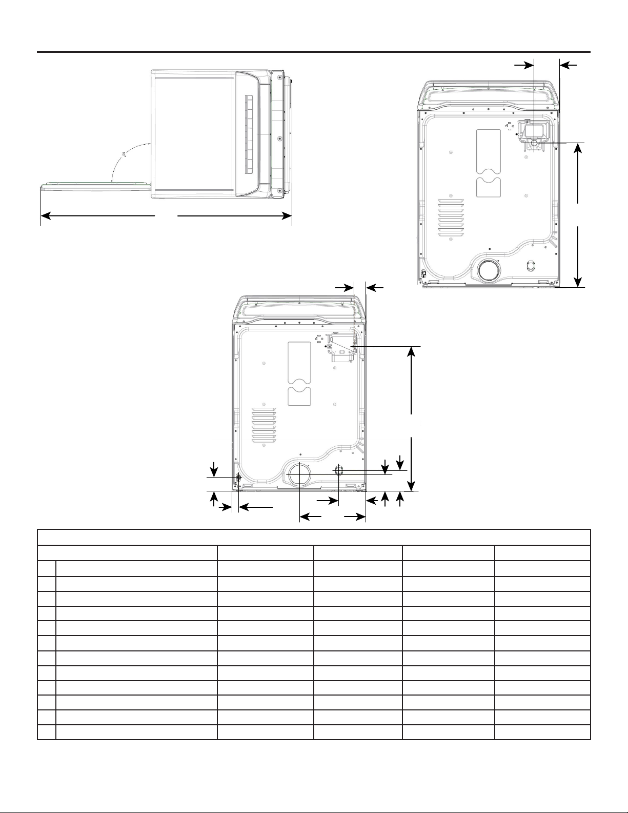
DETAILED PLANNING DIMENSIONS
H
G
I
J
K
P
L
M
Q
N
O
Product Dimensions
in (min) mm (min) in (max) mm (max)
G
Depth with Door Open 56 5∕
H Strain Relief from Side (elec) 5 1∕
I Strain Relief Height (elec) 29 9∕
J Power Cord from Side (gas) 2 5∕
K Power Cord Height (gas) 30 5∕
Power Cord Length (gas) 72 7∕
L Gas Valve Height 1 7∕
M Gas Valve from Side 3 76.87 - -
N Exhaust Duct Height 3 9∕
O Exhaust Duct from Side 14 7∕
P Water Inlet Height (steam models) 4 ½ 114.25 5 ½ 139.65
Q Water Inlet from Side (steam models) 5 7∕
3
8
4
16
8
16
16
16
16
16
8
1438 - -
132.94 - -
751.16 30 9∕
16
776.56
66.29 - -
796.57 31 5∕
16
794.97
1840.25 - -
36.14 2 7∕
91.12 4 9∕
16
16
61.54
116.52
366.70 - -
150 - -
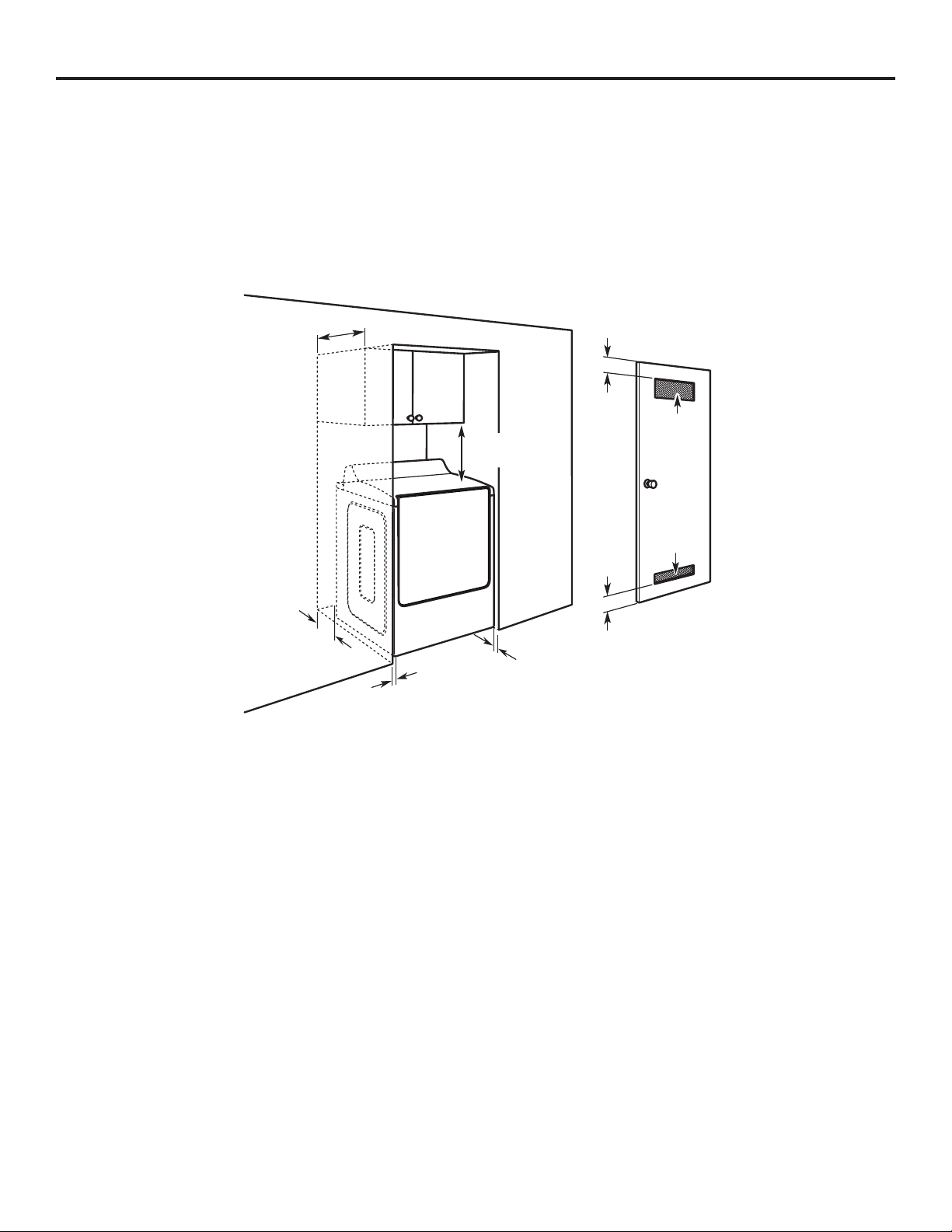
DETAILED PLANNING DIMENSIONS
Spacing for recessed area or closet installation
The dimensions shown are for the recommended spacing allowed.
Ƀ Additional spacing should be considered for ease of installation and servicing.
Ƀ Additional clearances might be required for wall, door, and oor moldings.
Ƀ Additional spacing of 1" (25 mm) on all sides of the dryer is recommended to reduce noise transfer.
Ƀ For closet installation, with a door, minimum ventilation openings in the top and bottom of the door are required. Louvered doors
with equivalent ventilations openings are acceptable.
Ƀ Companion appliance spacing should also be considered.
14" max
(356 mm)
3"
(76 mm)
18"
(460 mm)
48 in.
(310 cm
2
)
6"/0"*
(152 mm/0 mm)
1"/0"*
(25 mm/0 mm)
*Recommended/Minimum spacing
1"
(25 mm)
3"
(76 mm)
24 in.
(155 cm
2
)
4
 Loading...