

Whirlpool WA 4740, WA 1402, WA 4520, WA 4330, WA 4730 INSTRUCTION FOR USE
...
QUICK REFERENCE GUIDE GB
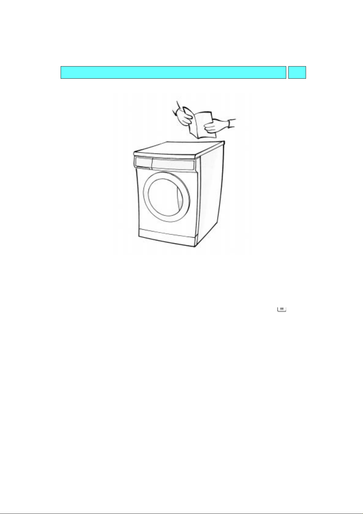
BEFORE USING THE APPLIANCE FOR THE FIRST TIME:
• FOLLOW THE “INSTALLATION INSTRUCTIONS
• REMOVE THE TRANSIT BOLTS BEFORE USING THE APPLIANCE.
• First wash cycle without laundry:
Turn on the tap.
1.
Close the appliance door.
2.
Pour a small amount of detergent (about 30 ml) into the detergent dispenser .
3.
Select a short program (see programme chart).
4.
Press the
5.
This initial cycle serves to eliminate any water remaining after your appliance was tested at
the factory.
NORMAL DAILY USE:
Turn on the tap.
1.
Sort the wash according to fabric type and colour and load the appliance.
2.
Close the door.
3.
Put in detergent and any additives required into the dispenser.
4.
Select the programme, the temperature and any special options required.
5.
Press the
6.
“On/Off”
“On/Off”
button.
button.
”.
19

GB CONTENTS
INSTALLATION INSTRUCTIONS
APPLIANCE AND ACCESSORIES
CHILD SAFETY
PROTECTING THE ENVIRONMENT
SAFETY INSTRUCTIONS
TRANSPORT / HANDLING
PREPARING THE WASH
DETERGENT AND ADDITIVES
DYEING AND BLEACHING
PROGRAMME SELECTION / PROGRAMME START
PAGE
PAGE
PAGE
PAGE
PAGE
PAGE
PAGE
PAGE
PAGE
PAGE
21
25
25
26
26
26
27
28
29
29
DOOR LOCK / PROGRAMME END
CHANGING / INTERRUPTING /
CLEARING PROGRAMME
REMOVING THE FILTER
DRAINING RESIDUAL WATER
CARE AND MAINTENANCE
TROUBLESHOOTING GUIDE
AFTER-SALES SERVICE
20
PAGE
PAGE
PAGE
PAGE
PAGE
PAGE
PAGE
30
30
31
32
32
33
34
INSTALLATION INSTRUCTIONS
Never move the appliance by carrying it at the
worktop.
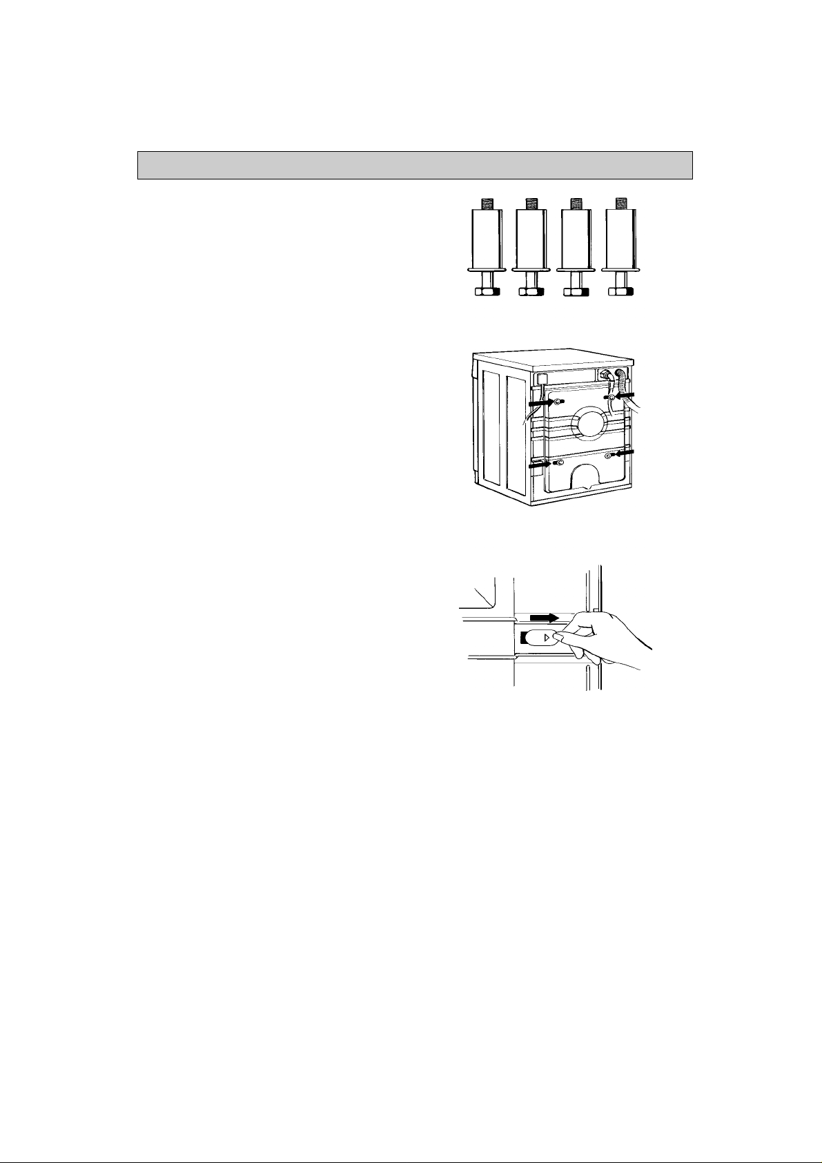
TRANSIT BOLTS
The appliance is fitted with transit bolts to prevent
internal damage during transport.
Before using the machine you must remove
the transit bolts (Fig. 1).
1. Slacken the four bolts with the wren ch
supplied (Fig. 2).
2. Unscrew the bolts by hand.
3. Holding the bolt head, pull each bolt through
the wide part of the holes.
4. Close the holes with the plastic covers supplied;
insert the covers in the wide part of the hole and
slide them toward the narrow part until they click
into place (Fig. 3).
5. Keep the transit bolts for future us e.
Important
Whenever the appliance is transported, the transit
bolts must be refitted.
Pry up the plastic covers with a screwdrive r, slide
them in the opposite direction to the arrow and
remove. Insert the transit bolts, performing the
steps for removal in reverse order.
Fig. 1
Fig. 2
Fig. 3
21
INSTALLATION INSTRUCTIONS
INSTALLATION
•
Install the appliance on a so lid and level floor
surface, preferably in a corner of the room.
•
Make sure that all four feet are stable and resting on
the floor and then check that the appliance is
perfectly level (use a spirit level).
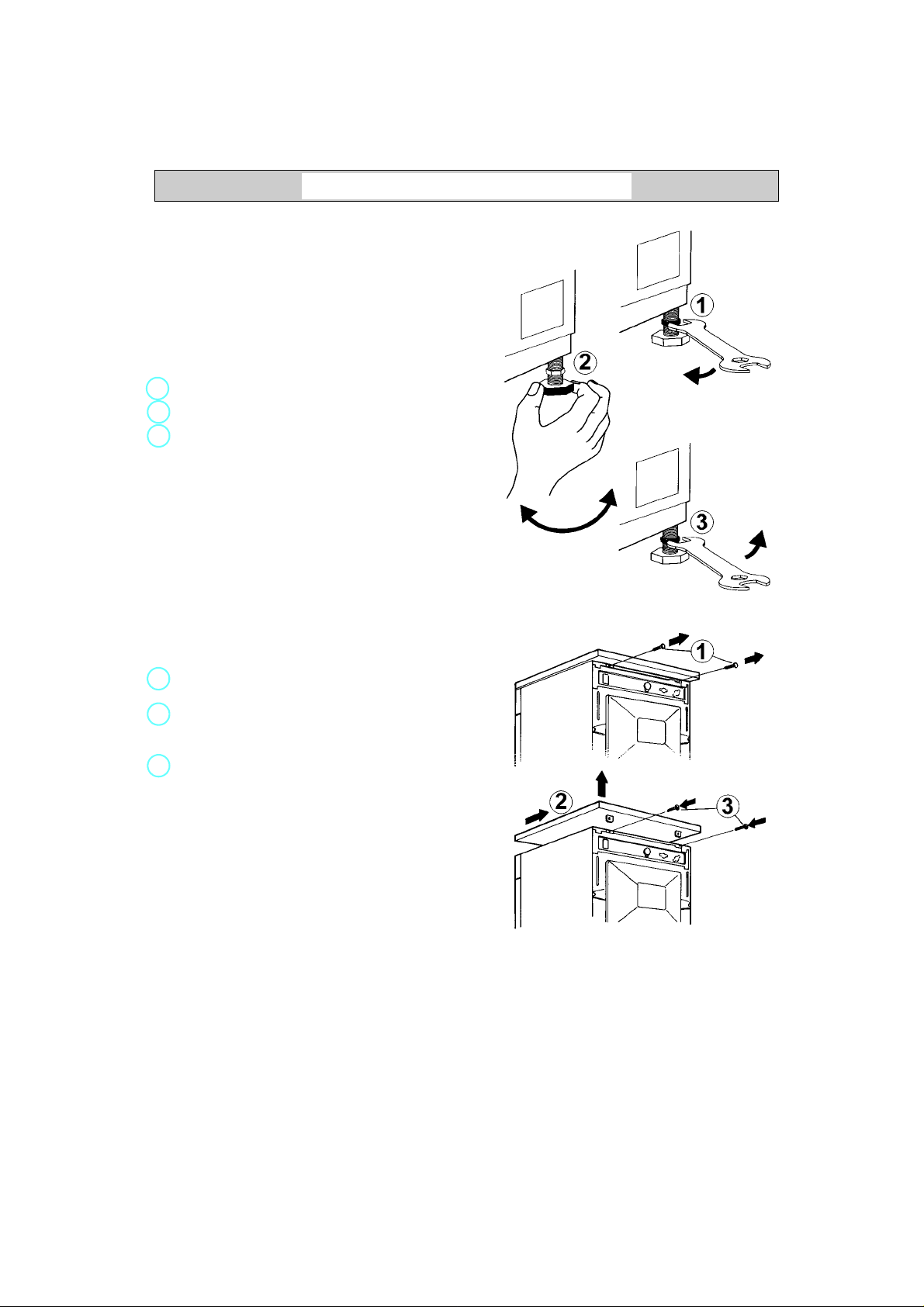
•
If the floor is uneven, adjust the levelling feet as
required (do not insert pieces of wood etc. under the
feet):
1.
Slacken the locknut using the w re nc h s up pli ed .
2.
Adjust the height of the foot, turning it by hand.
3.
Tighten the locknut by turning it anti-clockwi se
towards the appliance casing.
•
If the appliance is to be installed on a wooden floor,
distribute the weight by placing it on a 60 x 60 cm
sheet of plywood at least 3 cm in thickness.
Secure the plywood sheet to the fl oo r.
WORKTOP / COVER PANEL
The appliance must only be installed beneath a
continuous fitted kitchen worktop.
If the appliance will be built under it is mandatory
to use the cover panel UBS. This can be obtained
from specialist shops or from After-Sales Service.
•
Unplug the appliance.
1.
Unscrew the worktop fixing screws from the rear of
the appliance.
2.
Slide the worktop fully backward and lift it upwards
to remove. Install the cover panel following th e
relative instructions.
3.
Refit the fixing screws and t igh te n th em .
BUILD-UNDER OPENING DIMENSIONS
Width 600 mm
Height 825 mm
Depth 600 mm
WARNING:
Only plug the appliance into th e mai ns p owe r so cke t
after you have fitted the cover panel or the appliance
worktop.
22
INSTALLATION INSTRUCTIONS
WATER SUPPLY
•
Water supply: cold water only
•
Tap: 3/4” threaded hose connection
•
Pressure: 100-1000 kPa (1-10 bar).
WATER INLET HOSE
1.
The dirt strainer (already premounted on the hose
end or included in the accessories) must be
inserted into the threaded tap coupling.
2.
Carefully screw the hose connect i o n ont o th e ta p
preferably by hand. Make sure there are no kinks in
the hose.
3.
Check water-tightness of tap and appliance
connections by turning the tap completely on.
•
If the hose is too short, repla ce it w i th a s uit ab le
length of pressure resistant ho se (10 00 kPa min,
EN 50084 approved type).
•
Periodically check the hose for brit tl en ess a nd
cracks and replace if necessary.
•
The appliance can be connected without an antibackpressure valve.
•
Install the appliance in accordance wit h regulations
of your local water company.
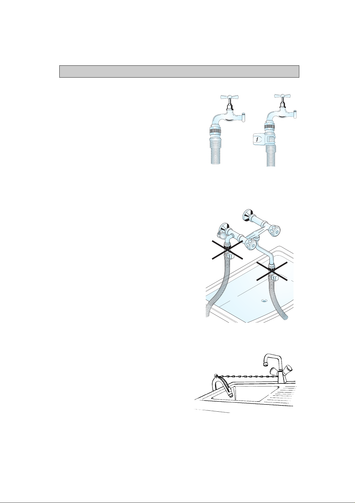
WATER STOP (depends on model)
•
Screw the threaded connector with the filter in serted
onto the tap. Open the water tap fully and chec k the
water-tightness of the connect io n p oi nt .
•
The appliance must not be connected to the mixing
tap of a non-pressurized water heater.
•
The inlet hose and the plastic enclosure at the tap
connection contain electrical co mp on en ts.
N.B. Do not cut the hose and do not immerse
the plastic enclosure in water.
•
If the flexible hose is damaged, un plug th e
appliance from the mains immediately.
•
If the hose is too short, repla ce it w i th a 3 m Wa te r
Stop hose (available from After-Sales Service or
from your dealer). This operation must be carried
out exclusively by a licensed electrician.
DRAINING
•
Connecting the water drain hose.
Connect the drain hose to the siphon or hook it
over the edge of a sink by means of the “U” bend
(see figure).
The drain hose should not be hooked onto small
washbasins.
Max. drain height: 1.25 m
If you need to add an extension, use a flexible
hose of the same type and secure t he un io n wit h
screw-on hose clips.
Max. drain hose length: 2.50 m
Important:
Make sure there are no kinks in the hose. Secure
the hose so that it cannot f al l dow n w hil e th e
appliance is running.
Straight hose Water Stop hose
23
 Loading...