

Whirlpool W10573709B, W10573710B User Manual

ELECTRIC DRYER INSTALLATION INSTRUCTIONS
Table of Contents
DRYER SAFETY .........................................................................2
INSTALLATION REQUIREMENTS ............................................. 3
Tools and Parts ...................................................................... 3
LOCATION REQUIREMENTS .................................................... 4
ELECTRICAL REQUIREMENTS ................................................ 5
INSTALL LEVELING LEGS ......................................................... 6
ELECTRICAL INSTALLATION ...................................................7
Power Supply Cord Connection ........................................... 8
Direct Wire Connection ....................................................... 10
VENTING ................................................................................... 12
Venting Requirements .........................................................12
Plan Vent System .................................................................13
Install Vent System ..............................................................15
CONNECT INLET HOSE (STEAM MODEL ONLY).................. 15
CONNECT VENT ...................................................................... 16
LEVEL DRYER .......................................................................... 17
COMPLETE INSTALLATION CHECKLIST .............................. 17
DOOR REVERSAL (OPTIONAL) .............................................. 18
Para una version de estas instrucciones en español, visite www.Whirlpool.com
INSTALLATION NOTES
Date of purchase: _________________________________
Date of installation: _______________________________
Installer: ________________________________________
Model number: ___________________________________
Serial number: ___________________________________
W10573709B
W10573710B - SP
1
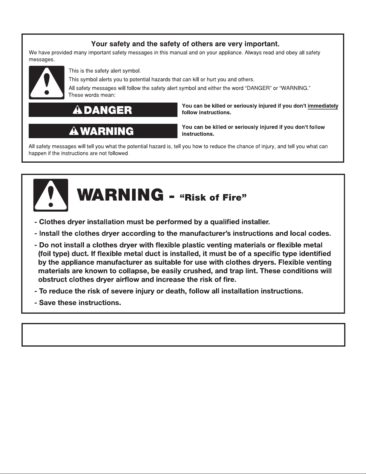
DRYER SAFETY
IMPORTANT: When discarding or storing your old clothes dryer, remove the door.
2
INSTALLATION REQUIREMENTS
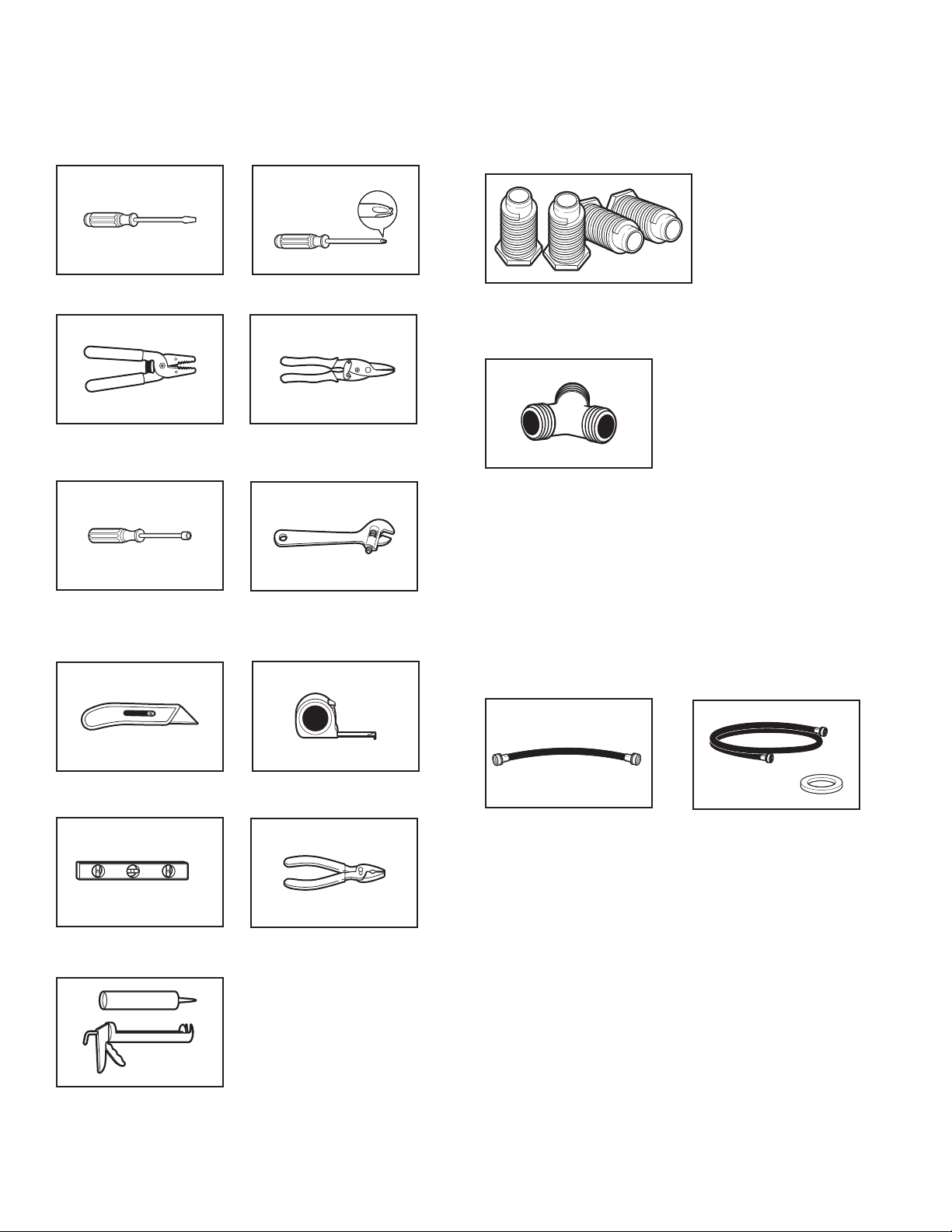
TOOLS AND PARTS
Gather the required tools and parts before starting installation.
Tools needed:
Flat-blade screwdriver #2 Phillips screwdriver
Wire stripper (direct wire
installations)
1/4" and 5/16" nut driver
(recommended)
Tin snips (new vent
installations)
Adjustable wrench that
opens to 1" (25 mm) or
hex-head socket wrench
Parts supplied (all models):
Leveling legs (4)
Parts supplied (steam models):
“Y” connector
Parts package is located in dryer drum. Check that all parts
are included.
NOTE: Do not use leveling legs supplied with dryer if installing
with a pedestal or a stack kit.
Parts needed: (Not supplied with dryer)
■ Vent clamps
■ Vent elbows and vent work
Utility knife
Level
Caulking gun and
compound (for installing
new exhaust vent)
Tape measure
Pliers
Parts needed (steam models):
2' (0.6 m) inlet hose
Additional parts may be required, depending in your installation.
Check local codes. Check existing electrical supply and venting.
Read “Electrical Requirements” and “Venting Requirements”
before purchasing parts.
5' (1.52 m) inlet hose
and rubber washer
If using a power supply cord:
Use a UL listed power supply cord kit marked for use with
clothes dryers. The kit should contain:
■ A UL listed 30-amp power supply cord, rated 120/240 volt
minimum. The cord should be type SRD or SRDT and be
at least 4 ft. (1.22 m) long. The wires that connect to
the dryer must end in ring terminals or spade terminals
with upturned ends.
■ A UL listed strain relief.
Optional Equipment: (Not supplied with dryer)
Refer to your Use and Care Guide for information about
accessories available for your dryer.
3
LOCATION REQUIREMENTS
Check code requirements. Some codes limit, or do not permit,
installing dryer in garages, closets, mobile homes, or sleeping
quarters. Contact your local building inspector.
You will need:
■ A location allowing for proper exhaust installation. See
“Venting Requirements.”
■ A separate 30 amp circuit.
■ If using power supply cord, a grounded electrical outlet
located within 2 ft. (610 mm) of either side of dryer. See
“Electrical Requirements.”
■ Floor must support dryer weight of 200 lbs. (90.7 kg). Also
consider weight of companion appliance.
■ Cold water faucets located within 4 ft. (1.2 m) of the water ll
valves, and water pressure of 20 – 120 psi (138 – 827 kPa).
You may use the water supply for your washer using the
supplied “Y” connector and a short hose (which you will
need to purchase).
■ Level oor with maximum slope of 1" (25 mm) under entire
dryer. If slope is greater than 1" (25 mm), install Extended
Dryer Feet Kit, Part Number 279810. If not level, clothes
may not tumble properly and automatic sensor cycles may
not operate correctly.
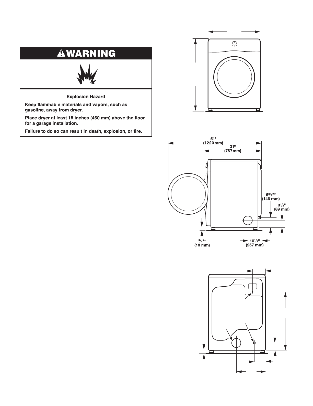
■ For garage installation, place dryer at least 18" (460 mm) above
oor. If using a pedestal, you will need 18" (460 mm) to bottom
of dryer.
■ The dryer must not be installed or stored in an area where it will
be exposed to water and/or weather.
IMPORTANT: Do not operate, install, or store dryer where
it will be exposed to water, weather, or at temperatures below
40° F (4° C). Lower temperatures may cause dryer not to
shut off at end of automatic sensor cycles, resulting in longer
drying times.
Installation Clearances
For each arrangement, consider allowing more space for ease
of installation and servicing; spacing for companion appliances
and clearances for walls, doors, and oor moldings. Space
must be large enough to allow door to fully open. Add spacing
on all sides of dryer to reduce noise transfer. If a closet door
or louvered door is installed, top and bottom air openings
in door are required.
Check code requirements. Some codes limit, or do not permit,
installation of the dryer in garages, closets, mobile homes, or
sleeping quarters. Contact your local building inspector.
DRYER DIMENSIONS
Front view:
383/4" Min.
(984 mm)
39" Max.
(990 mm)
Side view:
Back view:
NOTE: Most
installations
require a minimum
of 5" (127 mm)
clearance behind
dryer for exhaust
vent with elbow.
See “Venting
Requirements.”
3
/4"*
(18 mm)
* Approx. measurement.
27"
(686 mm)
Power supply
cord/cable
Water inlet
(Steam
models only)
Vent
3
14
/8"
(365 mm)
61/2"
(165 mm)
(759 mm)
1
3
/2"*
(89 mm)
1
6
/8"*
(156 mm)
29
7
/8"*
4
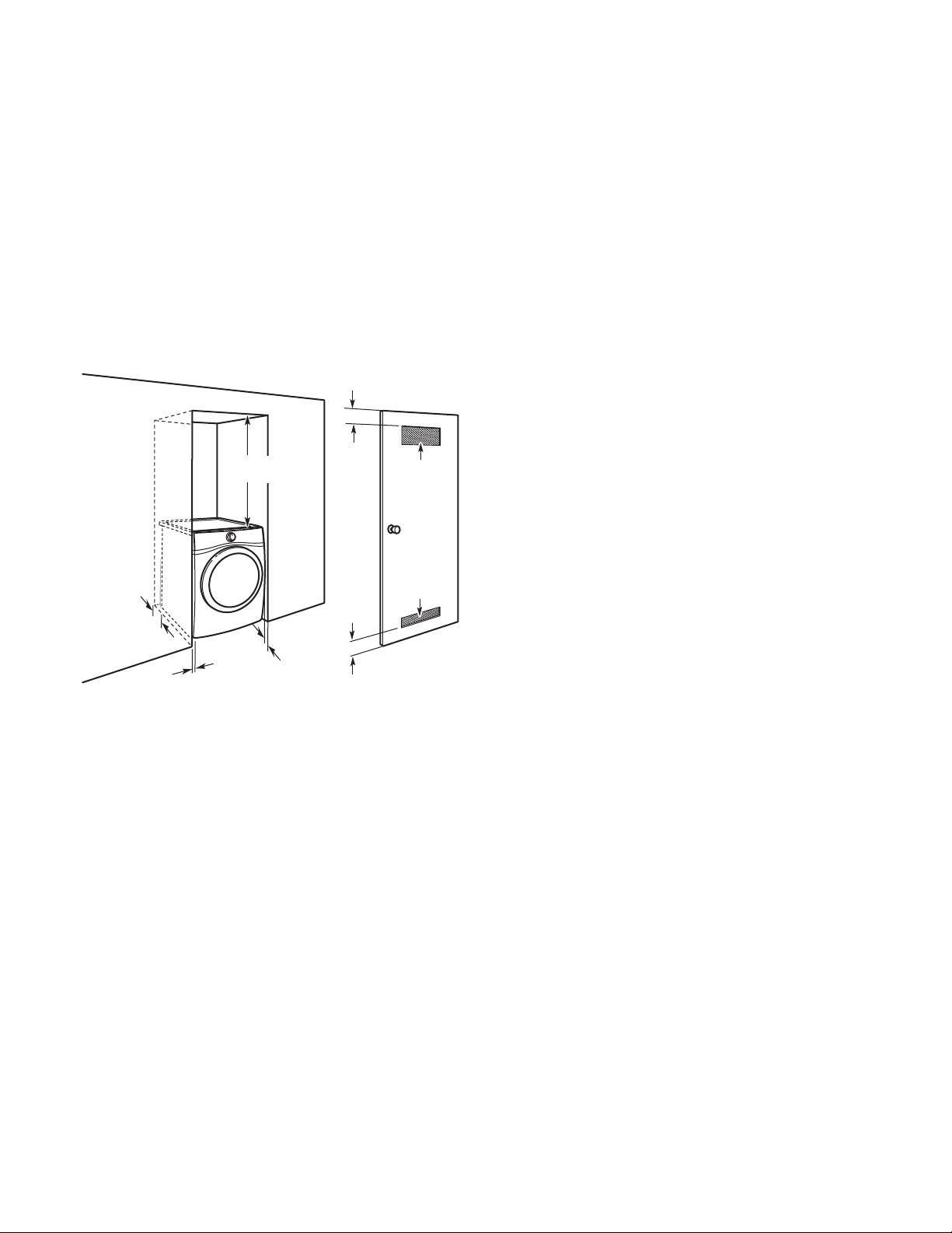
Installation spacing for recessed area
or closet installation
All dimensions show recommended and minimum spacing
allowed.
■ Additional spacing should be considered for ease of
installation and servicing.
■ Additional clearances might be required for wall, door, oor
moldings, and dryer venting.
■ Additional spacing should be considered on all sides of the
dryer to reduce noise transfer.
■ For closet installation, with a door, minimum ventilation
openings in the top and bottom of the door are required.
Louvered doors with equivalent ventilation openings are
acceptable.
■ Companion appliance spacing should also be considered.
Recommended installation clearances (dryer only):
3"
(76 mm)
3"
(76 mm)
48 in.2 min.
(310 cm
24 in.2 min.
(155 cm2)
*
5"
(127 mm)
18" min.
(457 mm)
1"
*
(25 mm)
1"
(25 mm)
* 0" (0 mm) spacing is allowed.
Mobile home – Additional installation requirements:
This dryer is suitable for mobile home installations.
The installation must conform to the Manufactured
Home Construction and Safety Standard, Title 24 CFR,
Part 3280 (formerly the Federal Standard for Mobile home
construction and Safety, Title 24, HUD Part 280) or Standard
CAN/CSA-Z240 MH.
Mobile home installations require:
■ Metal exhaust system hardware, available for purchase from
your dealer. For further information, see “Assistance or
Service” section in your Use and Care Guide.
■ Special provisions must be made in mobile homes to
introduce outside air into dryer. Openings (such as a nearby
window) should be at least twice as large as dryer exhaust
opening.
ELECTRICAL REQUIREMENTS
It is your responsibility:
■ To contact a qualied electrical installer.
■ To be sure that the electrical connection is adequate and
in conformance with the National Electrical Code, ANSI/
NFPA 70 – latest edition and all local codes and ordinances.
The National Electrical Code requires a 4-wire power supply
connection for homes built after 1996, dryer circuits involved
in remodeling after 1996, and all mobile home installations.
A copy of the above code standards can be obtained from:
National Fire Protection Association, One Batterymarch Park,
Quincy, MA 02269.
■ To supply the required 3 or 4 wire, single phase, 120/240
volt, 60 Hz, AC only electrical supply (or 3 or 4 wire, 120/208
volt electrical supply, if specied on the serial/rating plate)
on a separate 30-amp circuit, fused on both sides of the line.
Connect to an individual branch circuit. Do not have a fuse in
the neutral or grounding circuit.
■ Do not use an extension cord.
■ If codes permit and a separate ground wire is used, it is
recommended that a qualied electrician determine that
the ground path is adequate.
2
)
Electrical Connection
To properly install your dryer, you must determine the type of
electrical connection you will be using and follow the instructions
provided for it here.
■ This dryer is manufactured ready to install with a 3-wire
electrical supply connection. The neutral ground conductor
is permanently connected to the neutral conductor (white wire)
within the dryer. If the dryer is installed with a 4-wire electrical
supply connection, the neutral ground conductor must be
removed from the external ground connector (green screw),
and secured under the neutral terminal (center or white wire)
of the terminal block. When the neutral ground conductor is
secured under the neutral terminal (center or white wire) of the
terminal block, the dryer cabinet is isolated from the neutral
conductor. The green ground wire of the 4-wire power cord
must be secured to the dryer cabinet with the green
ground screw.
■ If local codes do not permit the connection of a neutral
ground wire to the neutral wire, see “Optional 3-wire
connection” section.
■ A 4-wire power supply connection must be used when the
appliance is installed in a location where grounding through
the neutral conductor is prohibited. Grounding through the
neutral is prohibited for (1) new branch-circuit installations after
1996, (2) mobile homes, (3) recreational vehicles, and (4) areas
where local codes prohibit grounding through the neutral
conductors.
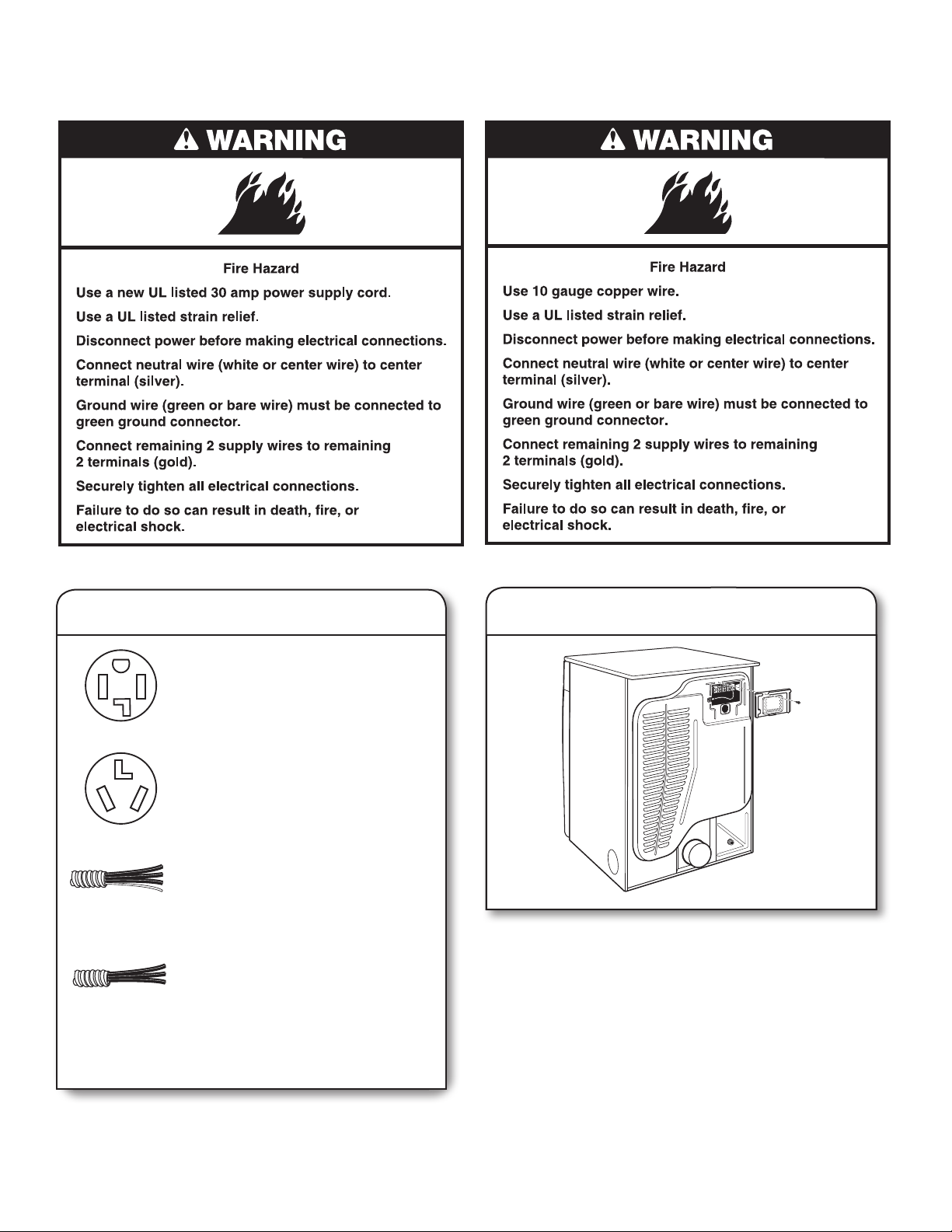
If using a power supply cord:
Use a UL listed power supply cord kit marked for use with
clothes dryers. The kit should contain:
■ A UL listed 30-amp power supply cord, rated 120/240 volt
minimum. The cord should be type SRD or SRDT and be
at least 4 ft. (1.22 m) long. The wires that connect to
the dryer must end in ring terminals or spade terminals
with upturned ends.
■ A UL listed strain relief.
5
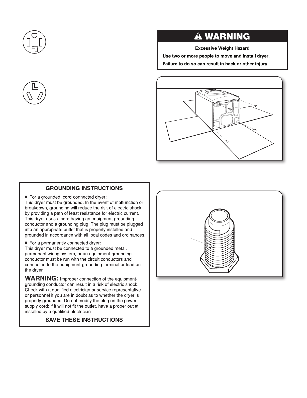
If your outlet looks like this:
Then choose a 4-wire power supply cord with
ring or spade terminals and UL listed strain
relief. The 4-wire power supply cord, at least
4 ft. (1.22 m) long, must have four 10-gauge
copper wires and match a 4-wire receptacle of
NEMA Type 14-30R. The ground wire (ground
4-wire receptacle
(14-30R)
conductor) may be either green or bare. The
neutral conductor must be identied by a white
cover.
INSTALL LEVELING LEGS
Then choose a 3-wire power supply cord with
ring or spade terminals and UL listed strain
relief. The 3-wire power supply cord, at least
4 ft. (1.22 m) long, must have three 10-gauge
3-wire receptacle
(10-30R)
copper wires and match a 3-wire receptacle
of NEMA Type 10-30R.
If connecting by direct wire:
Power supply cable must match power supply (4-wire or 3-wire)
and be:
■ Flexible armored cable or nonmetallic sheathed copper cable
(with ground wire), covered with exible metallic conduit. All
current-carrying wires must be insulated.
■ 10-gauge solid copper wire (do not use aluminum) at least
5 ft. (1.52 m) long.
1. Prepare dryer for leveling legs
To avoid damaging oor, use a large at piece of cardboard
from dryer carton; place under entire back edge of dryer.
Firmly grasp dryer body (not console panel) and gently lay
dryer down on cardboard.
2. Screw in leveling legs
diamond
marking
Examine leveling legs, nd diamond marking. Screw legs into
leg holes by hand – use a wrench to nish turning legs until
diamond marking is no longer visible.
Place a carton corner post from dryer packaging under each
of the 2 dryer back corners. Stand the dryer up. Slide the
dryer on the corner posts until it is close to its nal location.
Leave enough room to connect the exhaust vent.
6
ELECTRIC INSTALLATION
For power supply cord installations:
For direct wire installations:
Before you start: disconnect power.
1. Choose electrical connection type
Power supply cord 4-wire receptacle
(NEMA Type 14-30R).
Go to “Power Supply Cord Connection.”
Power supply cord 3-wire receptacle
(NEMA Type 10-30R).
Go to “Power Supply Cord Connection.”
4-wire direct connection:
Go to “Direct Wire Connection.”
3-wire direct connection:
Go to “Direct Wire Connection.”
2. Remove terminal block cover
Remove hold-down screw and terminal block cover.
NOTE: If local codes do not permit connection of a
cabinet-ground conductor to neutral wire, go to “Optional
3-wire connection.” This connection may be used with
either a power supply cord or a direct wire connection.
7
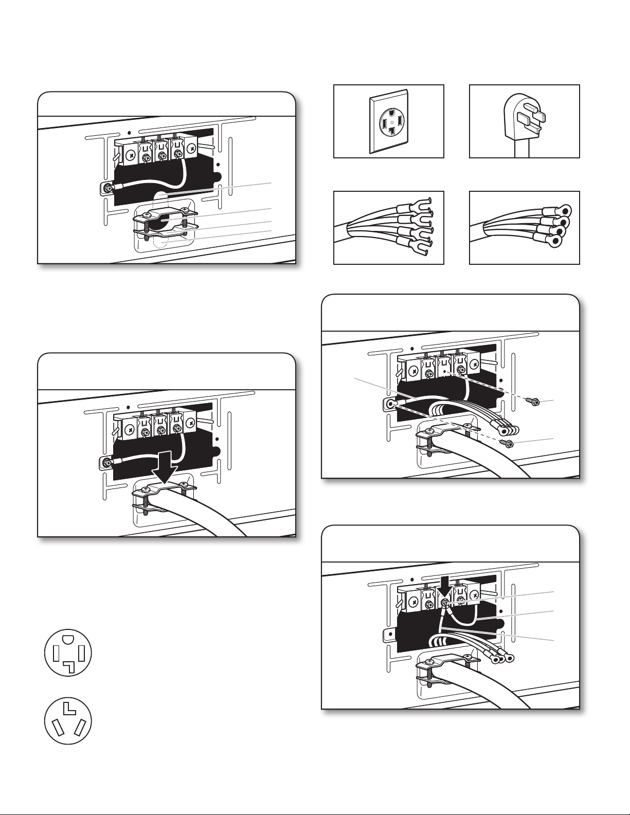
Power Supply Cord Connection
Power supply cord strain relief:
1. Attach power supply cord strain relief
4-Wire Power Supply Cord Connection
IMPORTANT: A 4-wire connection is required for mobile homes
and where local codes do not permit the use of 3-wire connections.
A
B
C
D
Remove the screws from a 3/4" (19 mm) UL listed strain relief
(UL marking on strain relief). Put the tabs of the two clamp
sections (C) into the hole below the terminal block opening
(B) so that one tab is pointing up (A) and the other is pointing
down (D), and hold in place. Tighten strain relief screws just
enough to hold the two clamp sections (C) together.
2. Attach power supply cord
to strain relief
4-wire receptacle (NEMA
type 14-30R)
Spade terminals with
upturned ends
4-prong plug
Ring terminals
1. Prepare to connect neutral ground
wire and neutral wire
E
B
A
Put power supply cord through the strain relief. Be sure that
the wire insulation on the power supply cord is inside the
strain relief. The strain relief should have a tight t with the
dryer cabinet and be in a horizontal position. Do not further
tighten strain relief screws at this point.
If your outlet looks like this:
Power supply cord 4-wire receptacle
(NEMA Type 14-30R):
Go to “4-Wire Power Supply Cord
Connection” on this page.
Power supply cord 3-wire receptacle
(NEMA Type 10-30R):
Go to “3-Wire Power Supply Cord
Connection” on page 9.
8
Remove center terminal block screw (B). Remove neutral
ground wire (E) from green external ground conductor screw (A).
2. Connect neutral ground wire and
neutral wire
B
E
C
Connect neutral ground wire (E) and neutral wire (white or
center) (C) of power supply cord under center terminal block
screw (B). Tighten screw.
 Loading...