

Page 1
TKirlpool
CORPORATION
ECKMF-28
HOW TO INSTALL
YOUR AUTOMATIC
ICE MAKER
USE THESE INSTRUCTIONS ONLY FOR
28 INCH TOP FREEZER REFRIGERATORS
Part No 939024 A
Page 2
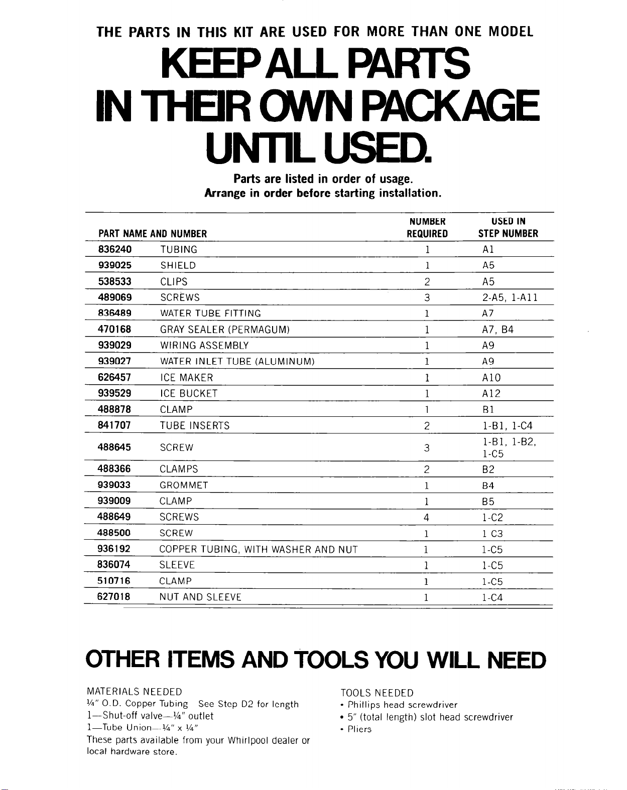
THE PARTS IN THIS KIT ARE USED FOR MORE THAN ONE MODEL
KEEPALL PARTS
IN THEIR WVN PACKAGE
UNTIL USED.
Parts are listed in order of usage.
Arrange in order before starting installation.
NUMBER
PART NAME AND NUMBER
TUBING
939025 SHIELD
538533
489069 SCREWS
836489 WATER TUBE FITTING
470168 GRAY SEALER (PERMAGUM)
939029 WIRING ASSEMBLY
939027 WATER INLET TUBE (ALUMINUM)
626457 ICE MAKER
939529 ICE BUCKET
488878 CLAMP
841707 TUBE INSERTS
488645
488366 CLAMPS
939033 GROMMET 1
939009
488649
488500
936192
836074 SLEEVE 1
510716
6270 1 B
CLIPS
CLAMP
SCREWS
SCREW
COPPER TUBING, WITH WASHER AND NUT
CLAMP
NUT AND SLEEVE
REQUIRED
4
1 l-C5
2
3
2
2
1
1
1
1
1
1
1
1
1
USED IN
STEP NUMBER
Al
A5
A5
2-A5, l-Al 1
A7. B4
A9
A10
Al2
Bl
l-Bl. l-C4
1-Bl, l-B2,
1-c!i
82
B4
B5
l-C2
l-C5
l-C4
OTHER ITEMS AND TOOLS YOU WILL NEED
MATERIALS NEEDED
‘/4” O.D. Copper Tubing-See Step D2 for length
l-Shut-off valve--‘/a” outlet
l-Tube Union--‘/a” x %”
These parts available from your Whirlpool dealer or
local hardware store.
TOOLS NEEDED
l
Phillips head screwdriver
l
5” (total length) slot head screwdriver
l
Pliers
Page 3
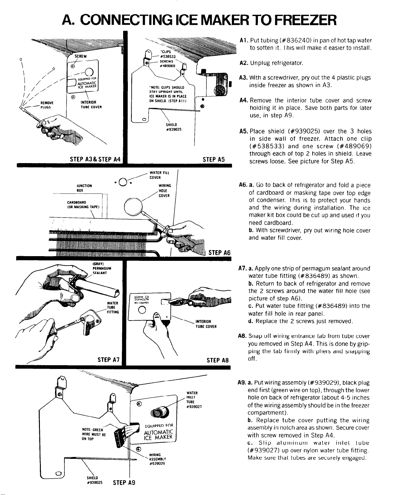
A. CONNECTING ICE MAKER TO FREEZER
Al. Put tubing (#836240) in pan of hot tap water
to soften it. This will make it easier to install.
A2. Unplug refrigerator.
A3. With a screwdriver, pry out the 4 plastic plugs
inside freezer as shown in A3.
A4. Remove the interior tube cover and screw
holding it in place. Save both parts for later
use, in step A9.
A5. Place shield (#939025) over the 3 holes
in side wall of freezer. Attach one clip
(#538533) and one screw (#489069)
through each of top 2 holes in shield. Leave
screws loose. See picture for Step A5.
A6. a. Go to back of refrigerator and fold a piece
of cardboard or masking tape over top edge
of condenser. This is to protect your hands
and the wiring during installation. The Ice
maker kit box could be cut up and used if you
need cardboard.
b. With screwdriver, pry out wiring hole cover
and water fill cover.
STEP A3&STEP A4 1
‘NOTE: CLIPS SHOULD
STAY UPRIGHT UNTIL
ICE MAKER IS IN PLACE
ON SHIELD. (STEP Al 1)
STEP A5
I
NOTE: CREEL’
WIRE MUST BE
ON TOP
EQy’TPED FoR I
AUlOMATIC
ICE MAKER
A7. a. Apply one strip of permagum sealant around
water tube fitting (#836489) as shown.
b. Return to back of refrigerator and remove
the 2 screws around the water fill hole (see
picture of step A6).
c. Put water tube fitting (#836489) into the
water fill hole in rear panel.
d. Replace the 2 screws just removed.
TUBE COVER
A8. Snap off wiring entrance tab from tube cover
you removed in Step A4. This is done by gripping the tab firmly with pliers and snapping
off.
A9. a. Put wiring assembly (#939029), black plug
end first (green wire on top), through the lower
hole on back of refrigerator (about 4-5 inches
of the wiring assembly should be in the freezer
compartment).
b. Replace tube cover putting the wiring
assembly in notch area as shown. Secure cover
I
with screw removed in Step A4.
c. Slip aluminum water inlet tube
(#939027) up over nylon water tube fitting.
Make sure that tubes are securely engaged.
ly939025
STEP A9
Page 4

STEP A10
NOTE. GREEN
WIRE MUST BE
ROTATE CLIPS
TIGHTEN SCREWS
AlO. Connect Ice Maker to wiring assembly. Place
the ice maker on the side of the freezer so:
1. Wiring lays between shield and Ice Maker.
2. Plug is flat against the shield.
3. Wiring is above the bracket on the back of
Ice Maker.
WARNING-DO NOT PINCH WIRES BETWEEN
BRACKET AND SIDE OF FREEZER.
Al 1. Put screw (#489069) through bottom bracket
and into freezer wall, then turn the 2 top clips
down (Step A5). Tighten all 3 screws.
A12. Place ice bucket under Ice Maker.
\
SCREW
Y‘w9069
\
BRACKET
B. INSTALLING WATER LINE AND WIRING
ON BACKOF CABINET
Bl. Place clamp (#488878) over spout of water
tube fitting. Put tube insert (#841707) in one
end of tubing that has been soaking in hot
water. Put tube insert and end of tubing into
spout. Tighten clamp with screw (#488645).
CLAMP Y4a8816
(WITH SCREW Y4.38645)
STEPAll -STEPA
B2. Slide 2 clamps (#488366) over tubing.
Remove the screw from cabinet and attach
upper clamp to cabinet with this screw. Use
screw (#488645) from kit to attach lower
clamp to cabinet. Hold wires away from screw
when tightening.
CLAMPS
-48
(FEEDS UNDER
WIRING ASSEMBLY
Page 5

83. Remove the metal junction box and save the
2 mounting screws.
a. Bend back ears of 3 wire plug on ice maker
wiring assembly.
b. With the green wire up, snap the plug into
hole in side of junction box.
c. Connect the 3 wire plug into mating part
in junction box. Remount metal junction box.
WARNING-DO NOT PINCH WIRES BETWEEN
JUNCTION BOX AND CABINET.
84. Place split grommet (#939033) around wiring
assembly and push into cabinet hole. Seal
space between wiring and grommet with permagum sealant.
WHITE AND TAN
WIRES
B5. Route white and tan wires behind con-
denser to unit compartment. Remove screw
from cabinet. Place clamp (#939009) around
both wires and attach to cabinet with the screw
just removed. Hold wires away from screw
when tightening.
Page 6

C. INSTALLING WATER VALVE
ON LOWER BACKOF CABINET LEG.
Cl. Plug wiring assembly into water valve so that
the two parts fit together tightly.
C2. Fasten water valve to cabinet leg with 1 screw
(#488649).
w
Ii49
STEP Cl
C3. Attach valve ground wire to cabinet with ground
screw (#488500).
,U6?6074
C4. Slide retaining nut (#627018) over tubing.
Push tube insert (#841707) into end of
tubing. Push end of tubing into water valve.
Tighten the retaining nut, but do not
overtighten.
C5. Attach copper tubing and hose connector
(#936192) to water valve. Be sure that rubber
washer is in place and tighten hose connector.
Attach copper tubing to refrigeratorwith sleeve
(#836074), clamp (#510716), and screw
(#488645).
C6. Remove cardboard or tape (installed in step
A61 from top of condenser.
WASHER
-/STEP C5
TUBING
Page 7

D. CONNECTING ICE MAKER
TO WATER SUPPLY
You will need enough %-inch O.D. copper
tubing to connect refrigerator to water source
and two 6” or 8” adjustable or open end wrenches.
TYPICAL WAYS TO CONNECT TO WATER SUPPLY
Through floor to
basement cold
water pipe.
Through wall to
utility room cold
water pipe.
\
c
I
‘c-
e ’
Under sink to
cold water pipe.
In crawl space
under home.
CAUTION:
Ice Maker tubing should not be
installed where temperature may fall below freezing.
Page 8

Dl. Find a %-inch to l-inch vertical COLD water pipe
near the refrigerator. (Horizontal pipe will work
but extra precaubons must be taken.)
SHUTOFF
D2. Measure from inlet on rear of refrigerator to
water pipe. Add 7 feet to allow for moving refrigerator for cleaning. This is the length of X-
inch O.D. copper tubing you will need for the
job (length from inlet tube to water pipe PLUS
7 feet). Be sure both ends of copper tubing are
cut square.
D3. Turn OFF main water supply. Turn ON nearest
faucet long enough to clear line of water.
04. Using a grounded drill, drill a %-inch hole in
the vertical cold water pipe you have selected.
Some water almost always remains in pipes. If
it enters the drill, it can cause lethal shock. BE
SURE YOUR DRILL IS GROUNDED.
Fasten a separate ground wire from drill to a
good ground that complies to local electrical
codes. (If in doubt, consult a licensed electrician.) UNLESS PROPER GROUNDING IS FOLLOWED, YOU ARE NOT PROTECTED AGAINST
SEVERE OR LETHAL SHOCK.
If you must use a horizontal pipe, take extra
precautions:
Drill on the top or side of the pipe, not bottom.
This helps keep water away from the drill. Also,
it keeps normal sediment from collecting in the
valve.
D5. Fasten shutoff valve to cold water pipe with pipe
clamp. Be sure inlet end is solidly in the %6-inch
drilled hole in the water pipe and that washer is
under the pipe clamp. Tighten packing nut.
Tighten the pipe clamp screws carefully and
evenly so washer makes a watertight connection.
Do not overtighten or you may crush copper
tubing, especially if soft copper tubing is used.
Now you are ready to connect the copper tubing.
PIPE CLAMP
\
WASHER
INLET END
OUTLET END
07. Assemble compression nuts on tubing as shown
in diagram. Insert ends of tubing into connector
and tighten compression nuts. Be sure ends of
tubing are squarely in connector as far as they
will go. Do not overtighten.
%” TUBE TO SHUTOFF VALVE
kNUT-
CONNECTOR
SLEEVE
NUT
INLET TUBE TO REFRIGERATOR
SLEEVE ~
UNION
08. Turn shutoff valve on. TIGHTEN ANY CONNEC-
TIONS OR NUTS THAT LEAK.
D9. REPLACE LOWER BACK COVER PREVIOUSLY
REMOVED.
010.
Copper tubing may now be fastened to baseboard.
Dll.
The Ice Maker is equipped with a built-in water
strainer located on the inlet side of the water
valve. If local water conditions require periodic
cleaning or a well is your source of water supply,
a second water strainer should be installed In
the X-inch water line.
012. Water Pressure Limitations: Not below (15 P.S.I.)
or above (125 P.S.I.). If a problem occurs call
your Utility Company.
RTICAL
D WATER
PIPE
D6. Slip compression nut and compression sleeve
on copper tubing as shown in diagram. Insert
end of tubing into outlet end squarely as far as
it will go. Screw compression nut to outlet end
with adjustable wrench. Do not overtighten. Turn
ON main water supply and fl’ush out tubing until
water is clear. Turn OFF shutoff valve on the
water pipe. You are now ready to connect other
end of %-inch copper tubing to inlet tube or
water valve on back of refrigerator.
D13. PLUG IN YOUR REFRIGERATOR.
When you have your first batch of ice you may
throw away extra parts.
IMPORTANT:
It may take up to 24 hours for your Ice
Maker to begin producing ice crescents.
To enjoy your Ice Maker most
PLEASE READ CAREFULLY THE ICE
MAKER SECTION OF YOUR USE AND
CARE GUIDE.
 Loading...