


W10184585B
INSTALLATION
INSTRUCTIONS
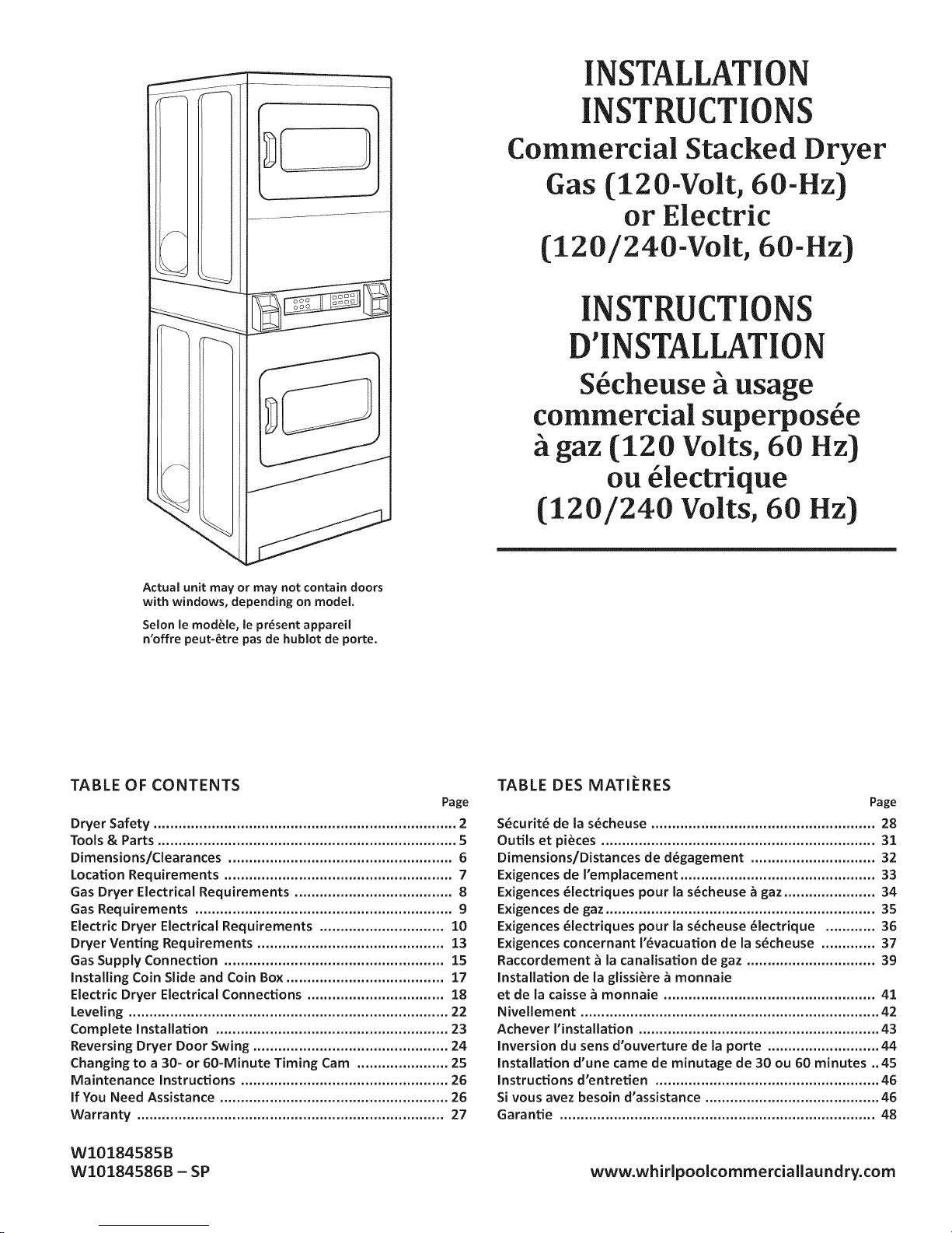
Commercial Stacked Dryer
Gas (120-Volt, 60-Hz)
or Electric
(120/240-Volt, 60-Hz)
INSTRUCTIONS
D'INSTALLATION
S6cheuse ii usage
commercial superpos6e
it gaz (120 Volts, 60 Hz)
ou 61ectrique
(120/240 Volts, 60 Hz)
Actual unit may or may not contain doors
with windows, depending on model.
Selon le modble, le pr6sent appareil
n'offre peut-6tre pas de hublot de porte.
TABLE OF CONTENTS
Page
Dryer Safety ......................................................................... 2
Tools & Parts ........................................................................ 5
Dimensions/Cleara nces ...................................................... 6
Location Requirements ....................................................... 7
Gas Dryer Electrical Requirements ...................................... 8
Gas Requirements .............................................................. 9
Electric Dryer Electrical Requirements .............................. 10
Dryer Venting Requirements ............................................. 13
Gas Supply Connection ..................................................... 15
Installing Coin Slide and Coin Box ...................................... 17
ElectricDryerElectricalConnections .................................18
Leveling ............................................................................. 22
Complete Installation ........................................................ 23
Reversing Dryer Door Swing ............................................... 24
Changing to a 30- or 60-Minute Timing Cam ...................... 25
Maintenance Instructions .................................................. 26
if You Need Assistance ....................................................... 26
Warranty .......................................................................... 27
TABLE DES MATI_:RES
Page
S6curit6de las6cheuse ...................................................... 28
Outilset pi_ces..................................................................31
Dimensions/Distances de d6gagement .............................. 32
Exigences de I'emptacement ............................................... 33
Exigences 61ectriques pour la s6cheuse _ gaz ...................... 34
Exigences de gaz ................................................................. 35
Exigences 6tectriques pour la s6cheuse 61ectrique ............ 36
Exigences concernant 1'6vacuation de la s6cheuse ............. 37
Raccordement _ la canalisation de gaz ............................... 39
Installation de la glissi_re _ monnaie
etde lacaisse_ monnaie ...................................................41
Nivellement ........................................................................ 42
Achever I'installation .......................................................... 43
inversion du sens d'ouverture de la porte ........................... 44
installation d'une came de minutage de 30 ou 60 minutes .. 45
Instructions d'entretien ...................................................... 46
SI vous avez besoin d'assistance .......................................... 46
Garantie ............................................................................ 48
WI0184585B
WI0184586B - SP
www.whirlpoolcommerciallaundry.com
DRYERSAFETY
Your safety and the safety of others are very important,
We have provided many important safety messages in this manual and on your appliance. Always read and obey all safety
messages.
This symbol alerts you to potential hazards that can kill or hurt you and others.
All safety messages will follow the safety alert symbol and either the word "DANGER" or "WARNING."
This is the safety alert symbol.
__ These words mean:
You can be killed or seriously injured if you don't immediatel v
follow instructions.
You can be killed or seriously injured if you don't follow
instructions.
All safety messages will tell you what the potential hazard is,tell you how to reduce the chance of injury, and tell you what can
happen if the instructions are not followed.
N|I lG - ...i.kofFi,o..
- Clothes dryer installation must be performed by a qualified installer.
- Install the clothes dryer according to the manufacturer's instructions and local codes.
- Do not install a clothes dryer with flexible plastic venting materials or flexible metal
(foil type) duct. if flexible metal duct is installed, it must be of a specific type identified
by the appliance manufacturer as suitable for use with clothes dryers. Flexible venting
materials are known to collapse, be easily crushed, and trap lint. These conditions will
obstruct clothes dryer airflow and increase the risk of fire.
- To reduce the risk of severe injury or death, follow all installation instructions.
- Save these instructions.
[] It is recommended that the owner post, in a prominent location, instructions for the customer's use in the event the customer
smells gas. This information should be obtained from your gas supplier.
[] Post the following warning in a prominent location.
Do not store or use gasoline or other flammable vapors and liquids in the vicinity of this or any other appliance.
FOR YOUR SAFETY
i
DRYERSAFETY
WARNING: For your safety, the information in this manual must be followed to minimize I
the risk of fire or explosion, or to prevent property damage, personal injury, or death, j
- Do not store or use gasoline or other flammable vapors and liquids in the vicinity of this
or any other appliance.
- WHAT TO DO iF YOU SMELL GAS:
= Do not try to light any appliance.
• Do not touch any electrical switch; do not use any phone in your building.
• Clear the room, building, or area of all occupants.
o Immediately carl your gas supplier from a neighbor's phone. Follow the gas supplier's
instructions.
• if you cannot reach your gas supplier, carl the fire department.
- Installation and service must be performed by a qualified installer, service agency, or
the gas supplier.
WARNING: Gas leaks cannot always be detected by smell.
Gas suppliers recommend that you use a gas detector approved by UL or CSA.
For more information, contact your gas supplier.
If a gas leak is detected, follow the "What to do if you smell gas" instructions.
in the State of Massachusetts, the following installation instructions apply:
[] Installationsand repairs must be performed by a qualified or licensed contractor, plumber, or gasfitter qualified or licensed by
the State of Massachusetts.
[] if using a ball valve, it shall be a T-handle type.
[] A flexible gas connector, when used, must not exceed 3 feet.
IMPORTANT: The gas installation must conform with local codes, or in the absence of local codes, with the National Fuel Gas
Code, ANSI Z223.1/NFPA 54 or the Canadian Natural Gas and Propane Installation Code, CSA B149.1.
The dryer must be electrically grounded in accordance with local codes, or inthe absence of local codes, with the National
Electrical Code, ANSIiNFPA 70 or Canadian Electrical Code, CSA C22.1.
I IMPORTANT: When discarding or storing your old clothes dryer, remove the door.
DRYERSAFETY
iMPORTANT SAFETYiNSTRUCTiONS
WARNING: To reduce the risk of fire, electric shock, or injury to persons when using the dryer, follow basic precautions,
including the following:
[] Read all instructions before using the dryer.
[] This dryer is intended only for drying clothes and textiles
that have been washed in water. Do not use for any
other purpose.
[] WARNING: If you smell gas, do not use the dryer or any
electrical equipment nearby. Warn other people to clear
the area. Contact the dryer owner immediately.
[] Do not place items exposed to cooking oils in your dryer.
Items contaminated with cooking oils may contribute to
a chemical reaction that could cause a load to catch fire.
[] Do not dry articles that have been previously cleaned
in, washed in, soaked in, or spotted with gasoline,
dry-cleaning solvents, other flammable, or explosive
substances as they give off vapors that could ignite
or explode.
[] Do not dry unwashed items in the dryer.
[] Do not allow children to play on or in the dryer. Close
supervision of children is necessary when the dryer is
used near children.
[] Before the dryer is removed from service or discarded,
remove the doors to the dryer compartment.
[] Do not reach into the dryer if the drum is moving.
[] Do not open door while dryer is in operation. It will stop.
[] Do not install or store the dryer where it will be exposed
to the weather.
[] Do not tamper with controls.
[] Clean dryer lint screen before or after each load.
[] Do not use this dryer without the lint screen in place.
[] Do not repair or replace any part of the dryer or attempt
any servicing unless specifically recommended in this
Installation Instructions or in published user-repair
instructions that you understand and have the skills
to carry out.
[] Do not use fabric softeners or products to eliminate static
unless recommended by the manufacturer of the fabric
softener or product.
[] Do not use heat to dry articles containing foam rubber or
similarly textured rubber-like materials.
[] The final part of a tumble dryer cycle occurs without heat
(cool-down cycle) to ensure that the articles are left at
a temperature that ensures that the items will not be
damaged.
[] WARNING: Never stop a tumble dryer before the end of
the drying cycle unless all items are quickly removed and
spread out so that the heat is dissipated. (Avoids risk of
spontaneous combustion).
[] Keep area around the exhaust opening and adjacent
surrounding areas free from the accumulation of lint,
dust, and dirt.
[] The interior of the dryer and dryer exhaust vent should
be cleaned periodically by qualified service personnel.
[] See "Electrical Requirements" section for grounding
instructions.
SAVETHESE INSTRUCTIONS
4
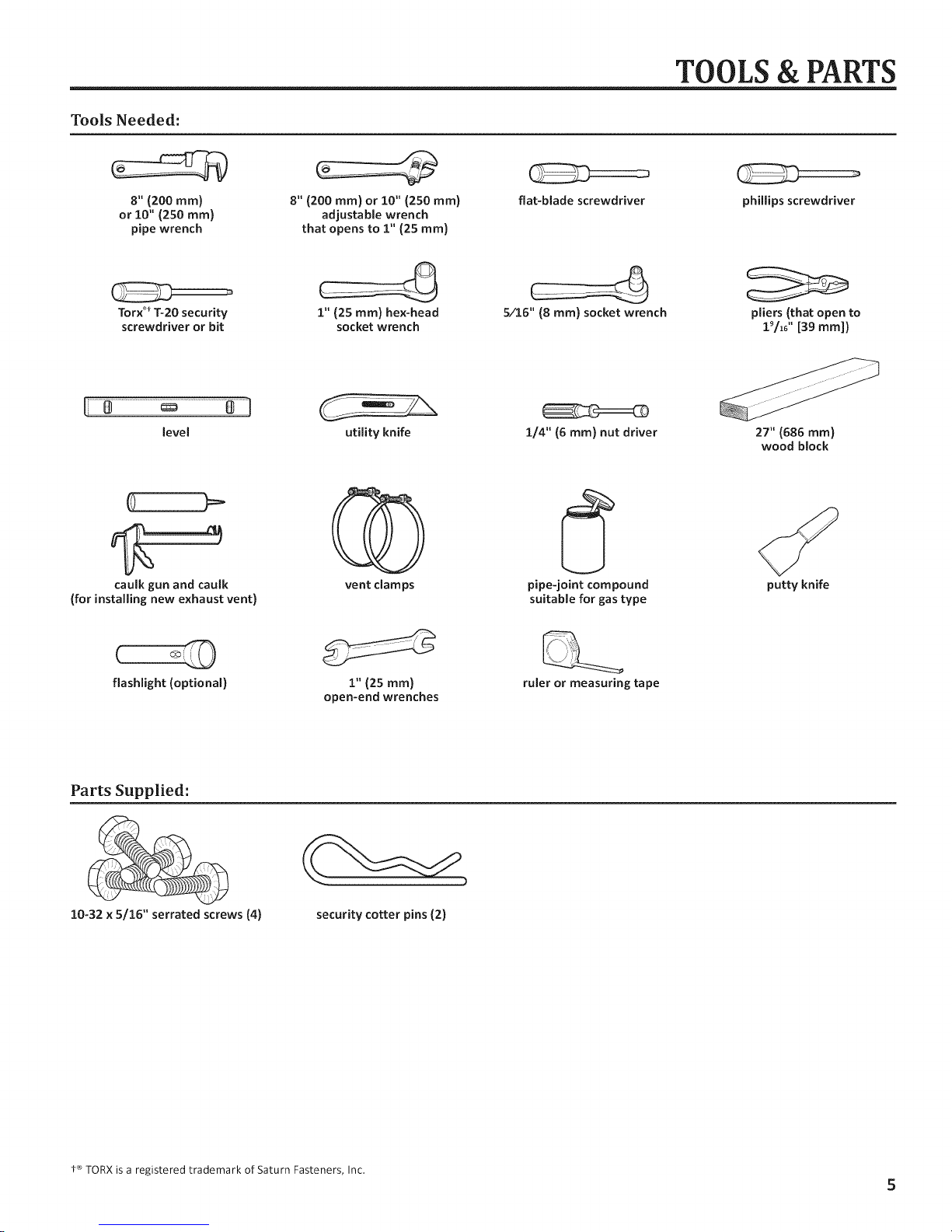
Tools Needed:
TOOLS & PARTS
8"(200 ram)
or 10" (250 ram)
pipe wrench
Torx _'*1"-20 security
screwdriver or bit
level
caulk gun and caulk vent clamps pipe-joint compound putty knife
(for installing new exhaust vent) suitable for gas type
8" (200 ram) or 10" (250 ram)
adjustable wrench
that opens to 1" (25 ram}
1" (25 ram) hex-head
socket wrench
utility knife i/4" (6 ram) nut driver 27" (686 ram)
flat-blade screwdriver
5/16"(8 ram)socketwrench pliers (that open to
phillips screwdriver
19/i_'' [39 mini)
wood block
flashlight (optional) i"(25ram)
Parts Supplied:
10-32 x 5/16" serrated screws (4)
security cotter pins (2)
open-end wrenches
ruler or measuring tape
t <"_TORXis a registered trademark of Saturn Fasteners, Inc.
5
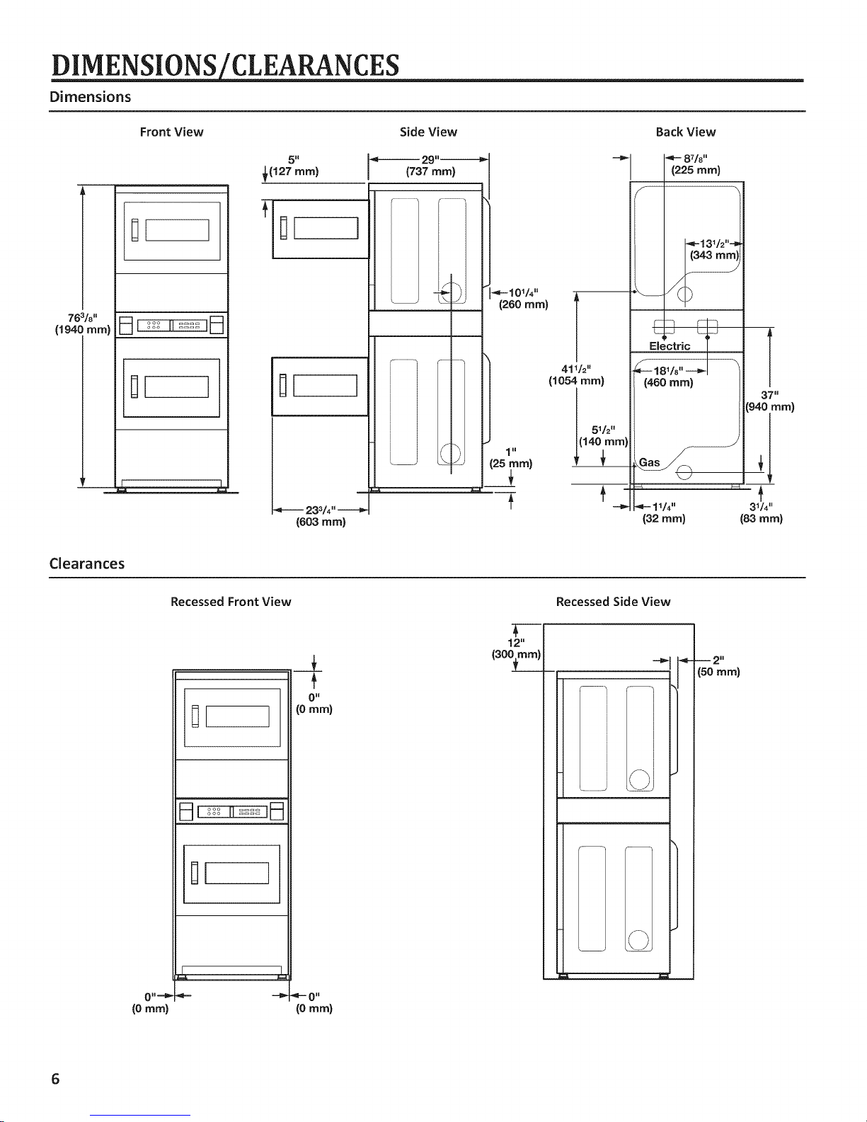
_CLEARANCES
Dimensions
763/8''
(194C mm}
Front View
1[ 1
1[ ]
Side View
€(127 ram) I (737 ram)
1
233/4"
(603 ram)
Back View
8T/8,,
(225 mini
f
Electric
41V2"
(1054 ram)
51/2"
1 ii
181/8"
(460 mm)
37"
(940 ram)
[
_-- 11/4" 31/4''
(32 ram) (83 ram)
Clearances
Recessed Front View
II ]
__L
O"
(0 ram}
€
12"
(300from)
Recessed Side View
m
(50 ram)
m 2 n
Explosion Hazard
Keep flammable materials and vapors, such as
gasoline, away from dryer.
Do not install in a garage.
Failure to do so can result in death, explosion, or fire.
Your dryer can be installed in a basement, laundry room, or
recessed area.
Companion appliance location requirements should also be
considered.
iMPORTANT:
[] Do not install or store the dryer where it will be exposed to
the weather. Proper installation is your responsibility.
[] This dryer must not be installed in a closet with a door.
You will need:
[] A grounded electrical outlet located within 6 ft. (1.8 m) of
where the power cord is attached to the back of the dryer.
See "Electrical Requirements."
[] A level floor with a maximum slope of 1" (25 mm) under
entire dryer. Installing the dryer on soft floor surfaces,
such as carpets or surfaces with foam backing, is not
recommended.
Dryer installation clearances
[] The location must be large enough to allow the dryer door
to be fully opened.
[] Additional spacing should be considered for ease of
installation and servicing. The door opens more than 180 °.
[] Additional clearances might be required for wall, door, and
floor moldings.
[] Additional spacing of I" (25 ram) on all sides of the dryer is
recommended to reduce noise transfer.
When installing a gas dryer:
iMPORTANT: Observe all governing codes and ordinances.
[] Check code requirements: Some codes limit or do not
permit installation of clothes dryers in garages, closets, or
sleeping quarters. Contact your local building inspector.
[] Make sure that lower edges of the cabinet, plus the back
and bottom sides of the dryer, are free of obstructions to
permit adequate clearance of air openings for combustion
air. See "Recessed Area Installation Instructions" below for
minimum spacing requirements.
LOCATION REQUIREMENTS
Recessed Area Installation Instructions
This dryer may be installed in a recessed area. For recessed
area installations, minimum clearances can be found on the
warning label on the rear of the dryer or in "Dimensions/
Clearances."
The installation spacing is in inches and is the minimum
allowable. Additional spacing should be considered for ease
of installation, servicing, and compliance with local codes and
ordinances.
The dryer must be exhausted outdoors.
GAS DRYER ELECTRICAL RE UIREMENTS
Gas Dryer Grounding
GROUNDING INSTRUCTIONS
[] For a grounded, cord-connected dryer:
This dryer must be grounded. In the event of malfunction or
breakdown, grounding will reduce the risk of electric shock
by providing a path of least resistance for electric current.
Electrical Shock Hazard
Plug into a grounded 3 prong outlet.
Do not remove ground prong.
Do not use an adapter.
Do not use an extension cord.
Failure to follow these instructions can result in death,
fire, or electrical shock.
iMPORTANT: The dryer must be electrically grounded in
accordance with local codes and ordinances or, in the absence
of local codes, with the National Electrical Code, ANSI/NFPA 70,
latest edition, or Canadian Electrical Code, CSAC22.1. If codes
permit and a separate ground wire is used, it is recommended
that a qualified electrical installer determine that the ground
path isadequate.
A copy of the above code standards can be obtained from:
National Fire Protection Association
One Batterymarch Park, Quincy, MA 02269
CSAInternational
8501 East Pleasant Valley Road
Cleveland, Ohio 44131-5575
[] Do not ground to a gas pipe.
[] Do not have a fuse inthe neutral or ground circuit.
[] A 120 volt, 60 Hz, AC only, 15- or 20-amp, fused electrical
circuit is required. A time-delay fuse or circuit breaker is
also recommended. It is recommended that a separate
circuit serving only this dryer be provided.
[] If codes permit and a separate ground wire isused, it is
recommended that a qualified electrician determine that
the ground path is adequate.
[] Check with a qualified electrician if you are not sure the
dryer is properly grounded.
This dryer uses a cord having an equipment-grounding
conductor and a grounding plug. The plug must be plugged
into an appropriate outlet that is properly installed and
grounded in accordance with all local codes and ordinances.
[] For a permanently connected dryer:
This dryer must be connected to a grounded metal,
permanent wiring system, or an equipment-grounding
conductor must be run with the circuit conductors and
connected to the equipment-grounding terminal or lead on
the dryer.
WARNING: Improper connection of the equipment-
grounding conductor can result in a risk of electric shock.
Check with a qualified electrician or service representative
or personnel if you are in doubt as to whether the dryer is
properly grounded. Do not modify the plug on the power
supply cord: if it will not fit the outlet, have a proper outlet
installed by a qualified electrician.
SAVE THESE INSTRUCTIONS
Gas Supply
Explosion Hazard
Use a new CSA international approved gas supply line.
|nstall a shut=off valve,
Securely tighten all gas connections.
if connected to LP, have a qualified person make sure
gas pressure does not exceed 13" (330 ram) water
column.
Examples of a qualified person include:
|icensed heating personnel,
authorized gas company personnel, and
authorized service personnel.
Failure to do so can result in death, explosion, or fire.
IMPORTANT: Observe all governing codes and ordinances.
This installation must conform with all local codes and
ordinances. In the absence of local codes, installation must
conform with American National Standard, National Fuel Gas
Code ANSI Z223.1/NFPA 54 or CAN/CSA B149.
A copy of the above code standards can be obtained from:
National Fire Protection Association
One Batterymarch Park, Quincy, MA 02269
CSA International
8501 East Pleasant Valley Road
Cleveland, Ohio 44131-5575
The design of this dryer has been certified by CSA International
for use at altitudes up to 10,000 feet (3048 m) above sea level
at the B.T.U. rating indicated on the model/serial plate. Burner
input adjustments are not required when the dryer is operated
up to this elevation.
When installed above 10,000 feet (3048 m), a four percent
(4%) reduction of the burner B.T.U. rating shown on the model/
serial plate is required for each 1,000 foot (305 m) increase in
elevation. For assistance when converting to other gas types
and/or installing above 10,000 feet (3048 m) elevation, contact
your local service company.
ELECTRIC DRYERELECTRICAL REQUIREMENTS
(U.S.A. ONLY) (ETATS-UNIS SEULEMENT)
It is your responsibility:
[] To contact a qualified electrical installer.
[] To be sure that the electrical connection is adequate and in
conformance with the National Electrical Code, ANSI/NFPA
70-latest edition and all local codes and ordinances.
[]
The National Electrical Code requires a 4-wire power
supply connection for homes built after 1996, dryer circuits
involved in remodeling after 1996, and all mobile home
installations.
[]
A copy of the above code standards can be obtained from:
National Fire Protection Association, One Batterymarch
Park, Quincy, MA 02269.
[]
To supply the required 3 or 4 wire, single phase, 120/240
volt, 60 Hz., AC only electrical supply (or 3 or 4 wire,
120/208 volt electrical supply, if specified on the serial/
rating plate) on a separate 30-amp circuit, fused on both
sides of the line. A time delay fuse or circuit breaker is
recommended. Connect to an individual branch circuit.
Do not have a fuse in the neutral or grounding circuit.
[]
Do not use an extension cord.
[]
If codes permit and a separate ground wire is used, it is
recommended that a qualified electrician determine that
the ground path is adequate.
Electrical Connection
To properly install your dryer, you must determine the type
of electrical connection you will be using and follow the
instructions provided for it here.
[] This dryer is manufactured ready to install with a 3-wire
electrical supply connection. The neutral ground conductor
is permanently connected to the neutral conductor (white
wire) within the dryer. If the dryer is installed with a 4-wire
electrical supply connection, the neutral ground conductor
must be removed from the external ground connector
(green screw), and secured under the neutral terminal
(center or white wire) of the terminal block. When the
neutral ground conductor is secured under the neutral
terminal (center or white wire) of the terminal block, the
dryer cabinet is isolated from the neutral conductor.
[] If local codes do not permit the connection of a neutral
ground wire to the neutral wire, see "Optional 3-wire
connection" section.
[]
A 4-wire power supply connection must be used when the
appliance is installed in a location where grounding through
the neutral conductor is prohibited. Grounding through the
neutral is prohibited for (1) new branch-circuit installations
and (2) areas where local codes prohibit grounding through
the neutral conductor.
Electric Dryer Grounding
GROUNDING INSTRUCTIONS
[] For a grounded, cord-connected dryer:
This dryer must be grounded. In the event of malfunction or
breakdown, grounding will reduce the risk of electric shock
by providing a path of least resistance for electric current.
This dryer uses a cord having an equipment-grounding
conductor and a grounding plug. The plug must be plugged
into an appropriate outlet that is properly installed and
grounded in accordance with all local codes and ordinances.
[] For a permanently connected dryer:
This dryer must be connected to a grounded metal,
permanent wiring system, or an equipment-grounding
conductor must be run with the circuit conductors and
connected to the equipment-grounding terminal or lead on
the dryer.
WARNING: Improper connection of the equipment-
grounding conductor can result in a risk of electric shock.
Check with a qualified electrician or service representative
or personnel if you are in doubt as to whether the dryer is
properly grounded. Do not modify the plug on the power
supply cord: if it will not fit the outlet, have a proper outlet
installed by a qualified electrician.
SAVE THESE INSTRUCTIONS
10
ELECTRIC DRYERELECTRICAL REQUIREMENTS
(U.S.A. ONLY) (ETATS-UNIS SEULEMENT)
Electric Dryer Power Supply Cord
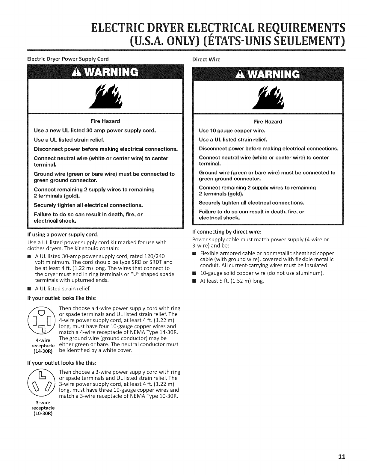
Fire Hazard
Use a new UL listed 30 amp power supply cord.
Use a UL listed strain relief.
Disconnect power before making electrical connections.
Connect neutral wire (white or center wire) to center
terminal.
Ground wire (green or bare wire) must be connected to
green ground connector.
Connect remaining 2 supply wires to remaining
2 terminals (gold).
Securely tighten ag electrical connections.
Failure to do so can result in death, fire, or
electrical shock.
If using a power supply cord:
Use a UL listed power supply cord kit marked for use with
clothes dryers. The kit should contain:
[] A UL listed 30-amp power supply cord, rated 120/240
volt minimum. The cord should be type SRDor SRDTand
be at least 4 ft. (1.22 m) long. The wires that connect to
the dryer must end in ring terminals or "U" shaped spade
terminals with upturned ends.
[] A UL listed strain relief.
If your outlet looks like this:
Then choose a 4-wire power supply cord with ring
or spade terminals and UL listed strain relief. The
4-wire power supply cord, at least 4 ft. (1.22 m)
long, must have four lO-gauge copper wires and
match a 4-wire receptacle of NEMA Type 14-30R.
4-wire
receptacle
(14-30R}
The ground wire (ground conductor) may be
either green or bare. The neutral conductor must
be identified by a white coven
Direct Wire
Fire Hazard
Use 10 gauge copper wire.
Use a UL listed strain relief.
Disconnect power before making electrical connections.
Connect neutral wire (white or center wire) to center
terminal
Ground wire (green or bare wire) must be connected to
green ground connector.
Connect remaining 2 supply wires to remaining
2 terminals (gold}.
Securely tighten all electrical connections.
Failure to do so can result in death, fire, or
electrical shock.
If connecting by direct wire:
Power supply cable must match power supply (4-wire or
3-wire) and be:
[] Flexible armored cable or nonmetallic sheathed copper
cable (with ground wire), covered with flexible metallic
conduit. All current-carrying wires must be insulated.
[] 10-gauge solid copper wire (do not use aluminum).
[] At least 5 ft. (1.52 m) long.
If your outlet looks like this:
Then choose a 3-wire power supply cord with ring
or spade terminals and UL listed strain relief. The
3-wire power supply cord, at least 4 ft. (1.22 m)
long, must have three 10-gauge copper wires and
match a 3-wire receptacle of NEMA Type 10-30R.
3-wire
receptacle
(I0-30R}
11
ELECTRIC DRYERELECTRICAL REQUIREMENTS
(CANADA ONLY) (LE CANADA SEULEMENT)
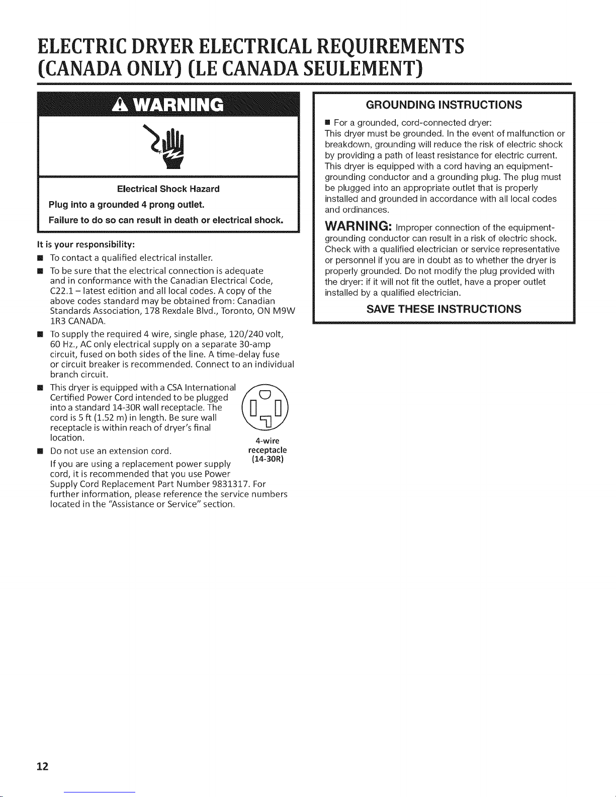
GROUNDING INSTRUCTIONS
m For a grounded, cord-connected dryer:
This dryer must be grounded. In the event of malfunction or
breakdown, grounding will reduce the risk of electric shock
by providing a path of least resistance for electric current.
This dryer is equipped with a cord having an equipment-
grounding conductor and a grounding plug. The plug must
Electrical Shock Hazard
Plug into a grounded 4 prong outlet.
Failure to do so can result in death or electrical shock.
It is your responsibility:
[] To contact a qualified electrical installer.
[] To be sure that the electrical connection is adequate
and in conformance with the Canadian Electrical Code,
C22.1 - latest edition and all local codes. A copy of the
above codes standard may be obtained from: Canadian
Standards Association, 178 Rexdale Blvd., Toronto, ON M9W
1R3 CANADA.
[] To supply the required 4 wire, single phase, 120/240 volt,
60 Hz., AC only electrical supply on a separate 30-amp
circuit, fused on both sides of the line. A time-delay fuse
or circuit breaker isrecommended. Connect to an individual
branch circuit.
[] This dryer is equipped with a CSA International
Certified Power Cord intended to be plugged
into a standard 14-30R wall receptacle. The
cord is 5 ft (1.52 m) in length. Be sure wall
receptacle is within reach of dryer's final
location.
[] Do not use an extension cord.
If you are using a replacement power supply
cord, it is recommended that you use Power
Supply Cord Replacement Part Number 9831317. For
further information, please reference the service numbers
located in the "Assistance or Service" section.
4-wire
receptacle
(14-30R}
be plugged into an appropriate outlet that is properly
installed and grounded in accordance with all local codes
and ordinances.
WARNING: Improper connection of the equipment-
grounding conductor can result in a risk of electric shock.
Check with a qualified electrician or service representative
or personnel if you are in doubt as to whether the dryer is
properly grounded. Do not modify the plug provided with
the dryer: if it will not fit the outlet, have a proper outlet
installed by a qualified electrician.
SAVE THESE INSTRUCTIONS
12
DRYERVENTING REQUIREMENTS
Fire Hazard
Use a heavy metal vent,
Do not use a plastic vent.
Do not use a metal foil vent.
Failure to folow these instructions can result in death
or fire,
WARNING: To reduce the risk of fire, this dryer MUST BE
EXHAUSTED OUTDOORS.
IMPORTANT: Observe all governing codes and ordinances.
Dryer exhaust must not be connected into any gas vent,
chimney, wall, ceiling, attic, crawlspace, or a concealed space
of a building. Only rigid or flexible metal vent shall be used for
exhausting.
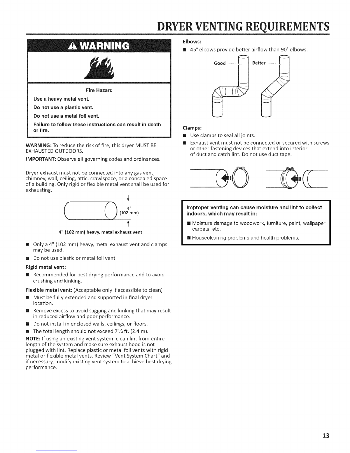
Elbows:
[] 45 ° elbows provide better airflow than 90° elbows.
................. Bet
Clamps:
[] Use clamps to seal all joints.
[] Exhaust vent must not be connected or secured with screws
or other fastening devices that extend into interior
of duct and catch lint. Do not use duct tape.
(102 ram)
T
4" (102 mm) heavy, metal exhaust vent
[] Only a 4" (102 mm) heavy, metal exhaust vent and clamps
may be used.
[] Do not use plastic or metal foil vent.
Rigid metal vent:
[] Recommended for best drying performance and to avoid
crushing and kinking.
Flexible metal vent: (Acceptable only if accessible to clean)
[] Must be fully extended and supported in final dryer
location.
[] Remove excess to avoid sagging and kinking that may result
in reduced airflow and poor performance.
[] Do not install in enclosed walls, ceilings, or floors.
[] The total length should not exceed 73/4ft. (2.4 m).
NOTE: If using an existing vent system, clean lint from entire
length of the system and make sure exhaust hood is not
plugged with lint. Replace plastic or metal foil vents with rigid
metal or flexible metal vents. Review "Vent System Chart" and
if necessary, modify existing vent system to achieve best drying
performance.
Improper venting can cause moisture and lint to collect
indoors, which may result in:
[] Moisture damage to woodwork, furniture, paint, wallpaper,
carpets, etc.
[] Housecleaning problems and health problems.
13
DRYERVENTING REQUIREMENTS
Vent Hoods
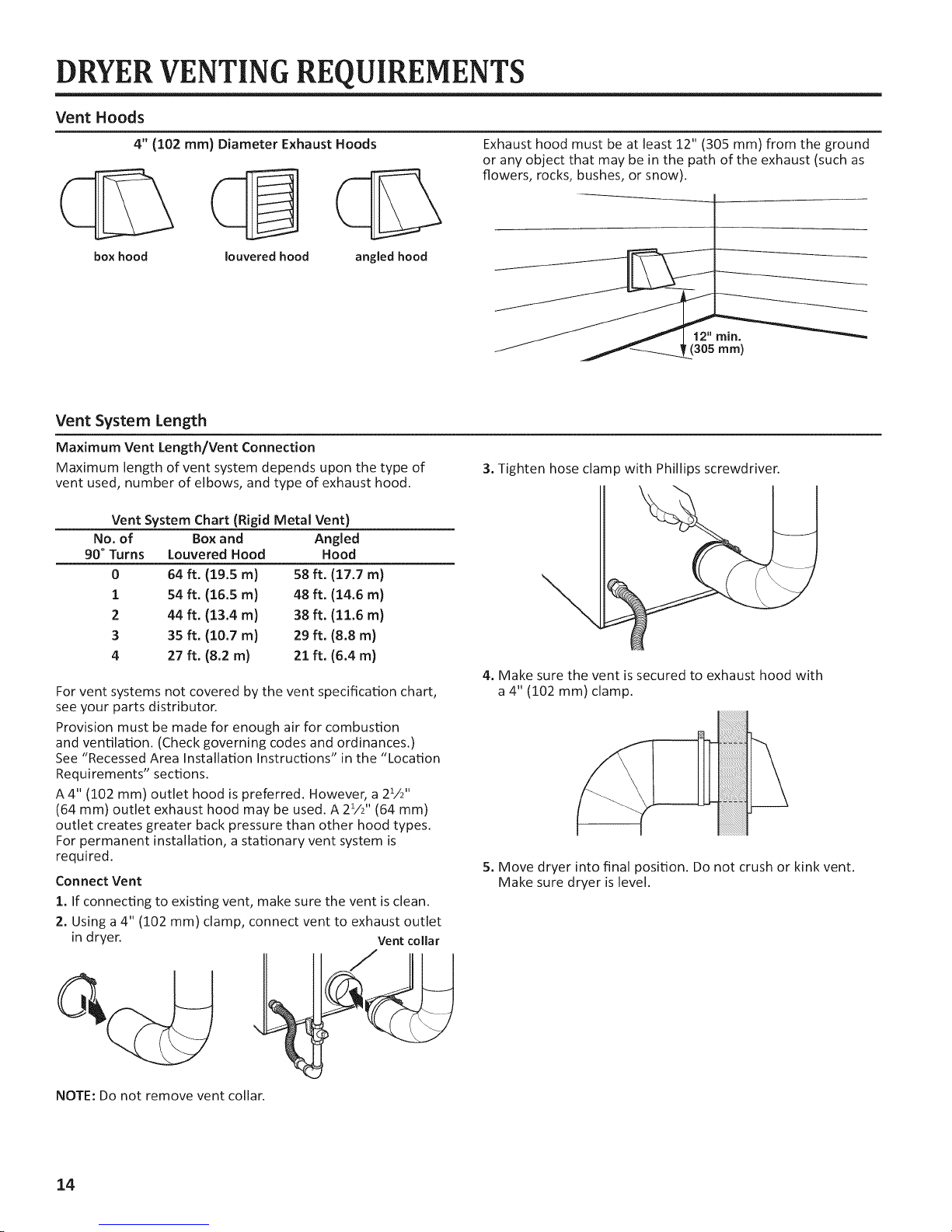
4" (102 mm) Diameter Exhaust Hoods
box hood louvered hood angled hood
Vent System Length
Maximum Vent Length/Vent Connection
Maximum length of vent system depends upon the type of
vent used, number of elbows, and type of exhaust hood.
Vent System Chart (Rigid Metal Vent)
No. of Box and Angled
90° Turns Louvered Hood Hood
0 64 ft. (19.5 m) 58 ft. (17.7 m)
1 54 ft. (16.5 m) 48 ft. (14.6 m)
2 44 ft. (13.4 m) 38 ft. (11.6 m)
3 35 ft. (10.7 m) 29 ft. (8.8 m)
4 27 ft. (8.2 m) 21 ft. (6.4 m)
For vent systems not covered by the vent specification chart,
see your parts distributor.
Provision must be made for enough air for combustion
and ventilation. (Check governing codes and ordinances.)
See "Recessed Area Installation Instructions" in the "Location
Requirements" sections.
A 4" (102 mm) outlet hood is preferred. However, a 21/2''
(64 mm) outlet exhaust hood may be used. A 23/2 '' (64 mm)
outlet creates greater back pressure than other hood types.
For permanent installation, a stationary vent system is
required.
Connect Vent
1. If connecting to existing vent, make sure the vent isclean.
2. Using a 4" (102 mm) clamp, connect vent to exhaust outlet
in dryer.
Vent collar
Exhaust hood must be at least 12" (305 mm) from the ground
or any object that may be in the path of the exhaust (such as
flowers, rocks, bushes, or snow).
3. Tighten hose clamp with Phillips screwdriver.
4. Make sure the vent is secured to exhaust hood with
a 4" (102 mm) clamp.
5. Move dryer into final position. Do not crush or kink vent.
Make sure dryer is level.
NOTE: Do not remove vent collar.
14
DRYERVENTING REQUIREMENTS
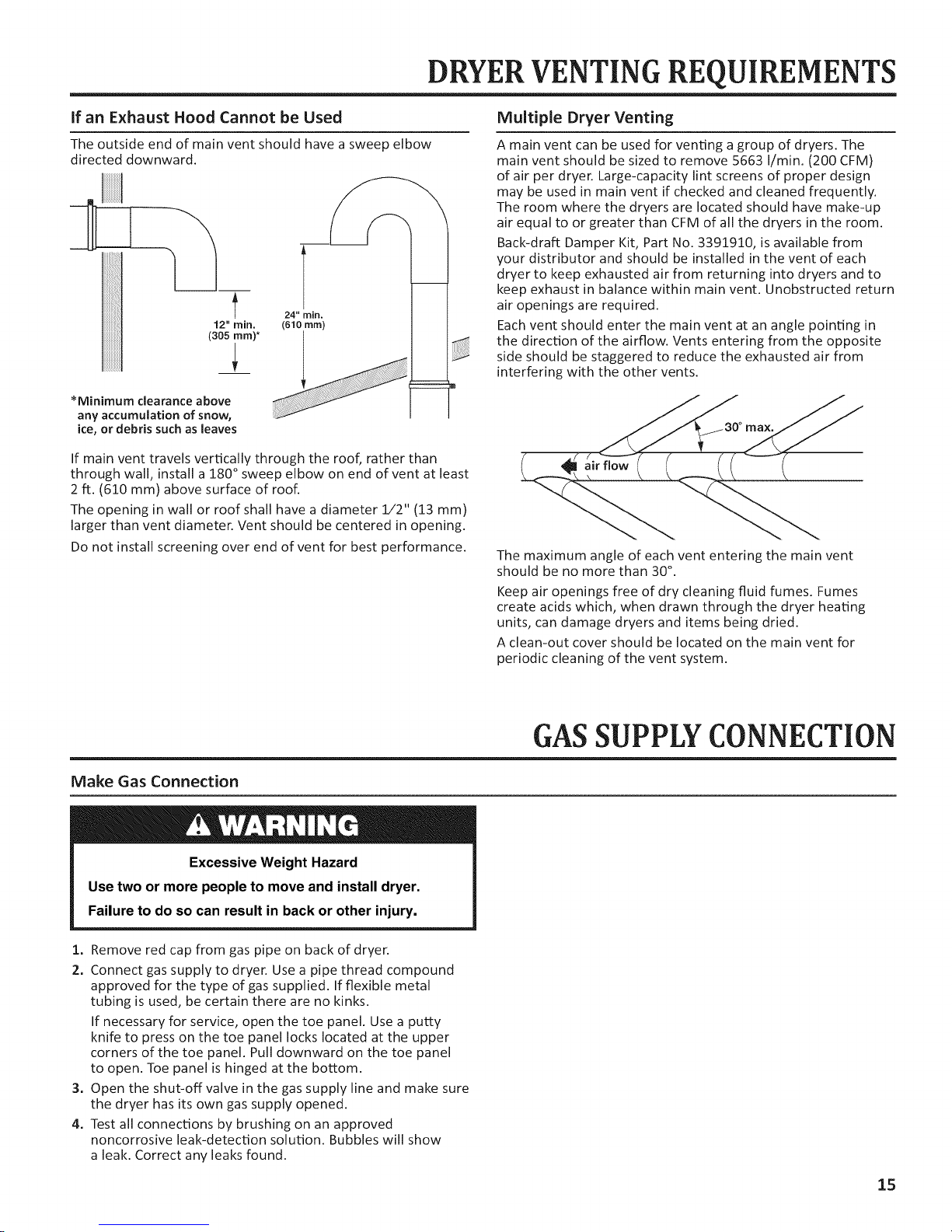
If an Exhaust Hood Cannot be Used
The outside end of main vent should have a sweep elbow
directed downward.
I__
12" rnin.
(305 ram)*
*Minimum clearance above
any accumulation of snow,
ice, or debris such as leaves
24" rain.
(610 ram)
If main vent travels vertically through the roof, rather than
through wall, install a 180 ° sweep elbow on end of vent at least
2 ft. (610 mm) above surface of roof.
The opening in wall or roof shall have a diameter 1/2" (13 mm)
larger than vent diameter. Vent should be centered in opening.
Do not install screening over end of vent for best performance.
Multiple Dryer Venting
A main vent can be used for venting a group of dryers. The
main vent should be sized to remove 5663 I/rain. (200 CFM)
of air per dryer. Large-capacity lint screens of proper design
may be used in main vent if checked and cleaned frequently.
The room where the dryers are located should have make-up
air equal to or greater than CFM of all the dryers in the room.
Back-draft Damper Kit, Part No. 3391910, is available from
your distributor and should be installed in the vent of each
dryer to keep exhausted air from returning into dryers and to
keep exhaust in balance within main vent. Unobstructed return
air openings are required.
Each vent should enter the main vent at an angle pointing in
the direction of the airflow. Vents entering from the opposite
side should be staggered to reduce the exhausted air from
interfering with the other vents.
The maximum angle of each vent entering the main vent
should be no more than 30°.
Keep air openings free of dry cleaning fluid fumes. Fumes
create acids which, when drawn through the dryer heating
units, can damage dryers and items being dried.
A clean-out cover should be located on the main vent for
periodic cleaning of the vent system.
Make Gas Connection
Excessive Weight Hazard
Use two or more people to move and install dryer.
Failure to do so can result in back or other injury.
1. Remove red cap from gas pipe on back of dryer.
2. Connect gas supply to dryer. Use a pipe thread compound
approved for the type of gas supplied. If flexible metal
tubing is used, be certain there are no kinks.
If necessary for service, open the toe panel. Use a putty
knife to press on the toe panel locks located at the upper
corners of the toe panel. Pull downward on the toe panel
to open. Toe panel is hinged at the bottom.
3. Open the shut-off valve in the gas supply line and make sure
the dryer has its own gas supply opened.
4. Test all connections by brushing on an approved
noncorrosive leak-detection solution. Bubbles will show
a leak. Correct any leaks found.
GASSUPPLY CONNECTION
15
 Loading...