

Page 1
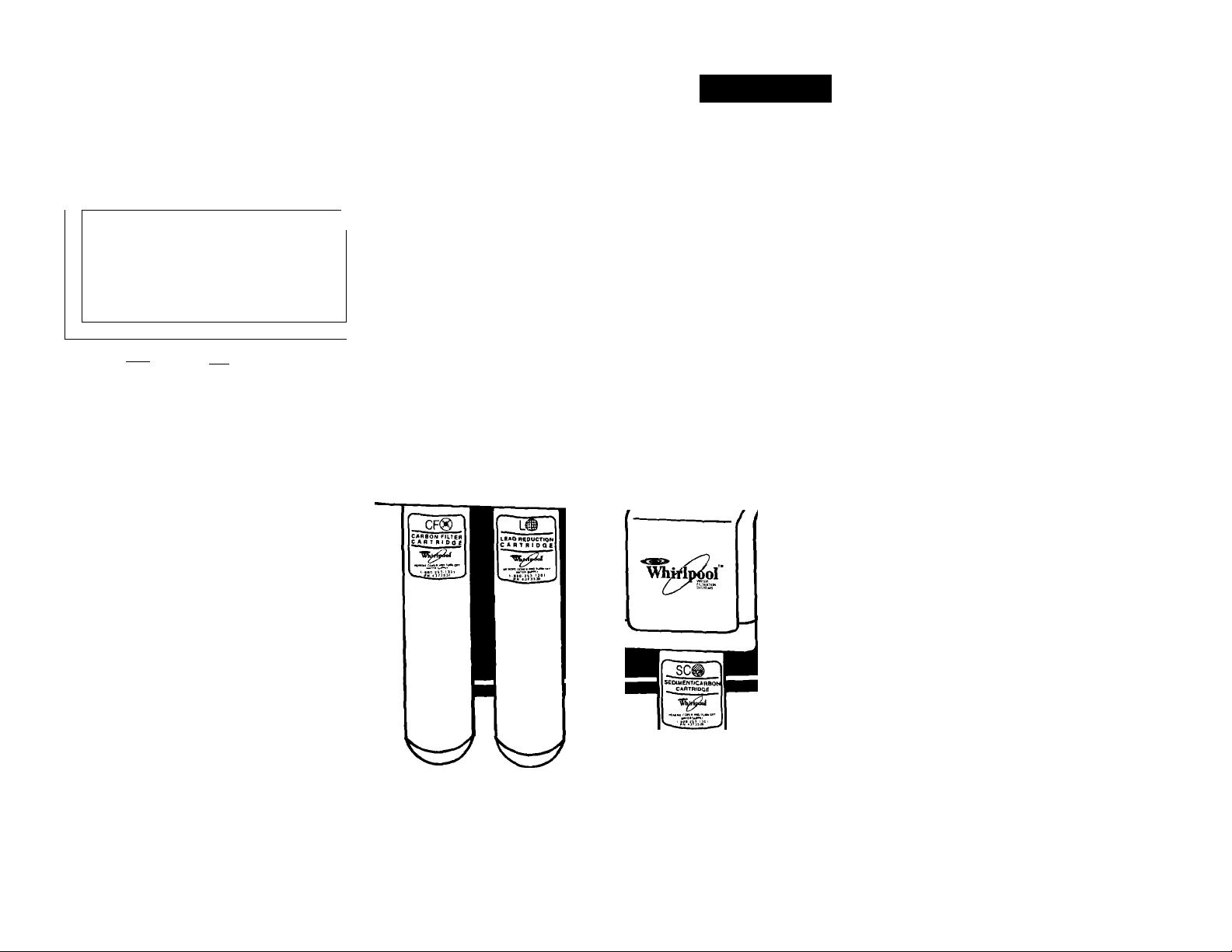
Whirlpool
fT-
^ -
CFg>
CF®
Th
k)
Use & Care
Guide and
AVhirlp<ior
Installation
Instructions
WHIRLPOOL
UNDERCOUNTER
w
WATER FILTRATION
SYSTEMS I, II, & III
Page 2
Water Filtration
System Parts
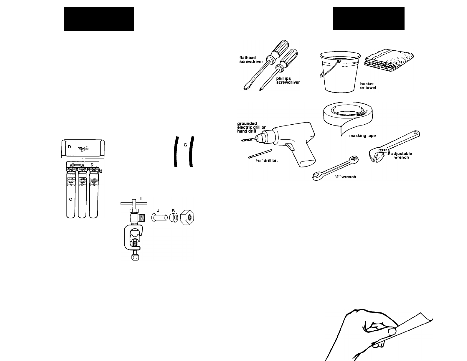
Remove parts from packages.
Check that you have all the parts.
Tools Needed
for Installation
filtration assembly System I (A)
filtration assembly System II (B)
filtration assembly System III (C)
filtration assembly cover (D)
2 mounting screws (E)
'A" blue tubing (F)
'A" orange tubing (G)
2-way grey connector with push-in ends (H)
saddle valve assembly (I)
insert (J)
plastic sleeve (K)
brass compression nut (L)
literature package
C]°E|i
D
v_y
Y
rr^9ini
w
Materials Needed for Basement Installation
• step ladder • Additional tubing,
• yv drill bit Part No. 4319151 available
• safety glasses from your Whirlpool dealer.
Materials Needed for Optional Sink Faucet Installation
Sink faucet. Part No. 4319154, available from your
Whirlpool dealer. Includes: faucet base with blue
tubing attached, assembly hardware, faucet spout,
2-way grey connector with push-in ends, and a
“T” grey connector with push-in ends.
NOTE:
Some state and local plumbing codes prohibit the use of saddle-type
valves. The use of saddle-type valves is prohibited in; Alaska,
Delaware, Idaho, Kentucky, Massachusetts, Michigan, Minnesota,
New Hampshire, North Dakota, Ohio, Oregon and South Dakota.
Check your local plumbing codes for details.
Massachusetts CMR 248 strictly prohibits the use of saddle-type
valves. The feed-water connection must conform to applicable
plumbing codes.
Open This Flap For Installation Overview
Page 3
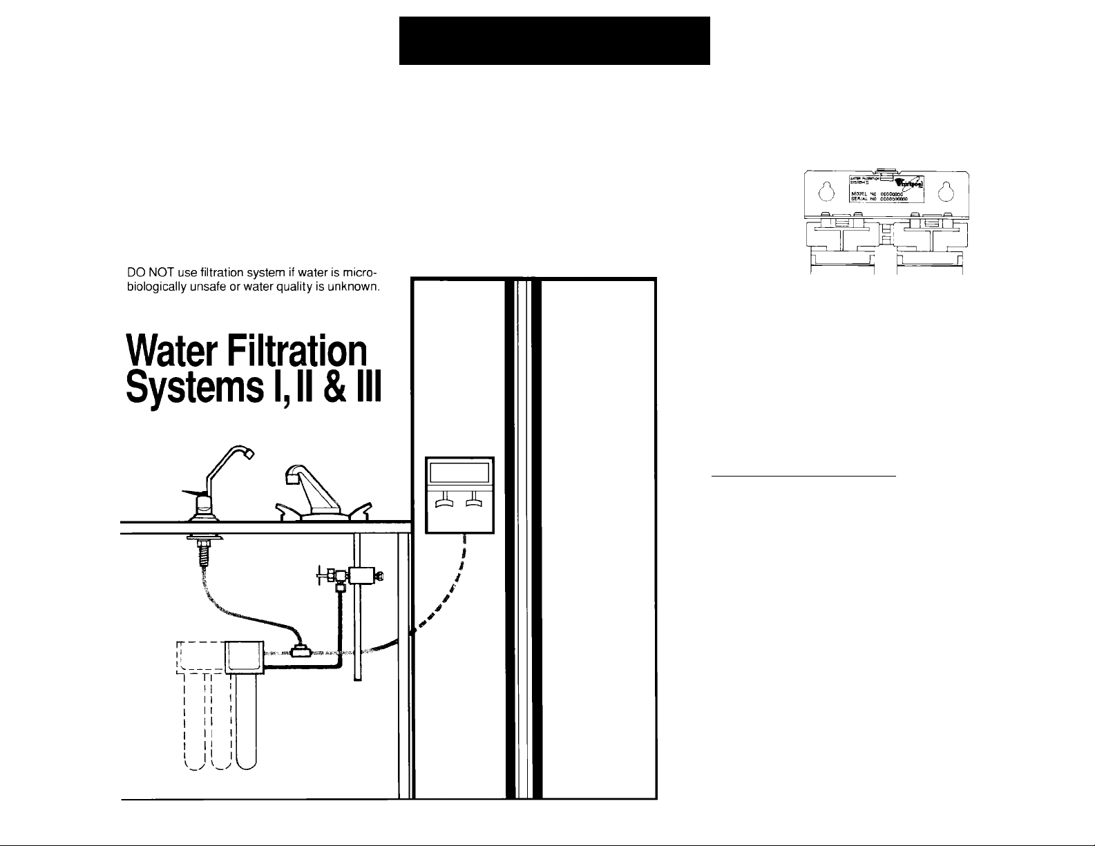
Ins ta llat io n O verv ie w
Before You Start...
IMPORTANT : Read and save these instructions.
It is recommended that this system be installed by a licensed plumber.
It is the responsibility of the installer to comply with the
installation specifications provided and with state and local
plumbing codes.
If you decided to install the system yourself, see “General
Information” on page 9 before continuing.
Water Filtration Systems I, II and III can be installed in the basement if
there is not adequate room for under-sink installation. Order additional
tubing, Part No. 4319151 from your Whirlpool dealer.
If you need assistance...
Refer to the Use & Care information at the end of this booklet. If you need more help,
the Whirlpool Consumer Assistance Center will answer any questions you may have
about operating or maintaining your water filtration system. The Whirlpool Consumer
Assistance Center is open 24 hours a day, 7 days
a week. Just dial 1-800-253-1301—the call is free.
When you call, you will need the water filtration
system model number and serial number. Both
numbers can be found labeled on the filtration
assembly.
HOOK UP WATER
(5
»Turn off cold water supply.
•Turn on faucet to drain water from line.
• Connect saddle valve to cold water supply.
Turn saddle valve handle clockwise until
piercing lance enters pipe and stops.
• Connect one end of orange tubing to
saddle valve. Connect other end to
filtration assembly.
(^ SYSTEM CONNECTION
Decide if the system will be connected
to your refrigerator, to an optional faucet
or to both.
• Connect refrigerator’s water supply to
filtration assembly with blue tubing.
• Or, install faucet in sink and connect
blue tubing to filtration assembly.
• Or, use "T” grey connector to connect
both refrigerator and faucet.
I START UP
• Slide filtration assembly onto mounting
screws.
• Turn on cold water supply.
• If filtration assembly was connected to
refrigerator, make and discard 2 batches
of ice and drain 2-3 gallons of water from
water dispenser.
• If filtration assembly was connected to
sink faucet, lift faucet handle to discard
2-3 gallons of water.
Page 4
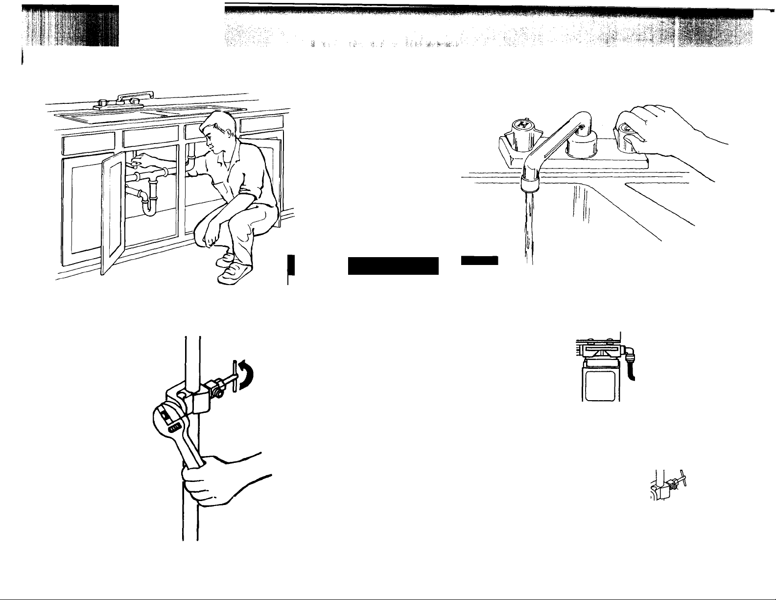
Instructions At A Glance • For detailed instructions see following page.
1. Turn off cold water supply. (Steps 1a-1b)
Special care must be taken when drilling into
water pipes. Some water may remain in water
supply pipe:
• If an electric drill is used, it must be properly
• Use only an electric drill that is double
• Check with qualified electrician if you are in
• Only drill at top or side of horizontal water
Failure to follow these instructions could result
in personal injury or death.
! WARNING
Electrical Shock Hazard
grounded to prevent severe or lethal shock if
water should enter drill.
insulated or properly grounded.
doubt as to whether your electric drill is
properly grounded.
supply pipe. DO NOT drill at bottom of
horizontal pipe where water may remain.
2. Turn on faucet to drain water from line.
(Step 1b)
3. Connect saddle valve to cold water supply. Turn saddle
valve handle clockwise until piercing lance enters
pipe and stops. (Steps Ic-lg or Ih-lj)
w
4. Connect one end of orange tubing to saddle valve.
Connect other end to filtration assembly. (Step Ik)
Page 5
! CAUTION
Product Damage
DO NOT connect to a hot water supply line.
Failure to follow this instruction could result in
product damage.
^ Q Take note of water requirements listed under
Ida the Use & Care section of this booklet. The
filtration system's feed line (orange tubing)
connects to your cold water supply line using the
saddle valve.
Do not use saddle valve if it is prohibited by your
state or local plumbing codes.
The saddle valve is for use with %" to %" outer
diameter (O.D.), soft copper pipe (plain or chrome
plated) or rigid metal or plastic pipe. Important: DO
NOT use the saddle valve on flexible ribbed tubing.
The wall thickness of flexible ribbed tubing is thin
and will not support the saddle valve supplied.
If your cold water supply is connected to the cold
water faucet with flexible ribbed tubing, contact your
local plumbing supply distributor to obtain special
connecting hardware.
Important: If local codes do not permit the use
of saddle valves, special feed valves can be
obtained from your local plumbing supply distribu
tor. Use only V4" polyethylene tubing for water line
connection.
! CAUTION
Property/Product Damage
• DO NOT install tubing in an area where
temperatures drop below 32°F.
• DO NOT overtighten saddle valve to copper
pipe. This will crush pipe.
• Keep a bucket or towel under area where
saddle valve connection is made.
Failure to follow these instructions may result in
water damage to property or product damage.
Turn off cold water supply. Turn on cold
IU■ water faucet and allow all water to drain from
line. Turn off faucet. Determine if your cold water sup
ply line is soft copper pipe or rigid metal or plastic pipe.
If your cold water supply line is soft copper pipe, pro
ceed to step 1 c. If your cold water supply line is
rigid metal or plastic pipe, skip ahead to step 1 h.
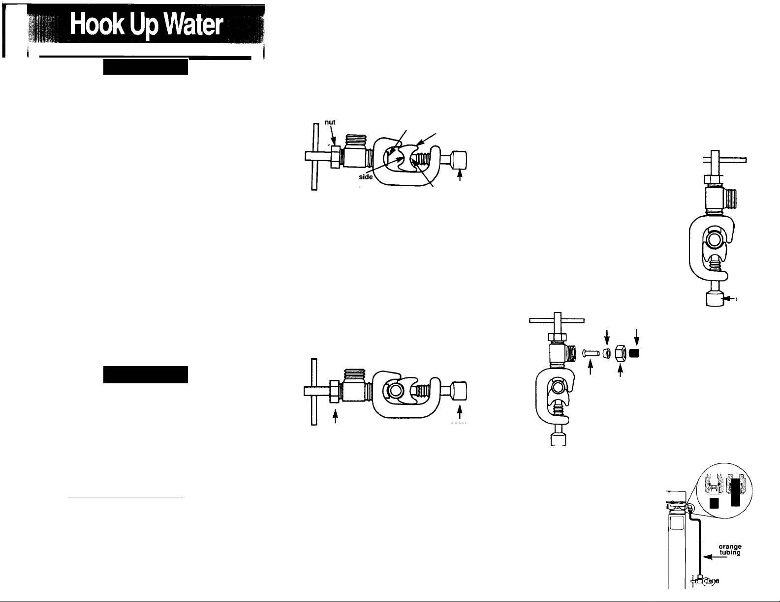
^ Connect saddle valve to cold water supply
I ■ soft copper pipe. Check that saddle valve
piercing lance does not protrude beyond rubber gas
ket. If it is protruding, carefully push it in flush with the
rubber gasket, using a hard object like the end of a
screwdriver handle. «¡ercing lance
small "U”
against soft
copper pipe
■ for 3/s" o.b.
pipe installation
shoula not
protrude. reversible
pipe installation
bracket
, screw
large "U” side
against soft
copper pipe for
yi6‘'^lo %''^O.D.
Assemble saddle valve on copper pipe.
lU ■ Saddle valve must be on top side of horizontal
pipe or side of vertical pipe to keep sediment from
collecting in its valve.
If you are connecting the saddle valve to %" O.D.
copper pipe, assemble bracket with small “U” side
against copper pipe to prevent distortion of pipe. If
you are connecting the saddle valve to to %"
O.D. pipe, assemble bracket with large “U” side
against copper pipe.
Tighten bottom screw firmly. DO NOT
1e.
overtighten; copper pipe could be crushed.
nut
Have a towel ready in case of leakage. Turn
III saddle valve handle clockwise until the lance
pierces soft copper pipe and then stops. Do not
continue to turn the saddle valve handle after it
has stopped because you may pierce through the
opposite side of pipe. The saddle valve is now in
the closed position.
^ Tu rn on cold water supply to check for
IQ ■ leaks. In case of leaks, use an adjustable
wrench to tighten nut below valve’s handle. Turn
cold water back off and proceed to step 1 k.
1 ll Connect saddle valve to cold water supply
Ilia rigid metai or piastic pipe. Use a grounded
electric drill or a hand drill to drill Vie" hole in top side
of horizontal pipe or side of vertical pipe. This will keep
sediment from collecting in valve. Turn saddle valve
handle clockwise to expose piercing lance a maximum
of 3/i6" beyond the rubber gasket. Align piercing lance
over hole you drilled in pipe. Then assemble saddle
valve on pipe with large “U" side against pipe.
Tighten bottom screw firmly.
1i
keeping bracket parallel to pipe.
Turn saddle valve handle clockwise until
]^-nut
piercing lance enters hole in pipe and then
stops. The saddle valve Is now in the
closed position.
4 : Have a towel ready in case of
IJ ■ leaks. Turn on cold water supply
to check for leaks. In case of leaks,
use an adjustable wrench to tighten
nut below valve’s handle. Turn cold
water back off.
41^ Remove cover from filtration
I IVb assembly by lifting straight up.
Move filtration assembly near
orange area where it will
sleeve tubing
*be mounted - either
under sink or in the
basement. For best
results, locate filtra
tion assembly so
insert
brass
compression
nut
tubing can be cut to
shortest length possi
ble. To connect one
' end of orange tubing to the saddle valve,
I place the brass compression nut on the
orange tubing (threaded side out) place the
plastic sleeve onto the tubing (discard
brass sleeve), push the insert into the
tubing and thread this assembly onto the opening of
the saddle valve. Tighten brass
compression nut with W wrench
Use a plastic tubing cutter or
sharp razor knife to cut tubing
to shortest possible length.
Make sure cut end is clean and
blunt and tubing is round. Push
free end of orange tubing as far
as it will go into the grey push-in
fitting on the front right side of
the filtration assembly.
Page 6
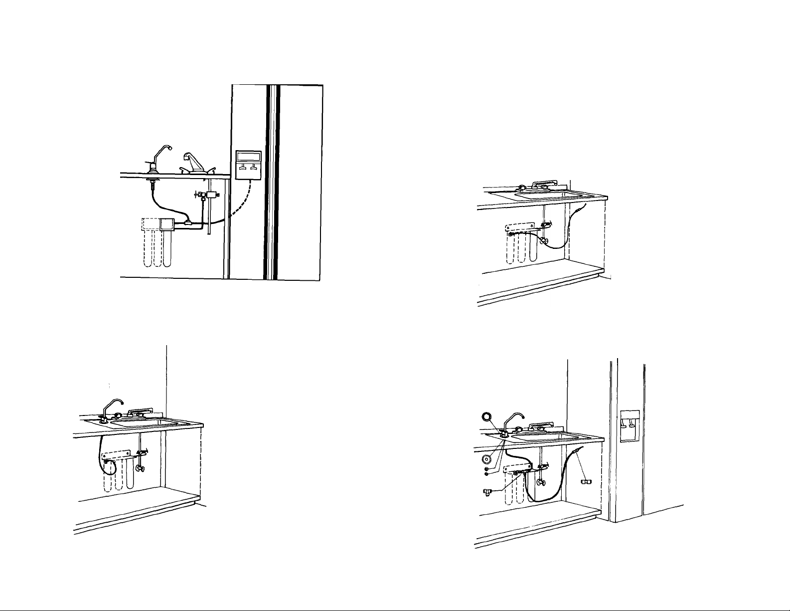
Instructions At A GlancG • For dotailGd instructions sgg following page.
1. Decide if the system will be connected to your
refrigerator, to an optional faucet or to both.
(Step 2a)
2. Connect refrigerator’s water supply to filtration
assembly with blue tubing. (Steps 2b-2c)
3. Or, install faucet in sink and connect blue tubing
to filtration assembly. (Steps 2d-2g)
4. Or, use “T” grey connector to connect both
refrigerator and faucet. (Steps 2h-2i)
Page 7
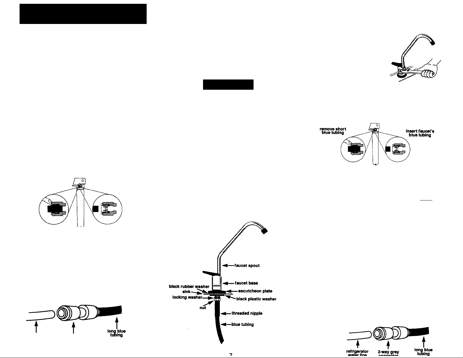
Syste m Conn ect ion
Oa You have three ¡nstallation options;
fcClB 1.Connect water supply from filtration system
2. Connect water supply from filtration system to
optional sink faucet only.
3. Connect water supply from filtration system to
both refrigerator and optional sink faucet.
All parts are included with this kit to connect refrigera
tor. If you choose to connect filtration system to a sink
faucet, order sink faucet, Part No. 4319154, available
from your Whirlpool dealer. This kit Includes: faucet
assembly with blue tubing attached, assembly hard
ware, faucet spout, 2-way grey connector with push-in
ends, and a ‘T” grey connector with push-in ends.
This “T" grey connector with push-in ends will allow
you to connect filtration assembly to both the faucet
and the refrigerator.
to refrigerator’s ice and water only.
Q Connect system to refrigerator only.
ing from grey connector with push-in end on the back
of filtration assembly. Insert one end of long piece of
blue tubing into this grey connector with push-in end.
Run the blue tubing from the filtration assembly to the
refrigerator.
fcWa blue tubing to shortest possible length. Insert
free end of blue tubing into the 2-way grey connector
with push-in ends as far as it will go. Turn off refriger
ator water supply and ice maker. Press refrigerator
water dispenser to empty water into a container.
Disconnect main water supply from refrigerator’s
water line. Seal main water line hole because it will
no longer be connected to refrigerator. Make sure the
refrigerator water line has a square cut. Then insert
refrigerator water line into other end of the 2-way grey
connector with push-in ends. Proceed to step 3.
Remove and discard short piece of blue tub
remove short
blue tubing
Route blue tubing to rear of refrigerator. Cut
Insert long
blue tubing
Connect system to optional sink faucet
VI a only. A 9/16" diameter opening in the sink is
required to install the optional sink faucet.
Important: If you do not have an existing sink
opening, contact a qualified installer or licensed
plumber to cut an opening in your sink.
! CAUTION
Property Damage
Contact a qualified instaiier or licensed
piumter for cutting a faucet opening in
your sink.
Faiiure to do so may result in damage to
the sink.
Remove and discard short clear piece of
■ tubing from top of faucet base and push
faucet spout into this opening. Place the escutcheon
plate and black rubber washer on the faucet’s thread
ed nipple. Note: Rubber washer may be removed
and replaced with a bead of plumber’s putty for a
neater appearance. Feed blue tubing through sink
hole. Position faucet spout over sink. Working below
the sink, secure faucet with black plastic washer,
locking washer and nut.
Side view of faucet
Recheck faucet position. If
2f.
position needs minor adjusting,
wrap the flat chrome sides of faucet
and the crescent portion of the
crescent wrench with masking
tape to protect the chrome from
scratches. Use the wrench on
flat sides of faucet to reposition
faucet. Remove masking tape.
Remove and discard short piece of blue
tubing from grey connector with push-in
encTon the back of filtration assembly. Cut blue tubing
from faucet to shortest possible length. Insert free
end of faucet’s blue tubing into this grey connector
Q ^ Connect system to refrigerator and
11 ■ optionai sink faucet. Follow steps 2d
through 2f for faucet installation. It is strongly recom
mended that only a licensed plumber or
professional installer cut an opening in i^
the sink. Cut blue tubing from faucet to * ^ '^J
shortest possible length. Push the —
faucet’s blue tubing as far as it will go .
onto one end of the‘T" grey connec- '
tor. Push the other end of the “T” grey refrigerator
connector as far as it will go onto the
short piece of blue tubing on the back
of the filtration assembly. Push the long
piece of blue tubing onto the center
push-in end of the “T" grey connector.
ty : Route blue tubing to refrigerator. Cut blue tub-
fcl a ing to shortest possible length. Insert free end
of blue tubing into the 2-way grey connector with push
in ends as far as it will go. Turn off refrigerator water
supply and ice maker. Press refrigerator water dis
penser to empty water into a container. Disconnect
main water supply from refrigerator’s water line. Seal
main water line hole because it will no longer be con
nected to refrigerator. Make sure the refrigerator water
line has a square cut. Then insert refrigerator water
line into other end of the 2-way grey connector with
push-in ends. Proceed to step 3.
refrigerator
water line
2-way grey
connector
Page 8
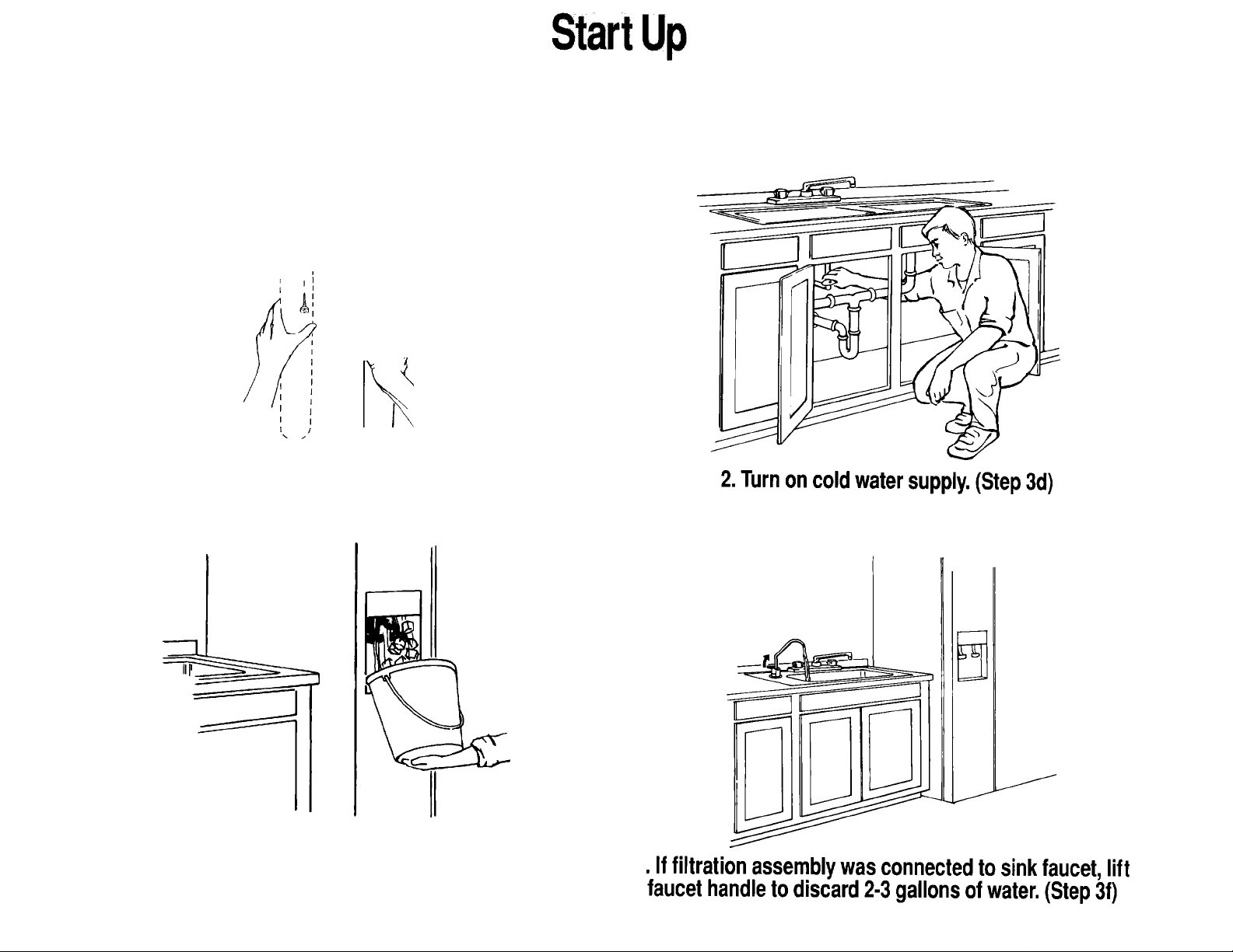
Instructions At A Glance • For detailed instructions see following page.
_L
Kj-i.
' I
h
1. Slide filtration assembly onto mounting screws.
(Steps 3a-3c)
3. If filtration assembly was connected to refrigerator,
make and discard 2 batches of ice and drain
2-3 gallons of water from water dispenser. (Step 3e)
Page 9

! WARNING
Electrical Shock Hazard
Special care must be taken when drilling into
walls. Electrical wires may be concealed behind
the wall covering:
• Use only an electric drill with a 3-wire power
supply cord connected to a grounded
receptacle.
• Check with qualified electrician if you are in
doubt as to whether your electric drill is
properly grounded.
Failure to follow these instructions could result
in personal Injury or death.
Mount filtration assembly:
Oua Solid Construction Cabinet: Position the
filtration assembly on either the right or left cabinet
wall and allow a minimum of 2” clearance above
the cabinet floor. Mark the location of the filtration
system's bracket holes, then set the filtration assem
bly aside and skip ahead to step 3b.
Non-solid Construction Cabinet: Replace filtration
assembly’s cover. Position the filtration assembly on
the cabinet floor along either the right or left cabinet
wall. Skip ahead to step 3c.
Basement Installation: Position the filtration
assembly on wood floor supports or on basement
wall. Mark the location of the filtration assembly’s
bracket holes, then set the filtration assembly aside.
Additional tubing may be required and is available
from your local plumbing distributor or from your
Whirlpool dealer. Continue with step 3b.
Place a towel or bucket under saddle valve,
OvI ■ then turn on cold water supply and saddle
valve and check for leaks.
If filtration assembly was connected to refrig
O" ■ erator, let ice maker produce two batches of
ice and discard both batches. This will flush the line
of any accumulated particles. If the refrigerator has a
water dispenser, flush the line by dispensing 2-3
gallons of water.
OX If optional sink faucet was installed, lift faucet
Ola handle and dispense and discard the first
2-3 gallons of water. To get filtered water hold the
faucet handle down for momentary flow, or hold the
faucet up for continuous flow. To stop water flow
from the faucet, return the faucet to the center or
horizontal position.
Gene ral Inf orm ati on
Due to shipping, some carbon grains may appear in the first few gallons of water through your filtration
system. Simply flush the system until water becomes clear.
This system can be connected to two dispensing points (including the optional sink faucet). We do not
recommend installing this water filtration system to your existing tap faucet as the flow rate will be
reduced to .6 gallons per minute.
Remember to cut all tubing to the shortest possible length to maximize your flow rate.
Maintenance of this water fiitration system is very important.
Replace the Sediment (S), Lead Reduction (L), and Carbon Filter (CF) cartridges annually. Failure to
maintain this water filtration system over an extended period of time could present health risks.
Q Drill pilot holes for the mounting bracket at
ODa the locations you’ve marked. Insert mounting
bracket screws in holes and tighten, leaving a slight
gap between screw head and wall.
For basement installation and solid construction
cabinet installation, place filtration assembly mount
ing bracket on mounting screws and tighten screws
until filtration assembly is secure and replace cover.
Make sure all tubing connected to grey
Owb push-in connectors is tight (pushed in as
far as it will go) and that tubing does not bind or kink
anywhere. Also make sure tubing does not interfere
with cabinet storage areas. Tubing may be cut to a
shorter length if necessary. Tubing may be secured to
cabinet walls with insulated staples as long as staples
do not crush or puncture tubing.
Page 10
Use & Care Information
Water Requirements
The filtration system must be connected to a cold
water supply line providing 30-100 psi water pressure.
The water temperature must be between 40°-100°F.
Community or private well water must be potable
(suitable for drinking).
! WARNING
Personal Injury Hazard
DO NOT use water filtration system if water is
microbioiogicaiiy unsafe or water quaiity is
unknown. Faiiure to follow these instructions
could result in personal injury.
General tips
• To correct a leaky saddle
valve, turn off cold water
supply and make sure bot
tom screw Is tightened evenly
I
nut
and firmly. DO NOT overtighten, you could crush
the pipe. Then make sure the nut below the
saddle valve's handle is tight. If not, tighten it
with a %" wrench.
• If the threaded portion of the brass compression nut
that is attached to the saddle valve leaks, turn off
saddle valve and remove the nut, wrap Teflon tape
around the threaded portion 2-4 times. Reconnect
the nut.
• If a leak should occur at a push-in connector, the
cause is usually defective tubing. To correct the
problem, turn off water supply to the
system either at the saddle valve or
other existing water valve. Push in the
grey push-in connector and hold; then
. pull the tubing out of the connector. Cut
“ \ at least V4" from the end of the tubing
clean, square cut using a plastic tubing Cutter or a sharp
razor knife. Make sure the cut end is clean and blunt
and that tubing is round. Reinsert tubing as far as it
will go. Turn on water supply at valve.
• If the refrigerator tubing leaks at the push-in connec
tor, the refrigerator's water line metal tubing may be
grooved or deformed. To correct the problem, turn
off water supply to the system either at the saddle
valve or other existing water valve. Press refrigerator
water supply or optional sink faucet to drain water
from system. Wait five minutes for filtration assembly
to depressurize. Push in the grey push-in connector
and hold; then pull the tubing out of the connector.
Cut at least 'A" from the end of the tubing to create a
new smooth end or replace if necessary.
30
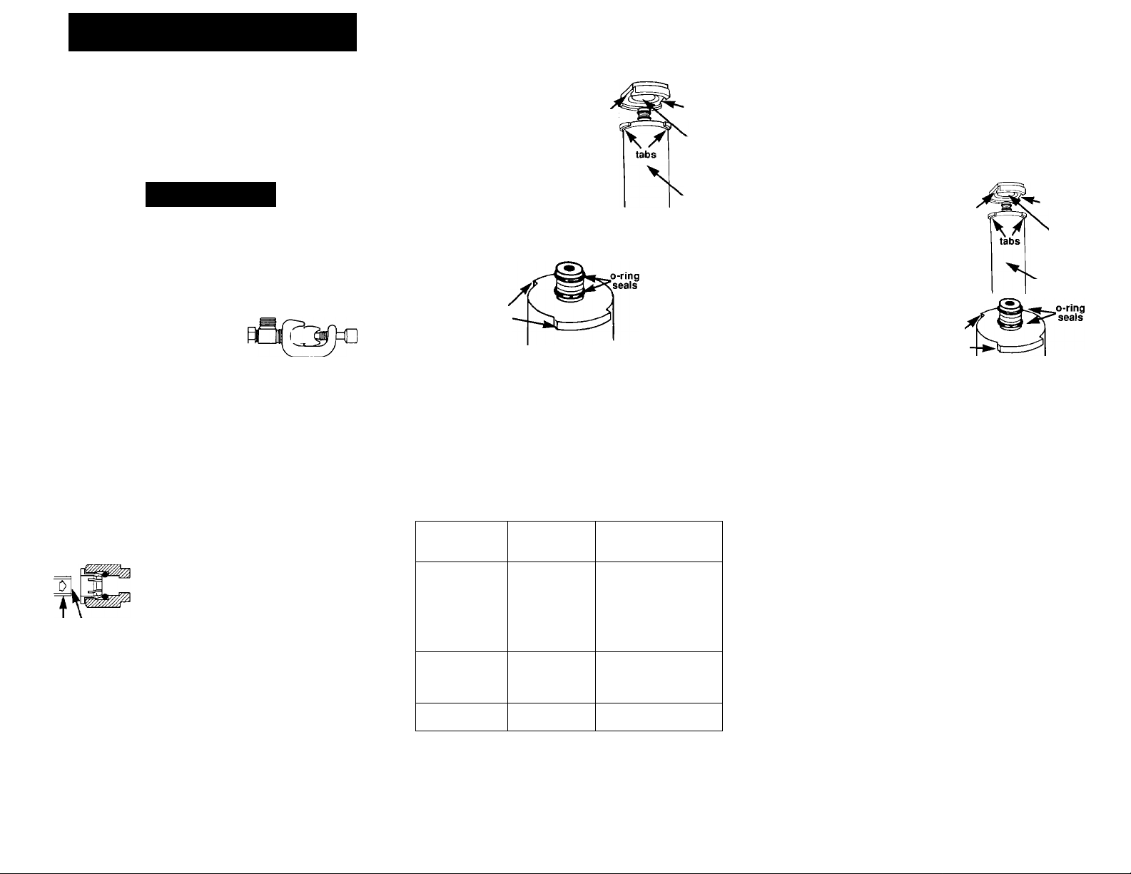
' If a cartridge head leaks, it may
have a misaligned, pinched or
damaged 0-ring. Shut off the slot
saddle valve or other existing
water valve. Press refrigerator
water supply or optional sink
faucet to drain water from system
Wait five minutes for filtration
assembly to depressurize. Turn
filter cartridge V4 turn to the left
and remove. Replace the 0-ring if
it is misaligned, pinched or damaged.
slot
receptacle
cartridge
Replacing filter cartridges
1. Turn off water supply at either saddle valve or
main shut-off. Press refrigerator water dispenser to
empty water into a container. If using the optional sink
faucet, turn on faucet to drain any water in system.
Discard this water. Wait five minutes for filtration
assembly to depressurize.
2. Lift cover off filtration assem
bly. Rotate cartridge one-quarter
turn to the left to remove connector
tabs from receptacle. Gently pull
slot
receptacle
down to remove cartridge.
tabs
3. Check that label on new cartridge
matches label above cartridge recep
tacle. Remove red cap from
cartridge. Wet 0-ring seals
cartridge
of new cartridge with a little
water. Line up the tabs at the ^
t
Maintaining your water
fiitration system
The maximum length of time a filter cartridge should
be used is one year. Cartridges should be replaced
every 500 gallons, but exactly how often cartridges
are replaced will depend on local water conditions.
Private wells may require more frequent cartridge
replacement while softened water systems may
require cartridge replacement only once a year.
top of the new cartridge with the slots in the filtration
assembly's receptacle. Push cartridge up and turn it
'A
turn to the right to lock it into place. Cartridge label
must face front. Pull down on cartridge to make sure it's
firmly in place. Repeat step if cartridge disconnects.
4. Turn water supply back on and check for leaks.
Open faucet and allow water to run for 5 minutes to
check system for leaks. If water is leaking, shut off
water and recheck connections. Replace cover.
Preparation for long periods of non-use
Follow these instructions if system will not be used for
Cartridge Replace at least
Sediment (SC)
Lead Reductien (L) Once/year or
Carbon (CF) Once/year or
Maintenance of this water filtration system is very important.
Replace the Sediment (S), Lead Reduction (L), and Carbon Filter
(CF) cartridges annuaiiy. Faiiure to maintain this water filtration
system over an extended period of fime could present health
risks.
Once/year or
every 1,000 gals.
every 500 gals.
every 500 gals.
Or replace if or when...
•Water supply is cloudy,
has high dirt and rust
content (change every
six months)
• Water amount or flow
from faucef is noticeably
reduced
•Water supply smells
of chlorine
•Wafer supply smells
of chlorine or water
has high dirt and rust
content (change every
six months)
•Water has “off" fasfe
or odor
more than 30 days.
1. Turn off water supply at either saddle valve or
main shut-off. Press refrigerator water dispenser to
empty water into a container. If using the optional sink
faucet, turn on faucet to drain any water in system.
Discard this water. Wait five minutes for filtration
assembly to depressurize.
2. Remove all cartridges and place upside down in
sink or bucket to drain water from cartridges. Place
cartridges in plastic bag and seal tightly. Place bag
with cartridges in refrigerator. Do Not allow cartridges
to freeze.
Using water filtration system after long
periods of non-use
1. Follow instructions for replacing cartridges.
2. Follow "Start Up” instructions (3e and 3f).
10
Page 11
Call 1-800-253-1301 to order.
Replacement Parts & Accessories
System I Replacement Cartridge Kit
Kit includes Sediment/Carbon (SC) Cartridge
System II Replacement Cartridges Kit
Kit includes Lead Reduction (L) and Carbon
Filter (CF) Cartridges. Cartridges can also be
ordert individually.
System III Replacement Cartridge Kit
Kit includes Lead Reduction (L) and two
Carbon Filter (CF) Cartridges. Cartridges can
also be ordert individuallv.
Sediment/Carbon (SC) Cartridge 4373529
Lead Reduction (L) Cartridge ’
Carbon RIter (CR Cartridge
Connector with Push-in Ends 4319153
Faucet Assembly
System III Filtration Assembly Cover
System II Filtration Assembly Cover
System I Filtration Assembly Cover 4373565
Saddle Valve
Additional Parts
Needed for Multiple
Connections:
Additional tubing for basement installation
T’ Connector with Push-in Ends 4319152
4373529
4373573
4373574
4373530
4373531
4319154
4373563
4373564
4373572
Tubing 4319151
4319151
If You Need Assistance...
The Whirlpool Consumer Assistance Center will answer
any questions about operating or maintaining your
water filtration system not covered in the Installation
Instructions and Use and Care Guide. The Whirlpool
Consumer Assistance Center is open 24 hours a day,
7 days a week. Just dial 1-800-253-1301 - the call is
free. When you call, you will need the water filtration
system model number and serial number. Both num
bers can be found labeled on the filtration assembly.
WATER FILTRATION SYSTEM I
MODEL NO. WSC100YW
Whirlpool
NOTICE; ACTIVATED CARBON FILTERS ARE NOT INTENDED FOR USE WITH WATER THAT IS MICROBIOLOGICALLY
UNSAFE OR WITH WATER OF UNKNOWN QUALITY WITHOUT ADEQUATE DISINFECTION BEFORE OR AFTER THE UNIT.
PLEASE READ THE PERFORMANCE DATA SHEET.
THIS PRODUCT HAS BEEN TESTED AND LISTED UNDER NSF STANDARD 42 FOR CHLORINE, TASTE AND ODOR
REDUCTION (CLASS I) AND PARTICULATE REDUCTION (CLASS II).
WHIRLPOOL, BENTON HARBOR, Ml, USA. / MO C
IT IS ESSENTIAL THAT OPERATIONAL, MAINTENANCE AND FILTER REPLACEMENT REQUIREMENTS ( Nbrci
BE CARRIED OUT FOR THE PRODUCT TO PERFORM AS ADVERTISED.
Whirlpool
NOTICE; ACTIVATED CARBON FILTERS ARE NOT INTENDED FOR USE WITH WATER THAT IS MICROBIOLOGICALLY
UNSAFE OR WITH WATER OF UNKNOWN QUALITY WITHOUT ADEQUATE DISINFECTION BEFORE OR AFTER THE UNIT.
PLEASE READ THE PERFORMANCE DATA SHEET.
THIS PRODUCT HAS BEEN TESTED AND LISTED UNDER NSF STANDARD 42 FOR CHLORINE, TASTE AND ODOR
REDUCTION (CLASS I) AND PARTICULATE REDUCTION (CLASS II) AND UNDER NSF STANDARD 53 FOR LEAD,
CYST AND TURBIDITY REDUCTION.
WHIRLPOOL, BENTON HARBOR, Ml, USA.
IT IS ESSENTIAL THAT OPERATIONAL, MAINTENANCE AND FILTER REPLACEMENT REQUIREMENTS
BE CARRIED OUT FOR THE PRODUCT TO PERFORM AS ADVERTISED.
REPLACEMENT CARTRIDGE: WHIRLPOOL SC FSP# 4373529
RATED SERVICE FLOW - 0.6 gpm (2.28 Ipm)
MAX. OPERATING PRESSURE -100 psig (862 kPa)
MAX. OPERATING TEMPERATURE 100°F (38°C)
WATER FILTRATION SYSTEM II
MODEL NO. WSC200YW
REPLACEMENT CARTRIDGE: WHIRLPOOL L FSP# 4373530 WHIRLPOOL CF FSP# 4373531
RATED SERVICE FLOW - 0.6 gpm (2.28 Ipm)
MAX. OPERATING PRESSURE -100 psig (862 kPa)
MAX. OPERATING TEMPERATURE 100°F (38°C)
How To Arrange For Service...
In the event that your Whirlpool appliance should ever
need service, call the dealer from whom you purchased
the appliance or a Whirlpool-authorized service
company. A Whirlpool-authorized service company is
listed in the Yellow Pages of your telephone directory
under "Appiiances-Major-Service or Repair.” You can
also obtain the service company’s name and telephone
number by dialing, free within the continental United
States, the Whirlpool Consumer Assistance Center
telephone number, 1-600-253-1301. A special operator
will tell you the name and number of your nearest
Whirlpool-authorized service company.
Maintain the quality built into your Whirlpool appliance call a Whirlpool-authorized service company.
WATER FILTRATION SYSTEM III
MODEL NO. WSC300YW
Whifipoal
NOTICE: ACTIVATED CARBON FILTERS ARE NOT INTENDED FOR USE WITH WATER THAT IS MICROBIOLOGICALLY
UNSAFE OR WITH WATER OF UNKNOWN QUALITY WITHOUT ADEQUATE DISINFECTION BEFORE OR AFTER THE UNIT.
PLEASE READ THE PERFORMANCE DATA SHEET.
THIS PRODUCT HAS BEEN TESTED AND LISTED UNDER NSF STANDARD 42 FOR CHLORINE, TASTE AND ODOR
REDUCTION (CLASS I) AND PARTICULATE REDUCTION (CLASS II) AND UNDER NSF STANDARD 53 FOR LEAD,
CYST AND TURBIDITY REDUCTION. SEE PERFORMANCE DATA SHEET FOR PERMISSIBLE VOC CLAIMS.
WHIRLPOOL, BENTON HARBOR, Ml, USA.
IT IS ESSENTIAL THAT OPERATIONAL, MAINTENANCE AND FILTER REPLACEMENT REQUIREMENTS
BE CARRIED OUT FOR THE PRODUCT TO PERFORM AS ADVERTISED.
REPLACEMENT CARTRIDGE: WHIRLPOOL L FSP# 4373530 WHIRLPOOL CF FSP# 4373531
RATED SERVICE FLOW - 0.6 gpm (2.28 Ipm)
MAX. OPERATING PRESSURE -100 psig (862 kPa)
MAX. OPERATING TEMPERATURE 100°F (38°C)
11
Page 12
Perf orma nce Da ta She et
This product has been tested and listed by NSF International under
Standard 42 for Taste, Odor and Chlorine reduction (Class I) and
Particulate reduction (Class II).
Whirlpool Water Filtration System I
Model No. WSC100YW
SPECIFICATIONS: Taste/Odor/Chlorine reduction (Class I) CAPACITY: 1,000 Gallons
General
Performance
Chlorine'
Particulate 560,000 part/mL^
Performance may very based on local water conditions.
^Free Available Chlorine.
n'est requirement is at least 10,000 particles/mL of AC Fine Test Dust.
SERVICE FLOW RATE: 0.6 GPM (2.2 Umin) @ 60 psi
Average
Influent
2.0 mg/L <0.1 mg/L 92%
Maximum
Effluent
18,000 part/mL 98%
Minimum%
Reduction
reduction (Class 1)
reduction (Class II)
NSF Test
Requirement
minimum 75%
minimum 85%
This product has been tested and listed by NSF International under Standard 42
®) for Taste, Odor and Chlorine reduction (Class I) and Particulate reduction (Class
II) and under Standard 53 for Cyst, Turbidity and Lead reduction.
Whirlpool Water Filtration System II
Model No. WSC200YW
SPECIFICATIONS: Lead and Taste/Odor/Chlorine reduction (Class I) CAPACITY: 500 Gallons
General
Performance
Chlorine’ 2.0 mg/L <0.1 mg/L 92%
Particulate
Cyst 215,000 4-6 n/mL3
Turbidity
Contaminant
Reduction
Performance^
Lead @ pH 6.5 0.015 mg/L 0.16 mg/L^
Lead @ pH 8.5 0.015 mg/L 0.17 mg/mL®0.002 mg/L
^Free Available Chlorine.
H'est requirement is at least 10,000 partides/mL of AC Fine Test Dust.
^est requirement is 4-6 micrometer size partides per mL of influent.
^These contaminants are not necessarily in your water supply. Performance may vary based on local water conditions.
®Test requirement 0.15 mg/L± 15%.
SERVICE FLOW RATE: 0.6 GPM (2.2 Umin) @ 60 psI
Average
Influent
560,000 part/mL^ 18,000 part/mL
14NTU
U.S. EPA
MCL
Maximum
390 4-6 p/mL
Average
influent
Effiuent
0.42 NTU
Maximum
Effluent
0.005 mg/L 97%
Minimum%
Reduction
98%
99.9%
97%
Minimum%
Reduction
99%
reduction (Class 1)
minimum 85%
reduction (Class II)
minimum 99.9%
minimum effluent
maximum effluent
maximum effluent
NSF Test
Requirement
minimum75%
reduction
1.0 NTU
NSF Test
Requirement
0.015 mg/L
0.015 mg/L
12
Page 13
Perf orma nce Da ta She et
This product has been tested and listed by NSF International under Standard 42
® ] for Taste, Odor and Chlorine reduction (Class I) and Particulate reduction (Class
II) and under Standard 53 for Cyst, Turbidity, Lead and VOC reduction.
Whirlpool Water Filtration System
SPECIFICATIONS: Lead, VOC and Taste/Odor/Chlorine reduction (Class I) CAPACITY: 500 Gallons
General
Performance
Chlorine'
Particulate 560,000 part/mL^
Cyst
Turbidity
SERVICE FLOW RATE: 0.6 GPM (2.2 Umin) @ 60 psi ^
Average
Maximum
Influent
2.0 mg/L <0.1 mg/L
18,000 part/mL 98%
215,000 4-6n/mL3
14NTU 0.42 NTU
390 4-6 ti/mL
Effluent
Mlnlmum%
Reduction
92%
99.9%
97%
NSF Test
Requirement
minimum75%
reduction (Clas^ 1)
minimlim 85%
reduction (Class II)
minimum 99.9%
minimum effluent
reduction
1.0 NTU
Systems I, II &
APPLICATION GUIDELINES/WATER SUPPLY PARAMETERS
Water supply - community or private well
Water Pressure
Water Temperature
pH Range
Maximum TDS Level
Dissolved Iron
Dissolved Manganese
Turbidity
Water supplies that exceed limits for iron or manganese require (xetreatment.
It is essential that operational, maintenance and filter replacement requirements be carried out for the product to perform
as adv^ised.
CAUTION: Do Not use where water is microbiologically unsafe or wKh water of unknown quality without adequate
disinfection before or after the unit.
Potable (suitable for drinking)
30-100 psi (207 - 690kPa)
40° - 100°F (4.4° - 38°C)
6-9
500 ppm
< 0.1 ppm
< 0.05 ppm
< 1 NTU
Contaminant
Reduction
Performance"
Lead @ pH 6.5
Lead @ pH 6.5
'Free Available Chlorine.
^est requirement is at least 10,000 Partides/mL of AC Fine Test Dust.
^esl requirement is 4-6 micrometer size particles per mL of influent.
^These contaminants are not necessarily in your water supply. Performance may vary based on local water conditions.
^Tes1 requirement 0.15 mg/L± 15%.
U.S. EPA
MCL
0.015 mg/L
0.015 mg/L 0.17 mg/L® 0.002 mg/L 99%
Average
infiuent
0.16 mg/L5
Maximum
Effluent
0.005 mg/L
Minimum%
Reduction
97%
NSF Test
Requirement
maximum effluent
0.015 mg/L
maximum effluent
0.015 mg/L
VOLATILE ORGANIC CHEMICAL REDUCTION
This system has met the testing requirements of Standard 53, Section 5.1.1 for the
reduction of chloroform, which is the surrogate for the foliowing chemicals
Chemical Levels (ppb) Level (ppb)
Benzene 30'
Carbon Tetrachloride 40'
p-Dichlorobenzene 80®
Trichloroethylene 300'
Trihalomethanes 300 15
(surrogate chemical)
1,1 -Dichloroethylene 50'
1,1,1 -T richloroethane 80®
1,2-Dichloroethane 100'
Ethylbenzene 80®
Tetrachloroethylene 80®
Toluene 80®
1,2-Dichloropropane 80® 5®
'Influent levels are the 95th percentile, cxxurrence levels are per Federal Register, Vol. 50, No. 219, November 13,1965, p
^Since the 95th percentile occurrence levels were too low and thus were not pertinent for testing these chemicals against their MCL’s,
a reasonable level was selected for surrogate testing as shown.
^EPA Primary Maximum Contaminant Levels
^Maximum effluent concentrations set at the practical quantitation level (POL) which is less than the MCL.
^In the absence of officially stated occurrence levels and MCL’s, the surrogate influents were selected to provide a reasonable test.
Occurrence Effluent
Maximum Influent
Other VOC’s’
5®
5® Chlorobenzene
5"
5® ortho-Xylene
7® 1,2-Dichlorobenzene 80
5" 1,2-Dichloroethane
5®
4"
4"
4"
cis-1,3-Dichloropropene 80 95%
Hexachlorobutadiene 40
trans-1,2-Dichloroethene 80
1,1,2,2-Tetrachloroethane80 95%
Concentration
(ppb)
80 95%
80 95%
80 95%
Minimum
Percent
Reduction
95%
95%
95%
46917.
WARRANTY
Length of Warranty:
One Year Full Warranty
(From date of purchase)
Five Year Limited Warranty
(Second through fifth year
from date of purchase)
Whirlpool will not pay for:
A. Service calls to:
1. ) Correct the installation of the product. System must be installed and operated in accor
dance with Whirlpool procedures and guidelines.
2. ) Instruct you how to use the product.
3. ) Correct house plumbing.
B. Repairs when product is used in other than normal, single-family household use.
C. Repairs when product Is damaged from neglect, misuse, abuse, freezing or hot water, fouling
with sediment or scale, bacterial attack, alterations, improper installation, or installation not in
accordance with local plumbing codes.
D. Any labor costs during the limited warranty.
E. Replacement parts or repair labor costs for units operated outside the U.S.
F. Pickup and delivery. This product is designed to be repaired in the home.
G. Repairs to parts or systems caused by unauthorized modifications made to the product.
The performance and functioning of your water filtration system is directly related to the quality of
the water being treated and the particular application in which it Is used. Please consult "Water
Requirements” and “Use & Care”.
Whiripool shall not be liable for Incidental or consequential damages. Some states do not allow
the exclusion or limitation of incidental or consequential damages, so this limitation or exclusion may
not apply to you.
This warranty gives you specific legal rights, and you may also have other rights which vary from
state to state.
13
Whirlpool will pay for:
Replacement parts and repair labor to correct defects
in materiais or workmanship for the entire product
except for the filter cartridge(s). Service must be
provided by an authorized Whirlpool servicing outlet.
Replacement parts to correct defects in materials or
workmanship for the entire product except for the
filter cartridge(s).
Page 14

'Whirlpool
CORPORAriON
Part No. 4373576
©1993 Whirlpool Corporation
Whirlpool Corporation
Benton Harbor, Ml 49022
Printed on Recycled Paper in U.S.A.
 Loading...