

Page 1
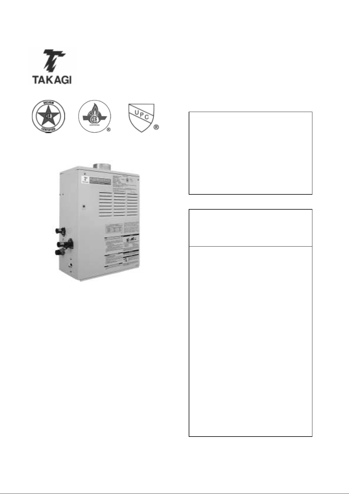
T-K2 Instantaneous Water Heater
Installation Manual and Owner’s Guide
Flash Water Heater
Model T-K2
Suitable for potable water heating and space heating
FEATURING
• ENDLESS HOT WAT ER
• ON DEMAND
• COMPACT, SPACE SAVING
• ENERGY CONSER VING
• COMPUTER CONTROLS
• COMPUTERIZED SAFETY
• NO PILOT LIGHT
Takagi Industrial Co. USA Inc.
6 Goddard
Irvine, CA 92618
Toll Free (888) 882-5244
www.takagi-usa.com
FOR YOUR SAFETY - This product
must be installed and serviced by a
professional service technician or
licensed person, qualified in water
heater installation. Operation creates
carbon monoxide gas and flue gases,
which can cause serious injury or
death. Improper installation and/or
operation, or installation by an
unqualified person, will void warranty.
WARNING: If the information in this
manual is not followed exactly, a fire or
explosion may result, causing property
damage, personal injury or death.
• Do not st o re or us e g asoli ne or other
flammable vapors or liquids in the
vicinity of this or any other
appliance.
• WHAT TO DO IF YOU SMELL GAS
• Do not use any appliance.
•
Do not touch any electrical
switch
in your building.
Immediately contact your gas
•
supplier from another
location. Follow the gas
supplier’s instruc tio n s.
If you cannot reach your gas
•
supplier, call the fire
department.
• Installation and service must be
performed by a qualified installer,
service agency or the gas supplier.
, do not use any phone
Page 2

Table of Conten t s
Specifications…………………………….. 2
For Your Safety…………………………... 3
Operation…………………………………. 4
General…………………………… 4
Turning It On……………………… 4
Turning It Off……………………… 4
Temperature……………………… 4
Flow……………………………….. 4
Freeze Protection………………... 5
Installation………………………………… 6
General…………………………… 6
Accessories………………………. 6
Electrical Connections…………... 6
Wiring Diagrams…………………..7,8
Gas Supply Piping………………. 9
Water Plumbing………………….. 10
Pressure Relief Valve……………. 10
Wall Hanging Installation………... 11
Standing Installation……………... 11
Outdoor Installation……………… 11
Indoor Installation………………... 12
Combustible Air Supply…. 12
Exhaust Venting…………. 13
Manufactured Home (Mobile Home)
Installation……………….………... 13
Indoor……………………… 13
Outdoor……………………. 13
Initiating the Appliance…………... 14
Initial Operation…………………... 14
Space Heating Application……….. 15
Applications………………………. 19
Storage Tank……………... 19
Recirculation……………… 19
Maintenance……………………………… 20
Troubleshooting………………………….. 20-22
Optional Items……………………………. 23
TK-RE01………………………….. 23
TK-BK01………………………….. 23
TK-TV01…………………………... 23
TK-TV03…………………………... 23
TK-TV04…………………………… 23
Dipswitch Settings………………………... 24
Indoor NG Dipswitch Settings…… 24
Outdoor NG Dipswitch Settings…. 24
Indoor LP Dipswitch Settings……. 25
Outdoor LP Dipswitch Settings….. 25
Exploded Diagrams………………………. 26-29
Parts List………………………………….. 30
Flow Chart……………………………….. 31
Specifications
Natural Gas Input Min. 20,000 Btu
Max. 185,000 Btu
LPG Input Min. 19,000 Btu
Max. 175,000 Btu
Gas Connection ¾” NPT
Water Connections ¾” NPT
Water Pressure Min. 15 psi
Max. 150 psi
Natural Gas Pressure Inlet Min. 5” WC
Max. 10.5” WC
LP Gas Pressure Inlet Min. 11” WC
Max. 14” WC
Manifold Pressure Natural 2.3” WC
Propane 2.5” WC
Weight 60 lbs.
Dimensions 24.5”x16.5”x8.3”
Ignition Electronic Ignition
Electrical Supply AC 120 V
***
• Inlet gas pressure must not exceed the
above maximum values.
• For gas pressures lower than 5” WC for
natural gas, call the manufacturer.
• Before installing in areas over 4,500 feet
above sea level, contact the manufacturer
for high altitude adjustment instructions.
• Check the rating plate to insure this
product matches your specifications.
• Takagi - USA is constantly improving our
products, therefore specifications are
subject to change without prior notice.
Page 3
For Your Safety
PLEASE READ THIS MANUAL CAREFULLY
AND FOLLOW IT EXACTLY FOR YOUR
SAFETY.
1. Follow all l ocal codes, or in t he abs enc e of
local codes, follow the most recent edition
of the National Fuel Gas Code, ANSI
Z223.1/NFPA 54 in USA or the CGA
standard, CAN/CGA B149.1 or .2
Installation Codes for Gas Burning
Appliances in Canada.
2. Properly ground the unit in accordance
with all local codes, or in the absence of
local codes, with the National Electrical
Codes, ANSI/NFP A 70 in the US A or CSA
standard C22.1 Canada Electrical Code
Part 1 in Canada.
3. Carefully plan where to install your Flash
Water Heater. Insure that your heater will
have enough combustible air, proper
ventilation, and locate your heater where
water leakage will not do damage to
surrounding areas. If there is a possibility
of water damage, install a suitable drain
pan under the unit, which will not restrict
combustible airflow.
4. Check the rating plate for the correct gas
type, gas pressure, water pressure, and
electrical rating. Do not install this unit if
these requirements can’t be met.
Device will only work if the unit has pro per
electrical power. The Freeze Prevention
Device is rated for temperatures down to
5º F (-15º C) in a wind free environment.
The wind chill factor will cause the Flash
Water Heater to freeze and be damaged at
temperatures above 5º F (-15º C). Refer to
the sections on Winterizing and the Freeze
Prevention Device for more information.
7. WARNING: Before bathing or showering
always check the water temperature. Do
not leave children or the infirm
unsupervised in the shower or bath. The
water temperat ure is set at 120º F ( 50º C)
from the factory to maximize the amount of
hot water you can use. Water temperature
over 125º F can cause severe burns
instantly or death from scalds.
8. WARNING: Do not use this appliance if
any part has been underwater.
Immediately call a certified and trained
technician to inspect and service the unit if
necessary.
9. WARNING: Do not store or use gasoli ne or
other flammable vapors or liquids in the
vicinity of this or any other appliance.
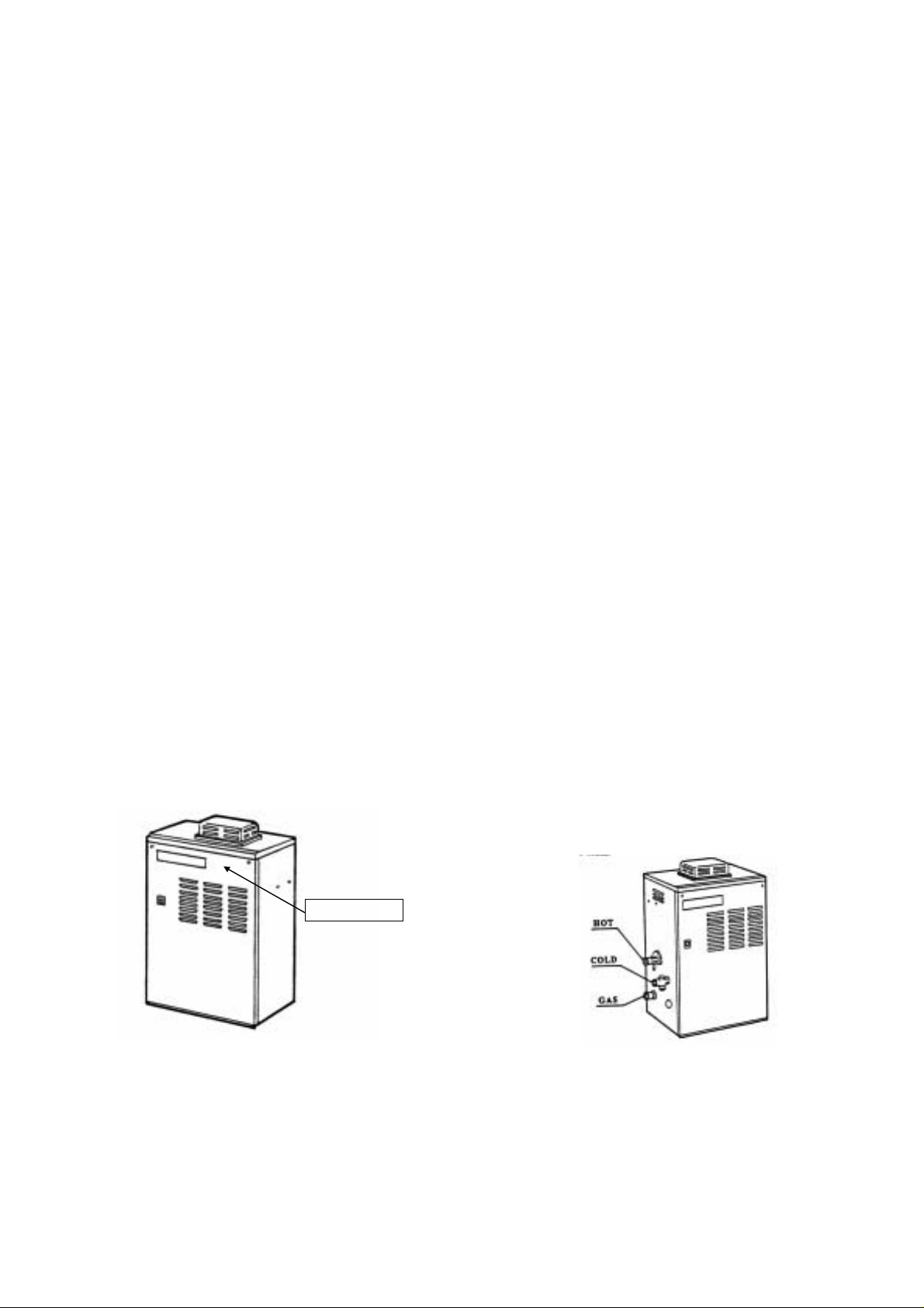
10. WARNING: Do not reverse the water and
gas connections, this will damage your
heater and can cause severe injury or
death from scalds. Follow the diagram
below when installing your Flash water
heater.
Rating plate
5. If a problem should occur, turn off all hot
water taps and turn off the gas. Call a
trained technician, the Gas Company, or
the manufacturer.
6. WARNING: Do not disconnect the
electrical supply if the temperatures will be
near freezing. The Freeze Prevention
Page 4
Operation
General
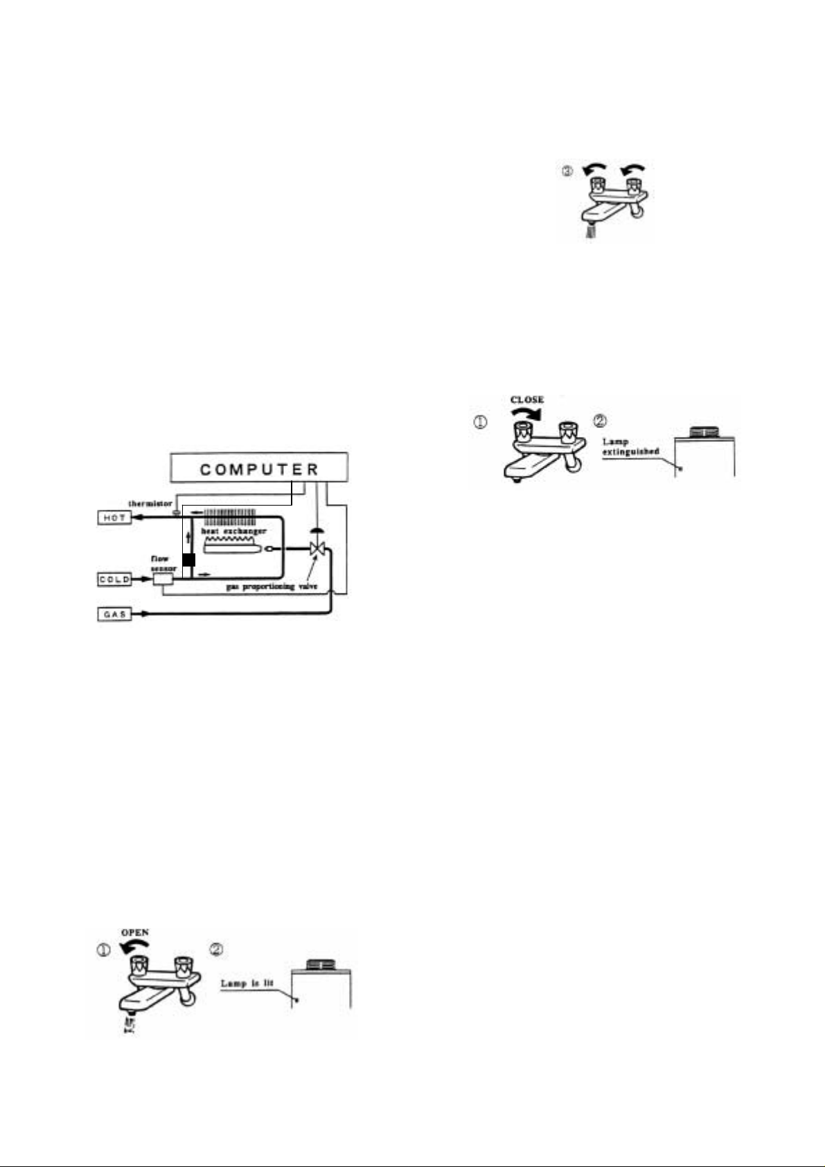
The Flash Water Heater is an instantaneous,
tankless water heater designed to efficiently
supply domestic or commercial hot water. The
principle behind the Flash water heater is
simple: Once a hot water tap is opened, the
Flash’s flow sensor detects that hot water is
needed, and automatically commands the
computer to electronically ignite the burners,
and heat water. During operation, the
computer monitors the water temperature and
flow rate, and controls the gas flow and fan
speed to maintain a constant output
temperature. After the burners are ignited the
“fire on” lamp will be lit.
0.75 gallons per minute is required to t urn the
burners on, but after the burners are ignited,
the flow rate can drop to 0.6 gallons per
minute without the burners turning off.
As long as water, gas and electricity are
connected, there will be an endless flow of hot
water. To turn on your water heater, just open
a tap. To turn the heater off, just close the tap.
Turning It On
To turn on the Flash water heater
1. Open a hot water tap, or turn on water
demanding appliance.
2. Unit will detect flow, burners will ignite,
“Fire On” lamp will light up.
3. If necessary, mix in cold water to get a
comfortable temperature.
Turning It Off
To turn off the Flash water heater
1. Close the hot water tap, or turn appliance
off.
2. Flow will diminish, unit will shut off.
3. “Fire On” lamp will go out.
Temperature
The output temperature of the T-K2 has been
factory set for a maximum 120° F (50° C).
This is electronically controlled by the
computer and can be adjusted with a TKRE01 temperature controller, or with the
dipswitches on the computer board (See pgs.
21-22 for dipswitch settings). Further
adjustment may be made by mixing in cold
water with the hot to obtain the ideal water
temperature.
The flow rate possible out of the unit is
dependent on the temperature setting chosen.
Consult the flow charts on the last page of this
unit to determine the possible outlet
temperature and flow rate combinations.
WARNING: Temperatures above 125º F (52º
C) can cause severe burns or death from
scalding. Children, the disabled and the
elderly are at a high risk of being injured. Feel
the water temperature before bathing or
showering. Do not leave children, disabled
persons, or the elderly unsupervised.
Flow
Page 5
The flow rate through the T-K2 is limited to a
maximum of 6.9 GPM. The temperature
setting, along with the supply temperature of
the water will determine the f low rate the unit
puts out. Consult the flow charts on the last
page of this manual to determine t he possible
outlet temperature and flow rate combinations.
Based on the United States Department of
Energy method of testing water heater output,
the T-K2 is rated for 240 gallons per ho ur, or
4.0 GPM, at a 77° F rise above the inlet
temperature. Refer to the following chart of
typical household flow rates to determi ne what
the T-K2 can do in a household application.
Remember that for bathing, cold water will be
mixed for a comfortable temperature,
increasing the flow output rate.
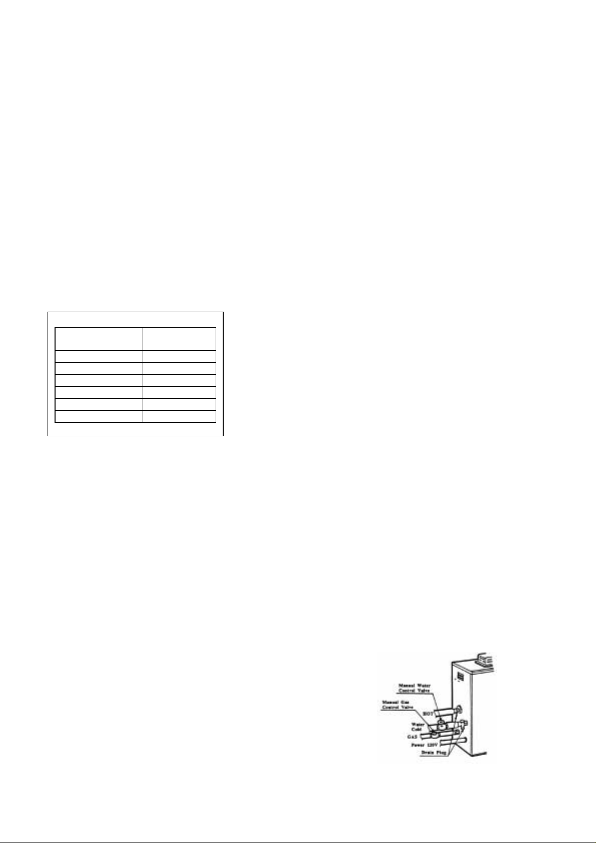
Household Fl ow Rates
Appliance / Use
Lavatory Faucet 1.0
Bath Tub 4.0
Shower 2.0
Kitchen Sink 1.5
Dishwasher 1.5
Washing Machine 2.0
Taken from UPC 1997
Freeze Prevention
Flow Rate
(GPM)
This unit comes equipped with heaters that
discourage the unit from freezing. For this
freeze prevention system to operate there has
to be electrical power to the unit.
The f reeze preven tion devi ces will not work if
the electrical power source is disconnected.
The unit has been rated for temperatures
down to 5º F (-15º C) in a wind free
environment. The wind chill factor will cause
the unit to freeze at temperatures above 5º F
(-15º C), even if the unit is installed indoors.
For indoor installation in areas where the
temperature will be well below freezing for
extended periods of time, use the thermostat
extension cable to extend the internal
thermostat to the outdoors, and install a TKTV03 backflow prevention kit so that cold air
will not backflow into the flue and cause the
unit to freeze. Do not install the water heater in
an area with extrem ely cold we ather. Thi s will
void your warranty and Takagi Industrial Co.
USA Inc. will not be responsible for any
damage that occurs.
WARNING: The pipe heaters are located on
the Flash Water Heater only. Any hot or cold
water pi pes loc ated ou tside of the uni t will not
be protected. Properly protect and insulate
these pi pe s from fr ee zing.
If the heater will not be in use for a long period
of time or if the temperatures will drop below
5º F (-15º C) with the wind chill factor, turn off
heater and drain the unit of water. This applies
to indoor and outdoor installations. This will
keep the unit from freezing and being
damaged.
Follow these instructions carefully:
1. Turn off the power supply to the Flash
Water Heater.
2. Close manual gas control valve.
3. Close manual water shut off valve.
4. Open all hot water taps in the house.
(Bathroom, kitchen, laundry room, etc.).
When the water flow has ceased, close all
hot water taps.
5. Have a bucket or pan ready to catch the
water f rom the unit’s drain plugs . Remove
the drai n pl ugs t o dra in the wa te r out of t he
unit.
6. Let drain for 5 minutes.
7. Securely screw the drain plugs back into
place.
Follow these steps when it is again safe to use
the water heater:
1. Make sure all hot water taps are closed
and the drain plugs are securely attached.
2. Purge the water line of debris.
3. Open manual water control valve located
on the water supply line.
4. Open all the hot w ater taps to verify water
flows to the taps. Close hot water taps.
5. Op en manual gas control valve located on
the gas supply line.
6. Turn on the power supply to the Flash
Water Heater.
Page 6
Installation
This section is for the installer. The
installer is responsible for the correct
installation of your Fla sh Wat er H ea ter.
For Your Safety: Only a certified and
trained service technician or qualified
plumber may service or install your
product.
Please ke ep this owner’s ma nual in a safe
place for future reference. Copies of this
manual are available from TAKAGI-USA
General
All gas water heaters require careful and
correct installation to ensure safe and efficient
operation. This manual must be followed
exactly.
1. Read the For Your Safety section in the
beginning of this manual.
2. This unit is not capable of being used as a
pool or spa heater.
3. The regulator is preset at the factory. It is
computer controlled and should not need
adjustment.
4. Suitable for potable water heating only.
Well wa ter or h ard water m ay cause s cale
problems that will not be covered by the
manufacturer’s warranty.
5. Maintain pr oper spac e for servi cing. Inst all
the unit so that it can be connected or
removed easily.
6. Install so that the electrical power can be
switched off if necessary.
7. Avoid installing in an area with high levels
of dust, sand or debris. Particles may clog
the air vent, reduce fan function, or cause
improper combustion.
8. Do not install the unit where the exhaust
vent is pointing into any opening in a
building or where the noise may disturb
your neighbors.
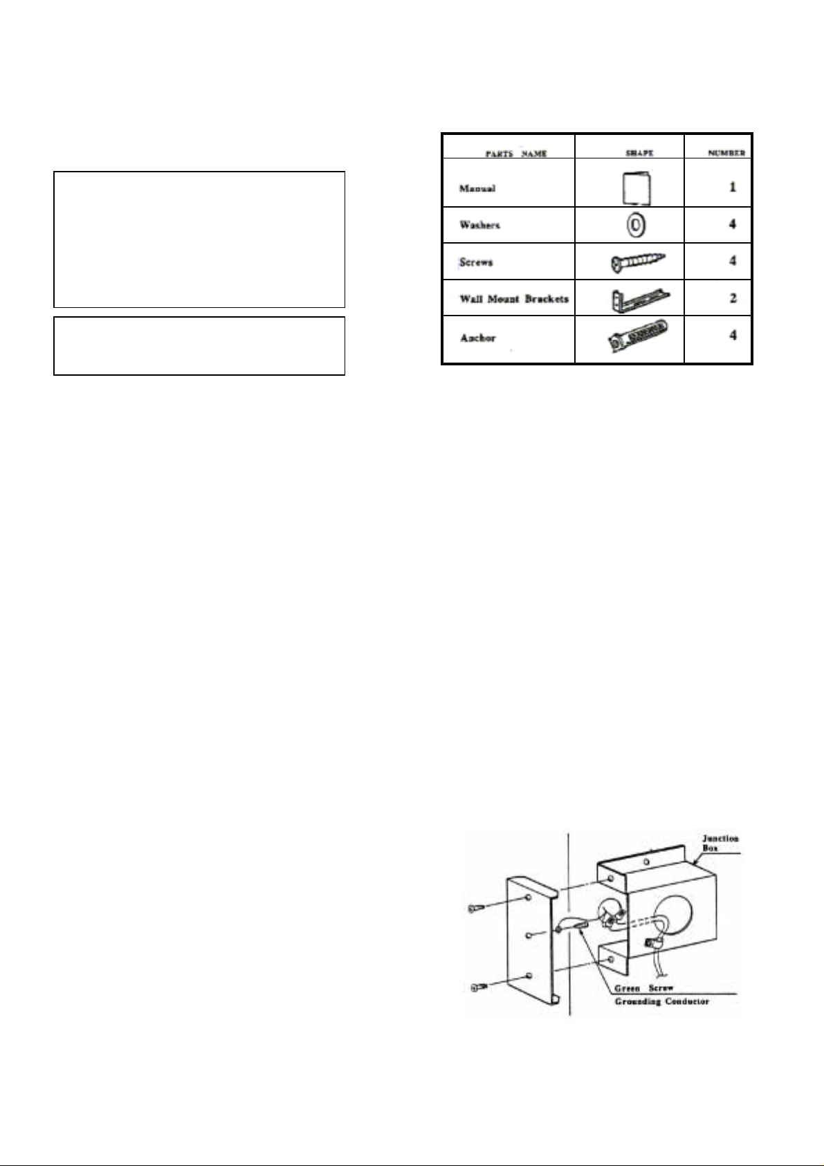
Accessories
Check that all the parts listed below were
included with the unit.
Electrical Connections
The T-K2 requires a 60 Hz 120 VAC electrical
power supply, and it should be properly
ground ed in accordance wit h the most rec ent
edition of the National Electrical Code,
ANSI/NFPA 70 and any local codes. In
Canada, all electrical wiring to the heater
should be installed in accordance with the
Canadi an Electri cal Code, CSA C22.1 Part 1,
and any l ocal c odes. Do not r ely on the g as or
water piping to ground the metal parts of the
heater.
CAUTION: Label all wires prior to
disconnection when servicing controls. Wiring
error can cause improper and dangerous
operation. Verify proper operation after
servicing.
• A means for switching off the 120 VAC
power supply must be pr ovided.
Wire the heater exactly as shown in the
•
wiring diagram.
A green screw is provided in the junction
•
box for the grounding connection.
Page 7
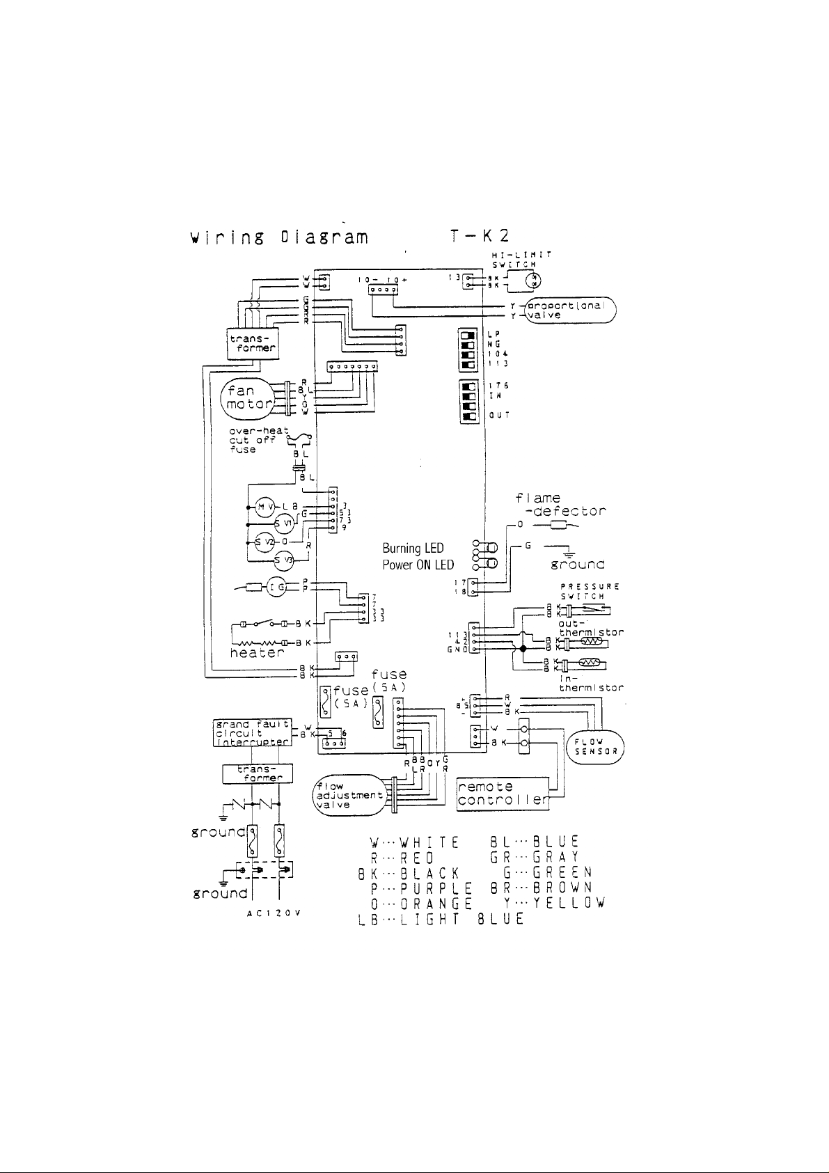
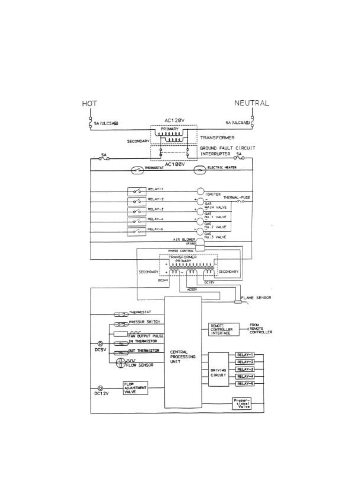
Refer to the following wiring diagrams. Wiring
diagrams are also printed on the inside panel
Wiring Diagrams
of the appliance.
Elect r ical Rat ing
120 VAC, 60 Hz, 0.8 A.
Note : I f a n y of t he o ri gi n al wi ring sup pl i e d w i th th i s ap pl i ance mus t be r epl ac e d, i t m u st be r epl aced
with appliance wiring material (180c) or its equivalent. Wires are available through the manufacturer.
Page 8
Page 9

Page 10
Gas Supply Piping
Check the rating plate to make sure that the
unit was built for the type of gas available in
the area.
The gas supply piping should be sized
according to the Applicable Plumbing Code for
a maximum draw of 185,000 BTUH. First
determine the effective length of the gas
supply line by measuring the actual length of
piping, and then adding 5 f t. f or ev ery elbow or
“T” to the actual length. Use the charts below
to determine the pipe diameter necessary to
accommodate the BTU demand of the unit. If
there are more gas drawing appliances on the
line, si ze a cco r din g to the ma xi mu m amoun t o f
BTU demand.
The gas supply pressures must be within the
ranges of the following chart:
Natural Gas
Supply Pressure
Propane Gas
Supply Pressure
Insufficient gas supply pressure can cause the
Flash Water Heater to lose efficiency or not
work at all.
Min. 5” WC
Max. 10.5” WC
Min. 11” WC
Max. 14” WC
WARNING: Fire or e xplosio n may resul t if the
maximum supply pressures are exceeded.
The manifold gas pressure should be at
maximum 2.3” WC for natural gas, and 2.5”
WC for propane.
Always use approved connectors to connect
the unit to the gas line. Always purge the gas
line of any debris before connecting to the
water heater.
WARNING: Conversion of this unit from
natural gas to propane or propane to natural
gas cannot be done in the field. Contact your
local retailer or distributor to get the correct
unit for your gas type.
Always install a manual shutoff valve on the
gas supply line in case of an emergency, or if
service or maintenance is necessary.
This appliance and its individual shut-off valve
must be isolated from the gas supply piping
system by unplugging the unit and turning off
the main gas valve during any pressure testing
of the gas supply piping system at test
pressures equal to or less than ½ PSI.
When all of the connections have been made,
check the gas line for leaks. Apply soapy
water to all gas fittings and connections, if
bubbles form, there may be a leak.
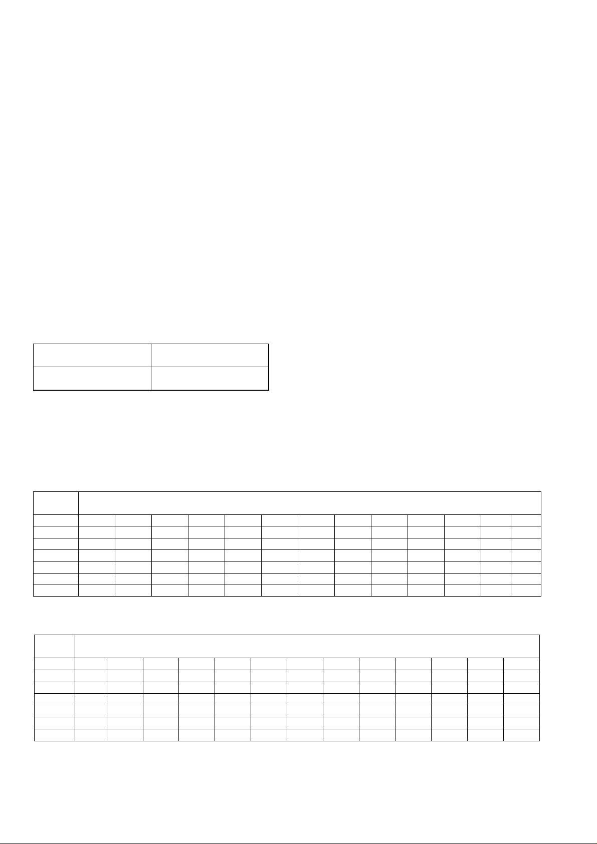
Natural Gas Supply Piping
Based on 0.60 specific gravity for natural gas at .5” WC pressure drop
DOE standard is 1100 BTU per cubic ft. of natural gas
Pipe
Size
Length 10’ 20’ 30’ 40’ 50’ 60’ 70’ 80’ 90’ 100’ 125’ 150’ 200’
½” 174 119 96 82 73 66 61 56 53 50 44 40 34
¾” 363 249 200 171 152 138 127 118 111 104 93 84 72
1” 684 470 377 323 286 259 239 222 208 197 174 158 135
1 ¼” 1404 965 775 663 588 532 490 456 428 404 358 324 278
1 ½” 2103 1445 1161 993 880 798 734 683 641 605 536 486 416
2” 4050 2784 2235 1913 1696 1536 1413 1315 1234 1165 1033 936 801
Cubic Feet of Natural Gas
Propane Supply Piping
Based on 11” WC supply pressure
Pipe
Size
Length 10’ 20’ 30’ 40’ 50’ 60’ 70’ 80’ 90’ 100’ 125’ 150’ 200’
½” 275 189 152 129 114 103 96 89 83 78 69 63 55
¾” 567 393 315 267 237 217 196 185 173 162 146 132 112
1” 1071 732 590 504 448 409 378 346 322 307 275 252 213
1 ¼” 2205 1496 1212 1039 913 834 771 724 677 630 567 511 440
1 ½” 3307 2299 1858 1559 1417 1275 1181 1086 1023 976 866 787 675
2” 6221 4331 3465 2992 2646 2394 2205 2047 1921 1811 1606 1496 1260
kBTU of Propane
Page 11
Water Plumbing
Follow local guidelines for the length of the
plumbing line in order to ensure that there is
enough water pressure for all the fixtures on
the line. First, calculate the effective length of
the plumbing line by measuring the total length
of pipe, and then adding to this 5’ for each
elbow or tee in the line. Use the following
chart to determine the total number of fixture
units on the line, and then compare with the
chart at the bottom of this page to find the pipe
diameter and water pressure necessary.
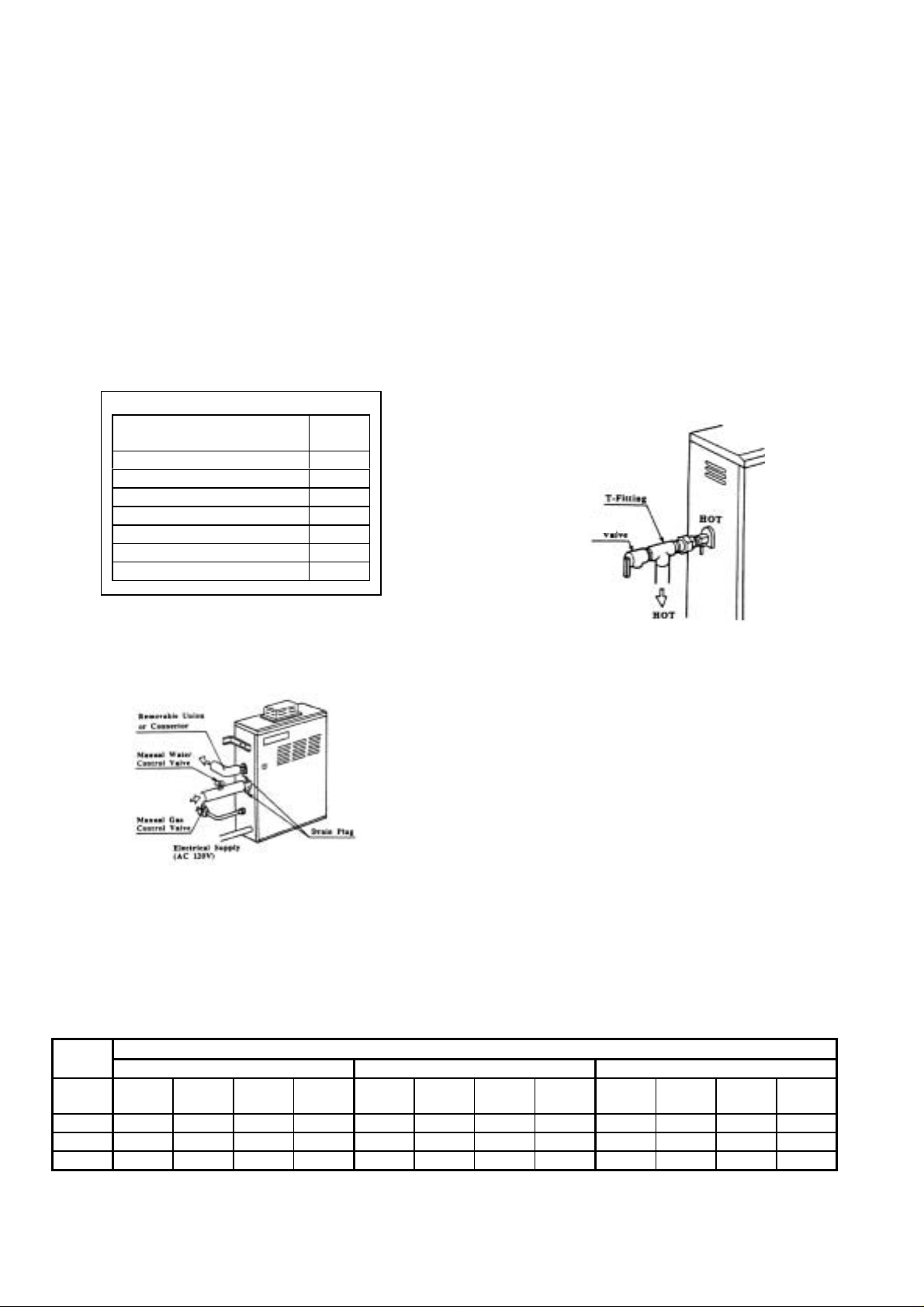
Install with control valves on the inlet and
outlet, and use removable unions or
connec tor s t o f acil it at e ma int enanc e or s ervi c e
if necessary.
If the water heater is installed in a closed
water system, means shall be provided to
control thermal expansion. Contact the water
supplier or a local plumbing inspector on how
to control this situation.
Purge the water line of air, and clean the filter
before initial operation.
Fixture Unit Per Fixture (from UPC)
Plumbing Fixt ur e
Description
Combination Bath / Shower 4
Whirlpool Bath 4
Shower 2
Lavatory 1
Clothes Washer 4
Dishwasher 1.5
Kitchen Sink 1.5
Fixture
Unit
WARNING: Do not reverse the hot outlet and
cold supply line connections to the Flash
Water Heater. Make sure the hot and cold
lines are connected as in the FOR YOUR
SAFETY section at the front of this manual.
Pressure Relief Valve
An approved pressure relief valve must be
installed in any installation with this unit. The
pressure relief valve must be installed on the
hot line out of the unit, with no check valves or
control valves between the unit and the relief
valve.
The Pressure relief valve must be rated for
150 PSI, and have a discharge capacity of
185,000 B TU. Conn ec t th e disc har ge o pe ning
of the relief valve to a suitable drain to prevent
water damage should discharge occur.
If the pressure relief valve discharges
periodically, this may be due to thermal
expansion in a closed water supply system.
Contact the water supplier or local plumbing
inspector on how to correct this situation.
Do not plug th e press ure reli ef val ve. The l ine
should have no reduced fittings or other
restrictions and should allow for complete
draina ge of va lve and line. T he pres sure rel ief
valve should be manually operated once a
year to check for correct operation.
Should overheating occur or the gas supply
fail to shut off, turn off the manual gas control
valve to the appliance.
Pipe
Size
3/4"
1"
1-1/4"
Length to the End of Hot Water Line and Recommended Fixture Units
Pressure Range 30 to 45 PSI Pressure Range 46 to 60 PSI Pressure Range 60+ PSI
100' 200' 300' 400' 100' 200' 300' 400' 100' 200' 300' 400'
3-12 1-6 1-5 0-4 5-17 3-11 2-8 1-6 6-20 4-13 3-10 2-8
12-25 6-17 5-13 4-12 17-36 11-25 8-20 6-18 20-39 13-32 10-26 8-22
25-48 17-32 13-25 12-21 36-78 25-52 20-39 18-33 39-78 32-74 26-54 22-43
Page 12
Wall Hanging Instal lation
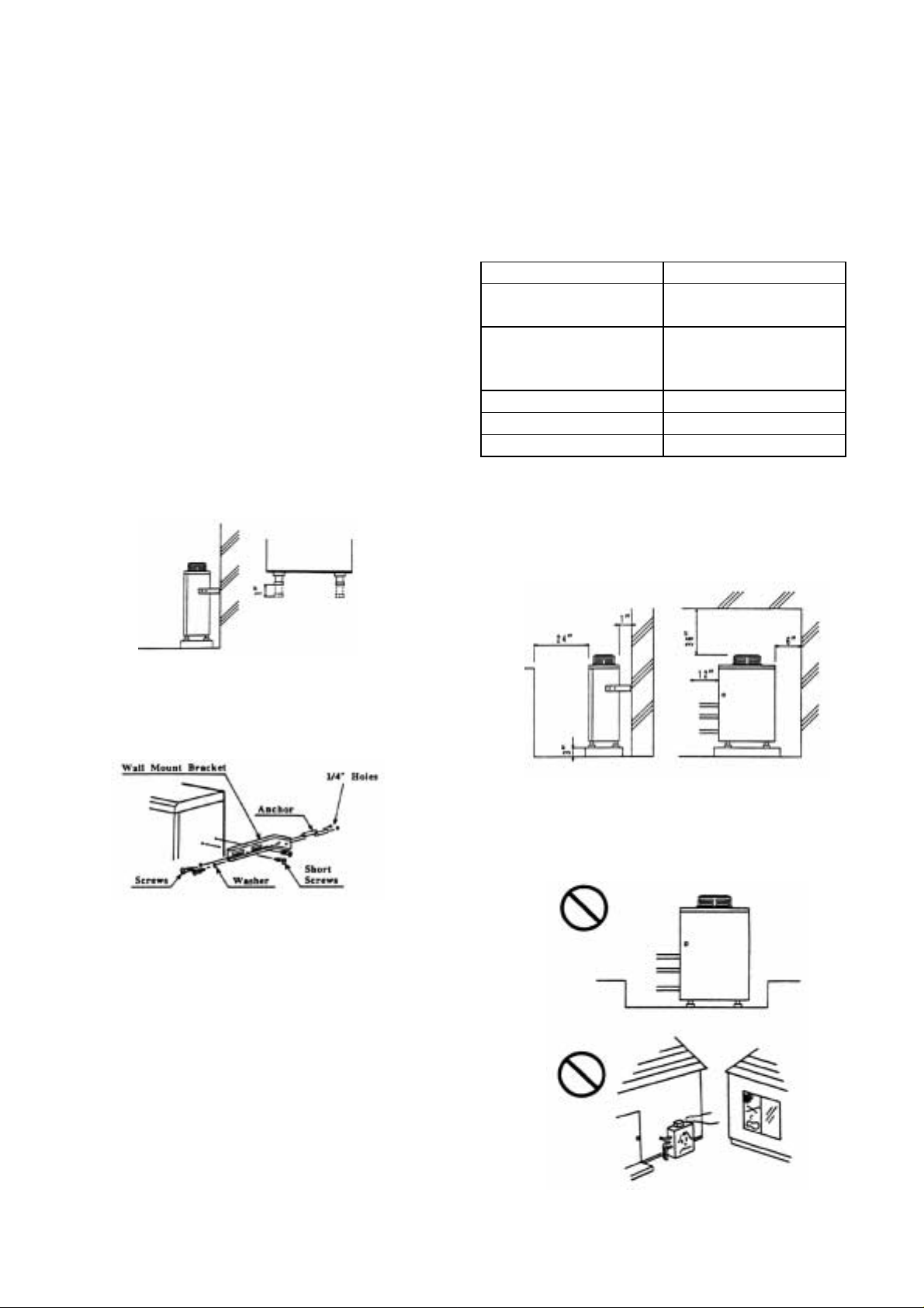
For a wall mount installation, use TK-BK01
brackets to securely attach the T-K2 to the
wall.
Locate the heater as desired, but follow all
applicable local codes, as well as t h e indoor o r
outdoor clearances that apply to the
installation.
Standing Installation
If the unit is to be installed standing on a
surfac e, adj ust th e leg s so that t he uni t stan ds
securely and is level (legs can be adjusted up
to 1”).
Do not install the unit standing directly on a
combustible surface. Use a 3” noncombustible base.
Locate t he water heat er in an ope n, unroofed
area, and maintain the following minimum
clearances from combustible and
noncombustible materials.
Outdoor Clearances
Piping side 6”
Front (Maintenance
space)
Floor Non combustible
base Min. 3” off the
Back of he ater 1”
Non piping side 2”
Top of heater 36”
If this unit is installed under an overhang,
there must be a 36” clearance from the top of
the unit to the overhang, and the surrounding
area must be open in front and on the sides of
the unit.
24”
ground
Use the included L brackets to connect the
unit to a wall to ensure that it does not fall over.
These brackets will maintain the required 1”
clearance between the back of the unit and a
combustible surface.
Outdoor Installation
Follow all local codes, or in the absence of
local codes, follow the codes for Installation of
Gas Burning Appliances; National Fuel Gas
Code ANSI Z221.23 in USA or CAN/CGA
B149.1 or .2 in Canada.
For outdoor installation, purchase a TK-TV04
and install on the top of the unit.
Set the dipswitches for an outdoor installation
(See pgs . 21-22) .
WARNING: Do not have the flue terminal
pointing toward any opening into a building.
Do not locate your heater in a pit or any
location wher e g as a n d water can accumulate.
Page 13
WARNING: Do not install the heater where
water, debris, or flammable vapors may get
into the flue terminal. This may cause damage
to the heater.
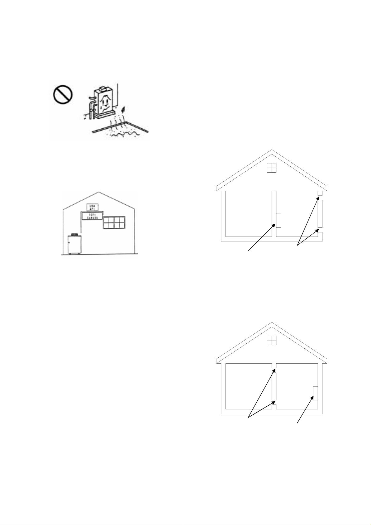
WARNING: United States regulations forbid
insta lling th e unit wit hin 4’ of any openi ng into
any building. Similar Canadian regulations
forbid the unit from being installed within 10’ of
any opening into any building.
Combustible Air Supply
The T-K2 must be installed in a location where
the proper amount of combustible air will be
available to it at all times. If the unit is
installed in a confined space, there must be
permanent openings supplying air to the unit.
If the openings will bring air directly from the
outdoors, two openings are required, and they
should be sized to give a minimum free area
of one square inch for every 4000 BTUH of the
maximum input rating of the unit.
WARNING: Improper installation can cause
nausea or asphyxiation from carbon monoxide
and flue gases which could result in severe
injury or death.
For installation in altitudes above 4,500 feet,
contact the manufacturer for instructions.
Indoor Installation
Follow all local codes, or in the absence of
local codes, follow the codes for Installation of
Gas Burning Appliances; National Fuel Gas
Code ANSI Z221.23 in USA or CAN/CGA
B149.1 or .2 in Canada.
WARNING: In an indoor installati on, the T-K2
must be connected to a Category III special
gas vent in order to direct the dangerous
exhaust byproducts to the outdoors.
Connec t the 4” Cate gory I II ven t pipe t o the 4 ”
round collar on t h e t o p of the uni t .
WARNING: Do not install the unit directly on a
combustible surface such as carpeting, wood
floors, etc. If it is necessary to install the unit
standing on a surface, install a 3”
noncombustible base between the unit and the
surface.
Air Vents
T-K2 (47 sq. in.
each)
If the openings will bring air from another
indoor area, they should be sized to give a
minimum free area of one square inch for
every 10 0 0 B T UH of the ma xi m um in put r ating
of the unit.
Air Vents
(185 sq. in. T-K2
each)
One of these openings should be wi thin 12” of
the ceiling, and the other should be within 12”
of the floor.
Page 14
Exhaust Venting
This water heater must be vented in
accordance with the section on venting of
equipment in the latest edition of the National
Fuel Gas Code.
This is a Category III appliance, and must be
vented accordingly. The following are UL
listed manufacturers: ProTech Systems
FasNSe al, Z-Fl ex Inc. Z-V ent II and He at-Fab
Inc. Saf-T Vent. This unit requires 4” vent pipe.
Connect the vent pipe to the unit so that it is
sealed airtight. Follow the vent pipe
manuf acturer ’s in struct ions wh en ins talli ng the
vent pipe. Do not common vent this appliance
with any other vented appliance.
The venting system must not exceed a length
of 35 ft. minus 5 ft. for every elbow. Do not
use more than 3 elbows.
No. of Elbows Max. Vertical or
Horizontal Length
0 35 ft.
1 30 ft.
2 25 ft.
3 20 ft.
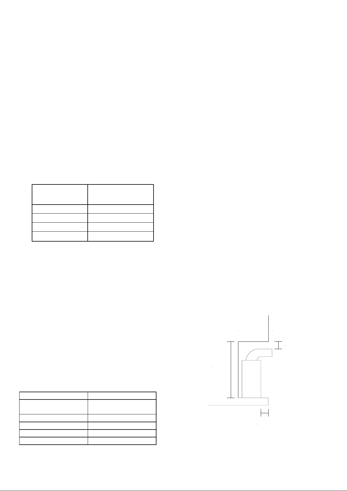
If the horizontal vent run exceeds 5 ft., the
following criteria must be observed:
• There must be a 2” vertical run off the
top of the heater before the horizontal
run begins.
• The horizontal run must be supported
at 3’ intervals.
• The vent run should be pitched up
towards the termination at ¼” per foot.
The unit can be vented either up and out the
roof, or directly through a wall. If the unit will
be vente d t hr ou gh a w al l , us e T ak ag i US A Inc .
option al part, the TK-TV01 ve nt termin ator, or
an equal Category III vent part. Locate the
vent terminator according to ANSI
Z223.1/NFPA 54 and applicable local codes.
Maintain the following clearances to any
combustible surface in an indoor installation:
Indoor Clearances
Piping side 6”
Front (Maintenance
space)
Floor
Back of heater 1”
Non piping side 2”
Top of heater 12”
Suggested 24”
Min. 4”
Noncombustible base
Manufactured Home (Mobile Home)
Installation
This appliance must be installed in
accordance with the Manufactured Home
Construction and Safety Standard, (Title 24,
CFR; Part 3280) and ANSI A119.5/NFPA
501D. In addition, install in accordance with
the following instructions, the instructions
supplied with any venting, local codes, utility
company requirements for the installation of
water heaters in manufactured homes (mobile
homes), and the latest edition of the National
Fuel Gas Code, ANSI Z221.3/NFPA 50.
Locate the heater in an enclosure separating
the unit from the internal atmosphere of the
manuf actured hom e or trai ler. All c ombustion
air must be obtained from the outside
atmosphere, and the flue gases must be
discharged directly outdoors through a gas
vent. There must be no opening from the
interior of the home or trailer into the water
heater enclosure.
Indoor Installation
Follow indoor installation instructions as set
out in an earlier section of this manual, except
that combustion air must not be taken from the
inside of the home or trailer.
Outdoor Installation
Follow outdoor installation instructions as set
out in an earlier section of this manual.
If the unit is to be installed in a recessed area,
connect a gas vent to the unit, which will direct
exhaust gases o ut of the rec es s ed area.
Indoors Outdoors
Min. 3"
Min. 32"
Min. 3"
Page 15
Initiating the A ppliance
For your safety, read before operating.
WARNING: If you do not follow these
instructions exactly, a fire or explosion may
result causing property damage, personal
injury or loss of life.
a) This appliance does not have a pilot. It is
equipped with an electronic ignition device,
which automatically lights the burner. Do
not try to light the burner by hand.
b) Before operating, check for gas
accumulation in the area around the
appliance. Pay special attention near the
floor, because gas is often heavier than air,
and it may accumulate near the floor.
c) Do not attempt to open the manual gas
shutoff valve with anything but by hand.
Never use tools. If the valve will not open
by hand, do not try to repair i t. Instead, call
a qualified service technician. Force or
attempted repair may result in a gas leak,
fire or explosion.
d) Do not use this appliance if any part has
been under water. Immediately call a
qualified service technician to inspect the
appliance and to replace any part t hat may
have been damaged by being under water.
WARNING: IF YOU SMELL GAS:
• Do not use any applianc e.
• Do not touch any electric switch, do not
use any phone in your building.
• Immediately call your gas supplier from a
neighbor’s phone. Follow the gas supplier’s
instructions.
• If you cannot reach your gas supplier, call
the fire department.
Initial Operation
1. S TOP! Do not op erate witho ut reading t he
safety information first!
2. Switch off the electrical power supply to the
heater.
3. Do not attempt to light the burner manually.
4. Turn the manual gas control valve located
on the outside of the unit counterclockwise
to the OFF position.
5. W ait five (5) minutes to clear out any gas.
If you t hen smell gas, STOP ! Follow “ b” in
the “Initiating the Appliance” section above.
If you do not detect gas, proceed to the
next step.
6. Turn the manual gas control valve located
on the outside of the unit clockwise to the
ON position.
7. Turn on the electrical power to the
appliance.
8. Turn on any tap, and the T-K2 will initiate
itself.
9. If the appl iance wil l not operat e, foll ow the
instructions in the “Turning Off the Gas
Supply to the Appliance” section following,
and call a service technician or gas
supplier.
TURNING OFF THE GAS SUPPLY TO THE
APPLIANCE
Close the manual valve on the gas inlet line.
Turn off the power supply.
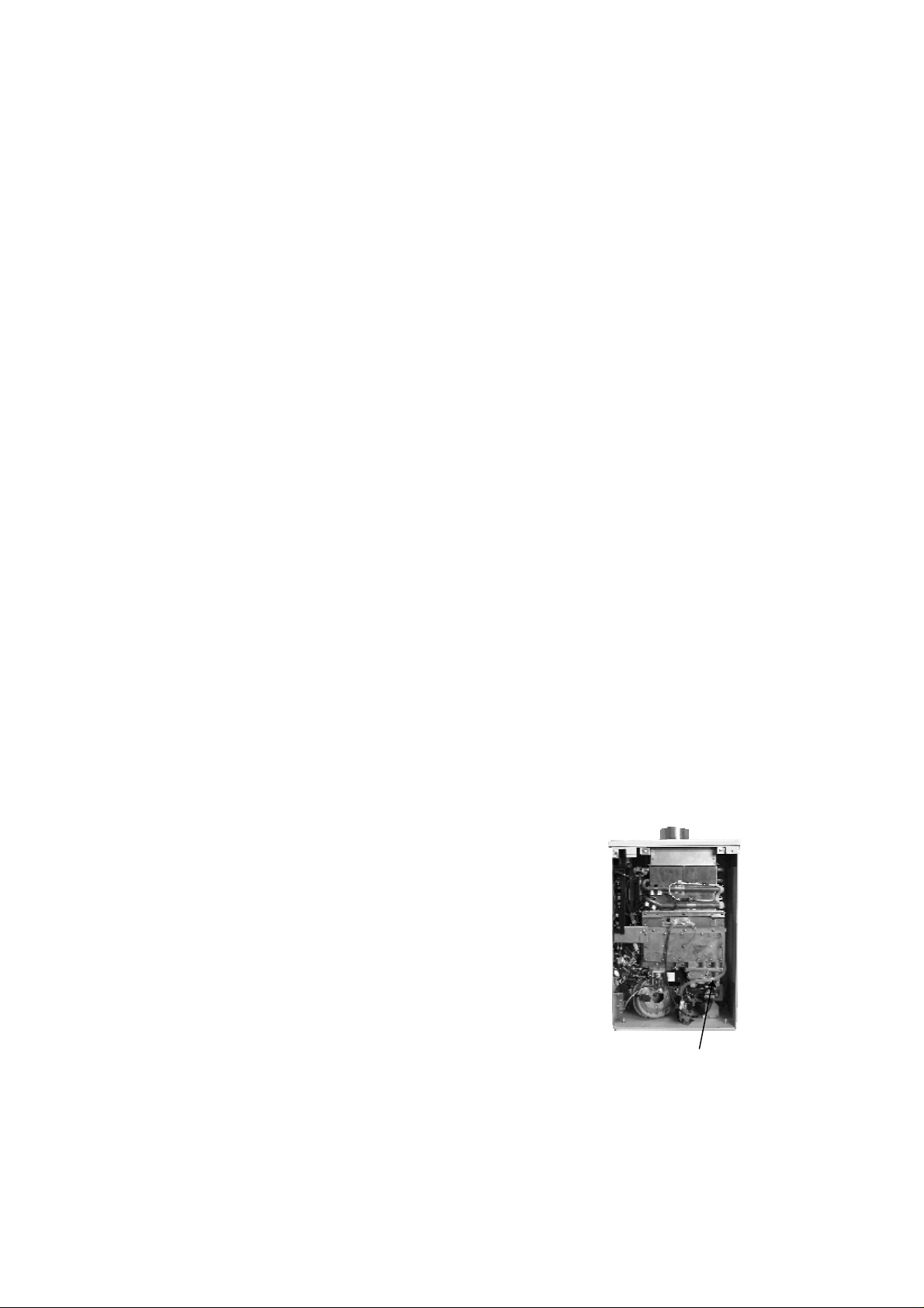
Manifold pressure tap.
Page 16

p
Space Heating Application
The FLASH T-K2 can be used for space heating as well as potable heating of hot water
applications.
WARNING
• Toxic chemicals such as used for boiler treatments chemical, alcohol,
glycerol and gl ycol group will not b e introduced into the s ystem when used
for potable water and space heating.
• The FL ASH T- K2 can be used t o supp ly pot able w ater a nd spa ce heat ing an d
shall not be connected to any heating system or component(s) previously
used with non-potable water where any chemicals were added to the water
heating appliances.
• When the system requires water for space heating at temperatures higher
than required for other used, a means such as a mixing valve shall be
installed to temper the w ater for those uses in order to reduce scald hazard
potential.
• Water temperature over 125 °F can cause severe burns instantly or death
from scal d s.
• Chemicals such as d iluted Glycol can be used for radiant floor, Hydro-warm
air or Baseboard heating only.
Basic system drawings and Schematics.
Heating application onl y:
Pressure Relief Valve
Air Vent
Pum
Expansion Tank
Radiant, Hydro or Baseboard
Heating Equipme nt.
Make up Water Supply
Warning: This illustration is for concept only. There are a wide variety of variations to the
application of controls and equipment presented applications. Designers must add all
necessary safety and auxiliary equipment to conform to code requirements and design
practice.
For more details, contact Technical Department at (888) 882-5244
Page 17
y
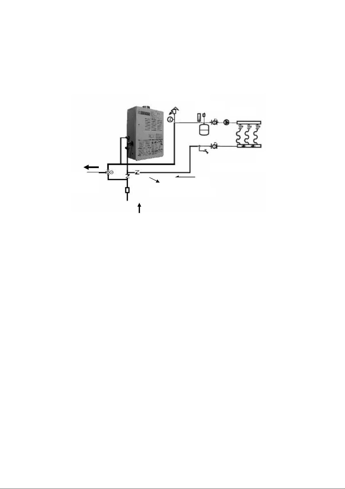
Dual-p u r pose ho t water he at ing (Do m estic an d Heating):
Pressure Relief Valve
Domestic
potable water
Air Vent
Expansion Tank
Check Valve
Priority Control Devices
Pump
Radiant, Hydro or Baseboard
Heating Equipme nt.
Cold water suppl
Priority Control Devices: It has a capability to make priority system that can be used as a
controller flow sensor, Aquastat, or electronic controller to controlling radiant, Hydro or
baseboard heating equipments.
Warning: Follow all local codes, or in the absence of local codes, follow the most recent
edition of the National Standard Code, ANSI Z21. 10.3.
Warning: This illustration is for concept only. There are a wide variety of variations to the
application of controls and equipment presented applications. Designers must add all
necessary safety and auxiliary equipment to conform to code requirements and design
practice.
For more details, contact Technical Department at (888) 882-524
Page 18
FOR YOUR SAFETY READ BEFORE OPERATING
WARNING: If you do not follow these instructions exactly, a fire or
explosion may result causing property damage, personal injury or loss of
life.
A. This water heater does not have a pilot. It is equipped with an ignition device that
automatically lights the burner. Do not try to light the burner by hand.
B. BEFORE OPERATING smell all around the water heater area for evidence of
leaking gas. Be sure to smell next to the floor because some gas is heavier than air
and will settle on the floor.
WHAT TO DO IF YOU SMELL GAS.
• Do not try to light any appliance.
• Do not touch any electric switch, do not use any phone in your building
• I mmediat ely call your gas su pplier f rom a ne ighbor's phone. Fol low th e gas
supplier's instructions.
• If you cannot reach your gas supplier, call the fire department.
C. Use only your hand to turn the gas val ve knob. Never use tools. If the knob will not
turn by hand, don't try to repair it. Call a qualified service technician. Force or
attempted repair may result in a fire of explosion.
D. Do n ot use this water heat er if an y part has be en under wat er. Imme diately cal l a
qualified service technician to inspect the water heater and to replace any damaged
parts.
OPERATING INSTRUCTIONS
1. STOP! Read the safety information above or in the Owners Manual.
2. Turn off all electric power to the water heater.
3. Do not attempt to light the burner by hand.
4. Turn the gas manual gas valve located on the outside of the unit clockwise ↻ to the
off position.
5. Wait five (5) minutes to clear out any gas. If you then smell gas. STOP! Follow "B"
in the safety information above on this label. If you don't smell gas, go to next step.
6. Turn the manual gas valve located on the outside of the unit counter clockwise ↺ to
the ON position.
7. Turn on all electrical power to the water heater.
8. If the water heater will not operate, follow the instructions " to Turn Off Gas to water
heater" and Call your service technician or gas supplier.
TO TURN OFF GAS TO APPLIANCE
1. Turn off all electric power to the water heater if service is to be performed.
2. Turn th e manu al gas val ve loca ted o n the o uts ide of the uni t clo ckwis e ↻ to the off
position.
Page 19
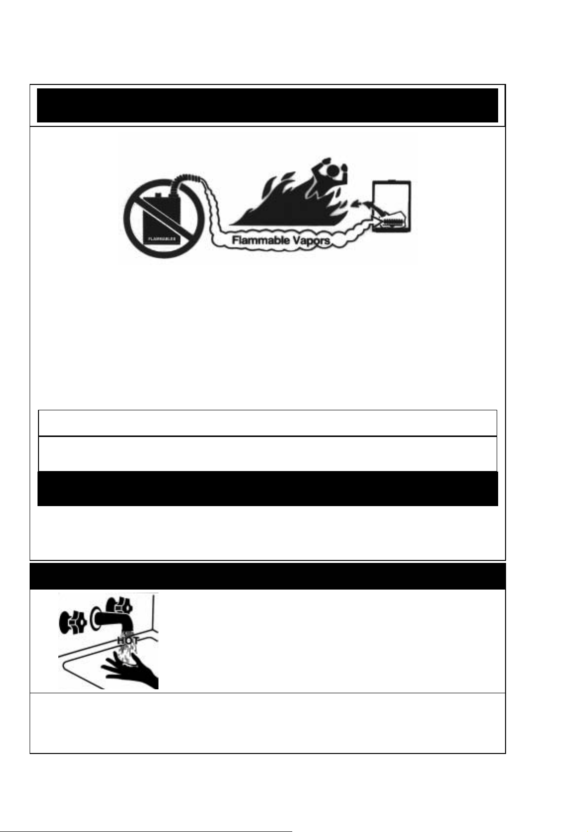
DANGER
Vapors from flammable liquids will explode and catch fire causing death or severe burns.
Do not use or store flammable products such as gasoline, solvents or adhesives in the
same room or a r ea near th e wa ter heater.
Keep fl a mmable pr o d ucts:
1. Far away from heater.
2. In approve d containers.
3. Tightly closed
4. Out of children's reach
WARNING: Do not install water heater where flammable products will be stored.
Read and follow water heater warnings and instructions. If owner's manual is
missing, contact the retailer or manufacturer.
WA RN I N G
The outlet hot water temperature of the T-K2 water heater is factory set 120 °F.
WARNING: Use this heater at your own risk. The set outlet water temperature can cause
severe burns instantly or death from scalds. Test the water before bathing or showering.
DANGER
Hot Water Heater temperature over 125 °F can cause
severe burns instantly or death from scalding.
Children, disabled and elderly are at the highest risk of
being scalded.
Feel water temperature before bathing or showering.
Temperature limiting valves are available, ask professional
person.
WARNING: California Proposition 65 lists chemical substances known to the state to
cause cancer, birth defects, death, serious illness or other reproductive harm. This product
may contain such substances, be their origin from fuel combustion (gas, oil) or
components of the product itself.
Vapors:
1. Cannot be seen
2. Vapors are heavier than air
3. Go a long way on the floor
4. Can be carried from other rooms
to the main burner by air currents.
Page 20
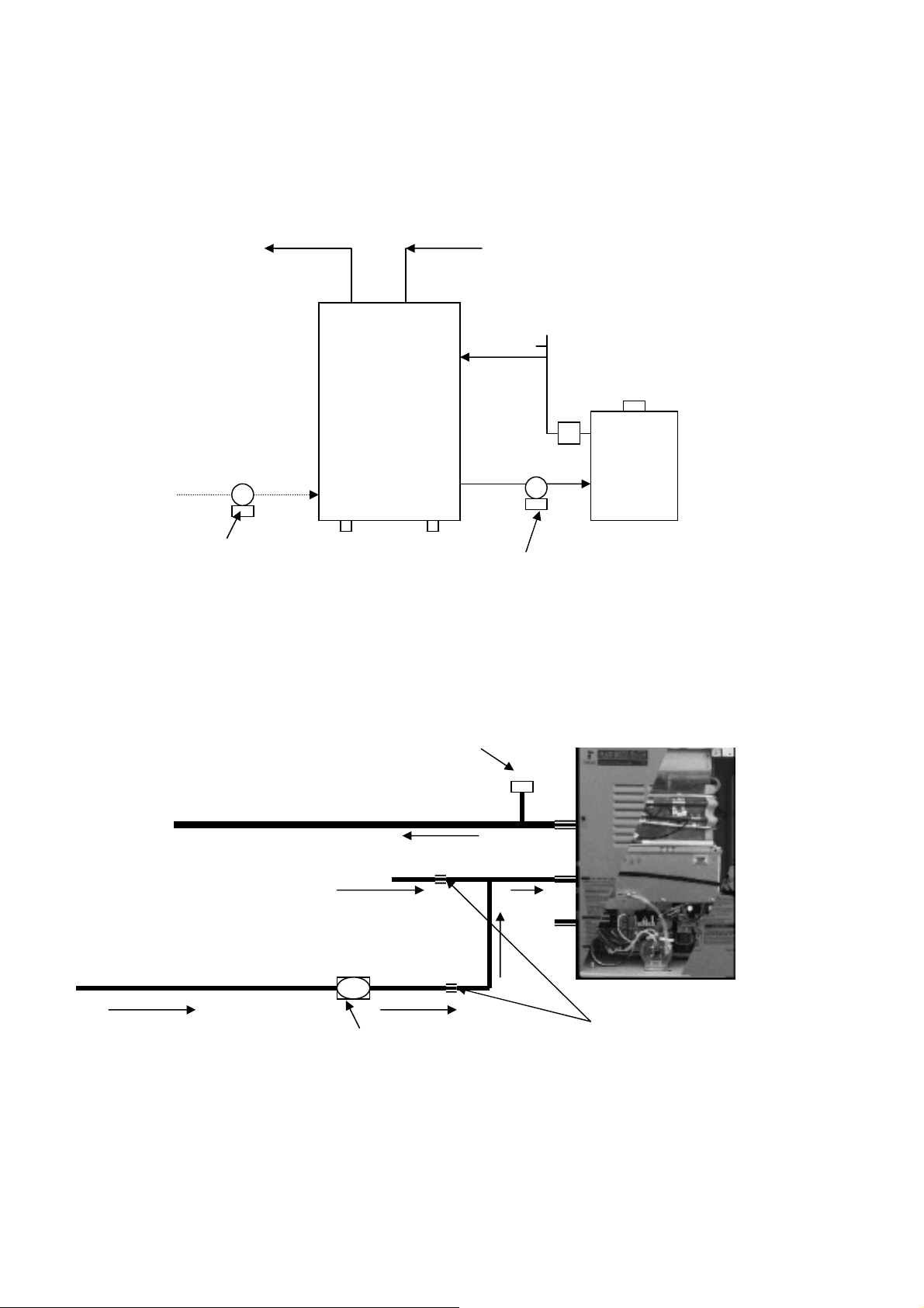
Applications
The T-K 2 c an b e i nst all ed in a v a rie ty of pl um bi ng a ppl ic ati ons , wh ich wi ll prov id e mo re com for tab le
domestic hot water. Contact Takagi for information on using this unit as a heat source.
T-K2 with Storage Tank
Hot Out Cold In
Relief Valve
Valve
Hot Water
Recirculation
Recirc. Pump Pump
The maxi mum flow rat e thro ugh t he T-K 2 is 6.9 GPM . If it is necess ary to ac hiev e hig her f low rat es
for l onge r p er i od s of ti m e, t hen i t can b e i ns talled i n co nj u nct i on wi th a s t ora g e t an k. A pu m p wi l l be
necessary to keep the water hot. We suggest a pump of 1/12 hp or greater depending on the
system.
Recirculation
Pressure Relief Valve
Hot Water to Hous e
Cold Water Inlet
Hot Water Return
Pump (with/without Timer) Check Valves
This system will also need a pump of 1/12 hp or greater, depending on the application situation.
For more details, contact Technical department at (888) 882-5244
Check
Page 21
Maintenance
WARNING: Turn off the electrical power supply, the manual gas control valve, and the
manual water control valve before servicing.
The unit should be checked once a year or as necessary by a certified and trained technician. If
repairs are needed, the repairs should be done by a certified and trained technician.
The following systems and parts should be checked at least once a year:
1. Venting systems
2. Burners
3. Manual operation of the pressure relief valve to ensure correct operation.
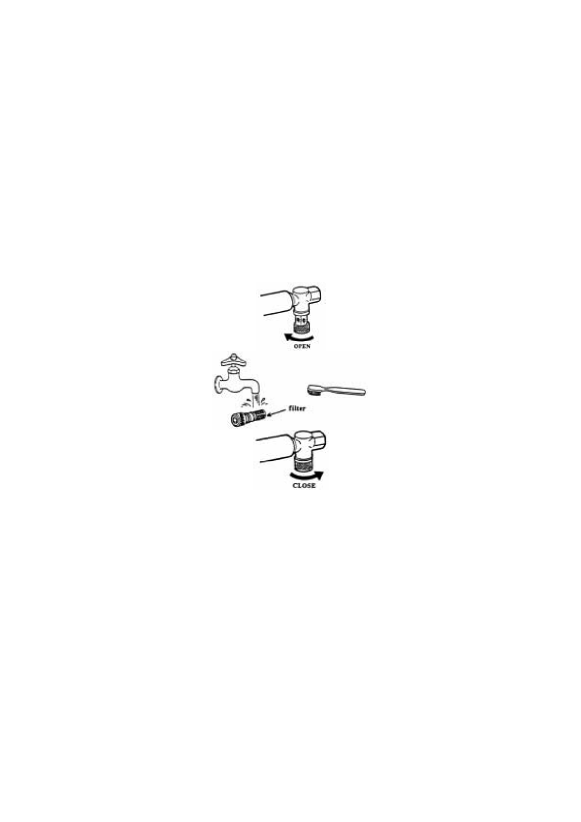
4. Periodic cleaning of the water filter, refer to figure below.
5. Heat exc hanger. Remove t he therm istor a nd check for a mi neral coa ting . A mineral coati ng on
the thermistor requires flushing the heat exchanger with a desc aling solution. Scale build up will
void your warranty and shorten the life of your water heater.
Troubleshooting
Water Isn’t Hot Enough
The T-K2 can burn gas at a maximum input rate of 185,000 BTUH. This puts a limit on the possible
output temperature and flow capabilities (See flow chart on the last page of this manual). If the
water doesn’t seem hot enough, compare the fl ow and temperature that is being attained to the TK2 flow vs. temperature chart. If the unit is not performing according to the chart, first check that the
gas supply line is sized properly, and that the gas pressure is within th e required range. If the gas
line is okay, check the plumbing for mixing valves, thermostatic valves, scald protection, single
handled valves or crossed connections. If the unit is performing in accordance with the flow chart,
then it may be unders ized for the a pplicati on. If the unit is perform ing accordin g to the chart, the
output temperature can be adjusted using the TK-RE01 or with the dipswitches on the unit (See pgs.
21-22)
It Takes Too Long to Get Hot Water
The T-K2 takes three seconds to ignite, and three more to get up to temperature. The rest of the
time needed for hot water to get to a fixture is due to the length of piping bet ween the water heater
and the fixture. If the unit seems to be taking longer than six seconds to initiate, check the filter and
flow sensor for any debris or damage.
Page 22
The T-K2 Will Not Initiate
First check the flow rate through the unit. If the flow is not .75 GPM or greater, the unit will not
initiate. Check the filter and the flow sensor for any debris or damage.
Press the lower green button on t he GFCI i nsi de the unit. If the red light above it does not come on,
then t h e re is a probl e m with t he electrical suppl y t o the unit. If that l i g h t does co m e o n, hit t h e green
reset button above the light, and look for the green light on the circuit plate at the top left of the unit.
If this light is not lit, there is a problem with the electrical connection between the GFCI and the
circuit plate. Contact Takagi Industrial Company for Instructions.
Error Codes
All Takagi units are self diagnostic for errors. If there is a problem with the installation or the unit, it
will give a s ignal , thro ugh a pair o f fl ashing lights on the circ uit pl ate, t o comm unic ate t he sou rce of
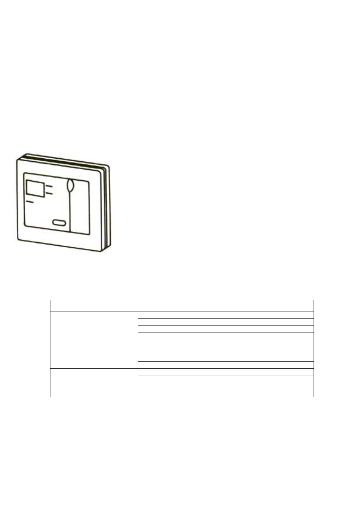
the problem. If the unit has a TK-RE01 remote co ntrol installed, this
will give al so gi ve a n um eri cal error co de. C ons ult the fo ll owi ng c har t
for the meaning of an error code:
TK-RE01
Computer Board
Burning (red) LED: Blinking
Power (green) LED: OFF
Burning (red) LED: OFF
Power (green) LED: Blinking
Blinking Alternately
Blink Simultaneously
TK-RE01 Check Point
11 Igniter
12 Flame Detector
51 Main Gas Valve
72 Pre Post Check
03 Wrong Gas, Dip Switch
14 Hi-Limit Switch
70 Computer Board
71 Proportional Valve
61 Fan Motor Burning LED and Power LED:
21 Vent Pipe
31 Thermistor Burning LED and Power LED:
65 Water Control Valve
For technical support contact Takagi toll free at (888) 882-5244, or check ou r
website at www.takagi-usa.com.
Page 23
Page 24
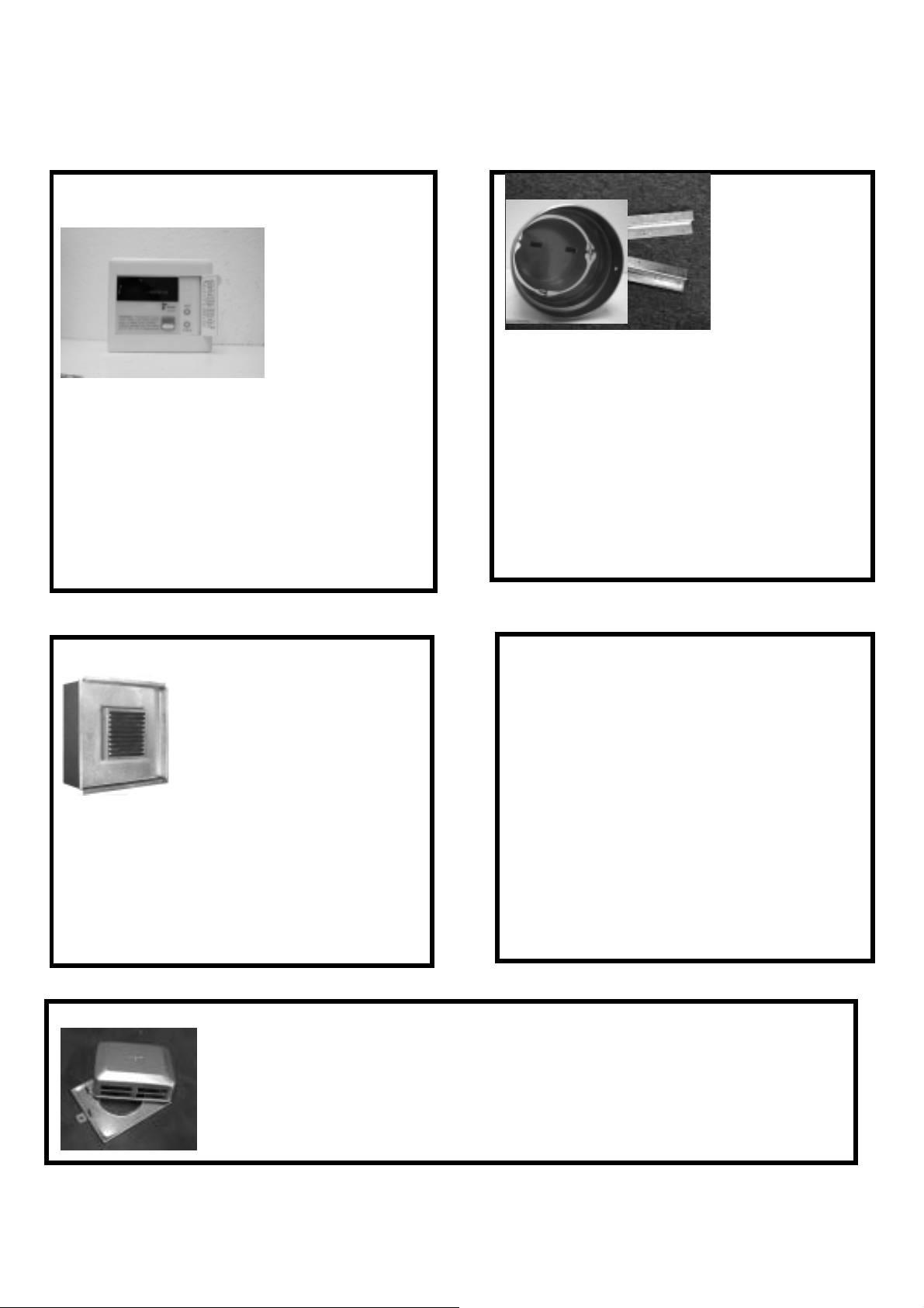
Optional Items
TK-RE01 Temperature Remote
Controller
The TK-RE01
Temperature
Remote Controller
has two functions,
it allows the
maximum output
temperature from
the T-K2 to be
adjust e d wi t hi n th e ra n ge of 95 ° F to 180° F,
and it also works as a diagnostic toll that will
give a c o ncise er r o r code w henever there is a
problem with the unit. The temperature
options are 95°, 100°, 102°, 104°, 106°,
108°, 109°, 111°, 113°, 115°, 117°, 122°,
131°, 140°, 158 °, 167° and 1 80° F. See the
troubleshooting section for information on
possible error codes.
TK-TV01 Vent Terminator
This terminator can be used
where a T-K2 is going to be
vented out through a wall.
This is an CSA approved part
of the unit. Connect a
Category III Special Gas Vent
from the top of the unit to the
backside of this terminator to exhaust flue
gases through the wall without a large
thimble. Install vent terminator in
accordance with manufacturer’s installation
instructions and any applicable codes.
TK-BK01 Wall Mounting Brackets
The TK-BK01
Wall Mounting
Brackets allow
the T-K2 to be
installed hanging
from a wall. It is
not necessary to
earthquake strap
these h eat er s i f t he se br ac ket s a re u s ed. I f
the unit is not going to be mounted on a
wall, the “L” brackets that are included with
every unit will be sufficient as earthquake
protection. Install unit and brackets
according to manufacturer’s installation
instructions and any applicable codes.
TK-TV03 Vent Damper
The TK-TV03 Vent Damper
preven ts th e back fl ow of air
through the exhaust vent.
This is also an CSA
approved part of the unit.
This helps prevent harmful
exhaust gases from
entering the home, as well as helping to
prevent the units from freezing in areas
where cold air can be blown into the exhaust
system. Install vent damper according to
manufacturer’s installation instructions, and
any appl ic ab l e cod es .
TK-TV04 Vent Cap
The TK-TV04 Vent Cap is for outdoor installation with the T-K2 water heater.
The cap is installed on the top of the unit, instead of connecting an exhaust
vent. The cap will prevent any debris that might be in the environment from
entering the unit and causing damage or a fire hazard, as well as preventing
rain or other weather from entering the unit.
Page 25

T-K2 Dipswitch Temperature Settings
In the following dipswitch diagrams, the direction in whic h the head of the dipswitch should
be pointing is represented with black.
Indoor NG Dipswitch Settings
NG Indoor Temperature Settings
4321
ON
4321
112
105
NG
LP
OUT
ON
4321
4321
112
105
NG
LP
OUT
ON
4321
112
105
NG
LP
4321
OUT
ON
4321
4321
112
105
NG
LP
OUT
ON
4321
4321
112
105
NG
LP
OUT
IN
180
ON
IN
180
ON
105° F 112° F 120
Outdoor NG Dipswitch Settings
NG O utdoor Temperature Settings
4321
ON
4321
112
105
NG
LP
OUT
ON
4321
4321
112
105
NG
LP
OUT
ON
° F
ON
IN
180
180
ON
° F
IN
180
IN
180
ON
ERROR
4321
112
105
NG
LP
4321
OUT
ON
4321
4321
112
105
NG
LP
OUT
ON
4321
4321
112
105
NG
LP
OUT
IN
180
ON
ON
IN
180
ON
IN
180
ON
IN
180
IN
180
ON
105° F 112° F 120° F 180° F ERROR
Page 26
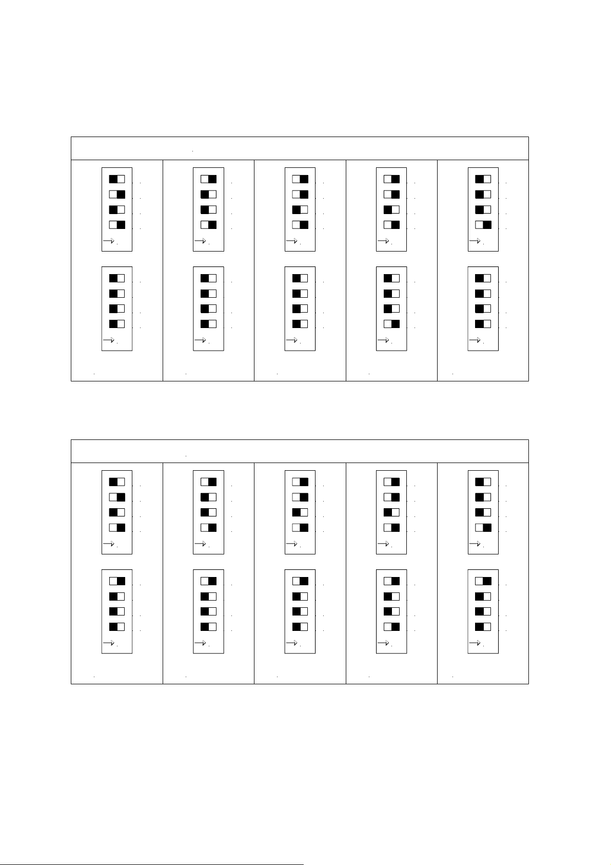
Indoor LP Dipswitch Settings
LP Indoor Temperature Settings
4321
ON
4321
112
105
NG
LP
OUT
ON
4321
4321
112
105
NG
LP
OUT
ON
4321
112
105
NG
LP
4321
OUT
ON
4321
4321
112
105
NG
LP
OUT
ON
4321
4321
112
105
NG
LP
OUT
IN
180
ON
IN
180
ON
105° F 112° F 120° F 180° F ERROR
Outdoor LP Dipswitch Settings
LP Outdoor Temperature Settings
4321
ON
4321
112
105
NG
LP
OUT
ON
4321
4321
112
105
NG
LP
OUT
ON
ON
IN
180
4321
112
105
NG
LP
4321
OUT
ON
ON
4321
4321
IN
180
112
105
NG
LP
OUT
ON
ON
4321
4321
IN
180
112
105
NG
LP
OUT
IN
180
ON
ON
IN
180
ON
IN
180
ON
IN
180
ON
105° F 112° F 120° F 180° F ERROR
IN
180
Page 27
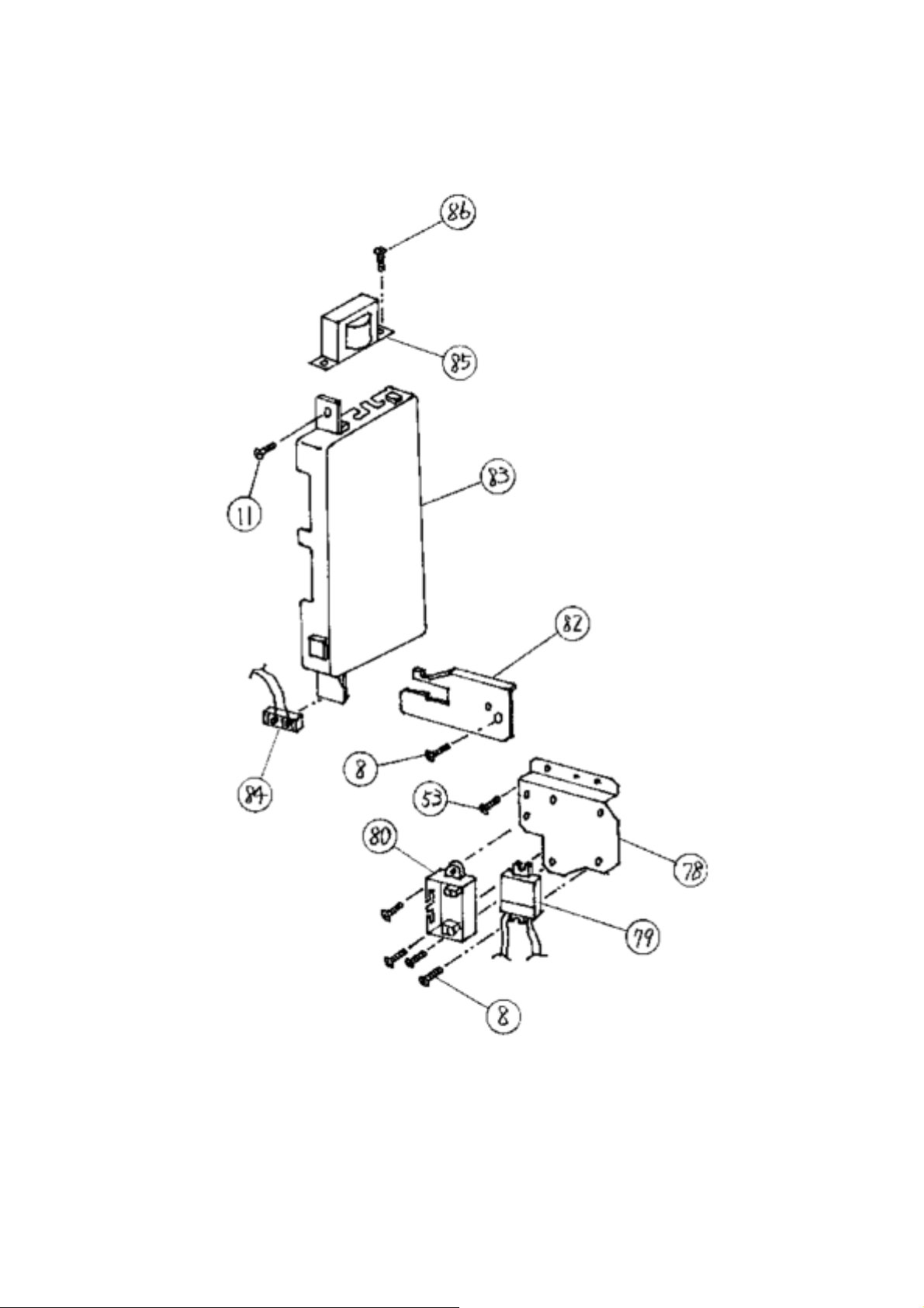
Computer board assembly
Page 28
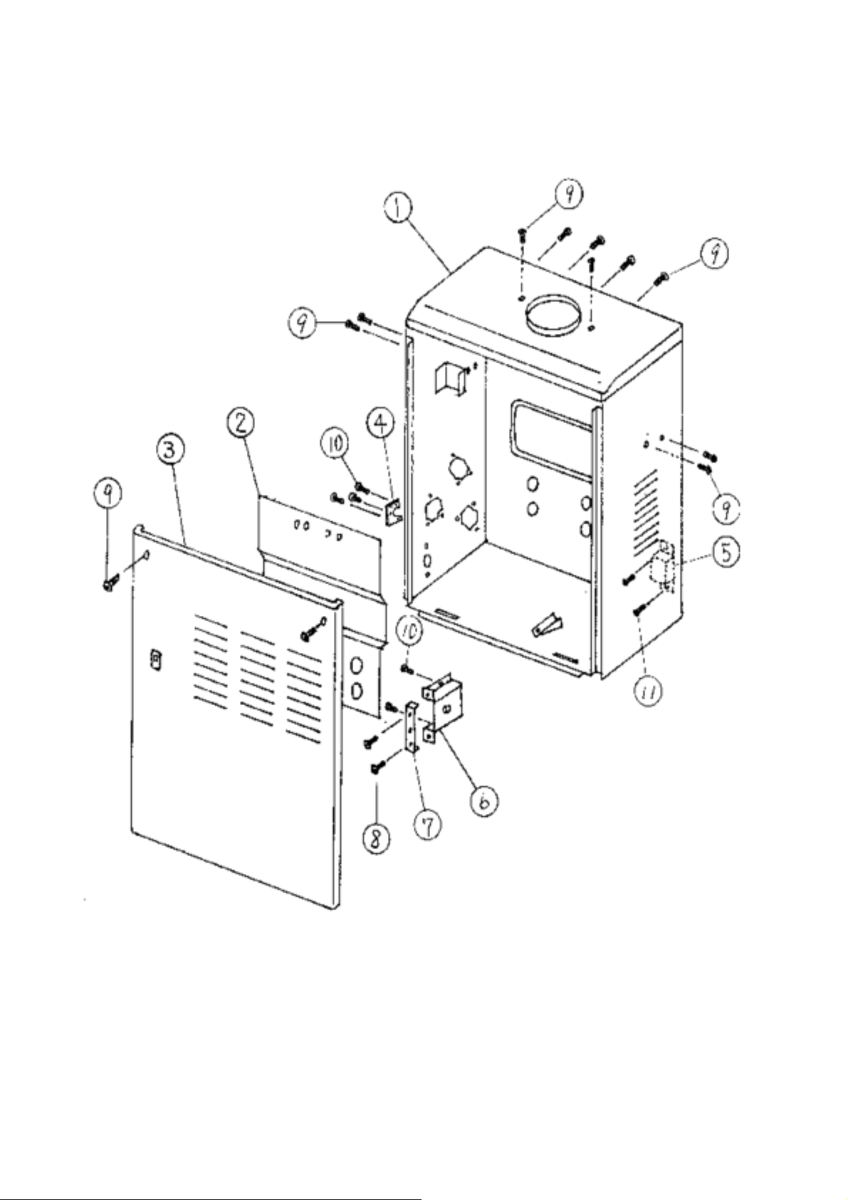
Case assembly
Page 29
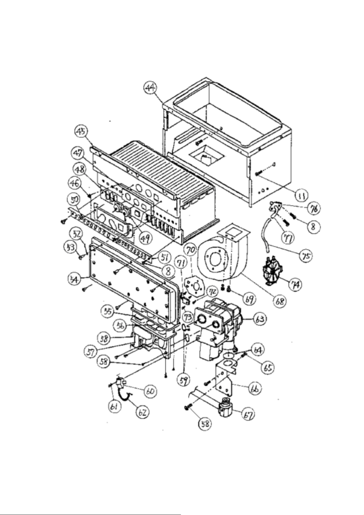
Burner assembly
Page 30
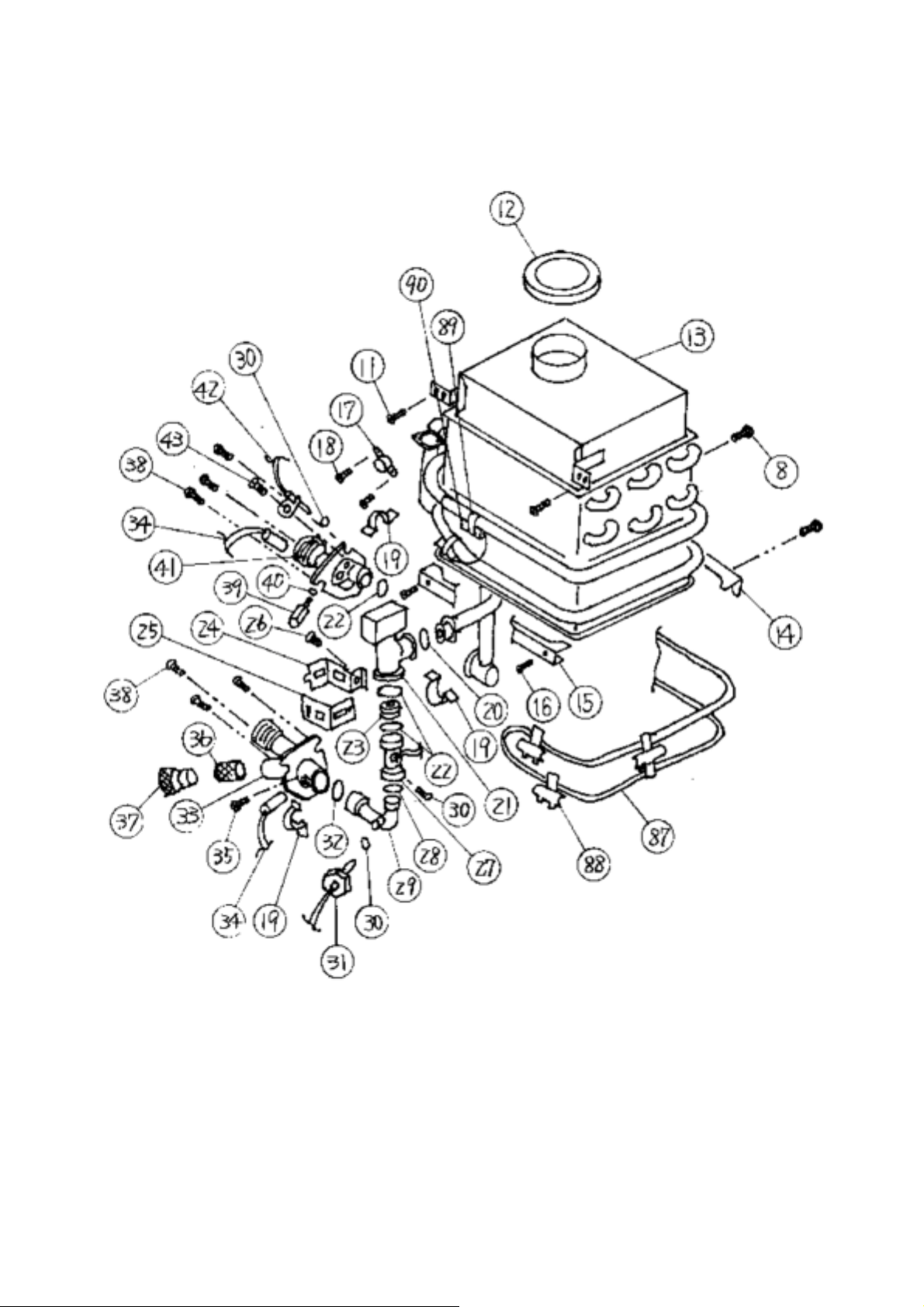
Water way assembly
Page 31

1 CASE ASSEMBLY 46 SCREW
2 BACK GUARD PANEL ASSEMBLY 47 SPARK ELECTRODE HOLDER
3 FRONT COVER 48 SPARK ELECTRODE
4 FIXING PLATE 49 FLAME SENSOR
5 TRANSFORMER 50 SCREW
6 JUNCTION BOX 51 DAMPER
7 JUNCTION BOX COVER 52 WIRE HOLDER
8 SCREW 53 SCREW
9 SCREW (COATED) 54 MANIFOLD
10 SCREW 55 GASKET
11 SCREW 56 GASKET
12 SILICON RING 57 GAS COUPLING
13 HEAT EXCHANGER ASSEM BLY 58 SCREW
14 HEAT EXCHNAGER FIXING PLATE (BACK) 59 O-RING
15 HEAT EXCHANGER FIXING PLATE (FRONT) 60 IGNITER
16 SCREW 61 SCREW
17 HI-LIMIT SWITCH 62 IGNITER
18 SCREW 63 GAS VALVE UNIT
19 QUICK RELEASE PLATE 64 O-RING
20 O-RING 65 SCREW
21 WATER CONTROL VALVE 66 GAS INLET FIXING P LATE
22 O-RING 67 GAS INLET
23 GASKET 68 FAN
24 QUICK RELEASE PLATE 69 SCREW
25 QUICK RELEASE PLATE 70 FAN DAMPER
26 SCREW 71 THERMOSTAT
27 FLOW SENSOR 72 SCREW
28 O-RING 73 SCREW
29 INLET CONNECTION PIPE 74 PRESSURE SWITCH
30 O-RING 75 SILICON TUBE
31 INLET THERMISTOR 76 PRESSURE SWITCH PORTPLATE
32 O-RING 77 PRESSURE SWITCH PORT
33 WATER INLET 78 POWER DISTRIBUTION PLATE
34 FREEZE PROTECTION HEATER 79 GROUND FAULT CIRCUI T INT ER RU PTER
35 SCREW 80 FUSE BOX
36 FILTER 82 COMPUTER FIX ING PL A TE
37 INLET DRAIN PLUG 83 COMPUTER BOARD
38 SCREW 84 REMOTE CONTROL CONNECTION
39 OUTLET DRAIN PLUG 85 COMPUTER TRANSFORMER
40 O-RING 86 SCREW
41 WATER OUTLET 87 OVERHEAT CUT-OFF FUSE
42 OUTLET THERMISTOR 88 OVERHEAT CUT-OFF FUSE FIXING PLATE
43 SC REW 89 FREEZE PROTECTION HEATER FIXI NG PLATE
44 COMBUSTION CHAMBER 90 FREEZE PROTECTION HEATER
45 BURNER ASSEMBLY
T - K2 PARTS LIST
Page 32
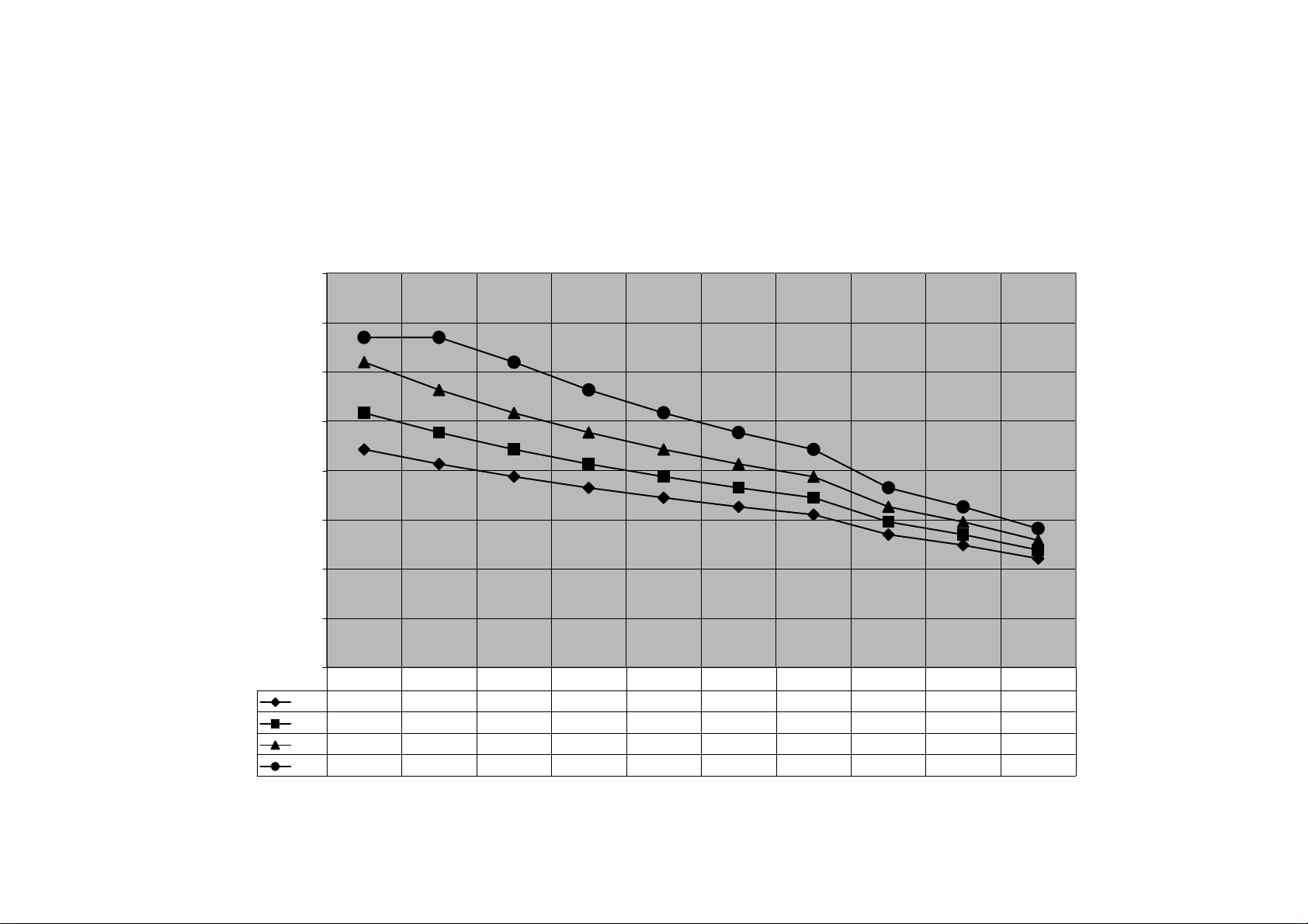
Flow Rate vs. Temperature
Hot Water Out GPM vs. Output Temperature for Various Input Temperature
8.0
7.0
6.0
5.0
4.0
Gallon per Minuite
3.0
2.0
1.0
0.0
40 F
50 F
60 F
70 F
110 115 120 125 130 135 140 155 165 180
4.44.13.93.63.43.33.12.72.52.2
5.24.84.44.13.93.63.43.02.72.4
6.25.65.24.84.44.13.93.33.02.6
6.76.76.25.65.24.84.43.63.32.8
Output Temperature
 Loading...