

WHIRLPOOL SPIW412LL/2 User Manual
Gebrauchsanweisung
Instructions for use
Mode d’emploi
Gebruiksaanwijzing
Istruzioni per l’uso
Brugsanvisning
Bruksanvisning
Käyttöohje
Manual de utilização
Instrucciones para el uso
Instrukcje użytkowania
Használati utasítás
ИнструкциЯза употреба
Қолдану бойынша нұсқаулық
Návod k použití
Návod na použitie
Instruc∑iuni de utilizare
Инструкции по эксплуатации
Інструкція з експлуатації


SPIW409LL/2, SPIW412LL/2, SPIW418LL/2, SPIW422LL/2
4578
9-:<*>?- ./%%%%%%0#2%3+
!#$&'(
ENGLISH Instructions for use Page 4
FRANÇAIS Mode d’emploi Page 30
РУCCКИЙ
Инcтpyкции по экcплyaтaции Cтpaницa
УКРАЇНСЬКА
4
Інструкція з експлуатації Сторінка
33
56
82

BEFORE USING THE APPLIANCE
Please ready all instructions carefully before using this product. When using this appliances, should always
follow this instruction to reduce the risk of fire, electric shock, and injury to person.
Please keep this manual. If you deliver the appliance to other users, do handover this manual together.
These instructions shall also be available on website: www.whirlpool.eu.
SAFETY PRECAUTIONS
• The Installation and service/repair
must be performed by a qualified
technician, in compliance with the
producer's instructions and
following local safety norms. Do
not repair or replace any parts of
the appliance unless it is
specifically written in the user
instructions.
• Do not pull the power supply
cord to remove it from the
socket. Do not twist or press the
power supply cord, and make
sure it is not broken.
• Do not touch the power plug,
circuit breaker and emergency
button when your hands are wet.
• Do not insert your fingers or
foreign substances into the air
inlet/outlet of indoor&outdoor
unit.
• Never block the air inlet or outlet
of indoor and outdoor unit.
• Physically or mentally disabled
people, children and people
without any experience with the
product are only allowed to use
the appliance if they have had
specific training on how to
operate the appliance by a person
responsible for their security and
well-being. The appliance is not
intended for use by disabled
without supervision.
• Children should be supervised to
ensure that they do not play with
the appliance (including remote
control).
• This appliance can be used by
children aged from 8 years and
above and persons with reduced
physical, sensory or mental
capabilities or lack of experience
and knowledge if they have been
given supervision or instruction
concerning use of the appliance in
a safe way and understand the
hazards involved. Children shall
not play with the appliance.
Cleaning and user maintenance
shall not be made by children
without supervision.
4
AIR CONDITIONER PRECAUTIONS
Please strictly follow the below
instructions:
• Long and direct exposure to cool
air might be harmful to health. It is
advisable to set the louvers in
order to avoid direct cool air and
deflect it within the room.
• Upon malfunctioning first turn the
appliance off by pressing the
ON/OFF button on the remote
control, then disconnect it from
power supply.
• Always turn off the air conditioner
by remote control first. Do not
use the power supply circuit
breaker or pull off the plug to turn
it off.
• Do not switch the appliance on
and off too often as this can
damage the appliance.
• Do not place any objects on the
outdoor unit.
• Disconnect the air conditioner
from the power supply if it is to
be left unused for a long period of
time or during a thunder/lightning
storm.
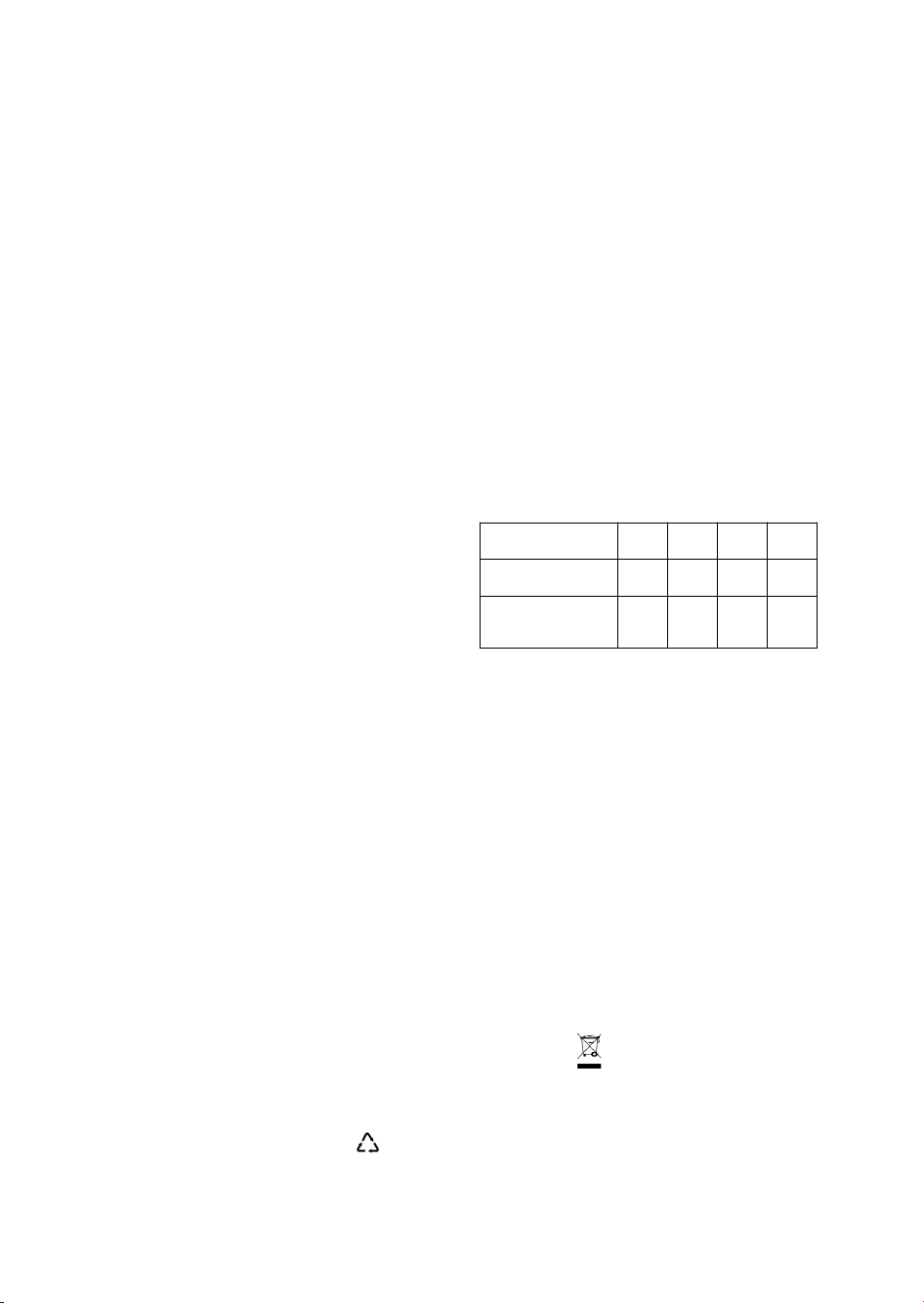
• This product contains Fluorinated
Greenhouse Gases covered by the
Kyoto Protocol, the refrigerant
gas being in a hermetically sealed
system. (R410a, GWP 2088)
Model 9K 12K 18K 22K
Gas weight (kg) 0.54 0.67 1.34 1.7
CO2 equivalent
(Ton)
1.128 1.400 2.800 3.550
SAFEGUARDING THE ENVIRONMENT
• This appliance has been made of recyclable or
re-usable material. Scrapping must be carried
out in compliance with local waste disposal
regulations. Before scrapping it, make sure to
cut off the mains cord so that the appliance
cannot be re-used.
• For more detailed information on handling and
recycling of this product, contact your local
authorities who deal with the separate collection
of rubbish or the shop where you bought the
appliance.
SCRAPPING OF PACKAGING
• The packaging can be 100% recycled as
confirmed by the recycling symbol . The
various parts of the packaging must not be
dispersed in the environment, but must be
scrapped in line with local authority regulations.
SCRAPPING OF APPLIANCE
• This appliance is marked according to the
European Directive 2002/96/EC, Waste
Electrical and Electronic Equipment (WEEE).
• By ensuring that this product is disposed of
correctly, you will help to prevent potentially
negative consequences for the environment and
for human health.
• The symbol on the product or on the
documents accompanying the product indicates
that this appliance should not be treated as
household waste, but must be given to the
appropriate local gathering place where electric
and electronic appliances are stored and
recycled.
5
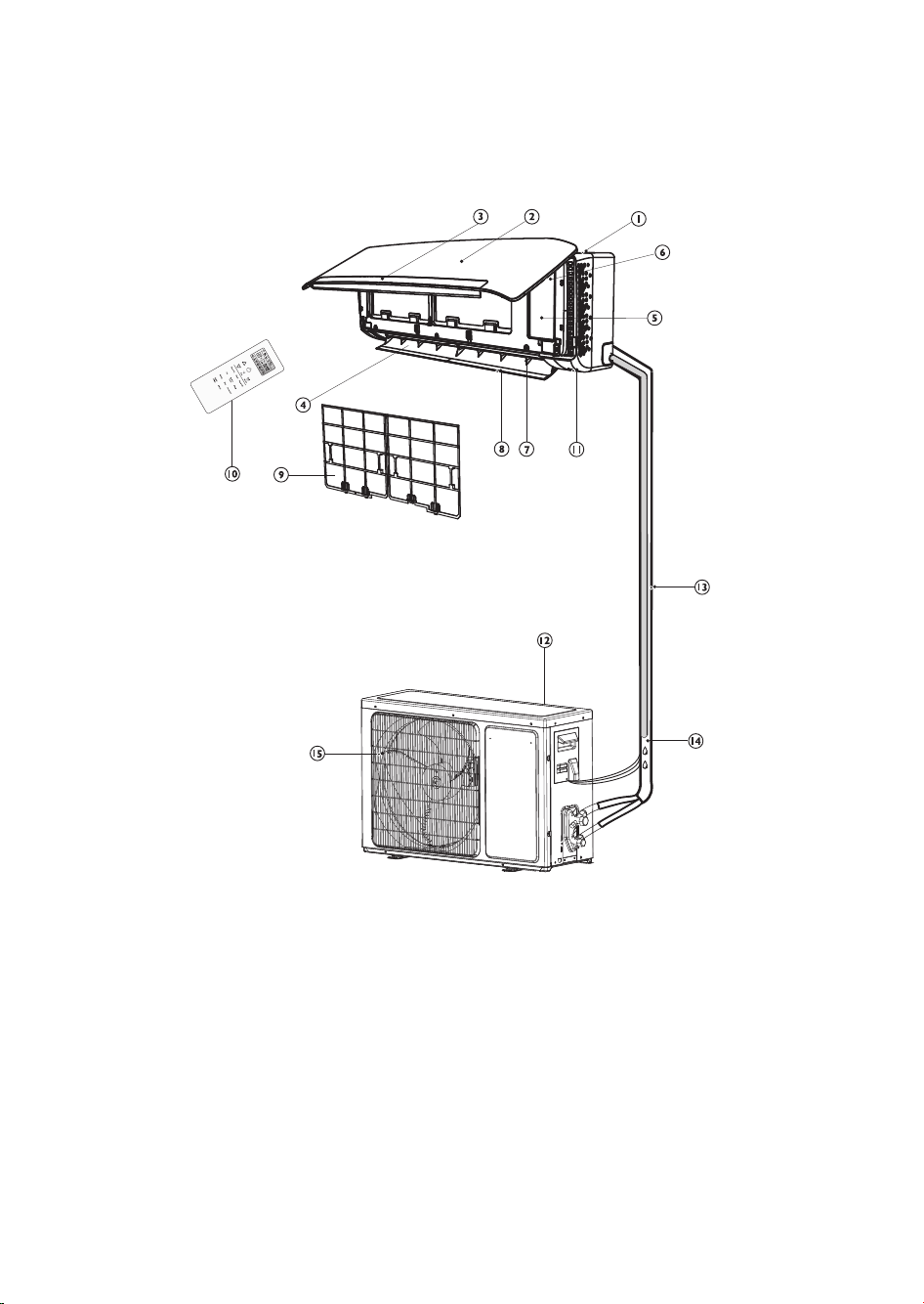
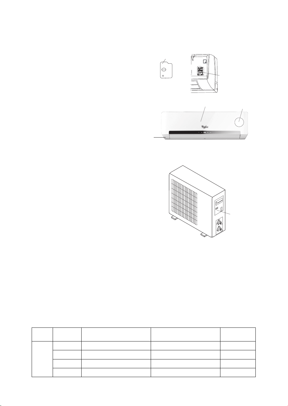
PRODUCT DESCRIPTION
Indoor unit
Outdoor unit
Indoor unit
1. Air Intake
2. Front Panel
3. Display panel
4. Air Outlet
5. Electrical box
6. Filter reset button
7. Vertical Adjustment Louver
8. Horizontal Adjustment Louver
9. Air Filter
10. Remote Control
11. On-off Switch
Images in the user instructions are based on external views of standard models, shape and design vary
according to the model.
Outdoor unit
12. Air Intake
13 Pipes and Power Connection Cord
14. Drain Hose
Note: Condensate water drains at COOLING
or DRY operation.
15. Air Outlet
6
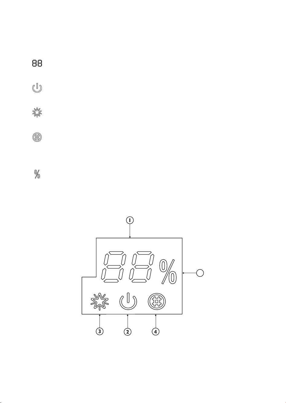
CONTROL PANEL DISPLAY INDICATORS
DESCRIPTION
Temperature indicator (1)
Displays set temperature.
It shows "FC" as a reminder to clean the filter.
Running indicator (2)
It lights up during operation.
It flashes during outside unit defrosting.
6th Sence indicator (3)
It lights up when 6th sense is on.
It goes off when 6th sense ends.
Filter monitor indicator (4)
It flashes when the filter needs to be cleaned.
Filter monitor indicator flashes after 720 hours of usage as reminder to clean the filter.
After filter cleaning, press the filter reset button located on the indoor unit behind the front panel
in order to interrupt the flashing of the filter monitor indicator.
Humidity indicator (5)
It lights up when showing the humility level.
It goes off when showing the temperature.
5
7
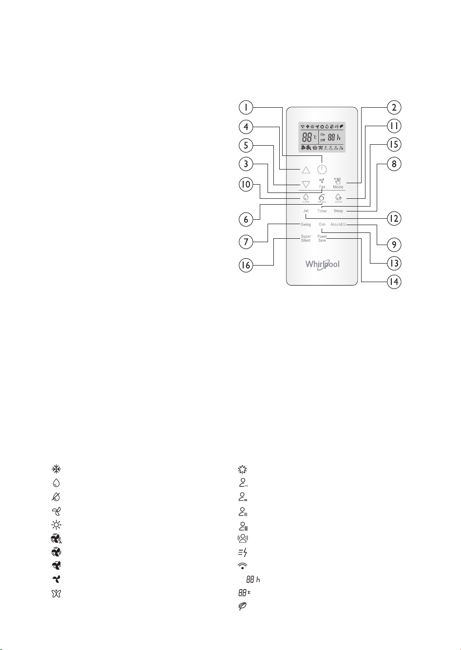
REMOTE CONTROL FUNCTIONS
O
ON
N
O
OF
FF
F
AND INDICATORS
1. ON/OFF BUTTON
Starts and/or Stops the appliance by pressing
this button.
2. MODE BUTTON
Used to select the operation mode.
3. FAN BUTTON
Used to select fan speed in sequence auto,
high, medium or low.
4-5. TEMPERATURE BUTTON
Used to select the room temperature. Used
to set time in timer mode and real time clock.
6. 6th SENSE BUTTON
Sets or cancels 6th sense operation.
7. SWING BUTTON
Stops or starts horizontal adjustment louver
swinging and sets the desired up/down airflow
direction.
8. SLEEP BUTTON
Sets or cancels Sleep Mode operation.
9. AROUND U BUTTON
Used to set or cancel Around U function.
10-11. HUMIDITY BUTTON
Used to set desired humidity level, they are
only available under 6th SENSE mode.
13. JET BUTTON
Used to start or stop the fast cooling or
heating.
13. DIM BUTTON
Used to turn on or turn off display light on
indoor unit.
14. POWER SAVE BUTTON
Used to start or stop the power save
operation.
15. TIMER BUTTON
Used to set the timer.
16. SUPER SILENT BUTTON
Used to start or stop the super silent
operation.
INDICATOR SYMBOLS ON RC DISPLAY
Cooling indicator
Humidity plus indicator
Humidity minus indicator
Fan only indicator
Heating indicator
Auto fan speed
High fan speed
Medium fan speed
Low fan speed
Super silent indicator
6th SENSE indicator
Sleep indicator 1
Sleep indicator 2
Sleep indicator 3
Sleep indicator 4
Around U indicator
Jet indicator
Signal transmission
Display set timer
Display set temperature
Power save indicator
8
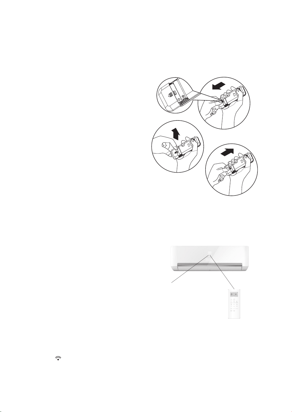
STORAGE AND TIPS FOR USING THE
REMOTE CONTROL
How to insert the batteries
1. Insert a pin and gently press down on the
battery cover and push in the direction of the
arrow to remove, as shown.
2. Insert 2 AAA batteries (1.5V) into the
compartment.
Ensure that "+" and "-" polarity is correctly
positioned.
3. Close the battery cover on the remote control.
How to remove the batteries
Remove the battery cover in the direction of the
arrow.
Press the positive pole of the battery softly with
your fingers, then draw the batteries out of the
compartment. All this should be done by adults,
children are forbidden to remove the batteries
from the remote control in order to avoid danger
of swallow.
Disposal of the batteries
To protect natural resources and to promote
material reuse, please separate batteries from
other types of waste and recycle them through
your local, free battery return system.
Precautions
• When replacing the batteries, do not use new
batteries with old batteries, or different types of
batteries as this may cause the remote control
to malfunction.
• If you do not expect to use the remote control
for some time, take the batteries out to prevent
leakage of battery acid in the remote control.
• Operate the remote control within effective
range. Keep the remote control at least 1 meter
from any TV set or HI-FI equipment.
• If the remote control does not work normally,
take the batteries out and reinstall after 30
seconds. If it still does not work install new
batteries.
• To operate the appliance by remote control,
point the remote control at the receiving device
on the indoor unit, to ensure receiving
sensibility.
• To send a message from remote control, the
symbol will flash for 1 second. On receipt
of the message, the appliance will emit a beep.
Signal receptor
• The remote control will operate the air
conditioner at a distance of up to 7m.
• Each time the batteries are replaced in the
remote control, the remote control is pre-set at
Heat Pump mode.
9
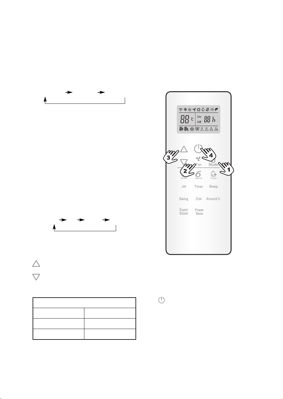
OPERATING MODE DESCRIPTION
Operation Modes:
1. Selecting mode
Each time MODE button is pressed, the operation
mode is changed in sequence:
COOLING FAN ONLY HEATING
Heating mode is not available for cooling only air
conditioners.
COOLING mode: used to cool your room to feel
cool and comfort in the hot season.
DRY mode: used to remove moisture to feel
comfort in a humid climate.
FAN ONLY mode: used to ventilate your room,
the air conditioner operates like a fan.
HEATING mode: used to heat your room to feel
warm in the cold season.
Note:In order to prevent cool air blowing, 2-5
minutes are necessary to preheat the indoor unit
at HEATING operation start. The indoor fan will
not work during preheating.
2. Setting fan speed
Each time the "FAN" button is pressed, the fan
speed is changed in sequence:
Auto High Medium Low
At "FAN ONLY" mode, only "High","Medium" and
"Low" are available.
3. Setting temperature
Press once to raise temperature setting by 1
raise °C
Press once to lower temperature setting by 1
lower °C
Press these two button and hold consistently,
you can change the number quickly.
Range of available set temperature
*HEATING, COOLING 16°C~30°C
DRY NA
FAN ONLY unable to set
*Note: Heating mode is NOT available for
cooling only models.
4. Turning on
Press button, when the appliance receives the
signal, the RUNNING indicator of the indoor unit
lights up.
During mode changes wait a few seconds and
repeat the operation if the unit does not respond
at once.
When selection the heating operation, air flow will
start after 2-5 minutes.
10
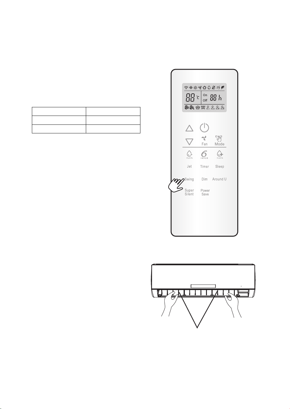
AIRFLOW DIRECTION CONTROL
5. Airflow direction control
Horizontal airflow is automatically adjusted to a
certain angle in accordance with the operation
mode after turning on the unit.
The direction of airflow can be also adjusted to
your own requirement by pressing the "SWING"
button of the remote control.
Operation mode Direction of airflow
COOLING, DRY horizontal
*HEATING, FAN ONLY downward
*Heating mode is only available for heat pump
models.
Horizontal airflow control (using the remote
control)
Use the remote control to set the flow angles.
Swinging airflow
Pressing "SWING" button once, the horizontal
adjustment louver will swing up and down
automatically.
Desired direction airflow
Pressing the "SWING" button again to hold the
horizontal adjustment louver when the louvers
swing to a suitable angle as desired.
Vertical airflow control (by hands)
Turn the control rods of the vertical adjustment
louvers to change vertical air flow as shown.
Note: The shape of the unit may look different
from that of the air conditioner you have selected.
A - Do not turn the horizontal adjustment louvers
manually, otherwise malfunction may occur. If
that happens, turn off the unit first and cut off
the power supply, then restore power supply
again.
B - It is better not to let the horizontal adjustment
louver tilt downward for a long time at
COOLING or DRY mode to prevent
condensed water from dripping.
control rod of vertical
adjustment louvers
11

MODE AND FUNCTION DESCRIPTIONS
6th SENSE MODE
The sensor in the indoor unit, which measures temperature and humidity in the room, keeps the room
temperature in the most comfortable level by controlling the temperature and the fan speed automatically.
Press the 6th SENSE button on the remote controller to enable it:
6th SENSE icon appears automatically on the remote control display, in cooling mode the air conditioner
will set the fan speed to auto, adjust the temperature and humidity automatically according to the
enviroment.
1. The unit will automatically sense the outdoor air tempearture every 3 hours and select the
operation mode for you, detail see below table.
Outdoor temperature range Mode setting
25°C ≤Tod
22°C ≤Tod < 25°C
22°C < Tod HEATING
Tod is= outdoor enviroment temeprature.
Note: Mode cannot be switched manually under 6th SENSE function.
2. In cooling mode, unit will automatically set a comfortable temperature and humidity for you,
you can adjust it base on your need, to adjust temperature by pressing the and button
on remote control. On the display , "0" to indicate the default, other number (-3, -2, -1, 0, 1, 2, 3)
corresponding to tempearture change as below:
Outdoor temperature range Default mode Default setting Max Min
30°C ≤Tod
25°C ≤Tod < 30°C
22°C < Tod HEATING 22°C 25°C 19°C
3. After setting the desired temperature, there will be a new humidity setting display. You can
press the and to change the setting, the range is from -15% to 15% based on the
default setting.
COOLING
FAN ONLY
COOLING 22°C 25°C 19°C
COOLING 21°C 24°C 18°C
12
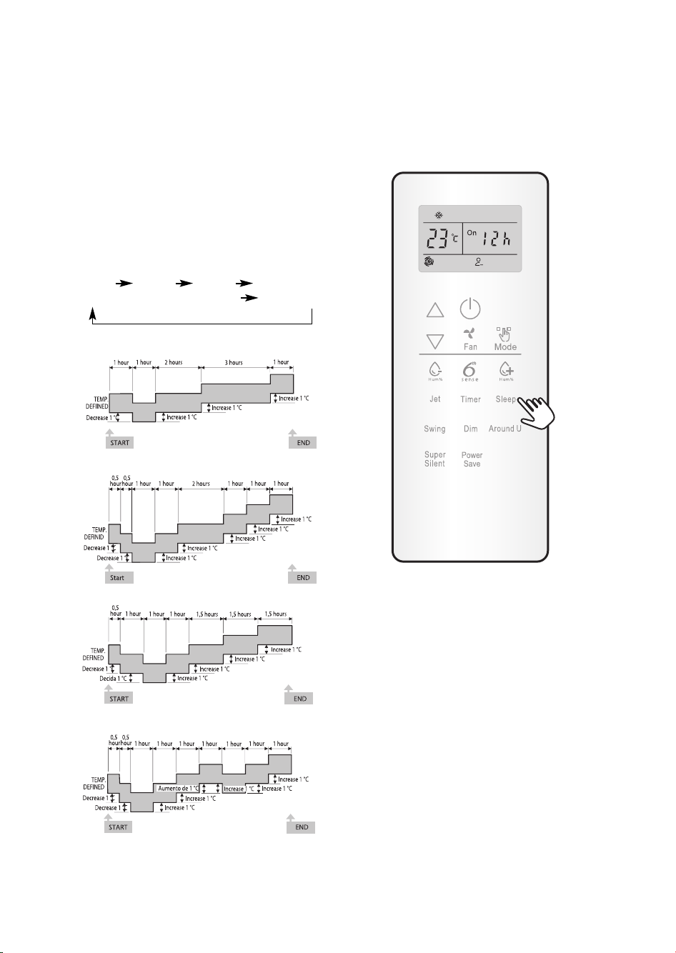
SLEEP mode
SLEEP mode can be set in COOLING,
HEATING or DRY operation mode.
This function gives you a more comfortable
environment with low nois level for sleep.
The appliance will turn off automatically after
operating for 8 hours.
Fan speed is automatically set at low speed.
For 9K/12K models only.
Each time SLEEP button is pressed, the operation
mode is changed in sequency:
SLEEP 1 SLEEP 2 SLEEP 3
SLEEP 4 ESCAPE SLEEP
SLEEP for Children (mode 1):
SLEEP for Teenagers (mode 2):
SLEEP for Adults (mode 3)
SLEEP for Elderly (mode 4):
*Note:
Heating is NOT available for cooling only air
conditioner.
Once sleep mode is set, "Running" indicator will
flash for 10 times, then the whole display will light
off.
13
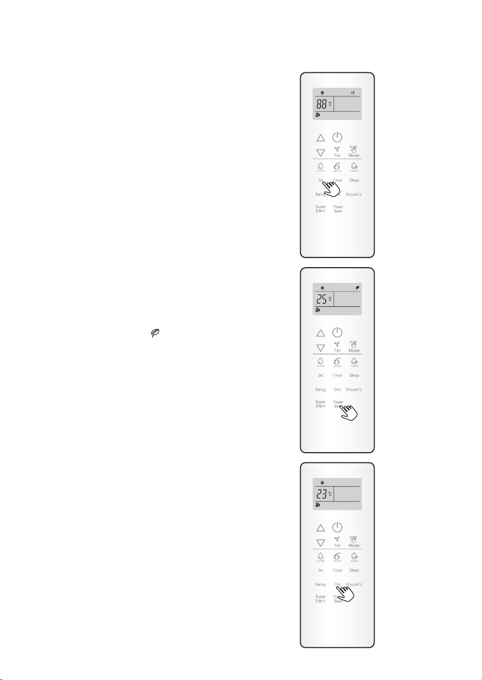
JET mode
• JET mode is used to start or stop fast cooling or
Heating.
Fast cooling operates at high fan speed, and set
temperature automatically to 16°C.
Fast heating operates at auto fan speed,changing
set temperature automatically to 30 °C.
• In JET mode, you can set airflow direction or
timer. If you want to quit from JET mode, press
any - JET , MODE, FAN, ON/OFF, SLEEP or
TEMPERATURE SETTING button, the display
will return to the original mode.
Note:
• SLEEP and 6th SENSE buttons are not available in JET
mode.
• The appliance will continue working in JET mode
if you don't quit from it by pressing any of the
buttons mentioned.
POWER SAVE function
POWER SAVE mode can be available in
COOLING, HEATING, DRY and FAN ONLY
operation mode.
When pressing this button, will display on
remote control.
POWER SAVE function under COOLING,
HEATING and DRY mode, the appliance will set
the temperature at 25°C with low fan speed.
POWER SAVE function under FAN ONLY mode:
the appliance will set at low fan speed.
Change mode or press the power save button
again to cancel this function.
Note: Fan speed and temperature can not be
adjusted under this mode.
DIM function
Press this button to turn on or turn off display light
on indoor unit control panel.
Press once to turn off the indoor unit display light,
press again or press any other buttons to turn it
on.
If you press the other buttons when the indoor
unit display light is off, press once to turn on the
light, press the second time for activating the
function.
14
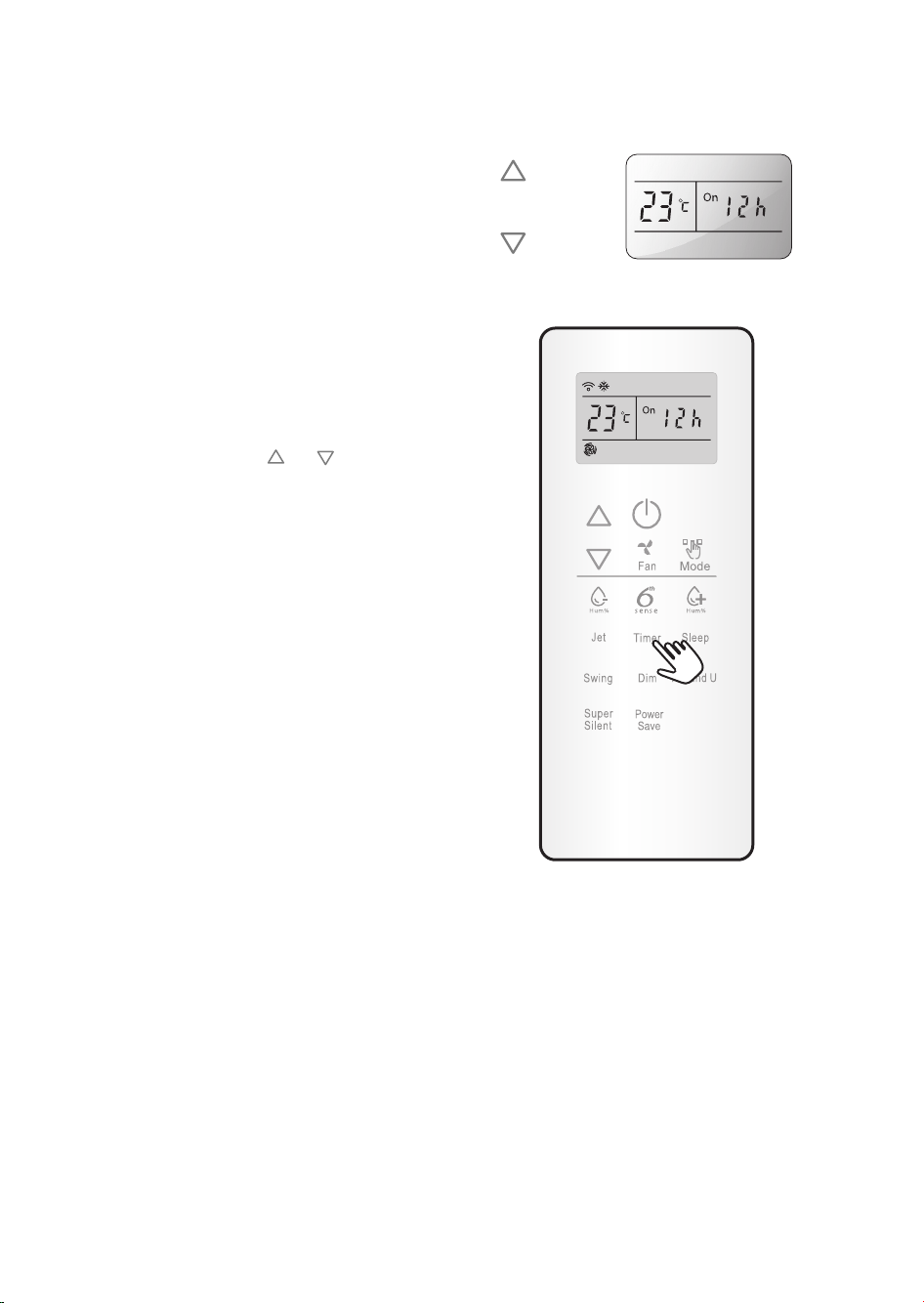
TIMER function
It's convenient to set the timer on with TIMER
button before you leave so that you will come back
to the comfortable room temperature you set.
Press the TIMER button to set a switch-on button
when the appliance is off. Press the TIMER button
to set a switch-off timer during operation.
How to set TIMER
1. Set desired operating mode, temperature setting
and fan speed firstly, then press the TIMER
button and "01h" flashed on LCD.
2. Set desired operating mode, temperature setting
and fan speed firstly, then press the TIMER
button and "01h" flashed on LCD.
3. Point the remote control at the signal receptor
or
of the unit, press the
"01h" flashes.
Choose the timer you want, then press the
TIMER button.
• A "beep" can be heard.
• Timer indicator on the control panel lights up.
• "h" stops flashing.
4. To cancel the set timer: press the TIMER button
again, a "beep" can be heard.
NOTES:
• The range can be set is 1 hour to 24 hours.
• After setting a switch-on timer when the
appliance is off, the Timer light on the control
panel lights and
• Setting a switch-off timer when the unit working,
the Timer light of the control panel lights up.
button when
Increase
Decrease
15
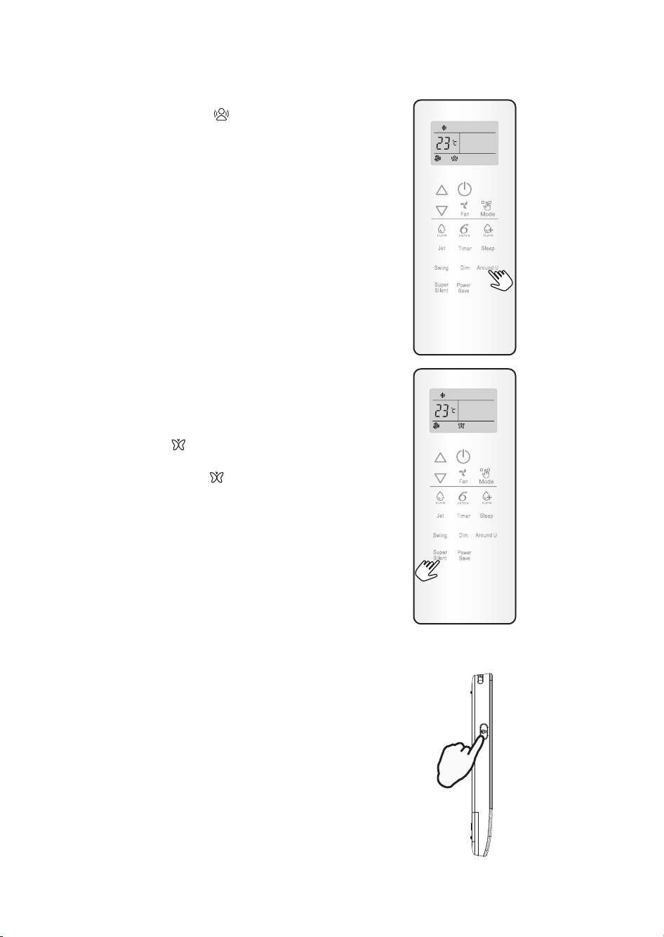
Around U function
When you press this button, will display,
remote control transmits the actual room
temperature around it to the indoor unit, and the
appliance will operate according to this
temperature to let you feel more comfortable.
Please keep the remote control in a location where
it can transmit the signal to the indoor unit
properly.
Press once to set and press again to cancel.
Room temperature will be displayed on remote
controller screen once this function is set.
When you change the temperature setting, set
temperature will be displayed for 5s, then it
switches to display room temperature.
SUPER SILENT function
Press SUPER SILENT button to let the unit operate
at low noise level to get a quiet and comfortable
room environment. will display on remote
control.
Note: Super silent function will be off when
pressing MODE button, or pressing SUPER
SILENT button or pressing FAN button again.
This function may not be available on some
models.
UNLOCK button
The unlock button at left side of remote controller
is used to turn on or turn off the backlight and
button PRESS functions.
Press this button, the backligh will be lighted up
and function buttons will be activated for use. Press
again to lock the remote controller.
If no operation on remote controller for 10s, the
remote controller will be locked automatically.
16
PRESS
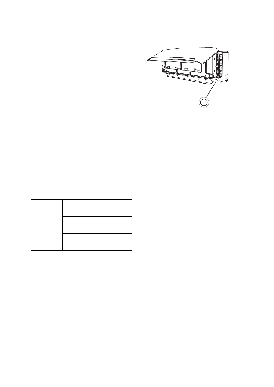
EMERGENCY OPERATION
Under emergency situation or when remote control
is missing, you can control the unit by pressing the
on/off swith located on the indoor unit.
• Turn on the appliance: when the unit is off, press
this button, it will start up and operate in 6th
SENSE mode.
• Turn off the appliance: when the unit is on, press
this button, the unit will stop working.
Note: Do not press this button for a long time
as it will cause malfunction.
Auto-Restart Function
If you want to set auto-restart, switch on the power supply, press the ON/OFF button on the indoor unit
and hold for over 5 seconds, auto-restart is set with buzz sound.
If the auto-restart has been set, press the ON/OFF button on the indoor unit and hold for over 5 seconds,
auto-restart function will be cancelled with a buzz sound and air conditioner is on standby mode.
on/off switch
PROTECTION
Operating condition
The protective device maybe trip and stop the
appliance in the cases listed below.
Outdoor air temperature is over 24°C
Heating
Cooling
Dehumidifying Room temperature is below 18°C
If the air conditioner runs in COOLING or DRY
mode with door or window opened for a long
time when relative humidity is above 80%, dew
may drip down from the outlet.
Features of protection device
Wait at least 3 minutes before restarting the unit
after operation stops or changing mode during
operation. After connecting to power supply and
turning on the appliance immediately, a delay of 20
seconds may occur before it starts to operate. If all
operation has stopped, press ON/OFF button
again to restart. Timer should be set again if it has
been cancelled.
Outdoor air temperature is below -7°C
Room temperature is over 27°C
Outdoor air temperature is over 43°C
Room temperature is below 21°C
Features of COOLING mode
Anti-freezing
When the temperature of the indoor heat
exchanger drops to 0° or below, compressor will
stop working to protect the appliance.
Features of HEATING mode
Preheating
In order to prevent cool air blowing, 2-5 minutes
are necessary to preheat the indoor unit at
HEATING operation start. The indoor fan will not
work during preheating.
Defrosting
In HEATING operation the appliance will defrost
(de-ice) automatically to raise efficiency. This
procedure usually lasts 6-10 minutes. During
defrosting, fan stops running and running indicator
flashes.
After defrosting is completeed, it returns to
HEATING mode automatically.
17
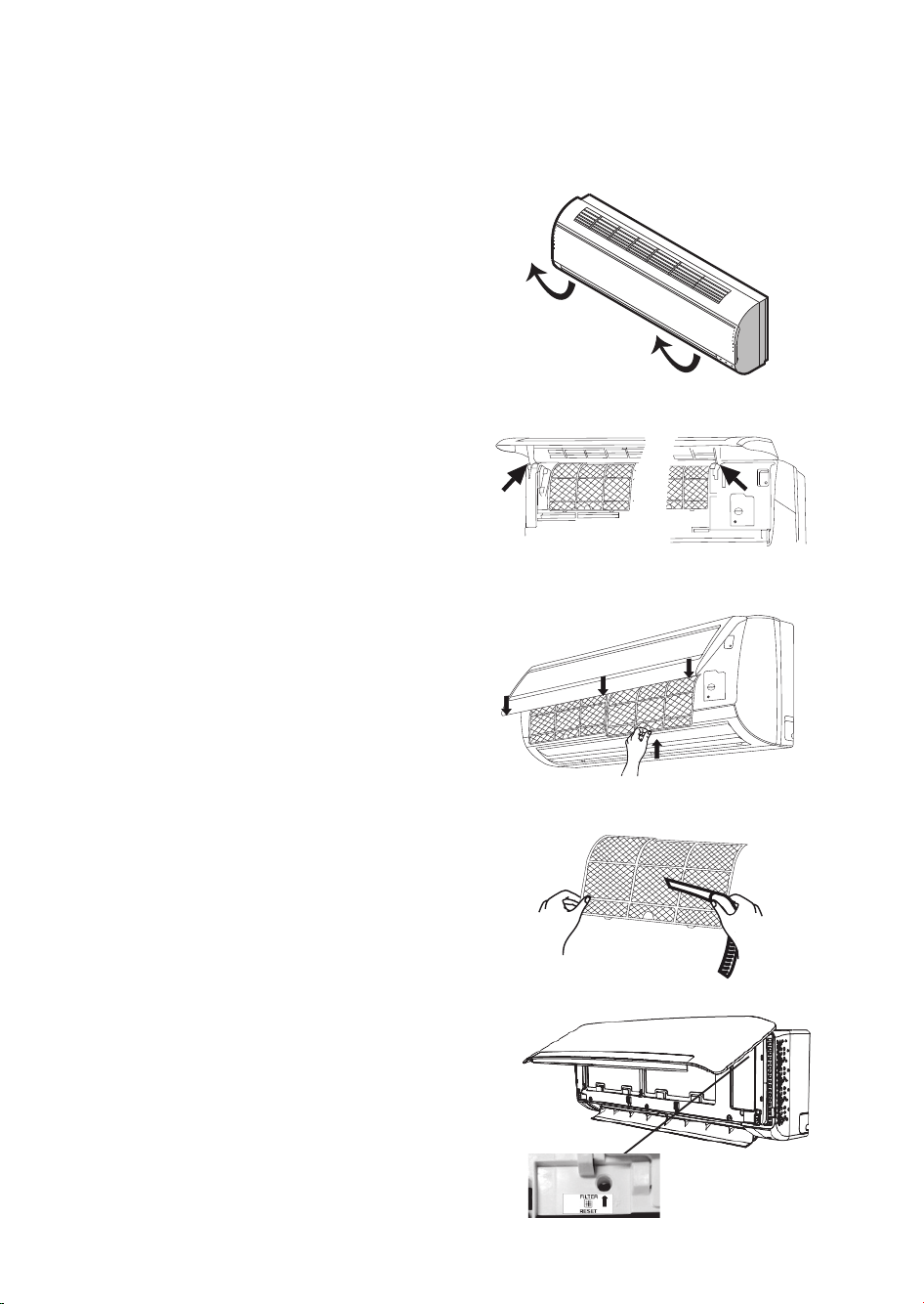
MAINTENANCE
Clean front panel of Indoor Unit
1. Disconnect from the power supply
Turn off the appliance first before disconnecting
from power supply.
2. Remove the front panel
Open the front panel as shown by the arrow
(Fig. A).
Pull the slots at the side of the front panel with
force to take out the front panel (Fig. B).
3. Clean the front panel
Wipe it with a soft and dry cloth. Use lukewarm
water (below 40°C) to clean if the appliance is
very dirty. After cleaning let it dry.
4. Refit and close the front panel.
Refit and close the front panel by pushing it
downward.
Note:
• Do not use substances such as gasoline or
polishing powder to clean the appliance.
• Do not sprinkle water onto the indoor unit
Dangerous! Electric shock!
Clean Air filter
It is necessary to clean the air filter after using it
ffor about 200 hours.Clean the air filter every two
weeks if the air conditioner operates in an
extremely dusty environment.
1. Disconnect from the power supply
Turn off the appliance first before disconnecting
from power supply.
2. Take out air filter (Fig. C).
1. Open the front panel.
2. Press the handle of the filter gently.
3. Slide out the filter.
3. Cleaning the air filter (Fig. D).
If the filter is very dirty, clean it with a solution
of lukewarm water and neutral detergent.
After cleaning let it dry.
4. Refit the filter, press the filter reset button
(Fig.E) at right side by using a cylinder pin
and close the front panel.
Note:
• To avoid injury, do not touch the fins of
indoor unit with your fingers after
removing the filter.
• Do not attempt to clean the inside of the
air conditioner by yourself.
• Do not clean the filter in washing machine.
Fig. A
Fig. B
Fig. C
Fig. D
Filter Reset button
18
Fig. E
TROUBLESHOOTING
Operation problems are often due to minor causes, please check and refer to the
following chart before contacting the service. This may save time and unnecessary
expenses.
Trouble Analysis
• Is the protection device or fuse blown?
Does not run
No cooling or
heating air
Ineffective control
Does not operate
immediately
Peculiar smell
A sound of running
water
Cracking sound
Mist sprays from
the outlet
Running indicator
flashes but indoor
fan stops.
• Please wait for 3 minutes and start again, protection device may be preventing
unit to work.
• Are the remote control batteries low?
• Is the plug not properly plugged?
• Is the air filter dirty?
• Are the intakes and outlets of the air conditioner blocked?
• Is the temperature set properly?
• Are doors or windows open?
• Has there been a strong interference (from excessive static electricity discharge,
power supply voltage abnormality)? Note that operation will be abnormal, in this
case unplug from the power supply and re-plug after 2-3 seconds.
• 3 minute delay will occur when changing mode during operation.
• This smell may come from another source such as furniture, cigarette etc, which
is sucked in the unit and blown out with the air.
• Normal behaviour caused by the flow of refrigerant in the air conditioner.
• Defrosting sound in heating mode.
• The sound may be generated by the expansion or contraction of the front panel
due to temperature changes.
• Mist is present in the room with low temperature? Normal behaviour due to
cool air discharged from indoor unit during COOLING or DRY operation
mode.
• The unit is shifting from heating mode to defrost. The indicator will light off and
return to heating mode.
Note: If the problems still have, turn off the appliance and disconnect from power supply,
then contact the nearest Whirlpool Authorized Service Center. Do not attempt to move,
repair, disassemble, or modify the appliance by yourself.
19
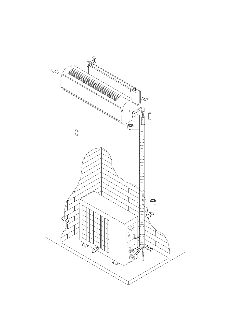
INSTALLATION INSTRUCTIONS
Installation diagram
Distance from ceiling
Distance from wall
should be over 50mm
Indoor unit
Distance from floor
should be over 2500mm
should be over 200mm
Distance from the wall
should be over 50mm
Outdoor unit
Air intake distance from
Air intake distance from
the wall should be over
250mm
Air outlet distance from the wall
should be over 500mm
the wall should be over
250mm
Over 250mm
NOTE: The figure above is only a simple presentation of the unit, it may not match the external
appearance of the product you purchased. Installation must be performed in accordance with the national
wiring standards by authorized service people only.
20

INSTALLATION SERVICE
Before installation
1. Please read this manual carefully
5. Mount with the lowest moving
before installation.
2. The appliance must be installed
according to national wiring rules
6. After installing, the consumer
and according to this manual by
qualified technicians.
3. Any change of installation
position must be handled by
professionals;
4. Check the product to verify that
it has not been damaged before
installation.
SAFETY PRECAUTION
parts of indoor unit at least 2.5m
above floor or grade Level.
must operate the appliance
correctly according to this
manual, keep a suitable storage
for maintenance and move of it
in the future.
1. The power supply must be of
rated voltage with special
circuitry for the appliance. The
normal operating range of
voltage is 90%~110% of rated
voltage. The diameter of the
power cord must comply with
requirements.
2. The user power supply shall
have a reliable grounding
terminal. It is prohibited to
connect the grounding wire to
the following items:
1) Water Supply Pipe
2) Gas Pipe
3) Sewage Pipe
4) Other positions that are
considered unsafe.
3. Ensure safe grounding and a
grounding wire connected with
the special grounding system of
the building, installed by
professionals. The appliance
must be fitted with electrical
leakage protection switch and an
auxiliary circuit breaker with
sufficient capacity. The circuit
breaker must also have a
magnetic and a thermal tripping
function to ensure protection in
case of short-circuit and
overload.
Type Model
Split Inverter
9/12K 16A
18/24K 20A
Required Capacity
of air break switch
21

SAFETY PRECAUTION
4. Make sure that the power supply
cord is long enough to allow the
right connection. Do not use any
extension cord for power supply.
5. If the supply cord is damaged, it
must be replaced by the
manufacturer or its service agent
or a similarly qualified person in
order to avoid a hazard;
6. An all-pole disconnection switch
having a contact separation of at
least 3mm in all poles should be
connected in fixed wiring.
7. Risk of electric shock can cause
injury or death: Disconnect all
electric power supplies before
servicing.
8. The connection of power cord
and the cable connection
between indoor unit and
outdoor unit shall be in
accordance with the wiring
diagram attached on the
appliance.
9. Once installation is completed,
the electric components must
not be accessible to the users.
10. Use two or more people to
move and install the appliance to
avoid excessive weight hazard.
11. After unpacking the air
conditioner, keep all packaging
materials well out of the reach of
must also have a magnetic and a
thermal children.
12. According to the character of
refrigerant the pressure of the
tube is very high, so be sure to
careful when you install and
repair the appliance.
13. A residual current device(RCD)
having rated residual operation
current not exceeding 30mA
shall be incorporated in fixed
wiring according to national law.
22
Select the best location
Location for Installing Indoor Unit
• Where there is no obstacle near the air outlet
and air can be easily blown to every corner of
room.
• Where piping and wall hole can be easily
arranged.
• Observe the required distance from ceiling and
wall according to the installation diagram.
• Where the air filter can easily be removed.
• Keep the unit and remote control 1m or more
from television, radio etc.
• To prevent the effects of a fluorescent lamp,
keep the unit as far as possible from it.
• Do not put anything near the air inlet that could
obstruct it.
• In a place that can bear the weight and will not
increase operating noise and vibrations.
• The indoor unit is not suitable to be installed in
areas used for laundry.
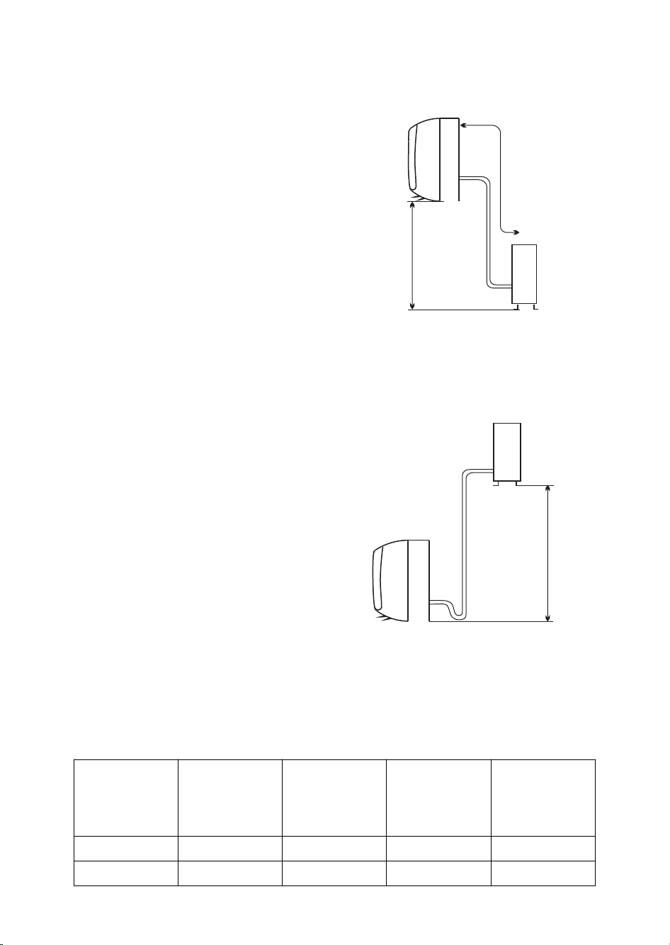
Indoor unit
Pipe length is
3~15 meters
Outdoor unit
Height should
be less than 5m
Location for Installing Outdoor Unit
• Install in a convenient and well-ventilated place.
• Avoid installing it where flammable gas could
leak.
• Observe the required distance from the wall
Pipe length is
3~15 meters
Outdoor unit
according to the installation diagram.
• The distance between Indoor and outdoor unit
should be 3 meters and can go up to maximum
15 meters with additional refrigerant charge.
• Do not install the outdoor unit in a dirty or
greasy place, near a vulcanization gas exit.
• Avoid installing it at the roadside where it could
be soiled with muddy water.
• A fixed base where operating noise will not
increase.
• Where the air outlet is not obstructed.
• The installation position shall be able to
Indoor unit
withstand the weight and vibration of the
outdoor unit and ensure safe installation;
• Where drained water does not become any
problem.
• Install the outdoor unit at a place where the air
discharged and the operation noise would not
disturb your neighbours.
Model
Standard tubing
Length (m)
Limit of Tubing
Length (m)
Limit of Elevation
Difference H (m)
9K/12K/18K 5 15 5 20
Height should be less
than 5m
Required extra
refrigerant when
the connecting
tube over 5m
(g/m)
24K 5 15 5 30
23

INDOOR UNIT INSTALLATION
1. Installing the Mounting Plate
• Select a location to install the mounting plate
according to the indoor unit location and piping
direction.
• Adjust the mounting plate horizontally with a
gradienter or plumb line.
• Drill holes 32mm in deep on the wall.
• Insert the plastic plugs in the hole, then fix the
mounting plate with tapping screws.
• Check that the mounting plate is well fixed.
NOTE: The shape of your mounting plate may be different from the one above, but installation method is
similar.
2. Drill a Hole for Piping
• Decide the position of the hole for piping
according to the location of mounting plate.
• Drill a hole with diameter around 70mm on the
wall. The hole should slightly be inclined
downward toward outside.
• Install a sleeve through the wall hole to keep the
wall tidy and clean.
3. Indoor Unit Piping Installation
• Fit the piping (liquid and gas pipe) and cables
through the wall hole from outside or fit them
from inside after completing indoor piping and
cables connections so as to connect to outdoor
unit.
• Decide whether saw off the plastic part in accordance with the piping direction (as shown below).
Indoor
Outdoor
Wall hole sleeve
(hard polythene tube
prepared by user)
Mounting plate
5mm
(downward
inclination)
Piping direction
trough
Unloading
piece
4
1
Saw the unloading piece off
along the trough
3
2
NOTE:
When fixing the pipe along directions 1, 2 or 4, saw the corresponding plastic part off the indoor unit base.
• After connecting the piping as required, install the drain hose. Then connect the power connecting
cable. After connecting, wrap the piping, cable and drain hose together with thermal insulating
materials.
NOTE: Do not connect to power supply during installation.
24
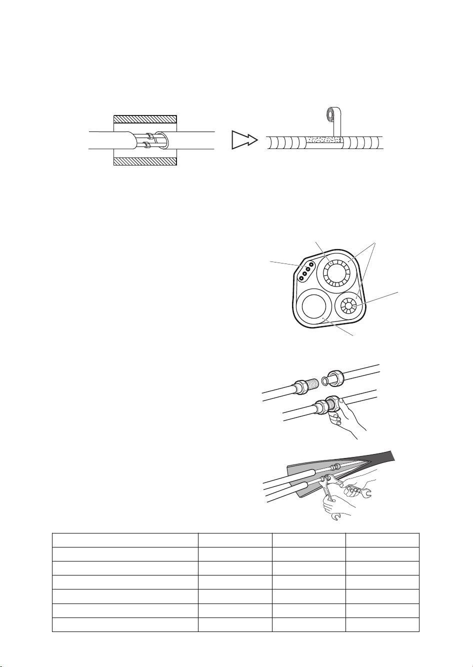
IMPORTANT:
Piping Joints Thermal Insulation:
Wrap the piping joints with thermal insulating materials and then wrap with a vinyl tape.
Wrapped with vinyl type
Thermal insulation
Thermal Insulation piping:
a. Place the drain hose under the piping.
b. Insulation material: polythene foam over 6mm in thickness.
NOTE: Drain hose is prepared by user.
• Drain hose should point downward for easy drain
flow. Do not twist the drain pipe, leave it sticking
out or waving around, do not immerse the end in
water. If an extension drain hose is connected to the
drain pipe, make sure to be thermally insulated
when passing it through the indoor unit.
• When the piping is directed to the right, piping,
power cable and drain hose should be thermally
insulated and fixed at the rear of the unit.
Piping Connection:
a. Connect indoor unit pipes with two wrenches. Pay
special attention to the torque allowed as shown
below to prevent the pipes, connectors and flare
nuts from being deformed and damaged.
b. At first fingers-tighten them, then use the wrenches.
Note: do not cut the piping if the connection pipe is
over requirement.
Power connecting
cable
Large pipe
Thermally
insulated tube
Small pipe
Drain hose
(prepared by user)
Pipe size Torque Nut width Min. thickness
Liquid Side (1/4 inch) 15~20N.m 17mm 0.5mm
Liquid Side (3/8 inch) 30~35N.m 22mm 0.6mm
Gas Side (3/8 inch) 30~35N.m 22mm 0.6mm
Gas Side (1/2 inch) 50~55N.m 24mm 0.6mm
Gas Side (5/8 inch) 60~65N.m 27mm 0.6mm
Gas Side (3/4 inch) 70~75N.m 32mm 1.0mm
25
4. Connecting the Cable
• Indoor Unit
1) Open the front panel, remove the covering plate by
loosening the screw.
2) Connect the power connecting cord to the indoor
unit by connecting the wires to the terminals on the
control board individually according to wiring
diagram.
3) Secure the power connecting cord on the control
board with cable clamp.
4) Refit the covering plate and tighten the screw.
NOTE: (depending on the model) It is necessary to
remove the cabinet to perform connections with the
indoor unit terminal.
Cabinet
• Outdoor Unit
1) Remove the access door from the unit by loosening
the screw. Connect the wires to the terminals on
the control board individually in accordance with
the indoor unit connection.
2) Secure the power connecting cord on the control
board with cable clamp.
3) Refit the access door in the original position and
tighten the screw.
4) Use a recognized circuit breaker for 24K model
between the power source and the unit. A
disconnecting device to adequately disconnect all
supply lines must be fitted.
Covering plate
Outdoor unit
Front panel
Indoor unit
Power Connection
Cable
Terminal (inside)
Access door
Terminal
(inside)
CAUTION:
1. Make sure that the colour of wires and the terminal number of the outdoor unit are the same as those
of the indoor unit.
2. Use an individual power circuit specifically for the air conditioner. As for the wiring method, refer to the
circuit diagram on the appliance.
3. Check that the cable specification conforms to the table as follows.
4. Check the wires and make sure that they are all tightly fastened after cable connection. The cable
should be tighly fastened by cable clamp.
5. Be sure to install an earth leakage circuit breaker in a wet or moist area.
Cable Specifications
Type
Inverter
Capacity
(Btu/h)
9k
12k
18k
24k
Power cord Power connecting cable
H05VV-F, 3G x 1.0 mm² H07RN-F, 4G 1.0 mm²
H05VV-F, 3G x 1.0 mm² H07RN-F, 4G 1.0 mm²
H05VV-F, 3G x 2.5 mm² H07RN-F, 4G 1.5 mm²
H05VV-F, 3G x 2.5 mm² H07RN-F, 4G 2.5 mm²
Main power
supply (Note)
To indoor
To indoor
To indoor
To indoor
26
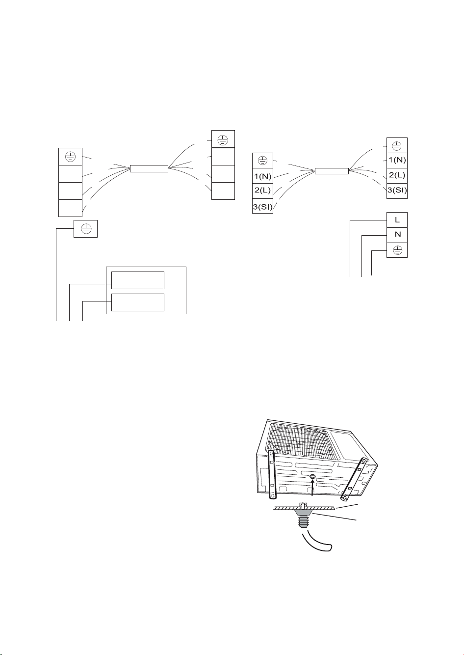
WIRING DIAGRAM
AC L-IN
AC N -IN
1(N)
2(L)
1(N)
3(SI)
2(L)
3(SI)
• 9K/12K Models
• 18K/24K Models
Outdoor unit
Blue (Gray)
Brown
Black
Terminal
Outdoor unit
Terminal
Yellow/Green
Blue (Gray)
Brown
Black
Power connecting
cord
Yellow/Green
Blue (Gray)
Indoor unit
Terminal
Yellow/Green
Blue (Gray)
Brown
Black
Yellow/Green
Power connecting cord
Evaporator
YE/GN
YE/GN
Indoor unit control board
BN
Power supply
BU
Power supply
Note:
For 9k, 12k models, the power supply are connected from indoor unit with a plug.
For 18k, 24k models, the power supply are connected from indoor unit with a circuit breaker.
Indoor unit
Terminal
Brown
Black
BN
BU
OUTDOOR UNIT INSTALLATION
1. Install Drain Port and Drain Hose
The condensate drains from the outdoor unit when
the unit operates in heating mode. In order not to
disturb your neighbours and protect the
environment, install a drain port and a drain hose to
direct the condensate water. Just install the drain
port on the chassis of the outdoor unit, then
connect a drain hose to the port as shown in the
figure on the right .
2. Install and Fix Outdoor Unit
Fix with bolts and nuts tightly on a flat and strong
floor. If installed on the wall or roof, make sure to
fix the supporter well to prevent it from shaking due
to serious vibration or strong wind.
Recommend: it's better to insert rubber pad (optional part) under the ODU foot in order to absorb the
vibration during running.
3. Outdoor Unit Piping Connection
• Remove the valve caps from the 2-way and 3-way valve.
• Connect the pipes to the 2-way and 3-way valves separately according to the required torque.
4. Outdoor Unit Cable Connection (see previous page)
27
Chassis
Drain port
Drain hose
(prepare by user)
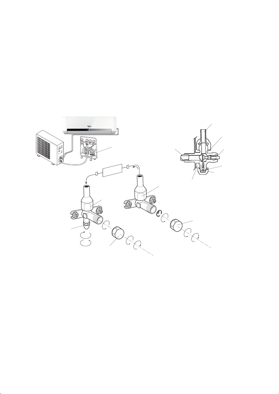
AIR PURGING
Air containing moisture remaining in the refrigeration cycle may cause a malfunction on the compressor.
After connecting the indoor and outdoor units, evacuate air and moisture from refrigerant cycle using a
vacuum pump, as shown below.
Note: Because the system pressure is high and also to protect the environment, be sure not to discharge
the refrigerant to the air directly.
Connect to indoor unit
Open position
Spindle
Needle
Service port cap
Valve cap
(1) Turn
(8) Tighten
Service port
Refrigerant flow direction
(2) Turn
(8) Tighten
Vacuum pump
Indoor unit
3-way valve
(7) Turn to fully
open the valve
Valve cap
(1) Turn
2-way valve
(8) Tighten
3-way valve diagram
Connect to outdoor unit
Valve core
(6) Open 1/4 turn
(7) Turn to fully open the valve
How to Purge Air Tubes:
1. Unscrew and remove caps from 2 and 3-way valves.
2. Unscrew and remove cap from service valve.
3. Connect vacuum pump flexible hose to the service valve.
4. Start vacuum pump for 10-15 minutes until it reaches an absolute vacuum of 10 mm Hg.
5. With vacuum pump still running close the low pressure knob on vacuum pump manifold. Then stop
vacuum pump.
6. Open 2-way valve 1/4 turn, then close it after 10 seconds. Check tightness of all joints using liquid soap
or an electronic leak detector.
7. Turn 2 and 3-way valves stem. Disconnect vacuum pump flexible hose.
8. Replace and tighten all valve caps.
28

AFTER SALES SERVICE
Before contacting the Customer Care Centre:
1. Try to solve the problem yourself based on the
descriptions given in the "Troubleshooting".
2. Turn the appliance off and restart it to see if the
fault persists.
If after carrying out the above checks, the
fault persists, contact the Customer Care
Centre.
Please give:
• a short description of the fault;
• the exact model of the air conditioner;
• the service number (this is the number found
below the word Service on service sticker which
is located on the side or on the bottom of the
indoor unit).
The service number can also be found in the
warranty booklet;
• your full address;
• your telephone number.
If repair work has to be carried out, contact the
Customer Care Centre (Use of original spare
parts and a proper repair is guarenteed).
You will need to present the original invoice.
Failure to comply with these instructions
could compromise the safety and quality of
your product.
29

AVANT D’UTILISER L’APPAREIL
Lisez attentivement toutes les instructions avant d’utiliser ce produit. Afin de réduire le risque d’incendie,
de choc électrique et de blessures corporelles lors de l’utilisation de ce type d’appareil, ces instructions
doivent être systématiquement respectées.
Conservez le présent manuel. Si l’appareil est cédé à un tiers, n’oubliez pas de lui remettre le présent
manuel avec l’appareil.
Ces instructions seront également disponibles sur le site web : www.whirlpool.eu
CONSIGNES DE SÉCURITÉ
•L’installation et la
maintenance/réparation doivent
être réalisées par un technicien
qualifié, conformément aux
instructions du fabricant et aux
normes de sécurité locales. Ne
pas réparer ou remplacer des
pièces de l’appareil sauf indication
contraire spécifique dans les
instructions d’utilisation.
•Ne pas tirer sur le cordon
d’alimentation pour le débrancher
de la prise secteur. Ne pas
tourner ou appuyer sur le cordon
d’alimentation et s’assurer qu’il
n’est pas cassé.
•Ne pas toucher la fiche, le
disjoncteur et le bouton d’arrêt
d’urgence les mains mouillées.
•Ne pas mettre les doigts ou
d’autres objets étrangers dans
l’arrivée ou la sortie d’air des
unités intérieure et extérieure.
•Ne jamais boucher l’arrivée ou la
sortie d’air des unités intérieure et
extérieure.
•Les personnes présentant une
invalidité physique ou mentale, les
enfants et les personnes sans
expérience du produit ont le droit
d’utiliser l’appareil uniquement à
condition d’avoir suivi une
formation spécifique sur la
manière d’utiliser l’appareil par
une personne responsable de leur
sécurité et de leur bien-être.
L’appareil n’est pas destiné à une
utilisation par des personnes
présentant une invalidité et de
très jeunes enfants sans
supervision.
•Les enfants doivent être surveillés
pour s’assurer qu’ils ne jouent pas
avec l’appareil (y compris avec sa
télécommande).
•Cet appareil peut être utilisé par
des enfants de plus de 8 ans et
des personnes atteintes de
déficiences physiques, sensorielles
ou mentales, ayant une
expérience et des connaissances
insuffisantes, uniquement si ces
enfants et personnes sont placés
sous la surveillance d’une
personne responsable ou ont reçu
des instructions sur l’utilisation en
toute sécurité de l’appareil. Les
enfants ne doivent pas jouer avec
l’appareil.
Les enfants ne doivent pas
entreprendre d’opérations de
nettoyage et de maintenance sans
surveillance.
30
 Loading...