

Page 1
Installation Instructions and Use and Care
RH4900 SERIES (shown)
RH4700 SERIES
Part No. 626775/883305 Rev. D
IMPORTANT:
Read and save
these instructions.
IMPORTANT:
Installer: Leave Installation Instructions
with homeowner.
Homeowner: Keep Installation Instructions
for future reference.
Save: Installation Instructions for electrical
inspector’s use.
www.whirlpool.com
30" and 36" Convertible
Range Hood
®
Home Appliances
Page 2
Proper installation is your responsibility.
Make sure you have everything necessary
for correct installation. It is the responsibility
of the installer to comply with the
clearances specified.
Check the location where the range hood
will be installed. The location should be
away from strong draft areas, such as
windows, doors, and strong heating vents.
Mobile home installation
The installation of this range hood must
conform to the Manufactured Home
Construction Safety Standards, Title 24 CFR,
Part 328 (formerly the Federal Standard for
Mobile Home Construction and Safety, Title
24, HUD, Part 280) or when such standard is
not applicable, the Standard for
Manufactured Home Installation 1982
(Manufactured Home Sites, Communities
and Setups) ANSI A225.1/NFPA 501A, or
latest edition, or with local codes.
Important: Observe all governing codes
and ordinances.
Important: Observe all governing codes
and ordinances.
It is the customer’s responsibility:
To contact a qualified electrical
installer.
To assure that the electrical
installation is adequate and in
conformance with National Electrical
Code, ANSI/NFPA 70 — latest edition*,
and all local codes and ordinances.
If codes permit and a separate ground wire
is used, it is recommended that a qualified
electrician determine that the ground path
is adequate.
Do not ground to a gas pipe.
Check with a qualified electrician if you are
not sure range hood is properly grounded.
Do not have a fuse in the neutral or ground
circuit.
Tools and materials
needed for
installation:
Panel A
Electrical requirements
A.
A 115-volt, 60-Hz, AC-only, fused
electrical supply is required. The total
ampere load used, including the range
hood, must not exceed 90% of the rated
capacity of the circuit. The ampere rating
of the range hood is located on the
model/serial number rating plate located
on the side cover of the blower motor
housing.
B.
The range hood must be
connected with copper wire only.
C.
The range hood can be
connected directly to the fused disconnect
(or circuit breaker) box through flexible
armored or nonmetallic sheathed copper
cable. A U.L.-listed strain relief must be
provided at each end of the power supply
cable. Wire sizes (COPPER WIRE ONLY) and
connections must conform with the rating
of the appliance as specified on the
model/serial rating plate.
For power cord connected installations, a
U.L.-listed range hood cord-connection kit
MUST be used. Note: Some models come
with a factory installed 3 ft. long power
cord having a 3-prong ground plug.
Wire sizes must conform to the requirements
of the National Electrical Code ANSI/NFPA
70 — latest edition
*
, and all local codes
and ordinances.
WARNING — TO REDUCE THE RISK OF FIRE,
ELECTRIC SHOCK, OR INJURY TO PERSONS,
OBSERVE THE FOLLOWING:
Installation work and electrical wiring must
be done by qualified person(s) in
accordance with all applicable Codes and
Standards, including Fire Rated
Construction. The combustion airflow
needed for safe operation of fuel-burning
equipment may be affected by this unit’s
operation. Follow the heating equipment
manufacturer’s guideline and safety
standards such as those published by the
National Fire Protection Association
(NFPA),and the American Society of
Heating Refrigeration and Air Conditioning
Engineers (ASHRAE), and the local code
authorities.
When cutting or drilling into wall or ceiling,
do not damage electrical wiring and other
hidden utilities.
Ducted fans must always be vented to the
outdoors.
WARNING — To reduce the risk of fire, use
only metal ductwork.
• compass or 7"
circle template
• pliers
• level
• Phillips screwdriver
• metal snips
• drill
• 1-1/4" drill bit
• pencil
• ruler
• caulking gun
• saber saw
• keyhole saw
• duct tape
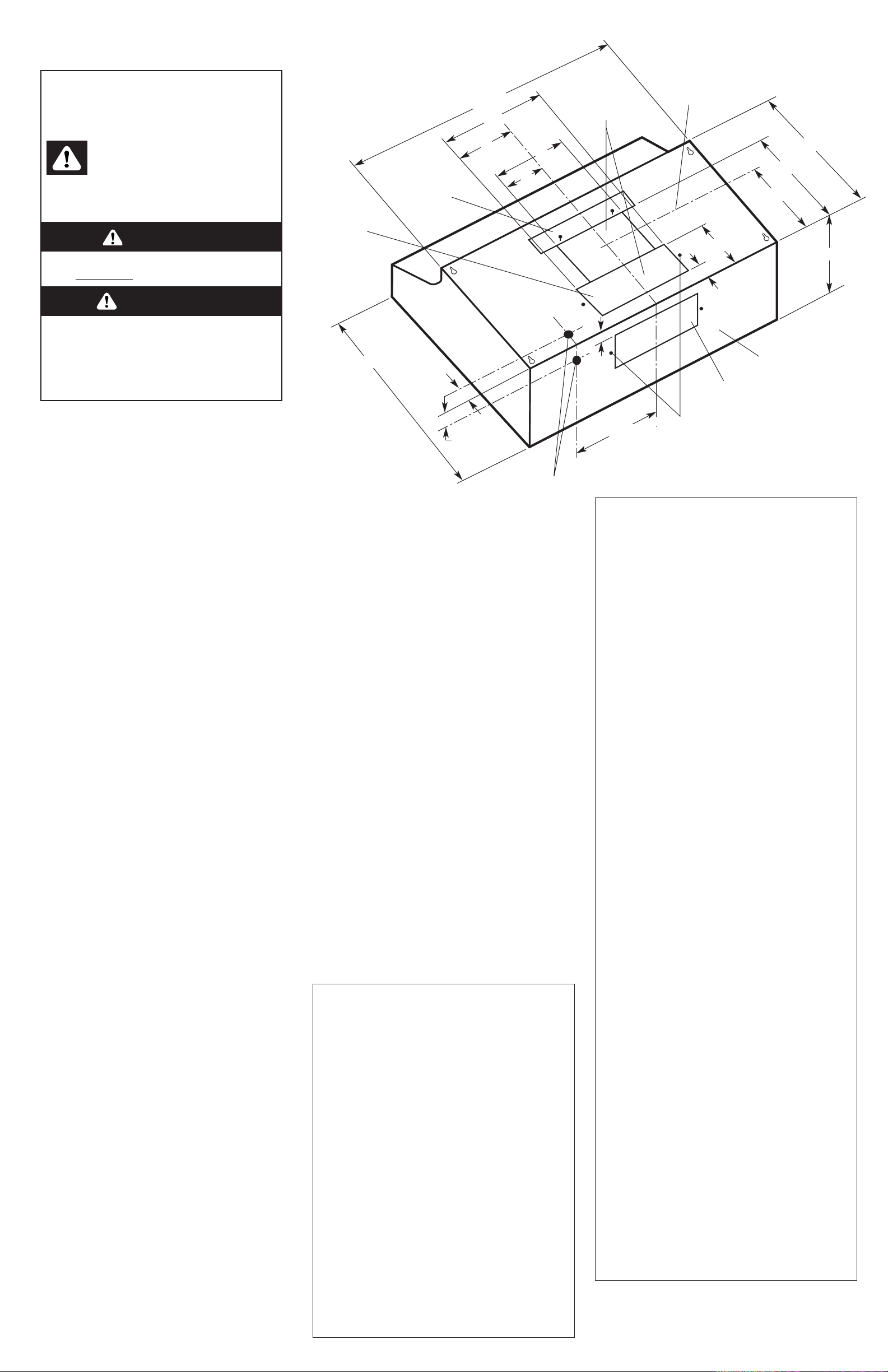
Product dimensions
WARNING — To reduce the risk of fire or
electrical shock, do not use this fan with any
solid-state speed control device.
WARNING — TO REDUCE THE RISK OF FIRE,
ELECTRIC SHOCK, OR INJURY TO PERSONS,
OBSERVE THE FOLLOWING:
Use this unit only in the manner intended by
the manufacturer. If you have questions,
contact the manufacturer. Before servicing
or cleaning unit, switch power off at service
panel and lock switch power off at service
panel and lock service panel to prevent
power from being switched on accidentally.
When the service disconnecting means
cannot be locked, securely fasten a
prominent warning device such as a tag to
the service panel.
CAUTION: For general ventilating use only.
Do not use to exhaust hazardous or explosive
materials and vapors.
WARNING — TO REDUCE THE RISK OF A
RANGE TOP GREASE FIRE:
Never leave surface units unattended at
high settings. Boilovers cause smoking and
greasy spillovers that may ignite. Heat oils
slowly on low or medium settings.
Always turn hood ON when cooking at high
heat or when cooking flaming foods.
Clean ventilating fans frequently. Grease
should not be allowed to accumulate on fan
or filter.
Use proper pan size. Always use cookware
appropriate for the size of the surface
element.
WARNING — TO REDUCE THE RISK OF INJURY
TO PERSONS IN THE EVENT OF A RANGE TOP
GREASE FIRE, OBSERVE THE FOLLOWING:
SMOTHER FLAMES with a close-fitting lid,
cookie sheet, or metal tray, then turn off the
burner. BE CAREFUL TO PREVENT BURNS. If the
flames do not go out immediately, EVACUATE
AND CALL THE FIRE DEPARTMENT.
NEVER PICK UP A FLAMING PAN — You may
be burned.
DO NOT USE WATER, including wet dishcloths
or towels — a violent steam explosion will
result. Use an extinguisher ONLY if:
You know you have a Class ABC extinguisher,
and you already know how to operate it.
The fire is small and contained in the area
where it is started.
The fire department is being called.
You can fight the fire with your back to an
exit.
knockout for
3-1/4 " x 10"
rectangular
back vent
damper
mounting
holes
rear of hood
knockout for
3-1/4 " x 10"
rectangular
top vent
knockouts
for 7" round
venting
for 7"
round vent
vent baffle
wiring knockouts
1-3/8"
4-1/4"
7-1/2"
1/4"
1-3/8"
7"
8"
4"
5"
1"
12"
9"
19-3/4"
30" model: 29-7/8"
36" model: 35-7/8"
4 1/2"
10"
This is the safety alert symbol.
This symbol alerts you to potential hazards
that can kill or hurt you and others.
All safety messages will follow the safety alert
symbol and either the word “DANGER” or
“WARNING”. These words mean:
Before you start...
You can be killed or seriously injured if you
don’t follow instructions.
D ANGER
WARNING
Your safety and the safety of others
are very important.
We have provided many important safety
messages in this manual and on your appliance.
Always read and obey all safety messages.
All safety messages will tell you what the potential
hazard is, tell you how to reduce the chance of
injury, and tell you what can happen if the
instructions are not followed.
You can be killed or seriously injured if you
don’t immediately follow instructions.
Copies of standards listed may be obtained from:
* National Fire Protection Association
Batterymarch Park
Quincy, Massachusetts 02269
Page 3
Recommended vent length
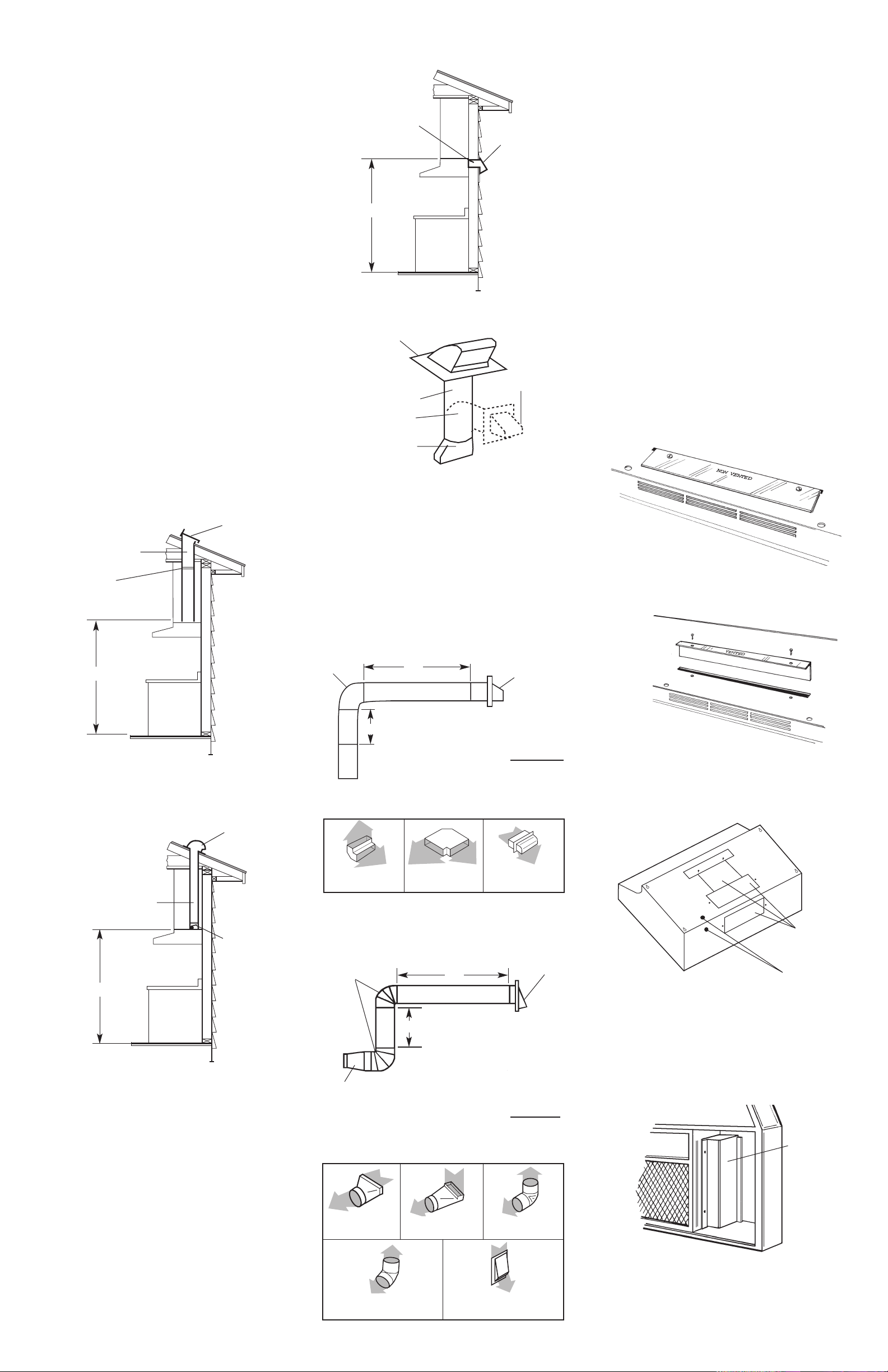
Use 3-1/4" x 10" or 7" vent with a maximum
length of 26 feet for vent system. For best
performance, use no more than three 90°
elbows. To calculate the length of system
you need, add the equivalent feet for
each vent piece used in the system. See
the following examples.
Figure 1
Panel B
7" round
through roof
roof cap
66"
66"
3-1/4" x 10"
through the roof
roof cap
3-1/4" x 10"
damper
damper located
as far from hood
as possible
Vertical roof venting
wall cap
66"
3-1/4" x 10"
through the wall
Vertical roof venting
Horizontal wall venting
roof cap
wall cap
elbows
3-1/4" x 10" to round
vent transition
7" min. diameter
round vent
Figure 4
Figure 3
6.
Remove terminal box cover from range
hood.
Figure 2
3-1/4" x 10" vent system
Recommended standard fittings
7" vent system
90° elbow
wall cap
3-1/4" x 10"
to 7"
transition
Maximum length = 26 feet
1 - transition = 4.5 ft.
2 - 90° elbows = 10 ft.
1 - wall cap = 0 ft.
8 feet straight = 8 ft.
Length of 7" system = 22.5 ft.
Maximum length = 26 feet
1 - 90° elbow = 5 ft.
8 feet straight = 8 ft.
1 - wall cap = 0 ft.
Length of 3-1/4" x
10" system = 13 ft.
Recommended standard fittings
6 ft.
2 ft.
3-1/4" x 10" 90°
elbow = 5 ft.
3-1/4" x 10" flat
elbow = 12 ft.
3-1/4" x 10" wall
cap = 0 ft.
3-1/4" x 10" to
7" = 4.5 ft.
90° elbow = 5 ft.
45° elbow = 2.5 ft.
3-1/4" x 10" to 7"
90° elbow = 5 ft.
7" wall cap = 0 ft.
Vented installation
Now start...
With range hood in kitchen.
Slide cardboard or hardboard under range
before moving range across floor to
prevent damaging floor covering.
Cover countertop, cooktop or set-in range
with a thick, protective covering to prevent
damaging countertop.
1.Disconnect and move freestanding
range from cabinet opening to provide
easier access to upper cabinet and rear
wall. Put a thick, protective covering over
cooktop, set-in range or countertop to
protect from damage or dirt.
2.Determine which venting method
(roof or wall venting or non-venting) you
need to use. This range hood is shipped for
non-vented installation.
If non-venting (recirculating) installation is
desired, follow instructions on Panel D.
terminal
box
cover
2 ft.
6 ft.
wall cap
3-1/4" x 10"
elbow
Venting requirements
Venting system must terminate to the
outside.
Do not terminate the vent in an attic or
other enclosed space.
Do not use four-inch laundry-type wall
caps.
Do not use plastic vent.
Vent system needed for installation is not
included. Wall or roof caps used must have
backdraft damper.
Determine which outside venting method
needs to be used. NOTE: If a non-vented
(recirculating) installation is desired, follow
instructions on Panel D.
The length of the vent system and number
of elbows should be kept to a minimum to
provide efficient performance. The size of
the vent system should be uniform. Do Not
install two elbows together. Use duct tape
to seal all joints in the vent system. Vent
system can terminate either through the
roof or wall. Use caulking to seal exterior
wall or roof opening around exhaust hood.
For the most efficient and quiet operation, it
is recommended that the range be vented
vertically through the roof through 7" round
vent system.
Figures 1-4 show common venting methods
and what types of materials are needed.
3.
Remove screws from vent baffle on
top of range hood. Remove vent baffle.
4.
Turn vent baffle and reinsert in slot in top of
range hood so that the word “Vented” is
facing up. Fasten vent baffle with screws.
wiring
knockouts
vent
knockouts
5.
Remove knockout from the wiring opening
(top or rear) to be used.
For rectangular venting, remove only the
3-1/4" x 10" rectangular opening knockout.
For round ventwork venting through roof,
remove both opening knockouts.
Page 4
Panel C
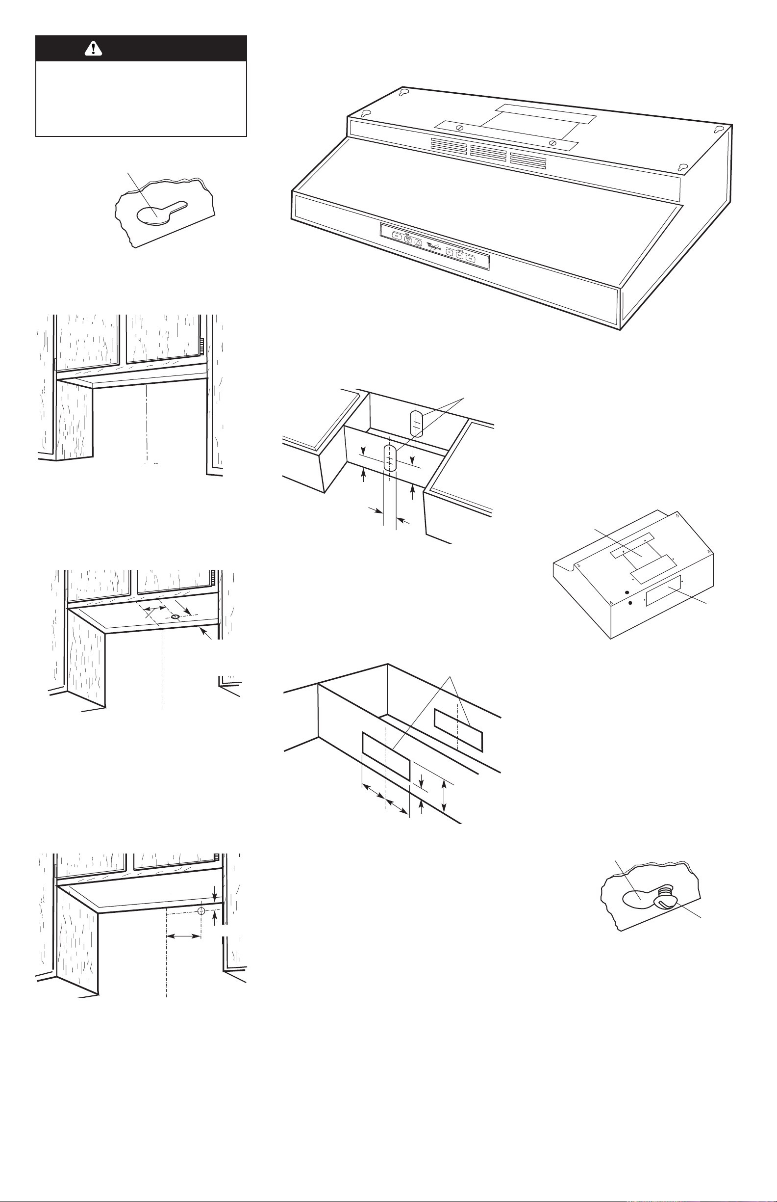
9.
To wire through top, mark a line 7-1/2" from
the right of the centerline on the underside
of the cabinet. Mark the point on this line
that is 1-3/8" from back wall. Drill a 1-1/4"
diameter hole through the cabinet at this
point. Note: If a cord-connection kit is used,
drill a 1-5/8" diameter hole.
8.
Determine and clearly mark a vertical
centerline on the wall and cabinet in the
area the vent opening will be made.
7-1/2"
centerline
7-1/2"
centerline
1-3/8"
7. Lift the range hood into final
position and center. Mark on the underside
of cabinet the location of the four keyhole
mounting slots. Set range hood aside on a
protected surface.
keyhole slot
front
of hood
To wire through rear, mark a line 7-1/2" from
the right of the centerline on the wall. Mark
the point on this line that is 1-3/8" from
underside of cabinet. Drill a 1-1/4"
diameter hole through wall at this point.
1-3/8"
from wall
(not cabinet
frame)
To vent through the roof with 3-1/4" x 10"
rectangular vent, mark a line 1" and 5" from
the back wall on the underside of the
cabinet. Mark lines 5-1/4" to the right and
left of the centerline on the underside of
cabinet that connect the lines just drawn.
Use a keyhole saw and saber saw to cut a
rectangular opening for the ventwork.
Repeat for the underside of the top of the
cabinet.
To vent through wall with 3-1/4" x 10"
rectangular vent, measure 1/8" and
3-5/8" down from underside of cabinet and
mark on back wall. Measure and mark a
line 5-1/4" to right and left of centerline,
connecting the two lines. Use a keyhole
saw and saber saw to cut a rectangular
opening for the ventwork.
10 .
To vent through the roof with 7" round vent,
mark 4-1/2" and 5" in from back wall along
the centerline on underside of cabinet. Use
these points as centers to draw 7-1/8"
circles on underside of cabinet. Use a saber
saw to cut the openings for the ventwork.
Repeat for the underside of the top of the
cabinet. This will create slotted openings
which makes it easier to install the vent
system.
cabinet
cutouts
4-1/2"
5"
7-1/8"
cabinet cutouts
1"
5-1/4"
5-1/4"
5"
Numbers correspond
to steps.
4.
7.
12.
14. 15.
5.
6. 16. 17.
7. 14. 15.
RH4900 Series
Shown
3.
15. 16.
keyhole slot
screw
11 .
Install vent system through the vent opening
in upper cabinet or wall. Complete venting
system according to method needed. See
“Venting requirements.” Use caulking to seal
exterior wall or roof opening.
12 .
Attach rectangular damper to selected
rectangular vent opening. If damper is
attached to back of range hood, be sure
damper hinge is toward the top. For round
vented installations, use round damper in
vent to prevent air from flowing back into
ventwork. If wall or roof cap has a damper,
remove damper blade from range hood.
13 .
Do Not turn on power until installation is
complete. Run wiring through wall or
cabinets according to the National Electrical
Code and local codes and ordinances.
14 .
Start screws through neck of each of the
four keyhole mounting screw slots marked
on the cabinet bottom.
round
damper
damper
15 .
Lift range hood into final position, feeding
electrical wire through wiring opening.
Position the range hood so that the large
end of the keyhole slots are over the screws.
Then push the hood toward the wall so that
the screws are in the neck of the slots.
Tighten mounting screws to cabinet, making
sure mounting screws are in narrow neck of
slots. Make sure that damper blade, if used,
rotates up and down freely.
Excessive Weight Hazard
Use two or more people to move and
install range hood.
Failure to follow this instruction can
result in back or other injury.
WARNING
centerline
centerline
Page 5
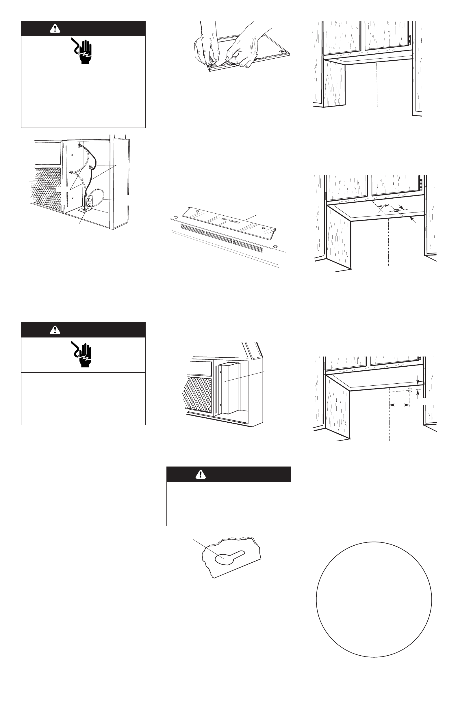
Electrical Shock Hazard
Disconnect power before making
electrical connections.
Connect ground wire to green ground
screw in terminal box.
Failure to do so can result in death or
electrical shock.
WARNING
Panel D
6.
To wire through top, mark a line
7-1/2" from the right of the centerline on
the underside of the cabinet. Mark the
point on this line that is 1-3/8" from the back
wall. Drill a 1-1/4" diameter hole through
cabinet at this point. Note: If a cordconnection kit is used, drill a 1-5/8"
diameter hole.
7-1/2"
centerline
1-3/8"
from wall,
(not
cabinet
frame)
16 .
For models requiring direct wiring:
Connect the white and black wires of the
power supply cable to the white and black
leads in the hood with twist-on connectors.
Connect the power supply ground wire to
the green ground screw inside the terminal
box.
Use caulking to seal wire opening.
Replace terminal box cover.
18 .
Pull firmly on tab to remove filter/light lens
from range hood. Turn filter/light lens so that
charcoal filter pad is facing up. Lift tabs and
remove charcoal filter pad. Discard
charcoal filter pad. Place edge of filter/light
lens in opening so that right side is above
flange and tab faces downward. Press
filter/light lens into position.
white
green
ground
screw
ground
wire
black
1.
Check vent baffle on top of range
hood. “Non-vented” should be facing up.
2.
Remove knockout from the wiring opening
(rear or top) to be used.
Do Not remove venting knockouts.
Non-vented installation
vent baffle
3.
Remove terminal box cover from range
hood.
terminal
box
cover
keyhole slot
4.
Lift range hood into final position and
center. Mark on underside of cabinet the
location for the four keyhole mounting
slots. Set range hood aside on a protected
surface.
5.
Determine and clearly mark a vertical
centerline in the cabinet opening.
7-1/2"
centerline
1-3/8"
To wire through rear, mark a line 7-1/2" from
the right of the centerline on the wall. Mark
the point on this line that is 1-3/8" from
underside of cabinet.
You have just
finished installing
your new Whirlpool range hood.
Keep Installation Instructions
close to range hood for easy
reference. The instructions will
make reinstalling your Whirlpool
range hood in another home
as easy as the first
installation.
Congratulations!
7.
Continue installation with Step 13, on
Panel C.
Excessive Weight Hazard
Use two or more people to move and
install range hood.
Failure to follow this instruction can
result in back or other injury.
WARNING
centerline
centerline
Electrical Shock Hazard
Plug into a grounded 3-prong outlet.
Do not remove ground prong.
Do not use an adapter.
Failure to follow these instructions can
result in death, fire, or electrical shock.
WARNING
For your personal safety, this range hood
must be grounded. To minimize possible
shock hazard, the cord must be plugged
into a mating, 3-prong, ground-type outlet,
grounded in accordance with National
Electrical Code, ANSI/NFPA 70 – latest
edition* and all local codes and
ordinances.
If mating outlet is not available, it is the
responsibility and obligation of the
customer to have a properly grounded, 3prong outlet installed by a qualified
electrician.
Do not use an extension cord.
Using a U.L.-listed power supply
cord-connection kit:
Follow Power Cord Kit instructions for
connecting wiring.
Replace terminal box cover.
17 . Turn power supply on.
For cord connected models:
Copies of standards listed may be obtained from:
* National Fire Protection Association
Batterymarch Park
Quincy, Massachusetts 02269
Page 6
Use & Care
Information
Use this range hood only in the manner
intended by the manufacturer. If you have
any questions, contact the manufacturer.
Before installation and before servicing or
cleaning range hood, switch off power at
service panel and lock service panel to
prevent power from being switched on
accidentally. When the servicedisconnecting means cannot be locked,
securely fasten a prominent warning
device, such as a tag, to the service panel.
For best results, turn range hood fan ON at
beginning of cooking and allow it to run
until all smoke and odors are removed from
room.
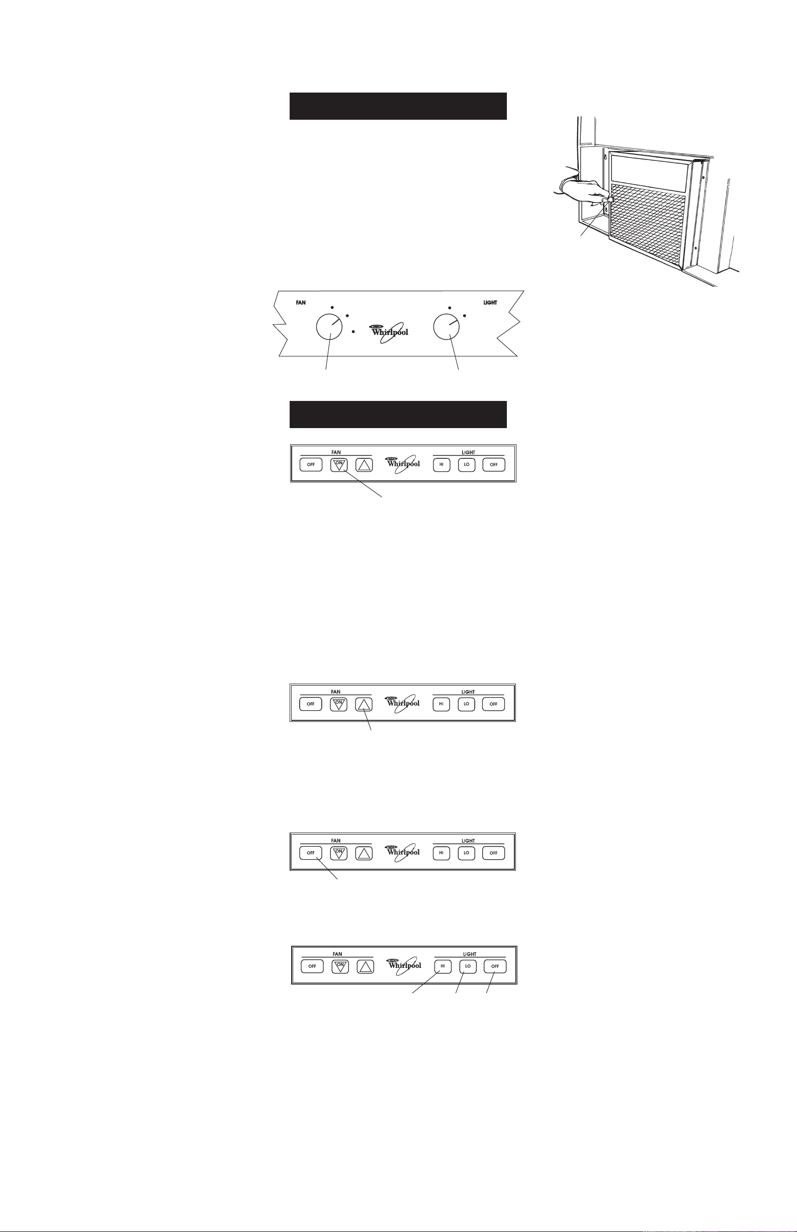
To turn fan ON, HIGH and LOW:
Turn fan control to turn fan to HIGH, LOW
and OFF. Speed may be increased or
decreased anytime during range hood
operation.
To turn range hood light ON and OFF:
Turn light control to ON or OFF. Light may
be turned off or on anytime during range
hood operation.
Panel E
Operation of range hood
RH4700XD Series
RH4900XD Series
On pad
UP ARROW pad
OFF pad
HI pad LO pad OFF pad
To operate fan:
Press “ON” pad. The range hood fan will
start at the highest fan speed. To change
fan to lowest speed, press the “DOWN
ARROW” pad. Speed may be increased or
decreased anytime during range hood
operation.
To decrease fan speed:
Press “ON” pad several times until fan
reaches desired speed. Each time the
“ON” pad is pressed, fan speed will
decrease until fan reaches lowest setting.
To increase speed:
Press “UP ARROW” pad until fan reaches
desired speed. Each time the “UP ARROW”
pad is pressed, fan speed will increase until
fan reaches highest speed.
To turn fan OFF:
Press fan “OFF” pad.
To operate light:
Press “HI” pad for bright light. Press “LO”
pad for less light. Light may be changed to
“HI” or “LO” during anytime of range hood
operation.
To turn light OFF:
Press light “OFF” pad.
Care of range hood
Filter/light lens:
For best results, remove and clean often.
To remove filter/light lens:
Pull firmly on filter tab to remove filter/light
lens from range hood.
To clean filter/light lens:
Place filter/light lens in dishwasher or hot
sudsy water to clean.
Non-vented installation:
Turn filter/light lens so that charcoal filter
pad is facing up. Lift tabs and remove
charcoal filter pad. Discard charcoal filter
pad. Place filter/light lens in dishwasher or
hot sudsy water to clean. Lift tabs and
place new charcoal filter pad in filter/light
lens.
To reinstall filter/light lens:
Place edge of filter/light lens in opening so
that right side is above flange and tab
faces downward. Press filter/light lens into
position.
When it's time to replace your
aluminum filter/light lens, or charcoal filter
pads:
1. For model series RH4700 and RH4900:
Order Aluminum Filter/Light Lens
no. 883149.
Order Charcoal Filter Pads no. 883151.
2. Call Whirlpool's Telesales line at
1-800-442-9991.
3. Give the Telesales Representative the
part number needed.
4. The Representative will give you the
current price.
5. Place your order using your Master
Card
®
, Visa®or Discover® credit card.
6. If you wish: mail a check or money order
to:
Whirlpool Corporation
1900 Whirlpool Drive
LaPorte, IN 46350-9980
Attn: Accessory Accounting
7. Be sure to ask the Telesales
Representative about the wide variety
of other Whirlpool Product Accessories.
To clean blower motor:
Clean exterior of motor with a damp cloth
and grease-cutting detergent.
Exterior surfaces
Clean the range hood with a mild
detergent and soft cloth. Do Not use
abrasive cleansers or steel wool pads.
Light
Do Not use bulb larger than 60 watts in light
socket.
Light bulb is not included.
filter tab
OFF
OFF
HI
LO
ON
fan control
light control
Whirlpool perfect Logo small
Page 7
WHIRLPOOL CORPORATION SHALL NOT BE LIABLE FOR INCIDENTAL OR CONSEQUENTIAL DAMAGES. Some
states do not allow the exclusion or limitation of incidental or consequential damages so this limitation or
exclusion may not apply to you. This warranty gives you specific legal rights, and you may also have
other rights which vary from state to state.
Outside the United States, a different warranty may also apply. For details, please contact your
franchised Whirlpool distributor or military exchange.
Part No. 626775/883305 Rev. D
© 2000 Whirlpool Corporation
® Registered Trademark/SM Trademark of Whirlpool, U.S. A.
Benton Harbor, Michigan 49022
Printed in U.S.A.
Whirlpool® Range Hood Warranty
LENGTH OF WARRANTY
WHIRLPOOL WILL NOT PAY FOR
WHIRLPOOL WILL PAY FOR
FULL ONE-YEAR WARRANTY
From date of purchase
FSP
®
replacement parts and repair labor to correct
defects in materials or workmanship. Service must
be provided by an authorized WhirlpoolSMservice
company.
A. Any labor costs incidental to the replacement of defective parts.
B. Consumable parts such as light bulbs and filters.
C. Service calls to:
1. Correct the installation of the range hood.
2. Instruct you how to use the range hood.
3. Replace house fuses or correct house wiring.
D. Repairs when range hood is used in other than normal, single-family household use.
E. Pickup and delivery. This product is designed to be repaired in the home.
F. Damage to range hood caused by accident, misuse, fire, flood, act of God or use of
products not approved by Whirlpool.
If range hood does not operate...
Check that the circuit breaker is not tripped
or the house fuse blown.
If you need
assistance...
The Whirlpool Consumer Assistance Center
will answer any questions about operating
or maintaining your range hood not
covered in the Installation Instructions. The
Whirlpool Consumer Assistance Center is
open 24 hours a day, 7 days a week. Just
dial 1-(800) 253-1301 — the call is free.
When you call, you will need the range
hood model number and serial number.
Both numbers can be found on the
model/serial rating plate located on the
side cover of the motor housing.
If you need
service...
In the event your Whirlpool appliance
should need service, call the dealer from
whom you purchased the appliance or a
Whirlpool-authorized service company. A
Whirlpool-authorized service company is
listed in the Yellow Pages of your phone
directory under “Appliance — Household
— Major — Service and Repair.” You can
also obtain the service company’s name
and number by dialing, free, within the
continental United States, the Whirlpool
Consumer Assistance Center number,
1-(800) 253-1301. A special operator will tell
you the name and number of your nearest
Whirlpool-authorized service company.
Maintain the quality built into your Whirlpool
appliance — call a Whirlpool-authorized
service company.
CORPORATION
 Loading...