

Whirlpool RB770PXT1 Installation Manual
ELECTRIC BUILT-IN
SELF CLEANING SINGLE
AND DOUBLE OVEN MODELS
I
Part No. 5606031 PO6/P238-3751816259 Rev. C
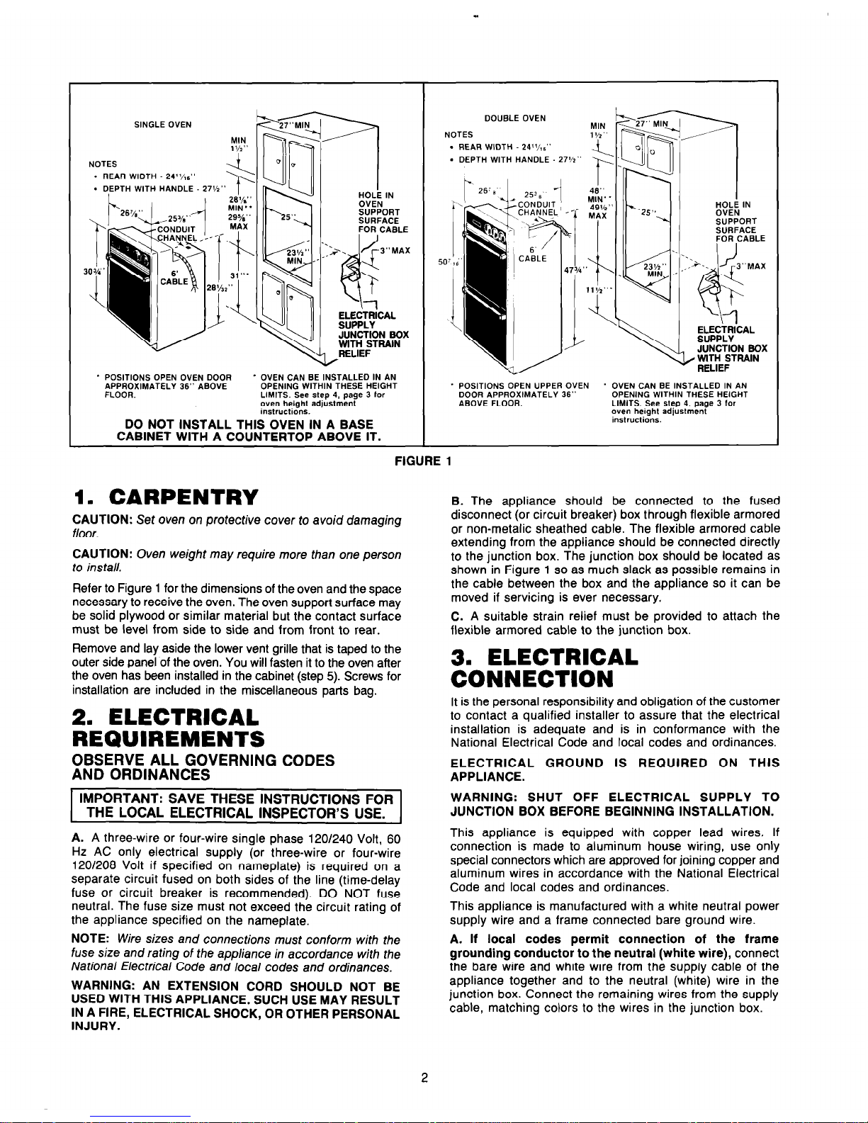
SINGLE OVEN
y, iyq$$$$
NOTES
. REAR WIDTH - 24’/,:
l
DEPTH WITH HANDLE 27%”
SUPPORT
’ POSITIONS OPEN OVEN DOOR
APPROXIMATELY 36” ABOVE
FLOOR.
* OVEN CAN BE INSTALLED IN AN
OPENING WITHIN THESE HEIGHT
LIMITS. See step 4, page 3 lor
oven height adjustmenl
instructions.
DO NOT INSTALL THIS OVEN IN A BASE
CABINET WITH A COUNTERTOP ABOVE IT.
DOUBLE OVEN
NOTES
. REAR WIDTH 24’%.“
. DEPTH WITH HANDLE 27%“
WITH STRAIN
* POSITIONS OPEN UPPER OVEN ’ OVEN CAN BE INSTALLED IN AN
DOOR APPROXIMATELY 36” OPENING WITHIN THESE HEIGHT
ABOVE FLOOR.
LIMITS. See step 4. page 3 for
oven height adjustment
instructions.
FIGURE 1
1.
CARPENTRY
CAUTION: Set oven on protective cover to avoid damaging
floor.
CAUTION: Oven weight may require more than one person
to install.
Refer to Figure 1 for the dimensions of the oven and the space
necessary to receive the oven. The oven support surface may
be solid plywood or similar material but the contact surface
must be level from side to side and from front to rear.
Remove and lay aside the lower vent grille that is taped to the
outer side panel of the oven. You will fasten it to the oven after
the oven has been installed in the cabinet (step 5). Screws for
installation are included in the miscellaneous parts bag.
2. ELECTRICAL
REQUIREMENTS
OBSERVE ALL GOVERNING CODES
AND ORDINANCES
IMPORTANT: SAVE THESE INSTRUCTIONS FOR
THE LOCAL ELECTRICAL INSPECTOR’S USE.
A. A three-wire or four-wire single phase 120/240 Volt, 60
Hz AC only electrical supply (or three-wire or four-wire
120/208 Volt if specified on nameplate) is required on a
separate circuit fused on both sides of the line (time-delay
fuse or circuit breaker is recommended). DO NOT fuse
neutral. The fuse size must not exceed the circuit rating of
the appliance specified on the nameplate.
NOTE: Wire sizes and connections must conform with the
fuse size and rating of the appliance in accordance with the
National Electrical Code and local codes and ordinances.
WARNING: AN EXTENSION CORD SHOULD NOT BE
USED WITH THIS APPLIANCE. SUCH USE MAY RESULT
IN A FIRE, ELECTRICAL SHOCK, OR OTHER PERSONAL
INJURY.
B. The appliance should be connected to the fused
disconnect (or circuit breaker) box through flexible armored
or non-metalic sheathed cable. The flexible armored cable
extending from the appliance should be connected directly
to the junction box. The junction box should be located as
shown in Figure 1 so as much slack as possible remains in
the cable between the box and the appliance so it can be
moved if servicing is ever necessary.
C. A suitable strain relief must be provided to attach the
flexible armored cable to the junction box.
3. ELECTRICAL
CONNECTION
It is the personal responsibility and obligation of the customer
to contact a qualified installer to assure that the electrical
installation is adequate and is in conformance with the
National Electrical Code and local codes and ordinances.
ELECTRICAL GROUND IS REQUIRED ON THIS
APPLIANCE.
WARNING: SHUT OFF ELECTRICAL SUPPLY TO
JUNCTION BOX BEFORE BEGINNING INSTALLATION.
This appliance is equipped with copper lead wires. If
connection is made to aluminum house wiring, use only
special connectors which are approved for joining copper and
aluminum wires in accordance with the National Electrical
Code and local codes and ordinances.
This appliance is manufactured with a white neutral power
supply wire and a frame connected bare ground wire.
A. If local codes permit connection of the frame
grounding conductor to the neutral (white wire), connect
the bare wire and white wire from the supply cable of the
appliance together and to the neutral (white) wire in the
junction box. Connect the remaining wires from the supply
cable, matching colors to the wires in the junction box.
 Loading...