

Whirlpool KEHS01PMT2 Parts Diagram

TECH SHEET – DO NOT DISCARD PAGE 1
WARNING
Electrical Shock Hazard
Disconnect power before
servicing.
Replace all parts and panels
before operating.
Failure to do so can result in
death or electrical shock.
DIAGNOSTIC GUIDE
Before servicing, check the following:
Make sure there is power at the wall outlet.
■
Has a household fuse blown or circuit breaker
■
tripped? Time delay fuse?
Is dryer vent properly installed and clear of lint
■
or obstructions?
All tests/checks should be made with a VOM
■
(volt-ohm-milliammeter) or DVM
(digital-voltmeter) having a sensitivity of
20,000 ohms per volt DC or greater.
Check all connections before replacing
■
components. Look for broken or loose wires,
failed terminals, or wires not pressed into
connectors far enough.
■ A potential cause of a control not functioning
is corrosion on connections. Observe
connections and check for continuity with an
ohmmeter.
■ Connectors: Look at top of connector. Check
for broken or loose wires. Check for wires not
pressed into connector far enough to engage
metal barbs.
■
Resistance checks must be made with dryer
unplugged or power disconnected.
DIAGNOSTIC TESTS
These tests allow factory or service personnel to test
and verify all inputs to the machine control
electronics. You may want to do a quick and overall
checkup of the dryer with these tests before going
to specific troubleshooting tests.
ACTIVATING THE DIAGNOSTIC TEST
MODE
1. Be sure the dryer is in standby mode (plugged in
and all indicators off).
2. Press the following button sequence:
+ (more time), – (less time), + (more time),
– (less time), all within 5 seconds.
3. All indicators on the console are illuminated with
88 showing in the Estimated Time Remaining
(two-digit) display, if this test mode has been
entered successfully.
IMPORTANT
Electrostatic Discharge (ESD) Sensitive Electronics
ESD problems are present everywhere. ESD may damage or weaken the electronic
control assembly. The new control assembly may appear to work well after repair is
fin is hed, but failure may occur at a later date due to ESD stress.
Use an anti-static wrist strap. Connect wrist strap to green gr ou nd connecti on
■
point or unpainted metal in the appliance
Touch your finger repeatedly to a green ground connecti on point or u npainted
metal in the appliance.
Before removing the part from its package, touch the anti-static bag to a green
■
ground con nection point or unpainted metal in the appliance.
Avoid touching electronic parts or terminal contacts; handle electronic control
■
assembly by edges only.
When repackaging failed electronic control assembly in anti-static bag, observe
■
above instructions.
If unsuccessful entry into diagnostic
mode, actions can be taken for
specific indications:
Indication 1: None of the indicators
or display turns on.
Action:
Select any manual cycle.
If indicators come on, then try to
➔
change the dryer time by pressing the
+ and – buttons. If either button fails to
change the time, something is faulty
with one of those buttons, and it is not
possible to enter the diagnostic mode.
Remove the console electronics and
housing. See Accessing & Removing
the Electronic Assemblies, page 7.
➔
If no indicators come on after pressing
the Manual cycle buttons, go to
TEST #1, page 3.
Indication 2: E1 or E2 flashes from
the display.
Action:
Proceed to TEST #3a, page 4.
Indication 3: E3 flashes from the
display.
Action:
Check that the correct machine
control electronics and console
electronics and housing are installed. Do
so by removing these components to view
the part numbers and compare them to
the part numbers in the Service Parts List
-OR-
for this unit. See Accessing & Removing
the Electronic Assemblies, page 7.
Replace components if necessary.
Diagnostic: Console switches and
indicators
Pressing each button or turning the cycle
selector to each cycle should cause a beep
tone and control one or more LEDs as shown
in figure 1, page 3. Pressing the Hold To Start
button will also control the motor and heater,
while the two-digit display will indicate a
software project i.d. number.
Diagnostic: Moisture Sensor
Locate two metal strips on the face of the lint
screen housing. Bridge these strips with a
wet cloth or a finger.
➔
If a beep is heard and a software
revision number is displayed on the
console, the sensor is OK.
➔
If not, or if a beep tone is heard before
bridging the moisture strips, go to
TEST#4,step2,page5.
Diagnostic: Door Switch
Opening the door should cause a beep tone
and a number and letter to be indicated in the
two-digit display. Closing the door firmly
should cause a beep tone and the display to
go blank or indicate
88.
DISPLAY FAULT/ERROR CODES
The error codes below would be indicated when attempting to start a drying cycle, or after
activating the diagnostic test mode.
DISPLAY DESCRIPTION EXPLANATION AND RECOMMENDED PROCEDURE
PF flashes to indicate that a power failure occurred while the dryer
PF
E1
POWER FAILURE
THERMISTOR OPEN
was running. Press HOLD TO START to continue the cycle, or press
OFF/Pause to clear the display.
E1 flashes if the thermistor is open. See TEST #3a, page 4.
THERMISTOR SHORTED
E2
E3
USER INTERFACE OR
SOFTWARE MISMATCH
E2 flashes if the thermistor has shorted. See TEST #3a, page 4.
E3 flashes when there is a keyswitch or software mismatch. This
error code will ONLY appear when in the diagnostic test mode.
See TEST #5, page 6.
FOR SERVICE TECHNICIAN’S USE ONLY PART NO. 8563816 REV. B
PAGE 2 TECH SHEET – DO NOT DISCARD
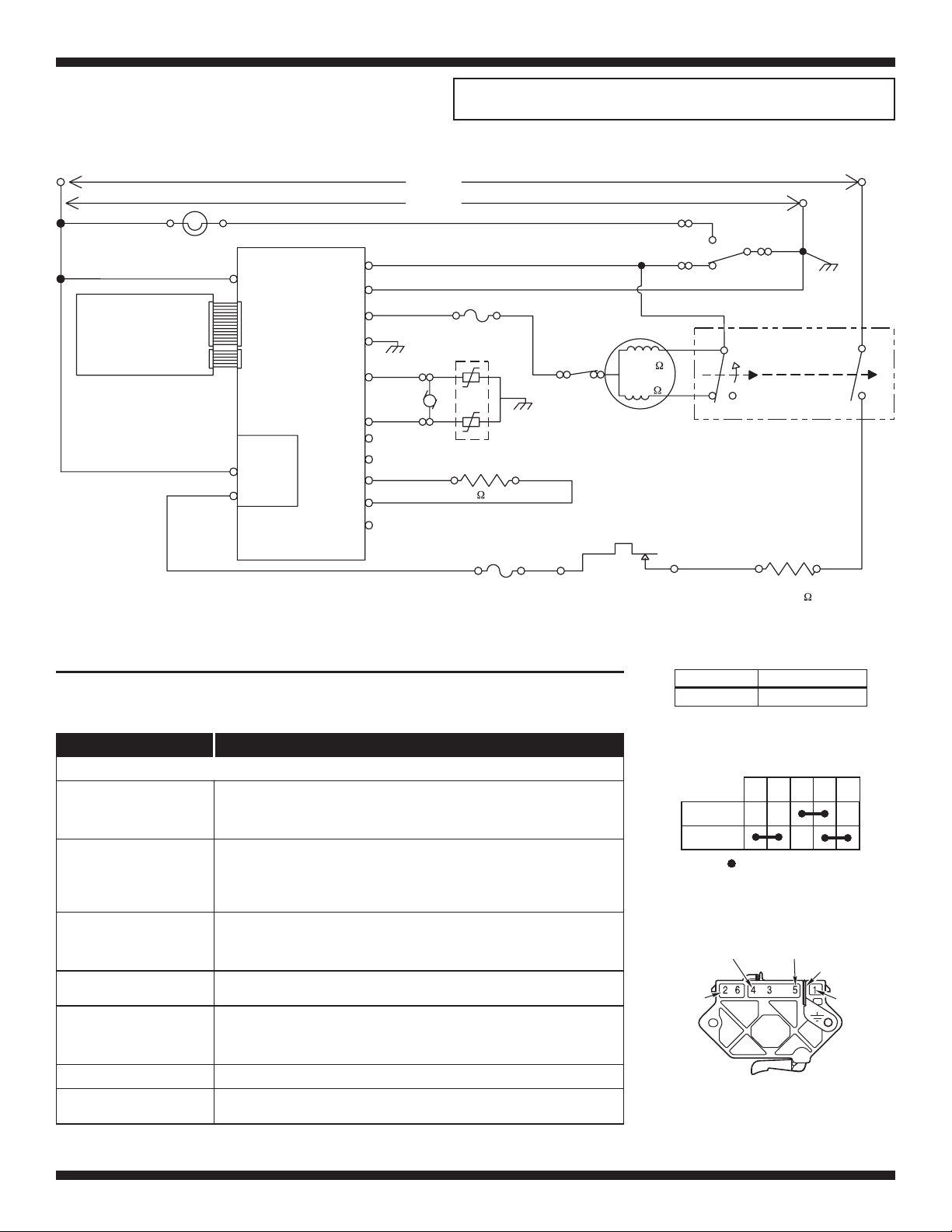
ELECTRIC DRYER WIRING DIAGRAM
L1 LINE – BK
BK
DRUM LAMP
BK
USER INTERFACE
(ACTIVE OVERLAY or
ALTERNATE TECHNOLOGY)
(0.250 TERMINAL)
(0.250 TERMINAL)
P1-5
N.O.
COM
DL
L1
P3
P4
HEATER
RELAY
HEATER +V
HEATER RTN
ELECTRONIC
CONTROL
BR
DOOR
NEUTRAL
MOTOR
PT-1
MOIST.
MOIST RTN
MODEL
MODEL RTN
TEMP.
TEMP RTN
N.C.
P1-3
P1-2 NEUTRAL
P1-4
P1-1
P2-1
P2-2
P2-3
P2-4
P2-5
P2-6
P2-7
240 VOLTS
120 VOLTS
LBU
G-Y
Y- R
SENSOR
BK
R-W
BK
IMPORTANT: Electrostatic (static electricity) discharge may cause damage
to electronic control assemblies. See page 1 for details.
R – LINE L2
W
LBU
THERMAL FUSE
196° F (91° C)
SENSOR
MOVS
THERMISTOR
10k ± 3%
R
THERMAL CUT-OFF
(TCO) 352° F (178° C)
G-Y
BK
W
4M
BELT
SWITCH
HIGH LIMIT
THERMOSTAT
295° F (146° C)
– NEUTRAL
BU
MAIN
2.4– 3.6
START
2.4– 3.8
DRIVE MOTOR
1/3 H.P.
NC
BU
DOOR
SWITCH
W
5M
CENTRIFUGAL SWITCH
3M
6M
R-W
W
HEATER
–11.8
7.8
NEUTRAL
TERMINAL
LINKED TO
CABINET
W
2M
1M
R
TROUBLESHOOTING GUIDE
Some tests will require accessing components. See figure 13, page 7 for component locations.
PROBLEM POSSIBLE CAUSE / TEST
NOTE: Possible Cause/Tests MUST be performed in the sequence shown for each problem.
WON’T POWER UP.
(No response when Control
On button is pressed.)
WON’T START CYCLE
WHEN HOLD TO START
BUTTON IS PRESSED.
WON’T SHUT OFF WHEN
EXPECTED.
CONTROL WON’T ACCEPT
SELECTIONS.
WON’T HEAT.
HEATS IN AIR CYCLE.
SHUTS OFF BEFORE
CLOTHES ARE DRY.
1. Supply Connections. See TEST #1, page 3.
2. Check harness connections.
3. Console electronics and housing. See TEST #5, page 6.
1. If number display flashes, check to be sure the door is completely shut,
and press and hold down HOLD TO START for about 1 second.
2. See TEST #2, page 3.
3. See TEST #6, page 6.
1. Check OFF/Pause button. See TEST #5, page 6.
2. Console electronics and housing. See TEST #5, page 6.
3. Moisture Sensor. See TEST #4, page 5.
Console electronics and housing. See TEST #5, page 6.
1. Heater. See TEST #3, page 4.
2. Check harness connections.
3. Check installation.
Thermistor. See TEST #3a, page 4.
Moisture Sensor. See TEST #4, page 5.
Drum Size: Drum Speed:
7.0 cubic feet
51.5 ± 3 RPM CW
Contacts
Function
1M 2M 3M 5M 6M
Start
Run
=
Contacts closed
Centrifugal Switch (Motor)
Blue White
Red
Green-
Yellow
Red
Pluggable Drive
Motor Switch
PART NO. 8563816 REV. B FOR SERVICE TECHNICIAN’S USE ONLY

TECH SHEET – DO NOT DISCARD PAGE 3
Controls Status LEDs,
and turns on dryer
Start button
controls these
LEDs
Control On
button controls
this LED
Cycle selector
controls LED
where pointing
Figure 1. Console Diagnostics
TROUBLESHOOTING TESTS
NOTE: These checks are done with the dryer
unplugged or disconnected from power.
TEST #1 Supply Connections
This test assumes that proper voltage is present
at the outlet, and visual inspection indicates that
the power cord is securely fastened to the
terminal block.
1. Unplug dryer or disconnect power.
2. Remove the cover plate from the top right
corner of the back of the dryer. See figure 2.
Remove
Screw
Terminal
Block Cover
Figure 2. Remove the cover plate.
3. With an ohmmeter, check for continuity
between the neutral (N) terminal of the plug
and the center contact on the terminal block.
See figure 3.
Power Cord
Plug
N
COM
Figure 3. Plug-to-terminal connections.
➔
If there is no continuity, replace the power
cord and test the dryer.
➔
If there is continuity, go to step 4.
4. In a similar way, check which terminal of the
plug is connected to the left-most contact on
the terminal block and make a note of it. This
Terminal Block
L1
This button controls
the left digit
This button controls
the right digit
will be L1 (black wire) in the wiring diagram.
See figure 3.
When this is found, go to step 5.
➔
If neither of the plug terminals have
➔
continuity with the left-most contact of the
terminal block, replace the power cord
and test the dryer.
5. Access the machine control electronics
without disconnecting any wiring to the
control board. See Accessing & Removing
the Electronic Assemblies, page 7.
6. With an ohmmeter, check for continuity
between the L1 terminal of the plug (found in
step 4) and P1-5 (black wire) on the
machine control board.
➔
If there is continuity, go to step 7.
➔
If there is no continuity, check that wires
to the terminal block are mechanically
secure. If so, replace the main wire
harness and test the dryer.
7. Check for continuity between the neutral (N)
terminal of the plug and P1-2 (white wire) at
the control board.
➔
If there is continuity, go to step 8.
➔
If there is no continuity and the
mechanical connections of the wire are
secure, replace the main wire harness.
8. If the dryer still does not operate, replace the
machine control electronics.
TEST #2 Motor Circuit
This test will check the wiring to the motor and
the motor itself. The following items are part of
this system:
–
Harness/connection
–
Thermal fuse
–
Belt/belt switch
–
Drive Motor
1. Unplug dryer or disconnect power.
2. Access the machine control electronics. See
Accessing & Removing the Electronic
Assemblies, page 7. Measure the resistance
across P1-3 and P1-4.
➔
If resistance across P1-3 and P1-4 is in
the range of 1 to 6 ohms, replace the
machine control electronics.
–
Door switch
–
Machine control
electronics. See ESD
information, page 1.
Each button controls
all LEDs above button
Otherwise, go to step 3.
➔
Turns off all LEDs
and exits
diagnostic mode
3. Check the wiring and components in the
path between these measurement points by
referring to the wiring diagram on page 2.
4. Check the thermal fuse. See TEST #3b,
page 5.
5. Check the belt switch and drive motor.
Access the belt switch and drive motor by
removing the back panel. See Removing the
Back Panel, page 8. Slowly remove the drum
belt from the spring-loaded belt switch
pulley, gently letting the belt switch pulley
down. See figure 4.
Belt Switch Pulley
Drum
Belt
Figure 4. Slowly remove drum belt.
6. Remove the white connector from the drive
motor switch. See figure 5.
Drive Motor
Switch
White Connector
Figure 5. Remove white connector.
FOR SERVICE TECHNICIAN’S USE ONLY PART NO. 8563816 REV. B
 Loading...