

Whirlpool IP45003 Parts Diagram
WASHER INSTALLATION INSTRUCTIONS
INSTRUCCIONES PARA LA INSTALACIÓN DE LA LAVADORA
INSTRUCTIONS POUR L’INSTALLATION DE LA LAVEUSE
Table of Contents / Índice / Table des Matières
WASHER SAFETY............................................ 1
INSTALLATION REQUIREMENTS ................. 2
Tools and Parts ............................................. 2
Location Requirements................................. 2
Drain System................................................. 3
Electrical Requirements ................................ 3
INSTALLATION INSTRUCTIONS ................... 4
Before You Start............................................ 4
Remove Shipping Strap................................ 4
Connect Drain Hose...................................... 5
Connect the Inlet Hoses ............................... 6
Secure the Drain Hose.................................. 6
Level the Washer........................................... 7
Complete Installation .................................... 7
SEGURIDAD DE LA LAVADORA.................... 8
REQUISITOS DE INSTALACIÓN .................... 8
Herramientas y piezas................................... 8
Requisitos de ubicación................................ 9
Sistema de desagüe ..................................... 9
Requisitos eléctricos................................... 10
INSTRUCCIONES DE INSTALACIÓN .......... 11
Antes de empezar....................................... 11
Quite el fleje de embalaje............................ 11
Conecte la manguera de desagüe.............. 11
Conecte las mangueras de entrada ........... 12
Asegure la manguera de desagüe.............. 13
Nivele la lavadora........................................ 13
Complete la instalación............................... 13
SÉCURITÉ DE LA LAVEUSE......................... 14
EXIGENCES D’INSTALLATION .................... 14
Outillage et pièces....................................... 14
Exigences de l’emplacement
d’installation ................................................ 15
Système de vidange ................................... 15
Installation électrique .................................. 16
INSTRUCTIONS D’INSTALLATION.............. 17
Avant de commencer.................................. 17
Élimination de la sangle d’expédition ......... 17
Raccordement du tuyau de vidange .......... 17
Raccordement des tuyaux
d’arrivée d’eau ............................................ 18
Immobilisation du tuyau de vidange........... 19
Réglage de l’aplomb de la laveuse............. 19
Achever l’installation ................................... 19
WASHER SAFETY
Your safety and the safety of others are very important.
We have provided many important safety messages in this manual and on your appliance. Always read and obey all safety
messages.
This is the safety alert symbol.
This symbol alerts you to potential hazards that can kill or hurt you and others.
All safety messages will follow the safety alert symbol and either the word “DANGER” or “WARNING.”
These words mean:
You can be killed or seriously injured if you don't immediately
DANGER
WARNING
All safety messages will tell you what the potential hazard is, tell you how to reduce the chance of injury, and tell you what can
happen if the instructions are not followed.
follow instructions.
can be killed or seriously injured if you don't
You
instructions.
follow
3956025
INSTALLATION REQUIREMENTS
Tools and Parts
Assemble the necessary tools and supplies before beginning the
washer installation. The parts supplied are in the washer basket.
Tools needed for connecting the drain hose and
water inlet hoses:
■
Pliers that open to 1
■
Flashlight (optional)
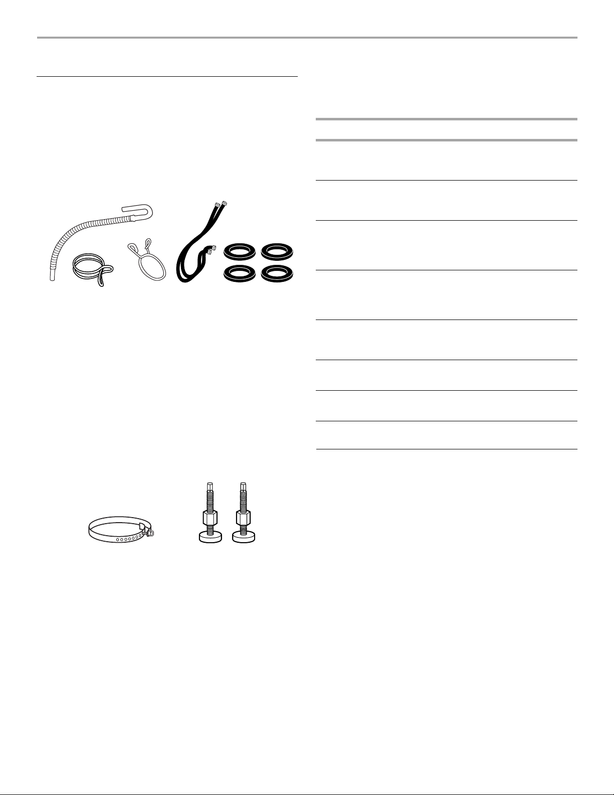
Parts supplied:
⁹⁄₁₆
in. (3.95 cm)
Alternate Parts
Your installation may require additional parts. For ordering
information, please refer to the toll free phone numbers on the
front page of your “Washer User Instructions.”
If You Have: You Will Need to Buy:
Laundry tub or
standpipe taller
than 96 in. (2.4 m)
1 in. (2.5 cm)
diameter
standpipe
Sump pump system (if not already
available)
2 in. (5 cm) diameter to 1 in. (2.5 cm)
diameter standpipe adapter, Part No.
3363920
12 34 5
1. Drain hose
2. Silver, double-wire hose clamp
(for the bottom of the drain hose)
3. Yellow, single-wire hose clamp
(for the top of the drain hose)
4. Water inlet hoses (2)
5. Flat water inlet hose washers (4)
Tools needed for securing the drain hose and
leveling the washer:
■
Adjustable or open end wrench
■
Level
■
Wood block
■
Ruler or measuring tape
Parts supplied:
12
1. Shipping strap with fastener
2. Front leveling feet with nuts (2)
⁹⁄₁₆
in. (14 mm)
Overhead sewer Standard 20 gal. (76 L) 39 in. (99 cm) tall
Floor drain Siphon break, Part Number 285320;
Water faucets
beyond reach of
fill hoses
Drain hose too
short
Drain hose that is
too long
Lint clogged drain Drain protector, Part No. 367031
drain tub or utility sink, sump pump and
connectors (available from local
plumbing suppliers)
additional drain hose, Part Number
3357090 and connector kit,
Part Number 285442
2 longer water fill hoses:
6 ft (1.8 m) Part Number 76314,
10 ft (3.0 m) Part Number 350008
Drain hose, Part No. 388423 and hose
kit, Part No. 285442
Hose kit, Part No. 285442
Location Requirements
Selecting the proper location for your washer improves
performance and minimizes noise and possible washer “walk.”
Your washer can be installed in a basement, laundry room,
closet, or recessed area. (See “Drain System.”)
IMPORTANT:
exposed to the weather.
Proper installation is your responsibility.
You will need:
■
A water heater set to deliver 120°F (49°C) water to the
washer.
■
A grounded electrical outlet located within 4 ft (1.2 m) of
where the power cord is attached to the back of the washer.
(See “Electrical Requirements.”)
■
Hot and cold water faucets located within 4 ft (1.2 m) of the
hot and cold water fill valves, and water pressure of 5-100 psi
(34.5-690 kPa). Washers with triple dispensers require
20-100 psi (138-690 kPa) for best performance.
■
A level floor with a maximum slope of 1 in. (2.5 cm) under
entire washer. Installing the washer on carpeting is not
recommended.
■
A sturdy floor to support the washer weight (washer, water
and load) of 315 lbs (143 kgs).
Do not install or store the washer where it will be
2
Do not store or operate your washer in temperatures at or below
32°F (0°C). Some water can remain in the washer and can cause
damage in low temperatures. See “Washer Care” in the
Washer User Instructions for winterizing information.
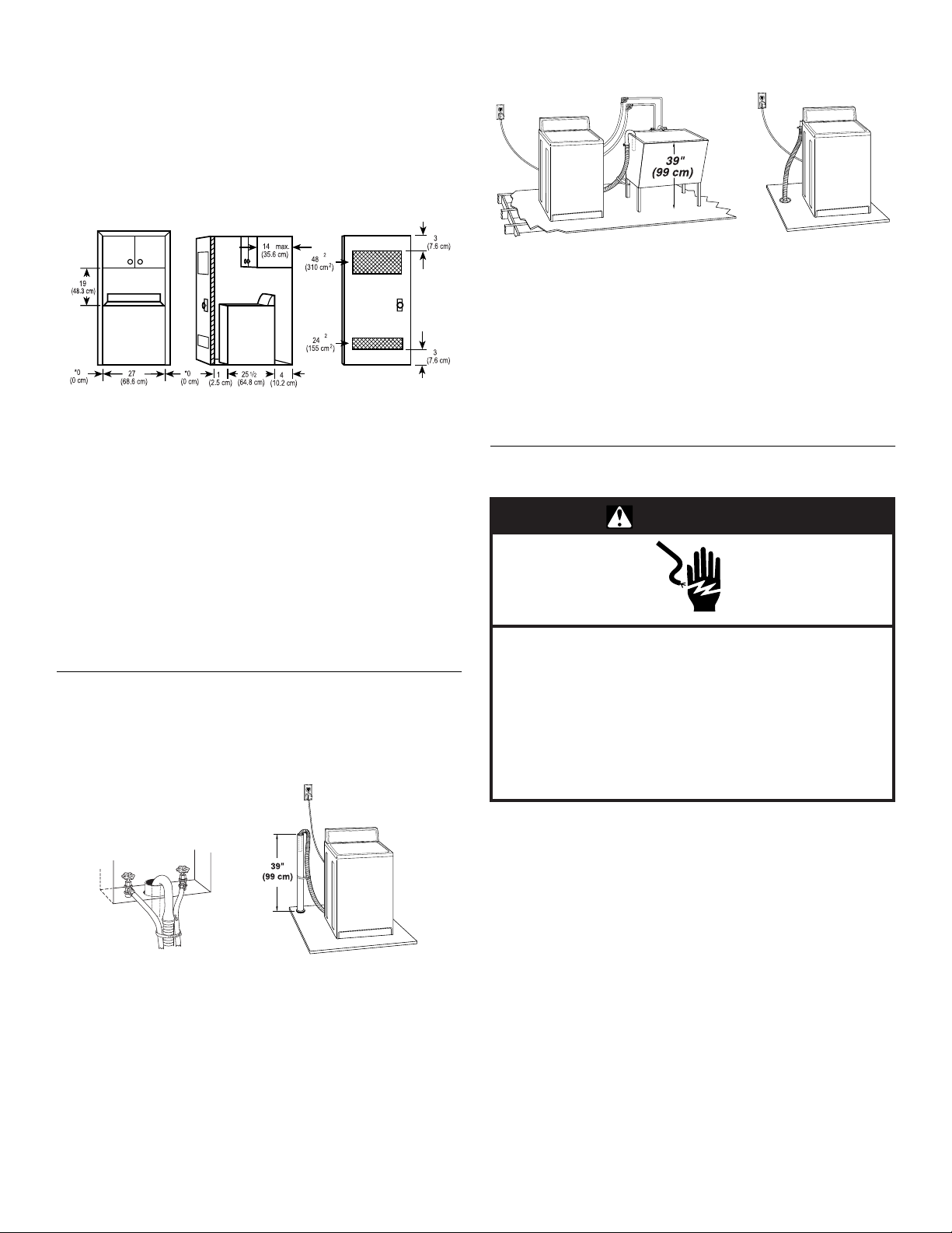
Recessed area or closet installation
The dimensions shown are for the recommended spacing
allowed, except the closet door ventilation openings. The
dimensions shown for the closet door ventilation openings are
the minimum required.
The top of the standpipe must be at least 39 in. (99 cm) high and
no higher than 96 in. (244 cm) from the bottom of the washer.
"
"
"
"
"
"
"
"
"
"
"
"
12 3
1. Front view
2. Side view
3. Closet door with vents
■
Additional spacing should be considered for ease of
installation and servicing.
■
Additional clearances may be required for wall, door and floor
moldings.
■
Additional spacing of 1 in. (2.5 cm) on all sides of the washer
is recommended to reduce noise transfer.
■
If a closet door is installed, the minimum air openings in the
top and bottom of the door are required. Louvered doors with
air openings in the top and bottom are acceptable.
■
Companion appliance spacing should also be considered.
Drain System
The washer can be installed using the standpipe drain system
(floor or wall), the laundry tub drain system, or the floor drain
system. Select the drain hose installation method you need. See
“Alternate Parts.”
12
Laundry tub drain system (view 1)
The laundry tub needs a minimum 20 gal. (76 L) capacity. The top
of the laundry tub must be at least 39 in. (99 cm) above the floor
and no higher than 96 in. (244 cm) from the bottom of the washer.
Floor drain system (view 2)
The floor drain system requires a siphon break that may be
purchased separately. See “Alternate Parts.”
The siphon break must be a minimum of 28 in. (71 cm) from the
bottom of the washer. Additional hoses might be needed.
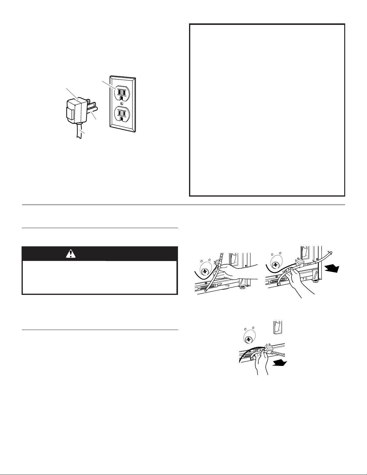
Electrical Requirements
WARNING
Electrical Shock Hazard
Plug into a grounded 3 prong outlet.
Do not remove ground prong
Do not use an adapter.
Do not use an extension cord.
Failure to follow these instructions can result in death,
fire, or electrical shock.
.
12
Standpipe drain system - wall or floor (view 1 & 2)
The standpipe drain requires a minimum diameter standpipe of
2 in. (5 cm). The minimum carry-away capacity can be no less
than 17 gal. (64 L) per minute. A 2 in. (5 cm) diameter to 1 in.
(2.5 cm) diameter standpipe adapter kit is available. See
“Alternate Parts.”
■
A 120-volt, 60-Hz., AC-only, 15- or 20-ampere, fused
electrical supply is required. Time-delay fuse or circuit
breaker is recommended. It is recommended that a separate
circuit serving only this appliance be provided.
■
This washer is equipped with a power supply cord having a 3
prong ground plug.
■
To minimize possible shock hazard, the cord must be
plugged into a mating, 3 prong, ground-type outlet, grounded
in accordance with local codes and ordinances. If a mating
outlet is not available, it is the personal responsibility and
obligation of the customer to have the properly grounded
outlet installed by a qualified electrician.
3
■
If codes permit and a separate ground wire is used, it is
recommended that a qualified electrician determine that the
ground path is adequate.
■
Do not ground to a gas pipe.
■
Check with a qualified electrician if you are not sure the
washer is properly grounded.
■
Do not have a fuse in the neutral or ground circuit.
2
1
GROUNDING INSTRUCTIONS
For a grounded, cord-connected washer:
This washer must be grounded. In the event of a malfunction
or breakdown, grounding will reduce the risk of electrical
shock by providing a path of least resistance for electric
current. This washer is equipped with a cord having an
equipment-grounding conductor and a grounding plug. The
plug must be plugged into an appropriate outlet that is
properly installed and grounded in accordance with all local
codes and ordinances.
3
4
1. 3 prong grounding plug
2. 3 prong grounding-type outlet
3. Ground prong
4. Power supply cord
INSTALLATION INSTRUCTIONS
Before You Start
WARNING
Excessive Weight Hazard
Use two or more people to move and install washer.
Failure to do so can result in back or other injury.
WARNING:
grounding conductor can result in a risk of electric shock.
Check with a qualified electrician or serviceman if you are in
doubt as to whether the appliance is properly grounded.
Do not modify the plug provided with the appliance – if it will
not fit the outlet, have a proper outlet installed by a qualified
electrician.
For a permanently connected washer:
This washer must be connected to a grounded metal,
permanent wiring system, or an equipment grounding
conductor must be run with the circuit conductors and
connected to the equipment-grounding terminal or lead on
the appliance.
pins on the end of the shipping strap when it is pulled out of
the washer. The electrical plug is attached to this shipping
strap.
Improper connection of the equipment-
■
To prevent floor damage, set the washer onto cardboard
before moving across floor.
■
Move the washer to within approximately 3 ft (90 cm) of the
final location.
Remove Shipping Strap
Removing the shipping strap is necessary for smooth operation.
If the shipping strap is not removed, the washer will make
excessive noise. The washer must be in the upright position
before removinig the shipping strap.
1.
Do not cut yellow strap. Pull yellow strap firmly, until
completely removed from washer. There will be two cotter
4
2.
Pull firmly to remove the end of the shipping strap that
remains pinned to the back of the washer. This will release
the rear self-leveling feet.
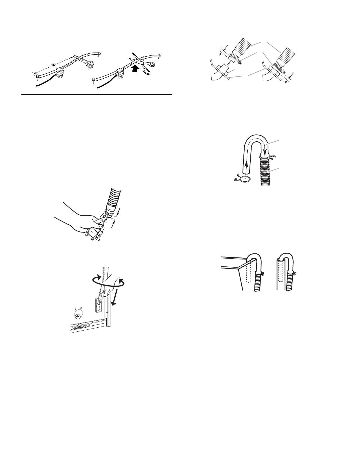
3.
)
)
1
2
Cut the shipping strap about 16 in. (40 cm) from plug end.
Look for the words “CUT HERE.” Discard end with the cotter
pins. Slide remainder of shipping strap from the power cord.
You will use the remainder of the shipping strap later to
secure the drain hose.
E
R
E
H
T
U
C
5.
Place clamp over area marked “CLAMP.” Release clamp.
1/4"
(6 mm)
1
2
1/4"
3
(6 mm
4
Connect Drain Hose
Proper connection of the drain hose will protect your floors from
damage due to water leakage. To prevent the drain hose from
coming off or leaking, it must be installed per the following
instructions.
IMPORTANT:
be followed exactly.
1.
Check the drain hose to see if it is the proper length.
2.
Wet the inside of the straight end of the drain hose with tap
water. DO NOT USE ANY OTHER LUBRICANT.
3.
Squeeze ears of silver, double-wire clamp with pliers to open.
Place clamp over the straight end of the drain hose
(6 mm) from the end.
4.
Open clamp. Twist hose back and forth while pushing down
onto drain connector at the bottom of the washer. Continue
until hose contacts the ribbed stop on the cabinet.
To ensure proper installation, this procedure must
¹⁄₄
in.
1/4"
(6 mm
1. Drain Hose
2. Clamp
3. Ribbed Stop
4. Cabinet
For standpipe or laundry tub drain systems:
1.
Open yellow, single-wire clamp with pliers and slide over
hooked end of drain hose to secure the rubber and
corrugated sections together.
1. Hooked end
2. Drain hose
2.
Put hooked end of drain hose into laundry tub or standpipe.
Rotate hook to eliminate kinks.
To prevent drain water from going back into the washer:
■
Do not straighten hooked end of drain hose. Do not force
excess drain hose into standpipe. Hose should be secure,
but loose enough to provide a gap of air.
■
Do not lay excess drain hose in bottom of laundry tub.
■
For floor drain installation, see kit number required under
“Alternate Parts.”
5
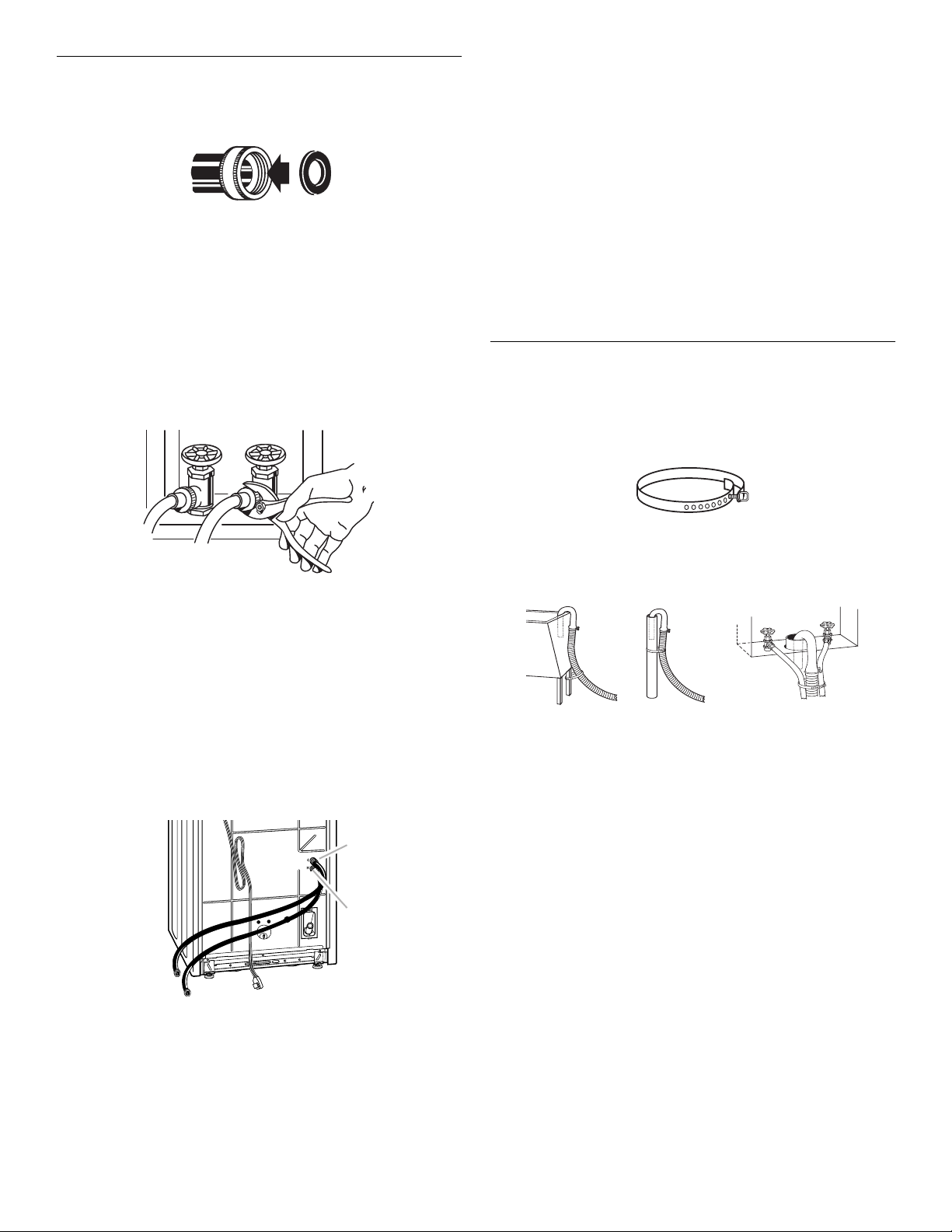
Connect the Inlet Hoses
12 3
1.
Insert new flat washers (supplied) into each end of the inlet
hoses. Firmly seat the washers in the couplings.
12
1. Coupling
2. Washer
Connect the inlet hoses to the water faucets
Make sure the washer basket is empty.
2.
Attach the hose with the red coupling to the hot water faucet.
Screw on coupling by hand until seated on the washer.
3.
Attach the hose with the blue coupling to the cold water
faucet. Screw on coupling by hand until seated on the washer.
4.
Using pliers, tighten the couplings with an additional twothirds turn.
7.
Attach the hose with the blue coupling to the COLD water
(top) inlet valve. Screw on coupling by hand until seated on
the washer. Using pliers, tighten the couplings with an
additional two-thirds turn.
NOTE:
Do not overtighten. Damage to the valves can result.
Check for leaks
8.
Turn on the water faucets and check for leaks. A small
amount of water might enter the washer. You will drain this
later.
NOTE:
Replace inlet hoses after 5 years of use to reduce the
risk of hose failure. Record hose installation or replacement
dates for future reference.
■
If you connect only one water hose, you must cap off the
remaining water inlet port.
■
Periodically inspect and replace hoses if bulges, kinks,
cuts, wear, or leaks are found.
Secure the Drain Hose
1.
Drape the power cord over the console.
2.
Remove any cardboard used to move washer.
3.
Locate the remaining portion of shipping strap (not the end
with the cotter pins) from step 3 of “Remove Shipping Strap.”
NOTE:
Do not overtighten. Damage to the valves can result.
Clear the water lines
5.
Run water through both faucets and inlet hoses, into a bucket
or laundry tub, to get rid of particles in the water lines that
might clog the inlet valve screens.
Connect the inlet hoses to the washer
6.
Attach the hose with the red coupling to the HOT (bottom)
inlet valve. Attaching the red coupling first makes it easier to
tighten connection with pliers. Screw on coupling by hand
until seated on the washer. Using pliers, tighten the couplings
with an additional two-thirds turn.
NOTE:
Do not overtighten. Damage to the valves can result.
1
2
Remaining portion of Shipping Strap
4.
Wrap the drain hose to the laundry tub leg or standpipe with
the tie strap. Push fastener into the nearest hole in the
shipping strap. (See illustration 1 or 2 below.)
If the washer faucets and the drain standpipe are recessed,
put the hooked end of the drain hose in the standpipe. Tightly
wrap the tie strap around the water inlet hoses and the drain
hose. (See illustration 3 above.)
1. Cold water inlet valve (blue)
2. Hot water inlet valve (red)
NOTE:
The inlet valve may be on the right or the left side of
the washer, depending on your model.
6
 Loading...